

Page 1

HF RADIO COMMUNICATIONS
3040 Automatic Whip Antenna
Installation Handbook
Page 2

No part of this handbook may be reproduced, transcribed,
translated into any language or transmitted in any form
whatsoever without the prior written consent of Codan
Limited.
© Copyright 2010 Codan Limited.
Codan part number 15-04166-EN Issue 1, June 2010.
Brand, product, and company names mentioned in this
document are trademarks or registered trademarks of their
respective holders.
The English version takes precedence over any translated
versions.
Page 3

Table of contents
Introduction
1Overview
General . . . . . . . . . . . . . . . . . . . . . . . . . . . . . . . . . . . . . . . . . . . . . . . . . . . . . 4
Care and safety instructions . . . . . . . . . . . . . . . . . . . . . . . . . . . . . . . . . . . . . 5
Connectors . . . . . . . . . . . . . . . . . . . . . . . . . . . . . . . . . . . . . . . . . . . . . . . . . . 6
2 Installing the antenna
Disclaimer. . . . . . . . . . . . . . . . . . . . . . . . . . . . . . . . . . . . . . . . . . . . . . . . . . 10
What you need to consider . . . . . . . . . . . . . . . . . . . . . . . . . . . . . . . . . . . . . 10
Installing a 3040 Automatic Whip Antenna . . . . . . . . . . . . . . . . . . . . . . . . 18
Installing an NVIS kit with a 3040 Automatic Whip Antenna. . . . . . . . . . 21
3 Specifications
General . . . . . . . . . . . . . . . . . . . . . . . . . . . . . . . . . . . . . . . . . . . . . . . . . 23
Mechanical . . . . . . . . . . . . . . . . . . . . . . . . . . . . . . . . . . . . . . . . . . . . . . 24
Environmental . . . . . . . . . . . . . . . . . . . . . . . . . . . . . . . . . . . . . . . . . . . . 25
4 Accessories
Appendix A—Compliance
Introduction. . . . . . . . . . . . . . . . . . . . . . . . . . . . . . . . . . . . . . . . . . . . . . . . . 30
European R&TTE Directive . . . . . . . . . . . . . . . . . . . . . . . . . . . . . . . . . . . . 30
EMC and safety notices . . . . . . . . . . . . . . . . . . . . . . . . . . . . . . . . . . . . . . . 31
FCC compliance . . . . . . . . . . . . . . . . . . . . . . . . . . . . . . . . . . . . . . . . . . . . . 33
Register of hazardous substances . . . . . . . . . . . . . . . . . . . . . . . . . . . . . . . . 34
Automatic Whip Antenna 3040 Installation Handbook i
Page 4

Table of contents
Appendix B—Definitions
Standards and icons . . . . . . . . . . . . . . . . . . . . . . . . . . . . . . . . . . . . . . . . . . . 37
Acronyms and abbreviations . . . . . . . . . . . . . . . . . . . . . . . . . . . . . . . . . . . . 38
Units. . . . . . . . . . . . . . . . . . . . . . . . . . . . . . . . . . . . . . . . . . . . . . . . . . . . . . . 39
Unit multipliers . . . . . . . . . . . . . . . . . . . . . . . . . . . . . . . . . . . . . . . . . . . . . . 40
About this issue . . . . . . . . . . . . . . . . . . . . . . . . . . . . . . . . . . . . . . . . . . . . . . 40
Index
List of figures
Figure 1: 3040 Automatic Whip Antenna. . . . . . . . . . . . . . . . . . . . . 4
Figure 2: Connectors on the antenna tuner . . . . . . . . . . . . . . . . . . . . 6
Figure 3: Front view of the antenna control connector. . . . . . . . . . . 7
Figure 4: Mounting footprint . . . . . . . . . . . . . . . . . . . . . . . . . . . . . 12
Figure 5: Rear-mount location on sedan vehicle . . . . . . . . . . . . . . 13
Figure 6: Rear-mount location on off-road vehicle . . . . . . . . . . . . 14
Figure 7: Front-mount location on off-road vehicle . . . . . . . . . . . . 14
Figure 8: 3040 antenna with NVIS kit . . . . . . . . . . . . . . . . . . . . . . 21
List of tables
Table 1: Pinouts for the antenna control connector. . . . . . . . . . . . . 7
Table 2: 3040 to NGT connections . . . . . . . . . . . . . . . . . . . . . . . . 19
Table 3: General specifications . . . . . . . . . . . . . . . . . . . . . . . . . . .23
Table 4: Mechanical specifications . . . . . . . . . . . . . . . . . . . . . . . . 24
Table 5: Environmental specifications . . . . . . . . . . . . . . . . . . . . . 25
Table 6: Accessories for the 3040 Automatic Whip
Antenna . . . . . . . . . . . . . . . . . . . . . . . . . . . . . . . . . . . . . . 27
Table 7: 有毒有害物质列表 (Register of hazardous
substances). . . . . . . . . . . . . . . . . . . . . . . . . . . . . . . . . . . . 34
ii Automatic Whip Antenna 3040 Installation Handbook
Page 5

Introduction
This handbook is for installers of the 3040 Automatic Whip
Antenna. It assumes that you have experience in installing
antennas.
This handbook contains the following sections:
Section 1 Overview—provides an overview of the
Section 2 Installing the antenna—provides guidance on
Section 3 Specifications—provides the common
Section 4 Accessories—lists the accessories available for
Appendix A Compliance—provides compliance information
Appendix B Definitions—explains the terms and
antenna, connectors, and general information
how to position, install, and earth the antenna
operational, environmental, and physical
specifications of the antenna
the antenna
and safety notices for your antenna
abbreviations used in this handbook
There is an index at the end of this handbook.
Automatic Whip Antenna 3040 Installation Handbook 1
Page 6

Introduction
This page has been left blank intentionally.
2 Automatic Whip Antenna 3040 Installation Handbook
Page 7

1 Overview
This section contains the following topics:
General (4)
Care and safety instructions (5)
Connectors (6)
Automatic Whip Antenna 3040 Installation Handbook 3
Page 8

Overview
base plate
antenna tuner
spring
riser
whip
(fibreglass or
stainless steel)
240 mm
(9.4 in)
865 mm
(34.0 in)
1575 mm
(62.0 in)
115 mm
(4.5 in)
2795 mm
(3 yd)
General
The 3040 Automatic Whip Antenna is designed to provide
continuous tuning for vehicle-mounted transceivers that scan
multiple frequencies. It is designed to withstand extreme
environmental and physical conditions. When tuning, the
antenna seeks the optimum tuning point, ensuring that the best
communications possible are achieved.
The 3040 Automatic Whip Antenna comprises:
• a 1.6 m (62 in) fibreglass or stainless steel whip
• an 865 mm (34.0 in) riser
•a spring
• an antenna tuner with connectors, base plate and earth
wire
Figure 1: 3040 Automatic Whip Antenna
4 Automatic Whip Antenna 3040 Installation Handbook
Page 9

Care and safety instructions
You should unscrew the whip and riser from the antenna base
when the antenna is not in use.
When travelling in scrub or undergrowth, avoid overhanging
branches.
Overview
Automatic Whip Antenna 3040 Installation Handbook 5
Page 10

Overview
RF
Antenna
control
Connectors
There are two connectors at the base of the antenna as shown
in Figure 2.
Figure 2: Connectors on the antenna tuner
6 Automatic Whip Antenna 3040 Installation Handbook
Page 11

Overview
A
B
C
D
E
F
Figure 3: Front view of the antenna control connector
Table 1: Pinouts for the antenna control connector
Pin no. Description
A+12VDC
BEarth
CTune
D Scan
E Tune status indicator
F Not used
Automatic Whip Antenna 3040 Installation Handbook 7
Page 12

Overview
This page has been left blank intentionally.
8 Automatic Whip Antenna 3040 Installation Handbook
Page 13

2 Installing the antenna
This section contains the following topics:
Disclaimer (10)
What you need to consider (10)
Installing a 3040 Automatic Whip Antenna (18)
Installing an NVIS kit with a 3040 Automatic Whip
Antenna (21)
Automatic Whip Antenna 3040 Installation Handbook 9
Page 14

Installing the antenna
Disclaimer
The antenna should be installed by a suitably-
WARNING
WARNING
qualified technician, to the relevant standards
and approvals.
While the following instructions are intended to
assist with installation, it is the purchaser’s
responsibility to ensure that the antenna is
installed with due regard to pedestrian and
vehicle-occupant safety, particularly in the
event of a vehicle accident. Codan accepts no
responsibility or liability in the event of injury
to pedestrians or vehicle occupants or any other
damage due to insecure or otherwise unsafe or
inappropriate installation of the antenna.
What you need to consider
The antenna is a critical element in an HF communications
system. Correct installation of the antenna provides efficient
operation over the frequency range of the transceiver. A good
installation ensures the antenna provides optimum output
power during transmission and clear reception of weak
signals.
When installing the antenna you must consider:
• the location and mounting of the antenna
• how to provide a good earth plane for the antenna
• the routing of the coaxial and control cable
10 Automatic Whip Antenna 3040 Installation Handbook
Page 15

Installing the antenna
Location
To obtain optimal radiation efficiency from your antenna, and
optimal reception at your antenna, it must be mounted in a
location that:
• is clear of surrounding body work
• supports a good earth plane
• supports the RF earthing required for correct tuning and
loading
• allows for best radiation (open and clear of all metal
obstructions)
When mounted, the antenna:
• must not obscure the driver’s vision
• must not obscure number plates or vehicle lights
• should not interfere with engine or car openings
• must clear electric power lines, overhanging trees,
bridges etc
• must not breach vehicle-licensing regulations
A mounted antenna must have:
• a strong anchorage for the base of the antenna
• a sound electrical connection to the vehicle chassis
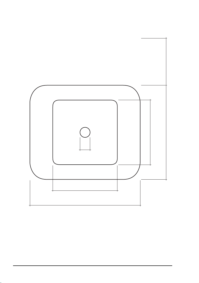
The mounting footprint in Figure 4 on page 12 shows the
required space for the base of the antenna tuner.
Automatic Whip Antenna 3040 Installation Handbook 11
Page 16
Installing the antenna
15 mm
96 mm
164 mm
96 mm
140 mm
NOTE
Allow 70 mm over the
cable connections and for
minimum bending radius
Connectors
70 mm
Figure 4: Mounting footprint
12 Automatic Whip Antenna 3040 Installation Handbook
Page 17

Installing the antenna
Possible mounting locations that provide good electrical
performance of the 3040 Automatic Whip Antenna are shown
in the following photographs.
Figure 5: Rear-mount location on sedan vehicle
Automatic Whip Antenna 3040 Installation Handbook 13
Page 18

Installing the antenna
fibreglass canopy
left-hand drive
position
right-hand drive
position
Figure 6: Rear-mount location on off-road vehicle
Figure 7: Front-mount location on off-road vehicle
14 Automatic Whip Antenna 3040 Installation Handbook
Page 19

Installing the antenna
If the antenna is front-mounted, it should be
CAUTION
mounted on the side opposite to the driving
position.
Mounting bracket
The antenna must be mounted on a sturdy metal plate (at least
8 mm (0.3 in) thick). The mounting bracket and fixing should
be able to withstand any vibrations induced from the vehicle
travelling over an off-road surface. A strong metal plate that is
large enough to support the antenna will also provide efficient
earthing. The plate must have a 15 mm (0.6 in) hole to accept
the mounting screw.
NOTE
You should consider any overall height
restrictions that are relevant to your vehicle.
The bracket should be located so that any flexing of the
antenna assembly does not damage the panels of the vehicle.
The installed antenna should enable easy access to the
connectors.
Automatic Whip Antenna 3040 Installation Handbook 15
Page 20

Installing the antenna
Earthing
Most mobile antennas are considerably shorter than a quarter
wavelength at HF, and can exhibit an extremely low radiation
resistance. Consequently, their efficiency is reduced compared
with the quarter-wave radiator that they represent. This can be
improved by good installation practices, and most importantly,
by the provision of a low-impedance earth return for the
antenna.
Due to the relatively poor earth plane surrounding a mobile
HF antenna, best use should be made of what is available. A
reduction in any losses can increase antenna current and
radiation. This can often be achieved by providing a good
earth connection from the base of the antenna to nearby
bodywork. An earth wire is provided for this. Connections to
the vehicle chassis are not as effective because many 4WD
vehicles have insulating mountings from body to chassis.
A strong metal plate that is large enough to support the
antenna will provide efficient earthing. The plate should be
welded to the chassis or some other part of the vehicle’s frame.
The mounting bracket and plate must be free of rust and paint
to allow metal-to-metal contact between the base of the
antenna and the mounting bracket. This electrical bond is the
basis for effective RF earthing. RF currents flow on the
conductor surface, therefore good RF earthing requires
conductors with large surface areas.
NOTE
Conductive grease should be used on the
touching surfaces to help prevent corrosion.
The RF earth differs from the DC earth required by the battery
and the vehicle’s electrics. For more information on power
supply factors and earthing the transceiver, see the
documentation provided with the transceiver.
16 Automatic Whip Antenna 3040 Installation Handbook
Page 21

Installing the antenna
Cabling
The coaxial cable between the antenna and the transceiver
should be installed as far as possible from other vehicle
wiring, especially high-tension ignition wiring or the engine
management computer.
The cabling must be in a position that:
• is away from the driver’s feet
• is secured and concealed as much as possible
• is secured behind protective metalwork (only if the
cables run under the vehicle)
Keep cables in the engine compartment away from:
• heat, for example, exhaust, air-conditioning systems, and
water pipes
• oils and corrosive liquids, for example, engine oil,
battery fluid, and brake fluid
Protect all the cables from sharp edges and mechanical
abrasions. Cables that pass through body panels or internal
bulkheads must be protected by rubber grommets. Holes in the
bulkhead need only be large enough to allow the end of the
cable with the smaller connector to pass through. Removing a
connector should be a last resort.
CAUTION
Removal of factory-fitted connectors may cause
cable or connector faults.
Crimp-style coaxial connectors are not suitable
CAUTION
for vehicle installations because they are not
weatherproof.
NOTE
Automatic Whip Antenna 3040 Installation Handbook 17
Any cabling under carpet or floor mats should
be clear of foot traffic.
Page 22

Installing the antenna
Installing a 3040 Automatic Whip Antenna
To install the antenna on a vehicle:
1 Attach the mounting bracket to the vehicle in a manner
that complies with the relevant safety standards and
approvals.
1 Clean the mounting surface of all dirt, rust, and paint.
NOTE
Codan recommends that conductive grease
is applied to the mounting surface.
1 Remove the M14 nut and all washers from the M14
mounting stud at the base of the antenna.
1 Insert the mounting stud into the hole on the mounting
bracket, then locate the flat washer, spring washer, and
nut onto the mounting stud.
1 Tighten the nut until the spring washer is compressed.
1 Connect an earth wire to a convenient bolt on the
bodywork.
NOTE
Ensure a good electrical connection is
made.
1 If you are connecting the antenna to:
• an NGT Transceiver see the cable connections
provided in Table 2
• a 2110 Manpack Transceiver see the Fitting
Instructions provided with the mounting cradle and or
equipment
18 Automatic Whip Antenna 3040 Installation Handbook
Page 23

Table 2: 3040 to NGT connections
Installing the antenna
Codan part
number
08-05627-xxx Multicore,
08-01503-xxx 50 coaxial RG58,
Cable type From connector on
6m (19ft)
6m (19ft)
NOTE
WARNING
1 Protect any cables passing through metal panels with
rubber grommets.
1 Tape the connectors on the antenna, and approximately
25 mm (1 in) of each cable, with two layers of selfamalgamating PIB tape (Rotunda 2501) or EPR tape (3M
Scotch™ 23).
To lead from
antenna tuner...
6-way antenna control
RF
These cables are available in a number of
lengths (see page 27, Accessories).
Do not cut the control or coaxial cable. If
the cables are too long, coil the excess
neatly and secure it out of the way with
cable ties.
Do not bunch the control and coaxial
cables together.
RF unit...
1 Cover the self-amalgamating tape with two layers of
high-quality electrical tape (3M Scotch™ 33+, or
similar) to minimise aging of the self-amalgamating tape.
1 Screw the fibreglass or stainless steel whip to the riser,
then screw the riser to the spring.
1 Screw the spring onto the antenna stud at the top of the
housing of the antenna tuner.
Automatic Whip Antenna 3040 Installation Handbook 19
Page 24

Installing the antenna
Do not exert greater than 25 Nm (18 lb-ft)
on the stud. Tighten the whip using a
WARNING
spanner with one hand positioned as close
as possible to the antenna to minimise any
mechanical advantage.
1 Test the installed antenna (with connected transceiver) as
described in the documentation provided with your
transceiver.
If the length of the antenna is changed, for
example, removal of the riser or addition of
the NVIS kit, Codan recommends that you
NOTE
NOTE
manually tune the antenna (press 1) on
each frequency you want to use. This sets
the optimum tuning point in the memory of
the tuner.
Troubleshooting for an antenna and how to
install a transceiver are provided in the
Reference or Operator Manual.
20 Automatic Whip Antenna 3040 Installation Handbook
Page 25

Installing the antenna
Installing an NVIS kit with a 3040 Automatic Whip Antenna
An NVIS kit (Codan part number 78-14010) is available for
attaching to a 3040 antenna. For information on installing this
kit with the antenna see the instructions provided with the kit.
The NVIS kit is designed to improve the performance of short
to medium-range HF communications for the 3040 antenna by
increasing the high-angle radiation characteristics. Typically,
these communication distances are 20 to 500 km (12 to
310 mi). The operating frequency range when using the NVIS
kit is 2 to 12 MHz.
The vertical radiation pattern from a short vertical whip
antenna is very poor. As such, HF communications over short
distances may be difficult or non-existent from such an
antenna. The NVIS kit lengthens the whip section of the 3040
antenna. The NVIS whip is longer and positioned horizontally
to improve the vertical radiation efficiency.
Figure 8: 3040 antenna with NVIS kit
direction of
propagation
of skywave
NVIS extension
section
angle
adaptor
1 m
riser
Automatic Whip Antenna 3040 Installation Handbook 21
top stainless steel
whip section
tie-down
cord
roof gutter
clamps
Page 26

Installing the antenna
NOTE
When the NVIS kit is added or removed,
Codan recommends that you manually tune
the antenna (press 1) on each frequency
you want to use. This sets the optimum
tuning point in the memory of the tuner.
22 Automatic Whip Antenna 3040 Installation Handbook
Page 27

3 Specifications
General
Table 3: General specifications
Item Specification
Frequency range 2.5 to 30 MHz (2.4 m whip)
2 to 12 MHz (4 m NVIS)
DC operating range 10 to 15.5 V DC
12 V DC nominal
Power rating 125 W PEP, voice and data
Power
consumption
Input impedance 50
VSWR
Tuning speed 1 s average for a new frequency
Memory channels Unlimited
Connectors Antenna control: 6-way
Cables Antenna control: Pre-assembled multicore cable available
0.4 A, typical
< 0.8 A, maximum
≤ 1.5:1, typical
< 150 ms from memory
RF: UHF socket
in a a number of lengths (see page 27,
Accessories)
Coaxial: RG58 cable available in a number of
lengths (see page 27, Accessories)
Automatic Whip Antenna 3040 Installation Handbook 23
Page 28

Specifications
Mechanical
Table 4: Mechanical specifications
Item Specification
Size Base: 145 mm W × 165 mm D × 240 mm H
(5.7inW × 6.5inD × 9.4inH)
Spring: 115 mm
(4.5 in)
Fibreglass riser: 0.9 m
(34.0 in)
Fibreglass whip: 1.6 m
(62.0 in)
Stainless steel
whip:
1.6 m
(62.0 in)
NVIS extension: 1.6 m
(62.2 in)
Weight Base: 3.0 kg
(6.6 lb)
Spring: 0.8 kg
(1.7 lb)
Fibreglass riser: 0.3 kg
(0.7 lb)
Fibreglass whip: 0.3 kg
(0.7 lb)
Stainless steel
whip:
Rigid/bent
adaptor:
0.2 kg
(0.5 lb)
0.2 kg
(0.5 lb)
NVIS extension: 0.4 kg
(1.0 lb)
24 Automatic Whip Antenna 3040 Installation Handbook
Page 29

Table 4: Mechanical specifications (cont.)
Item Specification
Mounting M14 stud
40 mm long
(1.6 in long)
Colour Black
Environmental
Table 5: Environmental specifications
Item Specification
Temperature range –40 to 70°C
Relative humidity 95%
Specifications
MIL-STD-810F
compliance
Method 512.4: Immersion
Method 510.4: Dust
Method 514.5: Vibration
MIL-STD-461
Meets EMC requirements for susceptibilities and emissions
compliance
Automatic Whip Antenna 3040 Installation Handbook 25
Page 30

Specifications
This page has been left blank intentionally.
26 Automatic Whip Antenna 3040 Installation Handbook
Page 31

4 Accessories
Table 6: Accessories for the 3040 Automatic Whip
Antenna
Codan part
number
08-01503-002 Cable, coaxial, waterproof (2 m)
08-01503-006 Cable, coaxial, waterproof (6 m)
08-01503-008 Cable, coaxial, waterproof (8 m)
08-01503-030 Cable, coaxial, waterproof (30 m)
08-05627-006 Cable, control, NGT–9350 (6 m)
08-05627-008 Cable, control, NGT–9350 (8 m)
08-05627-030 Cable, control, NGT–9350 (30 m)
08-07008-001 Spring
78-14010 NVIS kit
78-18058 Riser, fibreglass
78-23085 Whip, fibreglass
78-23086 Whip, stainless steel
Description
Automatic Whip Antenna 3040 Installation Handbook 27
Page 32

Accessories
This page has been left blank intentionally.
28 Automatic Whip Antenna 3040 Installation Handbook
Page 33

Appendix A Compliance
This section contains the following topics:
Introduction (30)
European R&TTE Directive (30)
EMC and safety notices (31)
FCC compliance (33)
Register of hazardous substances (34)
Automatic Whip Antenna 3040 Installation Handbook 29
Page 34

Compliance
0191
0191
Introduction
This section describes how to ensure the 3040 Automatic
Whip Antenna complies with the European EMC Directive
89/336/EEC and the European LV Directive 73/23/EEC as
called up in the European R&TTE Directive 1999/5/EC.
This section also contains the requirements for FCC
compliance.
European R&TTE Directive
The 3040 Automatic Whip Antenna has been tested and
complies with the following standards and requirements
(articles of the R&TTE Directive):
• Article 3.1b: ETSI EN301489-1 V1.4.1
• Article 3.1b: ETSI EN301489-15 V1.2.1
• Article 3.1a: EN60950-1
Product marking and labelling
Any equipment supplied by Codan that satisfies these
requirements is identified by the , or
markings on the model label of the product.
Declaration of Conformity
The CE Declaration of Conformity for the product is listed on
page 40, Associated documents. This document can be made
available upon request to Codan or a Codan-authorised
supplier.
30 Automatic Whip Antenna 3040 Installation Handbook
Page 35

EMC and safety notices
Non-ionising radiation safety
To ensure optimal transceiver performance and to avoid
exposure to excessive electromagnetic fields, the antenna
system must be installed according to the instructions
provided.
High voltages exist on the antenna during
WARNING
WARNING
WARNING
transmission and tuning. Do not touch the
antenna during these activities. RF burns may
result.
Install the earthing system or counterpoise as
directed to prevent RF burns from any metal
part of the transceiver.
You should not transmit from your transceiver
or tune the antenna unless people are beyond the
safe working distance of 1.5 m (5 ft) of any part
of a 3040 Automatic Whip Antenna.
Compliance
Safe working distance is based on continuous exposure to
CW-type transmissions, as set out in the ICNIRP Exposure
Guidelines (1998) for occupational exposure. Safe working
distance can be reduced with normal voice communication.
EMC
To ensure compliance with the EMC Directive is maintained,
you must:
1 Use the standard shielded cables supplied from Codan
(where applicable).
Automatic Whip Antenna 3040 Installation Handbook 31
Page 36

Compliance
Electrical safety
To ensure compliance with the European LV Directive is
maintained, you must install the 3040 Automatic Whip
Antenna in accordance with the instructions in this handbook,
and operate the 3040 Automatic Whip Antenna in accordance
with the instructions in the relevant documentation provided
with your transceiver.
32 Automatic Whip Antenna 3040 Installation Handbook
Page 37

FCC compliance
FCC Part 15 compliance
Any modifications made to the 3040 Automatic Whip
Antenna that are not approved by the party responsible for
compliance may void your equipment’s compliance under
Part 15 of the FCC rules.
The 3040 Automatic Whip Antenna has been tested and found
to comply with the limits for a Class B device, pursuant to
Part 15 of the FCC rules. These limits are designed to provide
reasonable protection against harmful interference in a
residential installation. This equipment generates, uses and
can radiate radio frequency energy and, if not installed and
used in accordance with the instructions, may cause harmful
interference to radio communications. However, there is no
guarantee that interference will not occur in a particular
installation. If this equipment does cause harmful interference
to radio or television reception, which can be determined by
switching the equipment off and on, the user is encouraged to
try to correct the interference by one or more of the following
measures:
Compliance
• reorient or relocate the receiving antenna
• increase the separation between the equipment and
receiver
• connect the equipment into an outlet on a circuit different
from that to which the receiver is connected
• consult the dealer or an experienced radio/TV technician
for help
Automatic Whip Antenna 3040 Installation Handbook 33
Page 38

Compliance
Register of hazardous substances
Ta bl e 7 : 有毒有害物质列表 (Register of hazardous
substances)
零件项目
(Component Name)
3040 天线
(3040 Antenna)
3040 主体结构
(3040 Main Assembly)
玻璃纤维鞭状天线
(Fibreglass Whip)
不锈钢鞭状天线
(Stainless Steel Whip)
弹簧
(Spring)
控制电缆
(Control Cable)
同轴电缆
(Coaxial Cable)
天线安装手册
(Antenna Installation Handbook)
有毒有害物质或元素
(Hazardous Substances or Elements)
铅
汞
镉
六价鉻
多溴联苯
多溴二苯醚
XOOOOO
XOOOOO
XOOOOO
OOOOOO
XOOOOO
XOOOOO
OOOOOO
34 Automatic Whip Antenna 3040 Installation Handbook
Page 39

Compliance
表示该有毒有害物质在该部件的所有均质材料中的含量 , 均在 SJ/T
O
11363-2006 标准所规定的限量要求以下 .
Indicates that this toxic or hazardous substance, contained in all of the
homogeneous materials for this part, is below the limit requirement in SJ/
T 11363-2006.
表示该有毒有害物质在该部件的至少一种均质材料中的含量 , 超出
X
SJ/T 11363-2006 标准所规定的限量要求 .
Indicates that this toxic or hazardous substance, contained in at least one of
the homogeneous materials used for this part, is above the limit requirement
in SJ/T 11363-2006.
怎么阅读制造日期 - 方法如下 :
How to read the date of manufacture:
产品序列号中的第一个数字或字母表示该产品在 2000 年或以后的制造年份
. 举例来说 ( 数字 0-9) 0=2000, 1=2001... 之后接着以字母代表制造年份
A=2010, B=2011...
The first character of the serial number provides the year of manufacture starting
from the year 2000, that is, 0=2000, 1=2001...A=2010, B=2011...
产品序列号中的第二个数字或字母表示该产品的制造月份 . 举例来说 ( 数字
1-9) 1= 一月份 , 2= 二月份 ... 之后接着以字母 A,B,C 代表剩下的制造月
份 A= 十月份 , B= 十一月份 ,C= 十二月份 .
The second character of the serial number provides the month of manufacture, that
is, 1 to 9, A to C; A=10
th
month, B=11thmonth and C=12th month.
Automatic Whip Antenna 3040 Installation Handbook 35
Page 40

Compliance
This page has been left blank intentionally.
36 Automatic Whip Antenna 3040 Installation Handbook
Page 41

Appendix B Definitions
Standards and icons
The following standards and icons are used in this handbook:
This typeface Means...
Italic a cross-reference or text requiring emphasis
This icon Means...
a step within a task
NOTE
CAUTION
WARNING
the text provided next to this icon may be
of interest to you
proceed with caution as your actions may
lead to loss of data, privacy or signal
quality
your actions may cause harm to yourself or
the equipment
Automatic Whip Antenna 3040 Installation Handbook 37
Page 42

Definitions
Acronyms and abbreviations
This term... Means...
4WD four-wheel drive
CW continuous wave
DC direct current
EMC electromagnetic compatibility
EPR ethylene propylene rubber
ETSI European Telecommunications Standards
Institute
FCC Federal Communications Commission
HF high frequency
ICNIRP International Commission on Non-Ionizing
Radiation Protection
LV low voltage
NVIS near vertical-incident skywave
PIB poly isobutylene
R&TTE radio and telecommunications terminal
equipment
RF radio frequency
VSWR voltage standing wave ratio
38 Automatic Whip Antenna 3040 Installation Handbook
Page 43

Units
Definitions
NOTE
Measurement Unit Abbreviation
Current ampere A
Frequency hertz Hz
Impedance ohm
Length metre
Power watt W
Temperature degrees Celsius
Time second s
Torque newton-metre
Vo l t a g e v o l t V
Weight gram
Imperial dimensions are in United States
Customary Units.
m
(inch/feet)
(Fahrenheit)
(pound-foot)
(pound)
(in/ft)
°C
(°F)
Nm
(lb-ft)
g
(lb)
Automatic Whip Antenna 3040 Installation Handbook 39
Page 44

Definitions
Unit multipliers
NOTE
Unit Name Multiplier
M mega 1000 000
k kilo 1000
m milli 0.001
About this issue
This is the first issue of the Automatic Whip Antenna 3040
Installation Handbook.
Units are expressed in accordance with ISO
1000:1992 ‘SI units and recommendations for
the use of their multiples and of certain other
units’.
Associated documents
This handbook is one of a series of documents associated with
the 3040 Automatic Whip Antenna. The other documents are:
• Declaration of Conformity for the 3040 Automatic Whip
Antenna (Codan part number 19-40366)
40 Automatic Whip Antenna 3040 Installation Handbook
Page 45

Index
Numerics
3040 to transceiver connections 18
A
accessories 27
antenna
cabling 17
changing length 20
components 4
dimensions 4, 24
earthing 16
installing 18
location 11
mounting bracket 15
C
cabling 17
care and safety instructions 5
changing antenna length 20
compliance
EMC and safety notices 31
electrical safety 32
EMC 31
radiation safety 31
FCC 33
R&TTE Directive 30
declaration of conformity 30
product marking and labelling 30
connectors 6
antenna control 7
correct installation 10
F
FCC compliance 33
footprint 12
G
general specifications 23
H
hazardous substances 34
height restrictions 15
L
location 11
M
mechanical specifications 24
mounting
bracket 15
footprint 12
front
off-road vehicle 14
rear
off-road vehicle 14
sedan vehicle 13
N
NVIS kit 21
O
E
earthing 16
EMC and safety notices
compliance
electrical safety 32
EMC 31
radiation safety 31
environmental specifications 25
Automatic Whip Antenna 3040 Installation Handbook Index-1
optimal tuning point 20
overview 3
P
pinouts 7
Page 46

Index
R
R&TTE Directive
compliance 30
declaration of conformity 30
product marking and labelling 30
S
safety
electrical 32
radiation 31
specifications 23
environmental 25
general 23
mechanical 24
Index-2 Automatic Whip Antenna 3040 Installation Handbook
Page 47

www.codan.com.au
Asia Pacific (Head Office)
Codan Limited
81 Graves Street
Newton SA 5074
AUSTRALIA
T: +61 8 8305 0311
F: +61 8 8305 0411
asiasales@codan.com.au
Europe, Middle-East & Africa
Codan (UK) Ltd
Unit C4, Endeavour Place
Coxbridge Business Park
Farnham Surrey GU10 5EH
UNITED KINGDOM
T: +44 1252 717 272
F: +44 1252 717 337
uksales@codan.com.au
Americas
Codan US, Inc.
1 Fishers Road
Pittsford NY 14534
USA
T: +1 585 419 9970
F: +1 585 419 9971
hfsales@codanusinc.com
 Loading...