

Coda S5 User Manual

TECHNOLOGIES INC.
Amplifier S5
OPERATION MANUAL
SAFETY PRECAUTIONS
INTRODUCTION
INSTALLATION CONNECTIONS
DETAILED INSTALLATION
DESIGN PHILOSOPHY
TECHNICAL DATA
CARE and HANDLING
WARRANTY
WARRANTY REGISTRATION
1
2
3
4
9
12
13
14
15
ADDRESS
16
SAFETY PRECAUTIONS
CAUTION
CAUTION
WARNING
WARNING
CAUTION: TO PREVENT ELECTRIC SHOCK,
DO NOT REMOVE COVER. NO USER
SERVICEABLE PARTS INSIDE, REFER
SERVICING TO QUALIFIED SERVICE
PERSONNEL.
THIS SYMBOL IS TO ALERT YOU OF THE
PRESENCE OF UNINSULATED DANGEROUS VOLTAGE WITHIN THE UNIT'S
ENCLOSURE THAT MAY BE OF SUFFICIENT MAGNITUDE TO CONSTITUTE A
RISK OF ELECTRIC SHOCK.
!
1
WARNING:
CAUTION -
THIS SYMBOL IS INTENDED TO ALERT
YOU OF THE PRESENCE OF IMPORTANT
OPERATING AND MAINTENANCE
!
TO PREVENT FIRE OR SHOCK HAZARD, DO NOT
EXPOSE THIS UNIT TO RAIN OR MOISTURE. TO
AVOID ELECTRICAL SHOCK, DO NOT OPEN THE
UNIT. REFER SERVICING TO QUALIFIED PERSONNEL.
Never install or remove the power cord from the chassis
unless it has been disconnected from the AC power source
first.
Never pull on the power cord when removing it from an AC
-
power source. Grasp it by the plug.
Do not leave the power cord connected to an AC power
-
source unless it is connected to the unit.
-
It is recommend that during extended periods of nonuse
that the units power cord be unpluged from its AC power
source.
Route the AC power cord so that it will not be damaged or
-
walked on.
INSTRUCTIONS IN THE LITERATURE
ACCOMPANYING THE UNIT.

INTRODUCTION
This amplifier is a precision device, designed in an effort to provide the listener with
unmatched sound quality, design, and construction. In order to operate your amplifier
properly and to realize all of the capabilites of the A mplifier S5 we recommend that
you read this entire manual carefully.
2
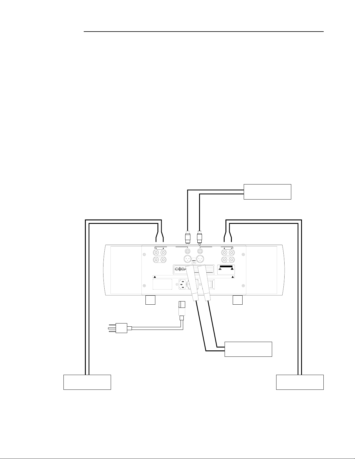
INSTALLATION CONNECTIONS
3
The first section of the installation instructions for the AMPLIFIER S5 is a diagram of the
default ( stereo ) configuration required to bring this amplifier into an operating mode.
These brief steps will allow you to begin operating your system. Make sure during
installation that the main AC power switch on the back of the AMPLIFIER
S5 is turned off.
While the diagram may be self explanatory, we strongly recommend that you read the
detailed instructions following this introductory section.
PREAMPLIFIER
LEFT SPEAKER
OUTPUT
FOR CONTINUED PROTECTION
AGAINST SHOCK OR FIRE:
1. REPLACE FUSE WITH SAME
TYPE AND RATING
2. DO NOT EXPOSE THIS UNIT
TO RAIN OR MOISTURE
AC LINE FUSE CHART
!
VOLTAGE FUSE TYPE
100V 10 AMP SLOW BLOW 5 x 20mm
120V 10 AMP SLOW BLOW 5 x 20mm
220V 5 AMP SLOW BLOW 5 x 20mm
240V 5 AMP SLOW BLOW 5 x 20mm
LEFT CHANNEL
INPUTS
UNBALANCED
BALANCED
TECHNOLOGIES INC.
AC LINE INPUT
~
SEE SERIAL TAG FOR POWER
REQUIREMENTS, REMOVE POWER
CORD BEFORE CHANGING
FUSE OR LINE VOLTAGE
MODE
STEREO
BRIDGED
MODEL
SERIAL NUMBER
VOLTAGE REQUIREMENT
POWER REQUIREMENT
FUSE AND VOLTAGE SELECTOR
12
0
FUSE VALUE -SEE FUSE CHART
VOLTAGE SELECTIONSEE OPERATION MANUAL
MANUFACTURED IN THE USA
INPUTS
UNBALANCED
BALANCED
VA
MAIN POWER
OFF ON
RIGHT CHANNEL
HZ
OUTPUT
CAUTION
CAUTION
ARNING
WWARNING
TO PREVENT ELECTRIC SHOCK, DO NOT
REMOVE COVER. NO USER SERVICEABLE
PARTS INSIDE. REFER SERVICING TO
QUALIFIED SERVICE PERSONNEL.
NOTE
DO NOT ALLOW AMPLIFIER OUTPUTS
TO COMMON BETWEEN CHANNELS,
OR CONTACT CHASSIS OR INPUT
GROUNDS, OR TO BE CONNECTED
TO ANY ACTIVE CURRENT SOURCE.
!
!
PREAMPLIFIER
RIGHT SPEAKER
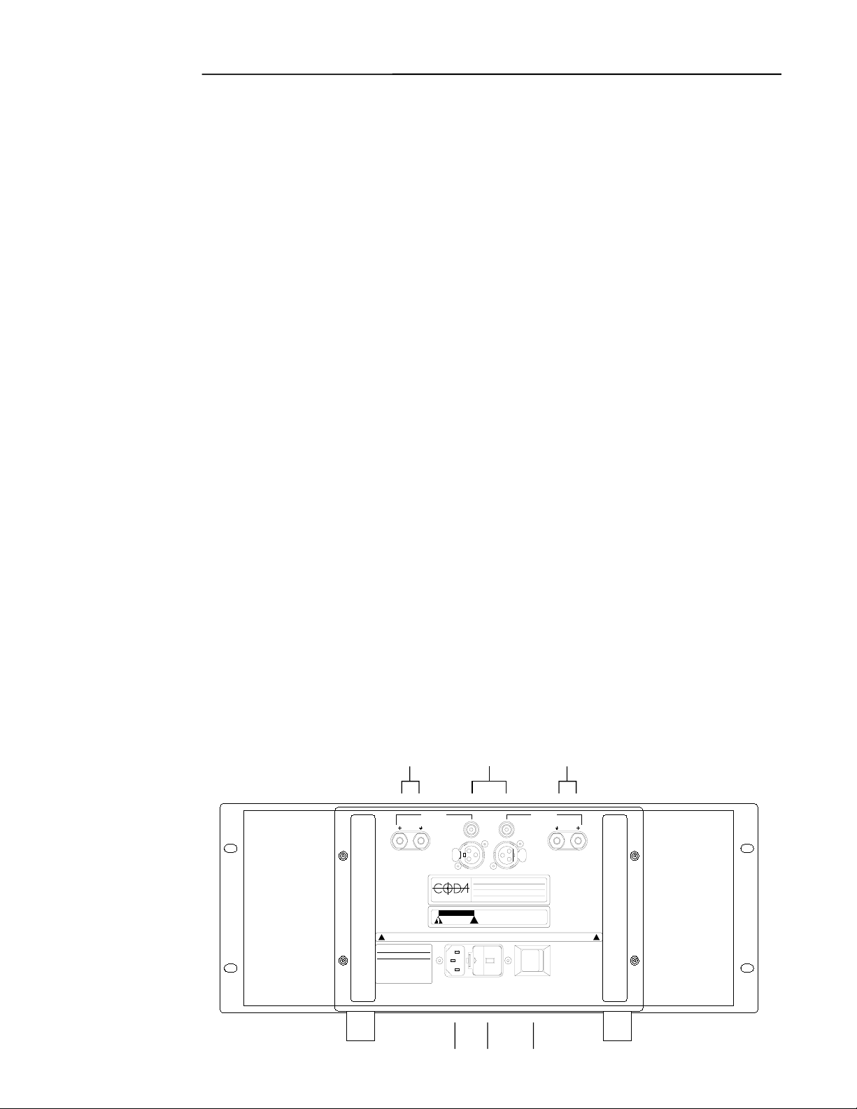
DETAILED INSTALLATION
4
I. Source-Output, Power Connections and Controls
The connectors and controls are clearly marked on the back panel of the AMPLIFIER
Note the correct left or right channel orientation. The function and channel markings on
the rear panel correspond to the front panel controls and their signal paths.
1.The UNBALANCE and BALANCED inputs should be attached to the appropriate
unbalanced and balanced outputs of a preamplifier either directly or through a
crossover or processor, as appropriate to the application.
2.The LEFT OUTPUT, RIGHT OUTPUT should be attached to the left and right speakers.
NOTE: THERE ARE NO OUTPUT FUSES SO AS TO INSURE A LOW OUTPUT IMPEDANCE.
SPEAKER PROTECTION IS LEFT TO THE SPEAKER MANUFACTER AS THEY WOULD BEST
KNOW HOW TO PROTECT THEIR SPEAKER.
3. The MAIN POWER switch, once all appropriate connectsions are made, may be left on
as the
AMPLIFIER draws a negligible amount of current when the BIAS is turned off.
4.The FUSE AND VOLTAGE SELECTOR houses a 5 X 20 slow blow fuse and voltage selector
cartridge. Should the fuse blow, contact a Coda dealer or call Coda directly. When
changing the fuse, or altering the voltage selection be sure this unit is disconected from
its AC power source.
5.The AC LINE INPUT should be attached to the power cable provided with the amplifier.
After making the appropriate connections insert the three prong safety plug into an
S5 SS
is properly connected, the
S
appropriate AC power source. Once the AMPLIFIER
power switch may be turned on and the led on the front panel will light indicating a ready
state.
BALANCED
MAIN POWER
RIGHT CHANNEL
2
DO NOT ALLOW AMPLIFIER
OUTPUTS TO COMMON
BETWEEN CHANNELS, OR
CONTACT CHASSIS OR
INPUT GROUNDS, OR TO BE
CONNECTED TO ANY ACTIVE
CURRENT SOURCE.
USE CLASS 1 WIRING
NOTE
DO NOT ATTACH BOTH
BALANCED AND UNBALANCED
CONNECTORS AT THE SAME TIME
!
2
LEFT CHANNEL
INPUTSOUTPUT OUTPUTINPUTS
UNBALANCED
BALANCED
PUSH
FOR CONTINUED PROTECTION
AGAINST SHOCK OR FIRE:
1. REPLACE FUSE WITH SAME
TYPE AND RATING
2. DO NOT EXPOSE THIS UNIT
TO RAIN OR MOISTURE
AC LINE FUSE CHART FUSE AND VOLTAGE SELECTOR
!
CODA CURRENT AMPLIFIER 20
VOLTAGE FUSE TYPE
100V 10 AMP SLOW BLOW 5 x 20mm
120V 10 AMP SLOW BLOW 5 x 20mm
220V 5 AMP SLOW BLOW 5 x 20mm
240V 5 AMP SLOW BLOW 5 x 20mm
TECHNOLOGIES INC.
CAUTION
CAUTION
WARNING
WARNING
AC LINE INPUT
~
SEE SERIAL TAG FOR
POWER REQUIREMENTS ,
REMOVE POWER CORD
BEFORE CHANGING FUSE
OR LINE VOLTAGE
1
MODEL
SERIAL NUMBER
VOLTAGE REQUIREMENT
!
FUSE VALUE -SEE FUSE CHART
VOLTAGE SELECTIONSEE OPERATION MANUAL
50/60 HZ VA
MANUFACTURED IN THE USA
TO PREVENT ELECTRIC SHOCK, DO NOT
REMOVE COVER. NO USER SERVICEABLE
PARTS INSIDE. REFER SERVICING TO
QUALIFIED SERVICE PERSONNEL.
120
OFF ON
UNBALANCED
PUSH
4
5
3

DETAILED INSTALLATION 5
II. Front Panel Control Functions and Indicators
1. The BIAS button turns on the bias and opens shunting relays that mute the input.
2. The INPUT SELECTOR button switches between the balanced and unbalanced inputs.
3. These LEDs when lit, indicate that the bias is activated in the AMPLIFIER S5.
4. This two color LED indicates that the main power is on. When it is red the balanced
inputs are in use. When it is yellow the unbalanced inputs are in use.
PRECISION BIAS CLASS A AMPLIFIER S5
BIAS INPUT
SELECTOR
1 2
LEFT
RIGHT
3
POWER
RED BAL/YELLOW UNBAL
4
Note: If a power interruption occurs to the system the AMPLIFIER S5 defaults to bias off.
 Loading...