

Coda S150, S250 Operation Manual
T E C H N O L O G I E S I N C .
INPUT BIAS
UNBAL./YELLOW
BALANCE/GREEN
AMPLIFIER SYSTEM
OPERATION MANUAL
SYSTEM VOLTAGE AMPLIFIER
S150
BIAS POWER BIAS
SYST EM CU RREN T AMPLI FIER
SAFETY PRECAUTIONS
INTRODUCTION
INSTALLATION CONNECTIONS
DETAILED INSTALLATION
DESIGN PHILOSOPHY
S250
BIAS POWER BIAS
SYST EM CU RREN T AMPL IFIE R
1
2
3
4
8
TECHNICAL DATA
CARE & HANDLING
SERVICING
WARRANTY
WARRANTY REGISTRATION
ADDRESS
11
12
13
22
23
24
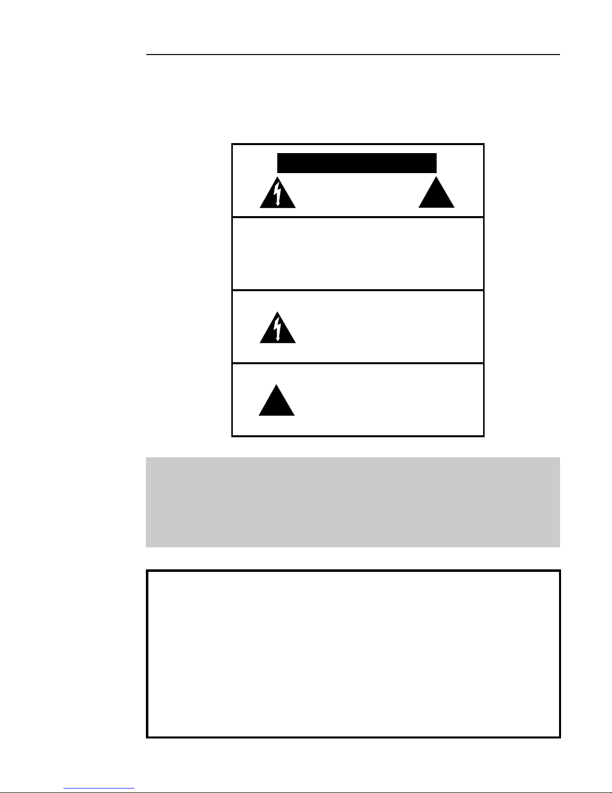
SAFETY PRECAUTIONS
CAUTION: TO PREVENT ELECTRIC
SHOCK, DO NOT REMOVE COVER.
NO USER SERVICEABLE PARTS
INSIDE, REFER SERVICING TO
QUALIFIED SERVICE PERSONNEL.
!
CAUTION
CAUTION
WARNING
WARNING
THIS SYMBOL IS TO ALERT YOU OF
THE PRESENCE OF UNINSULATED
DANGEROUS VOLTAGE WITHIN THE
UNIT'S ENCLOSURE THAT MAY BE OF
SUFFICIENT MAGNITUDE TO
CONSTITUTE A RISK OF ELECTRIC
SHOCK.
THIS SYMBOL IS INTENDED TO ALERT
YOU OF THE PRESENCE OF
IMPORTANT OPERATING AND
MAINTENANCE INSTRUCTIONS IN THE
LITERATURE ACCOMPANYING THE
UNIT.
!
1
WARNING: TO PREVENT FIRE OR SHOCK HAZARD, DO
NOT EXPOSE THIS UNIT TO RAIN OR
MOISTURE. TO AVOID ELECTRICAL SHOCK, DO
NOT OPEN THE UNIT. REFER SERVICING TO
QUALIFIED PERSONNEL.
CAUTION -
Never install or remove the power cord from the chassis
unless it has been disconnected from the AC power source
first.
Never pull on the power cord when removing it from an AC
-
power source. Grasp it by the plug.
Do not leave the power cord connected to an AC power
-
source unless it is connected to the unit.
-
It is recommend that during extended periods of non-use
that the units power cord be unplugged from its AC power
source.
Route the AC power cord so that it will not be damaged or
-
walked on.

INTRODUCTION
This amplifier is a precision device, designed in an effort to provide the listener with
unmatched sound quality, design, and construction. In order to operate your amplifier properly
and to realize all of the capabilities of the AMPLIFIER SYSTEMS, were commend that you
read this entire manual carefully.
2
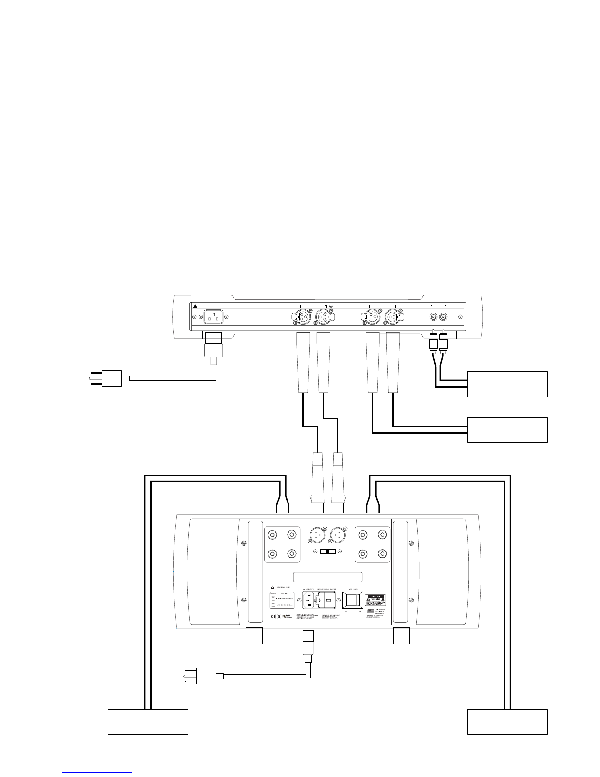
INSTALLATION CONNECTIONS
3
The first section of the installation instructions for the AMPLIFIER SYSTEM is a diagram of
the default configuration required to bring the amplifier into an operating mode. These brief
steps will allow you to begin operating your system. Make sure during installation that the
main AC power switch on the back of the CURRENT AMPLIFIER S150/250 is turned off, and
AC power connection to the VOLTAGE AMPLIFIER SV is interrupted. While the diagram may
be self explanatory, we strongly recommend that you read the detailed instructions following
this introductory section.
Note: 1. You may attach both XLR and RCA inputs to the SV at the same time.
2. Use only the supplied interconnect cables between the SV and the S150/250.
FOR CONTIMUED PROTECTION AGAINST
AC LINE INPUT
!
~
SEE SERIAL TAG FOR
POWER REQUIREMENTS
SHOCK OR FIRE HAZARD, DO NOT EXPOSE
THIS UNIT TO RAIN OR MOISTURE.
OUTPUT TO CODA CURRENT AMPS ONLY
LEFT RIGHT
PUSH
PUSH
BALANCED INPUT
LEFT RIGHT RIGHTLEFT
PUSH
PUSH
UNBALANCED INPUT
RIGHT
USE ONLY SPECIFIED FUSE TYPE
6
8
INPUT FROM SYSTEM VOLTAGE AMP ONLY
RIGHT LEFT/BRIDGED
PARALLEL SPLIT
120
PREAMPLIFIER
PREAMPLIFIER
LEFT
LEFT SPEAKER
RIGHT SPEAKER
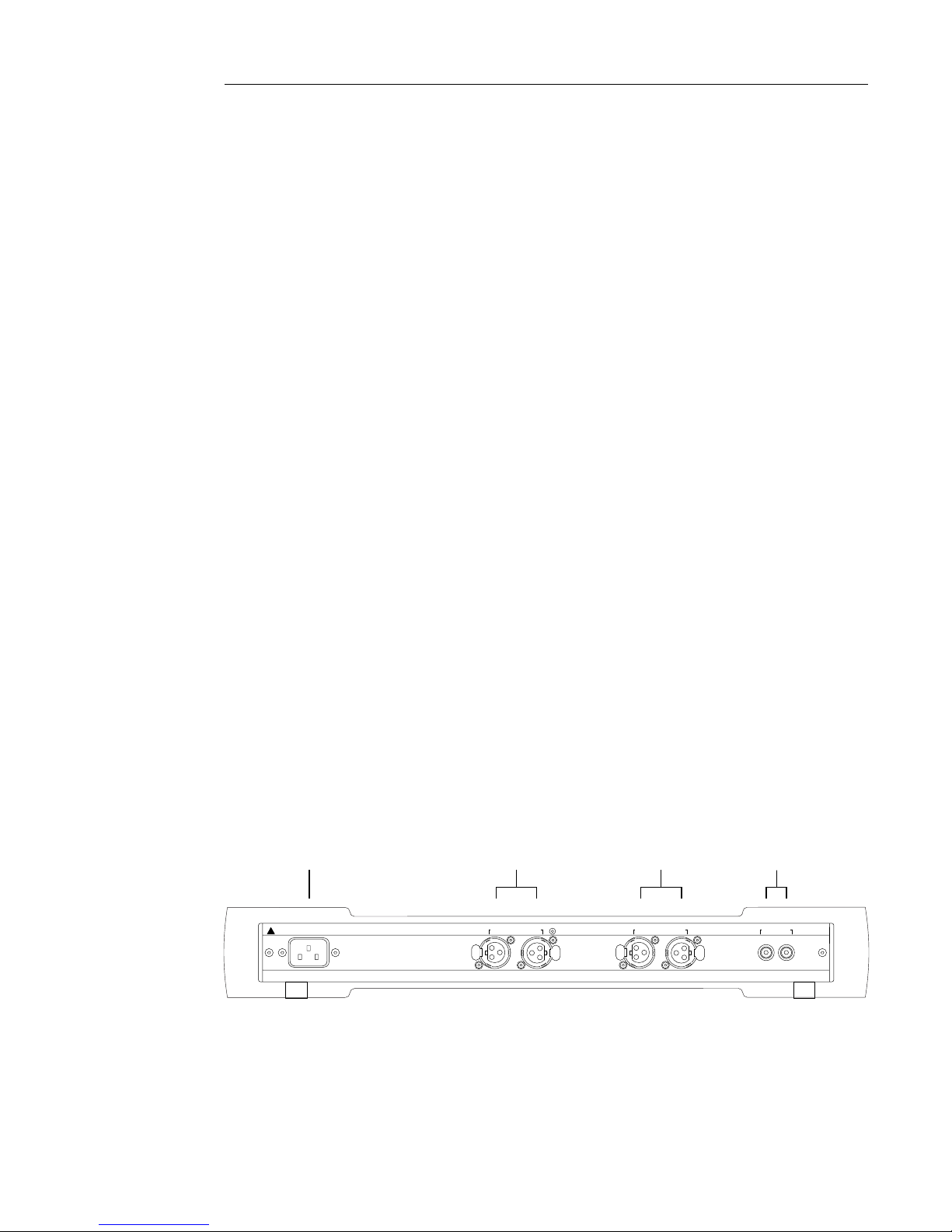
DETAILED INSTALLATION
4
II. Source-Output, Power Connections and Controls
The input and output connectors and controls are clearly marked on the rear lip of the top
cover for the VOLTAGE AMPLIFIER SV, and on the back panel of the CURRENT AMPLIFIER
S150/250. It is important to remember the correct left or right channel orientation. The
function and channel markings on the rear panel correspond to the front panel control and
their signal paths.
VOLTAGE AMPLIFIER SV
1. The UNBALANCED inputs should be attached to the unbalanced outputs of a preamplifier
either directly or through a crossover or processor, as appropriate to the application.
2. The BALANCED inputs should be attached to the balanced outputs of a preamplifier
either directly or through a crossover or processor, as appropriate to the application.
3. The OUTPUTS should be attached to the input of each CURRENT AMPLIFIER
S150/250 only.
WARNING: Set the SYSTEM SELECTOR to STANDBY before attaching or detaching the
interconnect cables between the VOLTAGE AMPLIFIER SV and the CURRENT AMPLIFIER
S150/250.
4. The AC LINE INPUT should be attached to the power cable provided with the voltage
amplifier. After making the appropriate connections and rotating the SYSTEM SELECTOR
control to the STANDBY position, insert the three prong safety plug into an appropriate AC
power source. Once the VOLTAGE AMPLIFIER SV is properly connected, the led on the
front panel will light indicating a ready state.
AC LINE INPUT
~
SEE SERIAL TAG FOR
!
POWER REQUIREMENTS
4
FOR CONTIMUED PROTECTION AGAINST
SHOCK OR FIRE HAZARD, DO NOT EXPOSE
THIS UNIT TO RAIN OR MOISTURE.
OUTPUT TO CODA CURRENT AMPS ONLY
LEFT RIGHT
PUSH
3
PUSH
2
BALANCED INPUT
LEFT RIGHT RIGHTLEFT
PUSH
PUSH
1
UNBALANCED INPUT
DETAILED INSTALLATION
5
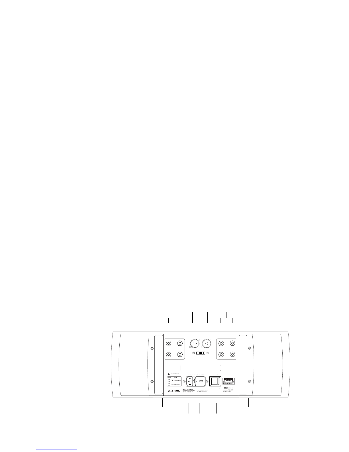
CURRENT AMPLIFIER S150/250
1. The OPERATION SELECTOR sets the operational mode between PARALLELED, or
SPLIT CHANNEL. The default position is SPLIT for the S150 and PARALLELED, for the
S250, for the alternate positions, see the SERVICING section of this manual.
2. The INPUTS should be attached to the VOLTAGE AMPLIFIER SV only.
3. The LEFT/CH A OUTPUT, RIGHT/CH B OUTPUT should be attached to the left and right
speakers.
NOTE: THERE ARE NO OUTPUT FUSES SO AS TO ENSURE A LOW OUTPUT
IMPEDANCE. SPEAKER PROTECTION IS LEFT TO THE SPEAKER MANUFACTURER AS
THEY WOULD BEST KNOW HOW TO PROTECT THEIR SPEAKER.
4. The MAIN POWER switch may be left on once all appropriate connections are made, as
the CURRENT AMPLIFIER S150/250 draws a negligible amount of current when the
SYSTEM SELECTOR control on the VOLTAGE AMPLIFIER SV is in the BIAS OFF position.
CAUTION- DURING EXTENDED PERIODS OF NON-USE TURN OFF THE MAIN POWER
SWITCH.
5. The FUSE AND VOLTAGE SELECTOR houses a 5 x 20 mm slow blow fuse and voltage
selector cartridge. Should the fuse blow contact Coda directly. When changing the fuse
altering the voltage selection be sure this unit is disconnected from its AC power source.
6. The AC LINE INPUT should be attached to the power cable provided. After making the
appropriate connections and setting the BIAS SELECTOR control on the VOLTAGE
AMPLIFIER SV to the BIAS OFF position, insert the three prong safety plug into an
appropriate AC power source. Once the CURRENT AMPLIFIER SV is properly connected,
the power switch may be turned on and the LED on the front panel will light indicating that the
bias is on.
3
RIGHT
2 2
1
INPUT FROM SYSTEM VOLTAGE AMP ONLY
RIGHT LEFT/BRIDGED
PARALLEL SPLIT
3
LEFT
USE ONLY SPECIFIED FUSE TYPE
6
8
120
6 5 4
DETAILED INSTALLATION
6
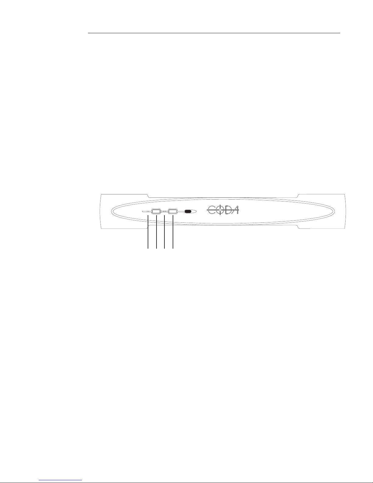
III. Front Panel Control Functions and Indicators
VOLTAGE AMPLIFIER SV
The INPUT SELECTOR control [1] selects the desired input to the Voltage Amplifier SV the
bicolor LED [4] indicates the selected input. GREEN indicates the balanced input has been
selected and YELLOW indicates the unbalanced input has been selected.
The BIAS control [2] enables the on the bias current and opens shunting relays that mute the
input for the CURRENT AMPLIFIER S150/250. This BIAS ON state is indicated by the BLUE
LED [3].
Input selection and Bias On/Off functions are remote-controllable. Please refer to the Remote
Control manual addendum provided with the optional Coda remote control, which is available
from Coda.
UNBAL./YELLOW
BALANCE/GREEN
INPUT BIAS
SYSTEM VOLTAGE AMPLIFIER
21 34
Note: If a power interruption occurs to the system, immediately turn the BIAS power OFF on
the front of the SV. The resumption of power will cause no noise pulses in the Amplifier
System S150/250. However, some sources may produce high output voltages on turn on,
which may cause damage to the amplifier or speakers.
DETAILED INSTALLATION
7
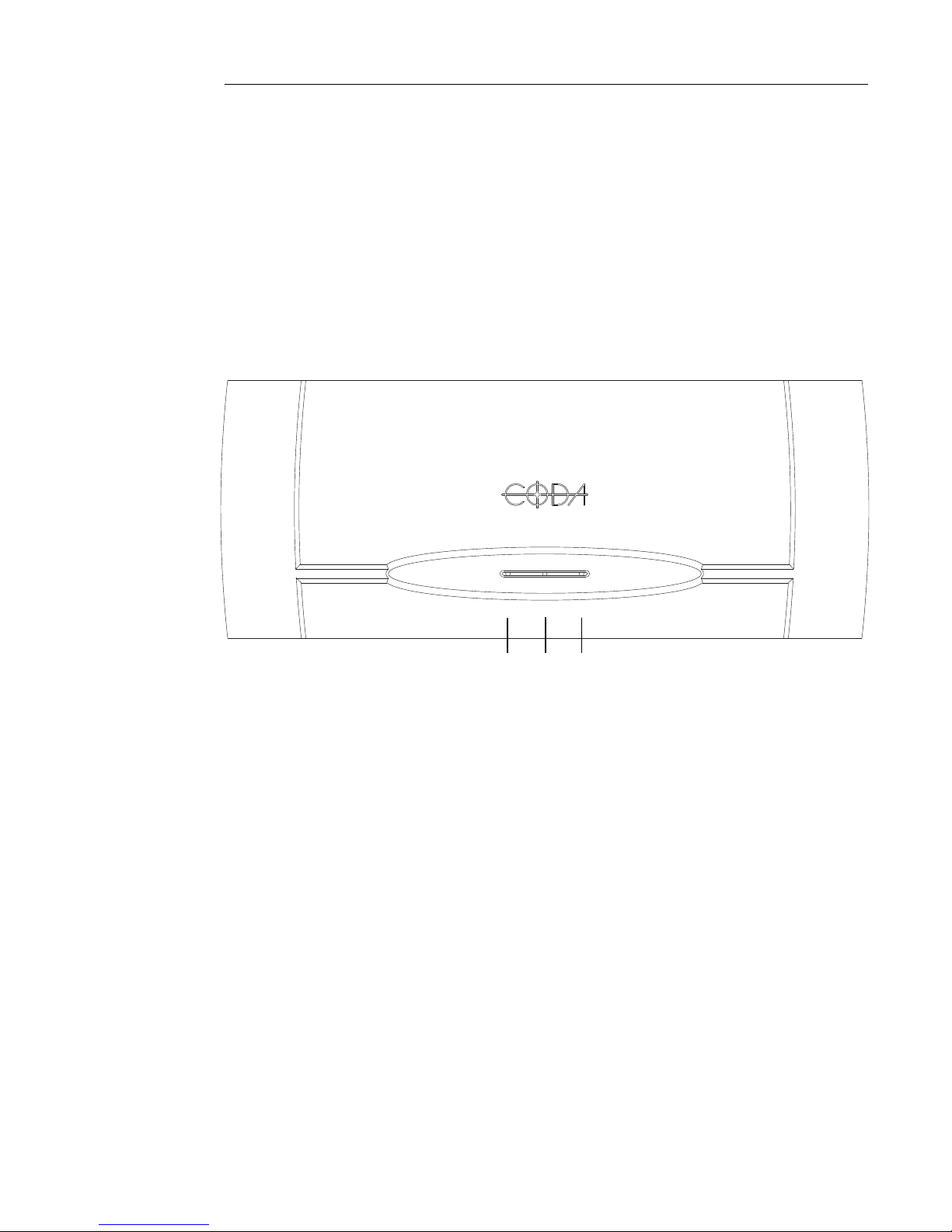
CURRENT AMPLIFIER S150/250
The BIAS LEDs [1], when lit, indicate that the bias is activated, and shunting relays that mute
the input from the VOLTAGE AMPLIFIER SV are open.
The POWER LED [2], when lit, indicates that the CURRENT AMPLIFIER S150/250 is in an
operational state.
S150
BIAS POWER BIAS
SYS TEM C URRE NT AMP LIFI ER
1
1
2
 Loading...