

Coda C5 User Manual
Coda Audio
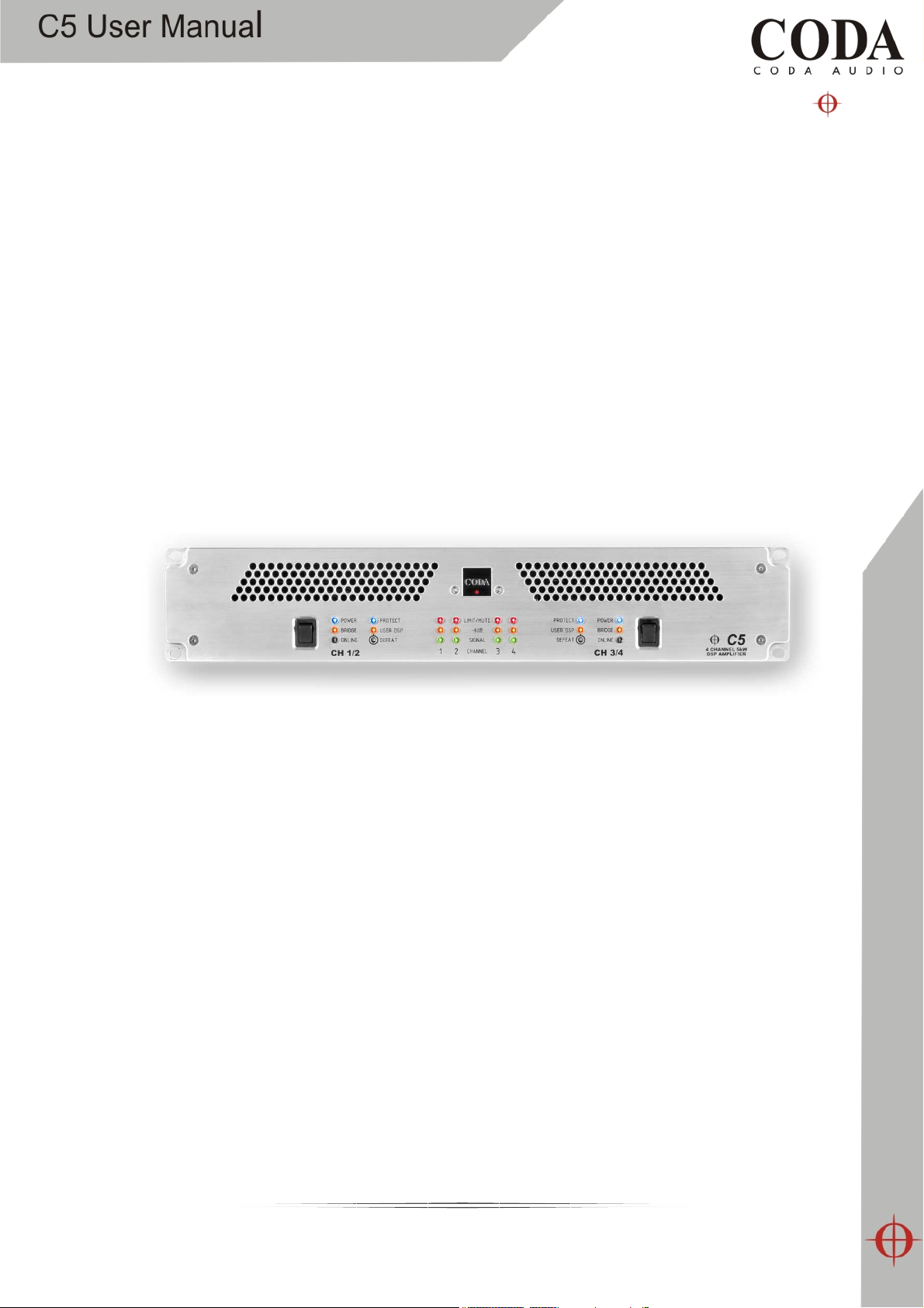
C5 DSP amplifier
User Guide version 1
1

Important Safety Information
Please read carefully and keep the following instructions and safety information. Heed all
warnings and follow all instructions.
• Do not remove covers. There are no user serviceable parts inside; please
refer servicing to qualified service personnel.
• This equipment must be earthed.
• Protect the power cord from being walked on or pinched, particularly at plugs,
convenience receptacles and the point where they exit from the apparatus.
• Only use attachments/accessories specified by the manufacturer.
• Servicing is required when the apparatus has been damaged in any way, such as
the power supply cord or plug is damaged, liquid has been spilled or objects have
fallen into the apparatus, the apparatus has been exposed to rain or moisture, does
not operate normally, or has been dropped.
Regulatory Compliance
This product complies with both the EMC Directive (89/336/EEC) and the Low Voltage
Directive (73/23/EEC) as issued by the Commission of the European Community.
Compliance with these directives imply conformity with the following European standards:
• EN60065 Product safety
• EN55103-1 Electromagnetic Interference (Emission)
• EN55103-2 Electromagnetic Susceptibility (Immunity)
This product is intended for operation in the E2 (commercial & light industrial) and E3
(urban outdoors) Electromagnetic Environments.
2

Table of Contents
Important Safety Information .................................................................................................. 2
Regulatory Compliance .................................................................................................... 2
Thanks and Unpacking ............................................................................................................ 5
Introduction and Key Features ................................................................................................. 6
Front Panel .......................................................................................................................... 13
Power Switch ................................................................................................................ 13
Power ON indicator ........................................................................................................ 13
Bridged Mode indicator .................................................................................................. 13
Control Software Online indicator .................................................................................... 13
Protect ......................................................................................................................... 14
User DSP indicator ......................................................................................................... 14
User DSP Setting Defeat button ...................................................................................... 14
Input Signal Indicators ................................................................................................... 14
Rear Panel ........................................................................................................................... 15
Power Inlet ................................................................................................................... 15
Audio Input Connectors ................................................................................................. 15
Audio Output Connectors ............................................................................................... 15
Communications Port Connections .................................................................................. 16
Mechanical Installation ............................................................................................................ 7
AC Power Connection .............................................................................................................. 9
Audio Connections ................................................................................................................ 10
Using unbalanced connections ........................................................................................ 11
Amplifier output connections .......................................................................................... 11
100V line operation ............................................................................................................... 12
C-Net Amplifier Control Panel ................................................................................................. 17
Amplifier Channels ......................................................................................................... 18
User Controls ................................................................................................................ 18
Monitoring Section (MonIcon) ......................................................................................... 19
User DSP ...................................................................................................................... 19
Main Control Panel ........................................................................................................ 20
Hidden Controls............................................................................................................. 22
Saving & Recalling Data ................................................................................................. 22
Loading Factory Presets ................................................................................................. 22
Tool Bar ....................................................................................................................... 23
Keyboard Shortcuts ....................................................................................................... 23
Audio Processing ........................................................................................................... 24
Equalisation Filters......................................................................................................... 25
Bridge Mode ................................................................................................................. 25
Protection ..................................................................................................................... 26
Limiters ........................................................................................................................ 26
Indication .....................................................................................................................
25
3

EQ and Filter Response Graphs .............................................................................................. 27
Signal Processing Block Diagram ........................................................................................ 30
Technical Specifications ..................................................................................................... 31
4

Thanks and Unpacking
Thank you for choosing a Coda Audio C5 DSP amplifier system for your application. Please
spare a little time to study the contents of this manual, so that you obtain the best
possible performance from this unit.
All Coda Audio products are carefully engineered for world-class performance and
reliability. If you would like further information about this or any other Coda Audio
product, please contact us. We look forward to helping you in the near future.
Unpacking the Coda Audio C5 DSP amplifier
After unpacking the unit, please check carefully for damage. If damage is found, please
notify the carrier concerned at once. You, the consignee, must instigate any claim. Please
retain all packaging in case of future re-shipment.
5
Introduction and Key Features
Introduction
The C5 DSP amplifier systems from Coda Audio integrate light-weight power supplies, high
power sonically transparent class D amplifiers, complete system monitoring and a fully
featured USB or network controlled 24 bit 96kHz DSP processing platform as standard.
Key features
• One or two dual amplifier sections : two or four channels
• Each section is completely independent with discrete PSU, amplifier and DSP
• Fully featured PC control and telemetry of single devices or networks as standard
• Coda Audio class leading Class D amplifier stages
• Minimal signal path and refined DSP algorithms for clean, dynamic and musical
audio performance
6
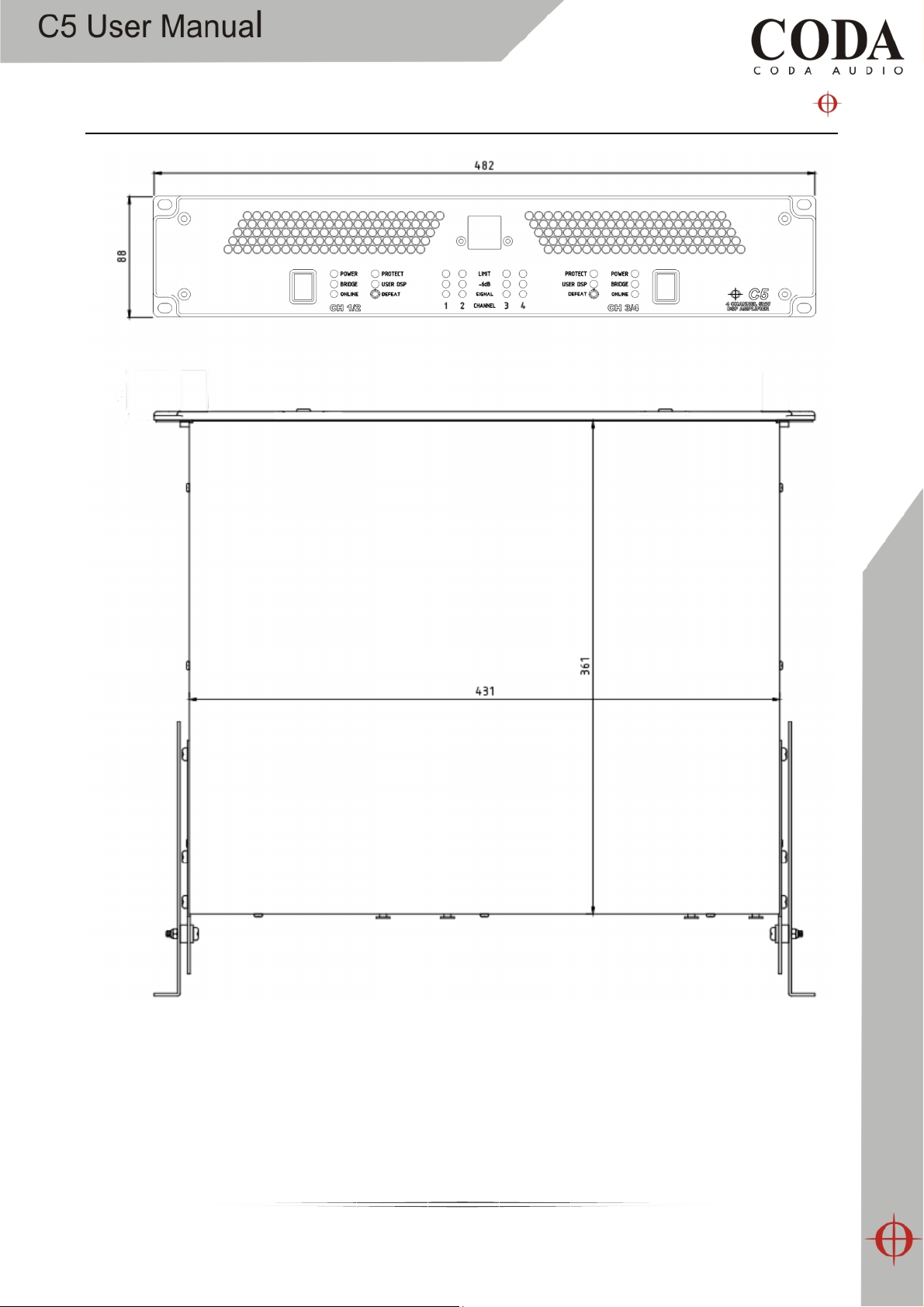
Mechanical Installation
The C5 DSP amplifier system is designed to be mounted in a standard 19” rack enclosure.
Where the amplifier is used in a fixed installation, it is possible to use only the front panel
19” rack mounting holes to mount it in a standard rack enclosure. If the amplifier is
mounted in a mobile rack it is recommended that the rear rack mounting kit is fitted so
7

the amplifier can be well supported. Damage caused by insufficient support is not covered
by the warranty.
To prevent damage to the front panel it is recommended that plastic cups or washers are
fitted underneath the rack mounting bolt heads.
It is possible to mount multiple C5 amplifiers without ventilation gaps between them but it
is essential that an unobstructed flow of clean air is available from the back of the unit to
the front. It is important the neither the air intakes at the rear of the unit or the exhaust
vents at the front are covered.
The amplifier should never be exposed to rain or moisture during operation or storage. If
the unit does come into contact with moisture, remove the AC power cord immediately
and leave it in a dry and warm location to dry out.
Note that when any equipment is taken from a cold location into a hot humid one,
condensation may occur inside the device. Always allow time for the equipment to attain
the same temperature as its surrounding environment before connecting the AC power
cord.
8

AC Power Connection
WARNING! THIS APPLIANCE MUST BE GROUNDED.
The amplifier must always be connected using a 3-wire, grounded AC supply. The
framework of the rack mount enclosure should also be connected to the same grounding
circuit. The unit should never be operated unless the AC power cable ground is correctly
terminated; this is important for personal safety and for control of the system grounding.
The amplifier is supplied with a Neutrik PowerConTM type locking AC power connector. Use
only an AC power cord with a correctly terminated PowerConTM type connector to make
the connection to the mains power supply.
The C5 amplifiers are designed to operate on 50/60 Hz AC power. The power supply
sections automatically configure themselves for either 115V or 230V nominal voltage at
turn on. The amplifiers will operate over an extended range of supply voltages from;
nominal 115V / 230V +/- 10%.
Note that whilst the amplifier will operate correctly at voltages indicated, the specified
output power will only be achieved when operating with the stated nominal voltages.
9
Audio Connections
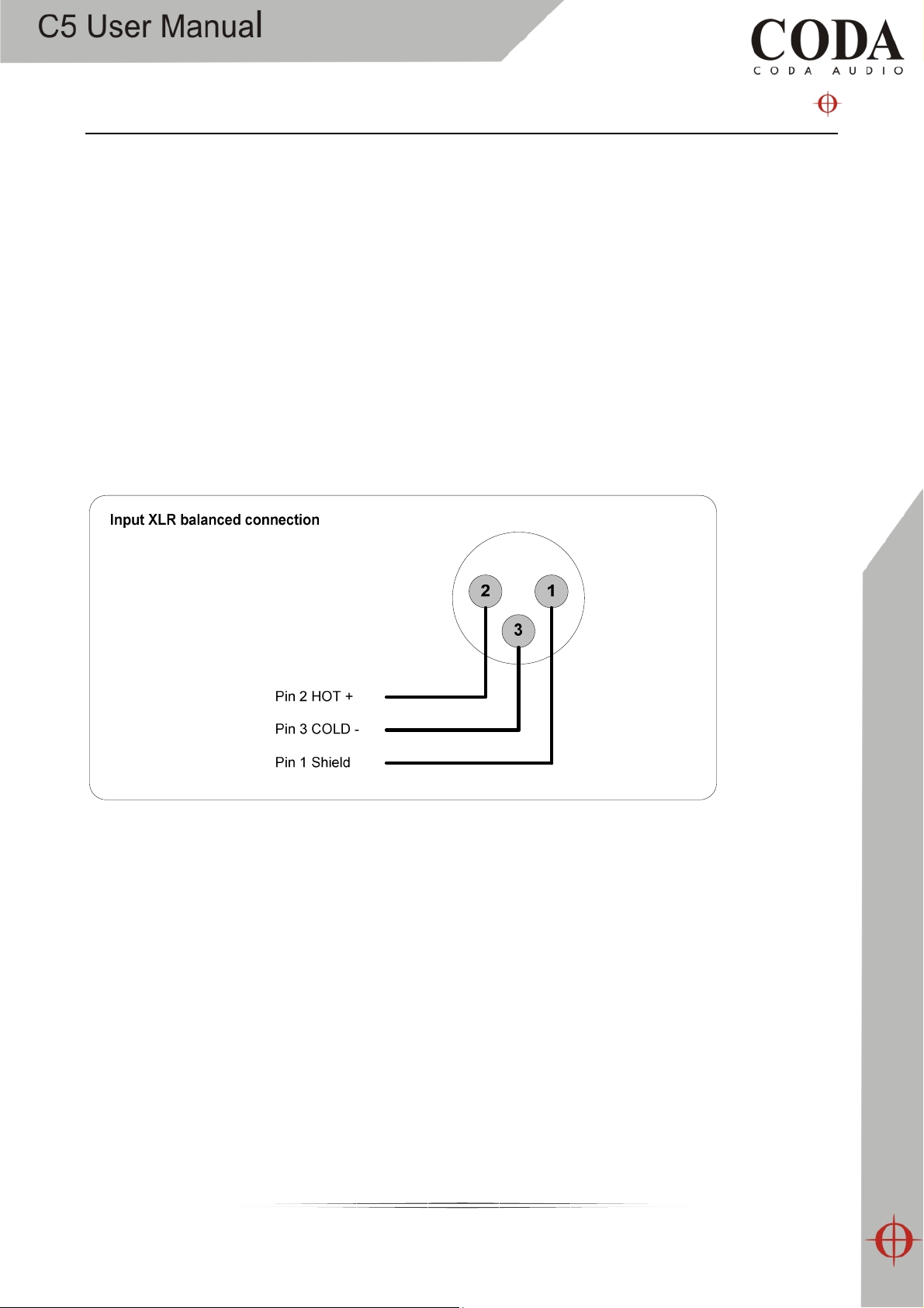
For each amplifier channel there are female and male XLR input connectors which are
wired in parallel. Typically the female connector is used for the audio input, the male XLR
connector being available to link the same audio signal to another amplifier channel.
The HOT, + or ‘in phase’ connection should be made to pin 2 of the XLR connector.
The COLD, - or ‘out of phase’ connection should be made to pin 3 of the XLR connector.
Pin 1 of the XLR connectors is internally connected to the chassis. The screen of the input
cable should always be connected to one of these points to ensure that EMC performance
and regulations are met. The cable shield ground should also be connected to the source
device which is providing the input signal to the amplifiers.
10
 Loading...