

Coda AMPLIFIER 15.0 Operation Manual
TECHNOLOGIES INC.
CODA TE CHNOLOG IE S INC.
RCA/YL
LEFT RIGHTXLR/GN
BIAS INPUT
PR ECI SION CLASS A AMPLI FIE R
15.0
AMPLIFIER 15.0
OPERATION MANUAL
SAFETY PRECAUTIONS
INTRODUCTION
INITIAL SETUP
DETAILED INSTALLATION
DESIGN PHILOSOPHY
TECHNICAL DATA
CARE AND HANDLING
WARRANTY & DISCLAIMER
WARRANTY REGISTRATION
1
2
3
4
9
12
13
14
15
SAFETY PRECAUTIONS 1
CAUTION
CAUTION
WARNING
WARNING
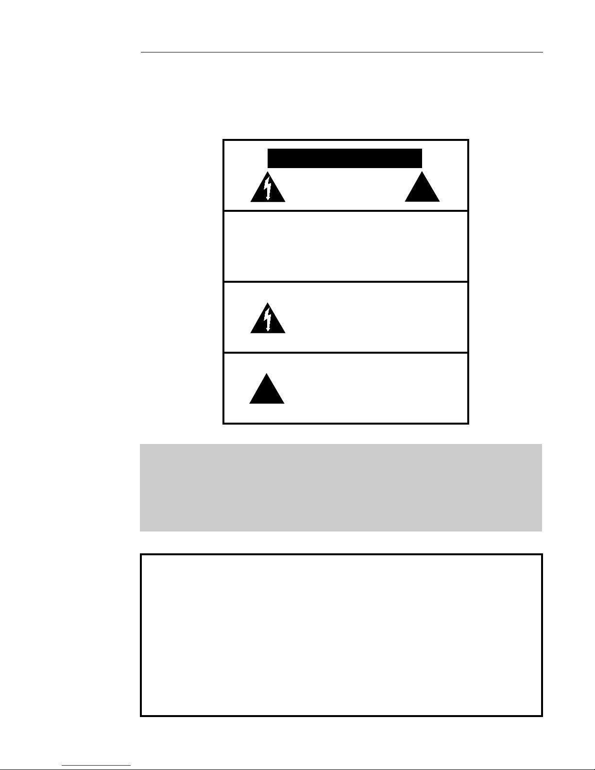
CAUTION: TO PREVENT ELECTRIC SHOCK,
DO NOT REMOVE COVER. NO USER
SERVICEABLE PARTS INSIDE, REFER
SERVICING TO QUALIFIED SERVICE
PERSONNEL.
THIS SYMBOL IS TO ALERT YOU OF THE
PRESENCE OF UNINSULATED DANGEROUS VOLTAGE WITHIN THE UNIT'S
ENCLOSURE THAT MAY BE OF SUFFICIENT MAGNITUDE TO CONSTITUTE A
RISK OF ELECTRIC SHOCK.
!
WARNING:
CAUTION -
THIS SYMBOL IS INTENDED TO ALERT
YOU OF THE PRESENCE OF IMPORTANT
OPERATING AND MAINTENANCE
!
TO PREVENT FIRE OR SHOCK HAZARD, DO NOT
EXPOSE THIS UNIT TO RAIN OR MOISTURE. TO
AVOID ELECTRICAL SHOCK, DO NOT OPEN THE
UNIT. REFER SERVICING TO QUALIFIED PERSONNEL.
Never install or remove the power cord from the chassis
unless it has been disconnected from the AC power source
first.
Never pull on the power cord when removing it from an AC
-
power source. Grasp it by the plug.
Do not leave the power cord connected to an AC power
-
source unless it is connected to the unit.
-
It is recommended that during extended periods of nonuse
the unit's power cord be unplugged from its AC power
source.
Route the AC power cord so that it will not be damaged or
-
walked on.
INSTRUCTIONS IN THE LITERATURE
ACCOMPANYING THE UNIT.

INTRODUCTION 2
Thank you for purchasing the AMPLIFIER 15.0.
This amplifier is a precision device, designed in an effort to provide
the listener with unmatched sound quality through superb design
and construction.
Although its operation is fairly simple, in order to operate your
amplifier properly and to realize all of the capabilites of the
AMPLIFIER 15.0 we recommend that you read this entire manual
carefully.
INITIAL SETUP 3
WARNING: Please ensure that the power switch is turned OFF while you are connecting the
amplifier. Connecting or disconnecting cables while the amplifier is powered on could
cause damage to your speakers.
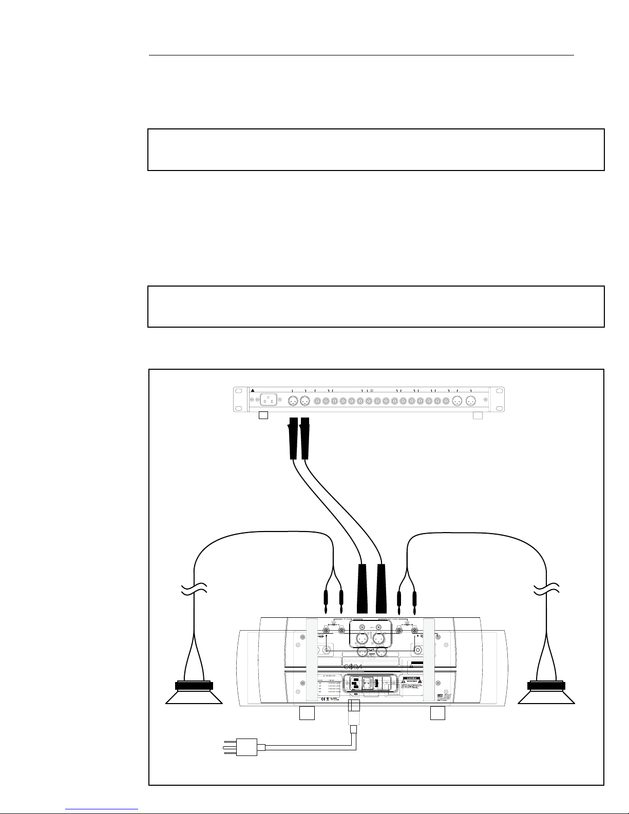
The diagram below shows the default connections necessary to operate the AMPLIFIER 15.0
as a stereo amplifier. This is the simplest and most common mode of operation, and the
quickest way to get started. Once these connections are made you can turn the power
switch on, enable the bias from the front panel and start listening to your amplifier.
For simplicity this diagram shows an audio configuration using balanced interconnects. This
is the default input mode of the amplifier. Unbalanced operation requires that you set the
appropriate input mode as detailed on page 5.
NOTE: Ensure that the mode switch located between the input jacks on the rear of the
amplifier is set to the stereo position for normal operation. Bridged operation is explained on
page 7.
Stereo Amplifier Configuration
FOR CONTINUED PROTECTION AGAINST
AC LINE INPUT
~
SEE SERIAL TAG FOR
!
POWER REQUIREMENTS
SHOCK OR FIRE HAZARD,DO NOT EXPOSE
THIS UNIT TO RAIN OR MOISTURE.
UNBALANCED OUTPUT
RIGHTLEFT
LEFT SPEAKER RIGHT SPEAKER
PREAMPLIFIER
PROCESSOR
IN
RIGHTLEFT
LEFT CHANNEL
UNBALANCED
BALANCED
READ THE BRIDGING SECTION OF THE OPERATING MANUAL OR CONTACT YOUR CODA AUTHORIZED
TECHNOLOGIES INC.
~
SEE SERIAL TAG FOR POWER
REQUIREMENTS, REMOVE POWER
CORD BEFORE CHANGING
FUSE OR LINE VOLTAGE
OUT
IN
RIGHTLEFTRIGHTLEFT
INPUTS
INPUTS
UNBALANCED
BRIDGED
INPUTS
PUSH PUSH
BALANCED
INPUTS
PUSH
MODE
BRIDGED MODE
STEREO
DEALER TO SET THE BRIDGING SWITCHES
BRIDGED
MODEL
SERIAL NUMBER
VOLTAGE REQUIREMENT
POWER REQUIREMENT
MANUFACTURED IN THE USA
AC LINE INPUT
FUSE AND VOLTAGE SELECTOR
12
0
AC LINE INPUT MAIN POWER FUSE / VOLTAGE SELECTOR
SEE SERIAL TAG FOR POWER REQUIREMENTS.
REMOVE POWER CORD BEFORE CHANGING FUSE OR LINE VOLTAGE.
FUSE VALUE -SEE FUSE CHART
VOLTAGE SELECTIONSEE OPERATION MANUAL
VIDEO
FOR CONTINUED PROTECTION AGAINST
SHOCK OR FIRE:
FOR CONTINUED PROTECTION
REPLACE FUSE WITH SAME TYPE AND
RATING. DO NOT EXPOSE THIS UNIT TO
AGAINST SHOCK OR FIRE:
RAIN OR MOISTURE
1. REPLACE FUSE WITH SAME
TYPE AND RATING
2. DO NOT EXPOSE THIS UNIT
TO RAIN OR MOISTURE
AC LINE FUSE CHART
!
VOLTAGE FUSE TYPE
100V
12 AMP SLOW BLOW 5 x 20mm
120V
220V
6 AMP SLOW BLOW 5 x 20mm
240V
16 AMP
16 AMP
8 AMP
8 AMP
AMPLIFIER 15.0
MONITOR
OUT
UNBALANCED
INPUTS
UNBALANCED
BALANCED
PUSH
BALANCED
VA
MAIN POWER
230
OFF ON
RIGHTLEFTRIGHTLEFT
RIGHT CHANNEL
DO NOT CONNECT AMPLIFIER OUTPUT
TERMINALS TOGETHER. CONNECT
AMPLIFIER OUTPUT TERMINALS ONLY TO
SPEAKERS.
HZ
VIDEO
RIGHTLEFT
CAUTION
CAUTION
WWARNING
TO PREVENT ELECTRIC SHOCK, DO NOT
REMOVE COVER. NO USER SERVICEABLE
PARTS INSIDE. REFER SERVICING TO
QUALIFIED SERVICE PERSONNEL.
DO NOT ALLOW AMPLIFIER OUTPUTS
TO COMMON BETWEEN CHANNELS,
OR CONTACT CHASSIS OR INPUT
GROUNDS, OR TO BE CONNECTED
TO ANY ACTIVE CURRENT SOURCE.
ARNING
TUNER
RIGHTLEFT
NOTE
UNBALANCED INPUT
COMPACT DISC
RIGHTLEFT
RIGHTLEFT
!
!
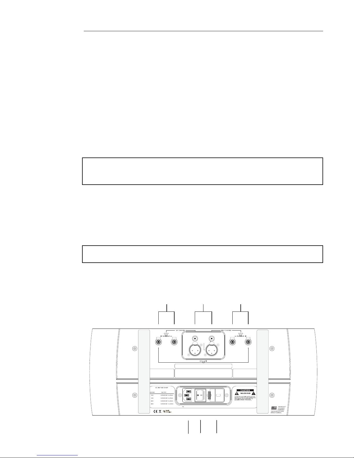
DETAILED INSTALLATION 4
I. Connections
The connectors and controls are clearly marked on the back panel of the amplifier.
Note the correct left or right channel orientation. The function and channel markings on
the rear panel correspond to the front panel controls and their signal paths.
1. The unbalanced and balanced inputs should be attached to the
appropriate unbalanced and balanced outputs of a preamplfier either directly
or through a crossover or processor, as appropriate to the application.
2. The left output and right output should be attached to the left and right speakers
respectively.
WARNING: There are no fuses on the amplifier’s outputs in order to cut down on
output impedance effects. Speaker protection is left to the manufacturer of your
speakers, as they would best know how to protect their product.
3. The AC line input should be connected to an AC outlet with the power cable
provided with the amplifier.
4. The fuse and voltage selector unit houses a 5x20mm slow-blow fuse and a voltage
selector cartridge. Ensure that the voltage, visible through a small window next to the
AC input, is set to the appropriate voltage for your country. When changing voltages,
ensure that the power cable is disconnected from the amplifier.
NOTE: If the fuse in your amplifier blows, contact a Coda dealer or call Coda
directly before attempting to use the amplifier again.
5. The power switch can usually be left on when the amplifier is functioning correctly.
With the bias disabled the amplifier will draw negligible current and can thus be left in
“standby” indefinitely.
2
UNBALANCED
3. The MAIN POWER switch, once all appropriate connections are made, may be left on
as the AMPLIFIER S5.5 draws a negligible amount of current when the BIAS is turned off.
4.The FUSE AND VOLTAGE SELECTOR houses a 5 X 20 slow blow fuse and voltage selector
cartridge. Should the fuse blow, contact a Coda dealer or call Coda directly. When
changing the fuse, or altering the voltage selection be sure this unit is disconnected from
FOR CONTINUED PROTECTION AGAINST
SHOCK OR FIRE:
REPLACE FUSE WITH SAME TYPE AND
RATING. DO NOT EXPOSE THIS UNIT TO
RAIN OR MOISTURE
BALANCED
READ THE BRIDGING SECTION OF THE OPERATING MANUAL OR CONTACT YOUR CODA AUTHORIZED
1
INPUTS
BRIDGED
INPUT
PUSH PUSH
BRIDGED MODE
DEALER TO SET THE BRIDGING SWITCHES
2
INPUTS
UNBALANCED
BALANCED
DO NOT CONNECT AMPLIFIER OUTPUT
TERMINALS TOGETHER. CONNECT
AMPLIFIER OUTPUT TERMINALS ONLY TO
SPEAKERS.
it's AC power source.
16 AMP
5.The AC LINE INPUT should be attached to the power cable provided with the amplifier.
After making the appropriate connections insert the three prong safety plug into an
appropriate AC power source. Once the AMPLIFIER S5 is properly connected, the
16 AMP
8 AMP
8 AMP
AC LINE INPUT MAIN POWER FUSE / VOLTAGE SELECTOR
SEE SERIAL TAG FOR POWER REQUIREMENTS.
REMOVE POWER CORD BEFORE CHANGING FUSE OR LINE VOLTAGE.
230
power switch may be turned on and the LED on the front panel will light indicating a ready
state.
5
3
4
 Loading...