

Page 1

Page 2
User’s Manual
PowerTALK 101 - Ethernet to Serial converter
Page 3

PowerTALK 101
PowerTALK 101
Configuration, usage and testing guide for PowerTALK 101 communications equipment.
Manual release date: 20 October 1998
Manual Release 2
Supersedes manual, release 1, 15 Oct 98
Supersedes preliminary manual, rev 0.3
Supersedes preliminary manual, rev 0.2
Supersedes preliminary manual, rev 0.1
PowerTALK 101 Firmware release 1.00
PT.EXE Configuration software, release 1.01
Contact address:
Cocoon Creations cc
PO Box 380
Groenkloof
0027
South Africa
Internet: www.cocoon-creations.com
Support: powertalk@cocoon-creations.com
2
Page 4

PowerTALK 101
Table of Contents
TABLE OF CONTENTS ............................................................................................................................. 3
FOREWORD................................................................................................................................................5
INTRODUCTION........................................................................................................................................ 7
B
RIEF DESCRIPTION..................................................................................................................................... 7
PC
CONFIGURATION TOOL PT.EXE & PT98.EXE...................................................................................... 7
Y
EAR 2000.................................................................................................................................................. 7
O
RDERING OPTIONS..................................................................................................................................... 8
Default specifications for PowerTALK 101:...........................................................................................8
Custom specifications for PowerTALK 101:.......................................................................................... 8
A
VAILABLE POWERTALK 101 MODELS ..................................................................................................... 8
D
ISCLAIMER ................................................................................................................................................ 8
POWERTALK 101 OVERVIEW ............................................................................................................... 9
F
EATURE OVERVIEW.................................................................................................................................... 9
F
UNCTIONAL OVERVIEW OF POWERTALK 101......................................................................................... 10
CHEMATIC OVERVIEW OF POWERTALK 101........................................................................................... 11
S
N
ETWORK TOPOLOGY OVERVIEW OF POWERTALK 101 ........................................................................... 12
PHYSICAL PROPERTIES....................................................................................................................... 13
P
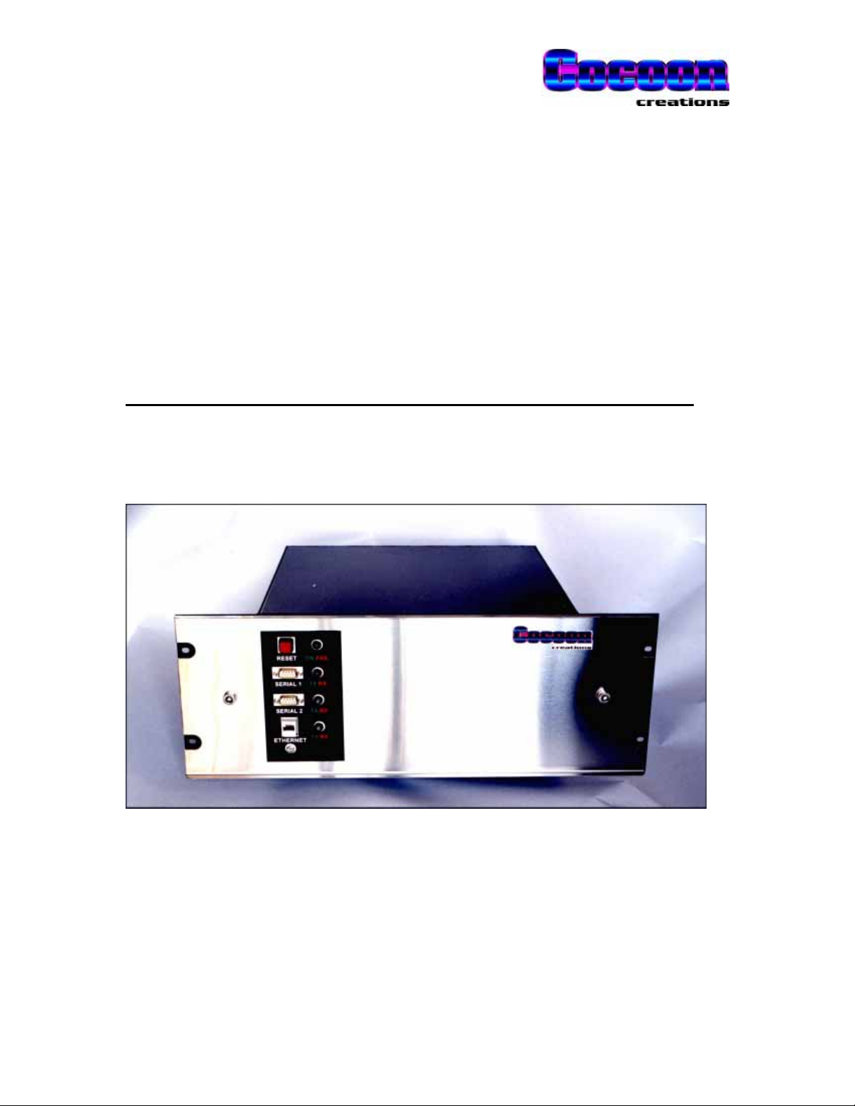
OWERTALK 101 PICTURE....................................................................................................................... 13
LED,
PLUG AND SWITCH LAYOUT.............................................................................................................. 13
EVICE AND TERMINAL IDENTIFICATION................................................................................................... 14
D
D
IMENSIONS.............................................................................................................................................. 14
R
EAR DIN RAIL......................................................................................................................................... 14
A
DDITIONAL POWER SUPPLY OUTPUTS ...................................................................................................... 14
F
ACE PLATE CARE & MAINTENANCE ......................................................................................................... 14
I
NTERNAL CONNECTIONS AND LAYOUT ..................................................................................................... 15
F
USES & LINKS.......................................................................................................................................... 16
B
ATTERY REPLACEMENT........................................................................................................................... 16
J
UMPER SETTINGS...................................................................................................................................... 17
Power supply board.............................................................................................................................. 17
Communications processor board................................................................................................... ..... 18
ELECTRICAL CONNECTION TO POWERTALK ............................................................................. 19
E
XTERNAL WIRING ................................................................................................................................... 19
E
ARTH WIRING.......................................................................................................................................... 19
I
SOLATION IN THE POWERTALK 101 BOX ................................................................................................ 20
POWERTALK 101 SPECIFICATIONS.................................................................................................. 21
M
AIN PROCESSOR COMPONENT ................................................................................................................. 21
M
AIN POWER SUPPLY ................................................................................................................................21
OWERTALK 101 SPECIFICATIONS........................................................................................................... 22
P
P
OWERTALK 101..................................................................................................................................... 22
CONNECTING POWERTALK 101 TO A NETWORK........................................................................ 25
Q
UICK START GUIDE.................................................................................................................................. 25
3
Page 5

PowerTALK 101
Power Supply........................................................................................................................................ 25
Networking ........................................................................................................................................... 25
HANGING MORE ADVANCED PARAMETERS USING PT.EXE...................................................................... 26
C
P
ASSWORDS............................................................................................................................................... 27
PT.EXE – P
PT.EXE
OWERTALKCOMMAND LINE INTERFACE .............................................................................. 28
EXAMPLES................................................................................................................................... 28
Confirm your PC IP address................................................................................................................ 28
List all available PowerTALK units...................................................................................................... 29
Set a PowerTALK unit name................................................................................................................. 29
Change some parameters ..................................................................................................................... 29
Change a port/channel allocation ........................................................................................................ 29
Accept all changes................................................................................................................................ 29
P
OWERTALK98–WINDOWS GUI SOFTWARE......................................................................................... 30
P
OWERTALK 98 EXAMPLES ..................................................................................................................... 31
ETWORK TOPOLOGY............................................................................................................................... 32
N
P
OWERTALK 101 CONFIGURATION.......................................................................................................... 34
P
RE-CONNECT CONFIGURATION................................................................................................................. 34
Serial connection cables....................................................................................................................... 34
Network connection: IP address setting............................................................................................... 35
Other settings on PowerTALK 101 ....................................................................................................... 36
C
ONNECTING TO THE PHYSICAL NETWORK................................................................................................ 36
10-BASE-T............................................................................................................................................ 36
COMMISSIONING AIDS......................................................................................................................... 37
LED
INDICATIONS..................................................................................................................................... 37
Normal LED indications on face plate:................................................................................................37
Indications on inside of box, only visible when cover is removed:....................................................... 37
T
ESTS........................................................................................................................................................ 38
Tests using standard networking protocols:......................................................................................... 38
Tests available using PT.EXE............................................................................................................... 38
Tests available using PowerTALK 98 under Windows 95 or NT.......................................................... 38
T
ESTING PROCEDURE................................................................................................................................. 39
ASY FUNCTIONALITY TEST -LOOPBACK TEST: ........................................................................................ 40
E
S
ETTING AND CONFIGURING POWERTALK 101........................................................................................ 42
P
RACTICAL CONNECTION EXAMPLE –ADDRESS TYPE SERIAL DEVICES..................................................... 43
P
RACTICAL CONNECTION EXAMPLE –NON ADDRESS (OLD) TYPE SERIAL DEVICES ................................... 44
P
RACTICALMULTI NODE EXAMPLE............................................................................................................ 45
TECHNICAL DETAIL ................................................................................................................ .............. 47
S
ETTINGS FOR POPULAR SIEMENS &GEMULTILIN EQUIPMENT ............................................................... 47
C
HANNELS................................................................................................................................................. 47
P
OTENTIAL POWERTALK LOCK-UPS ........................................................................................................ 48
Endless loop.......................................................................................................................................... 48
Loss of communication to configure PowerTALK 101......................................................................... 48
T
ESTING SYSTEM WATCHDOG.................................................................................................................... 49
U
SING POWERTALK 101 WITH BRIDGES AND ROUTERS ........................................................................... 49
P
OWERTALK 101 PROTOCOL ................................................................................................................... 50
OTHER PRODUCTS AVAILABLE IN THE POWERTALK FAMILY............................................. 51
H
ISTORY OF CHANGES TO THIS MANUAL, FROM RELEASE 1....................................................................... 52
Release 2............................................................................................................................................... 52
NOTES......................................................................................................................................................... 53
4
Page 6

PowerTALK 101
Foreword
The PowerTALK product family, available from w ww.cocoon-creations.com,is
a
modular
the monitoring and management of proprietary industrial equipment.
COCOON has recognised that there is legacy equipment in production today that
is robust, reliable and relatively inexpensive, however, such equipment often
comes with limited ability on-board for centralised monitoring and management.
The PowerTALK tool set provides the intelligence needed to connect such
equipment with modern IT networks enabling central control and management of
the device.
PowerTALK conforms to industry standards, for example:
ÿ Industry standard, routable, communication protocol: TCP/IP (The
international standard)
ÿ Industry standard connectivity: 10BASET Ethernet as default (others available)
ÿ Industry standard lower level protocols: RS-232, RS-485
ÿ No restriction to higher level protocols passed through
set of tools that enable engineers and process controllers to
centralise
5
Page 7

PowerTALK 101
6
Page 8

Introduction
Brief description
PowerTALK 101
PowerTALK 101 is an
that are transmitted through a standard Ethernet port and onto the corporate or industrial network
/Intranet/Internet.
It simultaneously also does the inverse: TCP/IP packets that are addressed to PowerTALK 101’s
IP Address (user definable) is accepted by the device and repackaged into the original stream of
serial data and is sent to the appropriate serial port.
The distance between any two PowerTALK 101 devices is irrelevant, as long as the TCP/IP
packets do not time out in transit, and the user application can accept such delays introduced by
the carrier network route. Given effective communication links, one PowerTALK 101 may,
hypothetically, be on one side of the globe, while the other may be in the same office block.
Each PowerTALK 101 device has 2 serial ports that may both be connected to conventional serial
links / separate serial communication networks on site. In combination with other equipment
such as the PowerTALK 103 RS-485 converter, each serial port may further be expanded to
more serial devices.
Ethernet-to-Serial Converter
that packages serial data into TCP/IP packets
PC configuration tool PT.EXE & PT98.EXE
PowerTALK/DOS and PowerTALK 98 are supplied free of charge. This software is used to track
PowerTALK 101 connections, to functionally test the system, to configure Ethernet type
information, to configure serial ports and set up Ethernet connections remotely.
PowerTALK 98 and PowerTALK/DOS (PT.EXE) have the same configuration abilities, but
PowerTALK 98 has easier testing features. PowerTALK 98 makes use of the advantage of the
GUI interface of Windows while PowerTALK/DOS makes use of a command line interface.
PowerTALK 98 connects via the PC serial port, PT.EXE via the PC Ethernet port.
Information on this software can be found in the on-line help in both PowerTALK 98, and PT.EXE
v1.01 on the distribution disk. (Run PT.EXE –h). Also see complete options and examples on
page 28.
Year 2000
The PowerTALK tool set is Y2K compliant – third party software used to control devices may not
be and therefore it is recommended that tests are conducted by clients to ensure interoperability
on critical Y2K or subsequent dates.
7
Page 9

PowerTALK 101
Ordering options
Default spe cifications for PowerTALK 101:
Power Supply: 230VAC
Network Connection: 10-BASE-T Ethernet
Serial Connectors: 2 off 9-pin D-type serial connectors,
Broadcast mode: UDP
The PowerTALK unit is marked at the back with the relevant information, including the standard
fixed IP address. See page 14 for Device and terminal identification.
Custom specifications for PowerTALK 101:
The following options may be specified for PowerTALK 101 at time of order: At our discretion,
larger orders may justify more options than those stated below.
PT101 -230A-- 230 VAC isolated power supply
PT101 -230B-- Additional 10VDC output, ext. use
PT101 -220D-- 220 VDC isolated power supply
PT101 -110D-- 110 VDC isolated power supply
PT101 - E-- Additional 10VDC output, ext. use
PT101 - -100- Firmware version, eg. 1.00
PT101 - - -N No internal GPS clock
PT101 - - - A DB9, DB9 serial connections
PT101 - - - B DB-25, DB-25 serial connections
PT101 - - - 0 No on-board printer
PT101 - - - A RJ-45 10-Base-T
PT101 - - - B BNC 10-Base-2
PT101 Model number A,B, …
Available PowerTALK 101 models
101 UDP type IP protocols, broadcast mode
101B UDP type IP protocols, broadcast mode, peer to peer
101C TCP/IP type protocols, broadcast mode, peer to peer, packet numbering, error detection
Disclaimer
COCOON Creations cc cannot be held responsible for the ability or inability of operators and / or
software tools to manage specific devices properly. Neither can COCOON Creations cc be held
responsible for any network, carrier or equipment not performing as anticipated. COCOON
Creations cc can not be held responsible for any direct, indirect or subsequent damages or losses
due to the operation or lack there-of, of any device or software obtained from us.
8
Page 10

PowerTALK 101
PowerTALK 101 overview
Feature overview
• PowerTALK 101 can transport any serial protocol over standard Ethernet networks using
standardised transmission methods
• PowerTALK 101 can be Installed at any point on an Ethernet network
• Communication parameters can be changed from any port: local, remote or networked
• PowerTALK 101 is delivered with a standard IP to which it always respond.
• PowerTALK 101 can be configured with a second IP to fit into your network scheme.
• Configuration parameters such as IP and baud rate are stored in non-volatile memory
• Any port can be moved, replaced or upgraded without disruption to the network
• Data is available anywhere on the network - across campus or across countries
• Supports full or half duplex connections
• Data can be addressed to one port or to all ports simultaneously, depending on the
configuration
• Individually configurable PowerTALK device passwords are implemented for network
access control
• Individual local serial port passwords fixed for local access
PowerTALK 101 re-establishes each logical connection upon restart after a network or power
failure. PowerTALK 101 controls remote equipment. PowerTALK 101 gives Ethernet sites total
system uniformity. Now you can manage connections between non-Ethernet equipment with the
ease of Ethernet.
9
Page 11

PowerTALK 101
Functional overview of PowerTALK 101
PowerTALK 101 is a network protocol converter, one unit having at least a serial port and an
Ethernet port. All PowerTALK 101 models utilise the TCP/IP protocol suite for communication and
configuration.
PowerTALK 101 uses UDP broadcast packets to effectively combine a campus wide Ethernet
network into one virtual RS-232 multi-drop network. Each port on each PowerTALK 101 device is
assigned to a virtual
channel, and all other ports connected to this
packets will normally not be carried by routers and bridges, and can only be used on a single or
virtualsegment.
PowerTALK 101B additionally has UDP peer to peer routed packets for one-to-one
communication. PowerTALK 101C also adds TCP peer to peer connections, for one-to-one
communication over unreliable and changing links.
PowerTALK 101 / 101B / 101C Data UDP broadcast single virtual segment
PowerTALK 101 / 101B / 101C Configuration UDP peer to peer across router
PowerTALK 101B / 101C Data UDP peer to peer across router
PowerTALK 101C Data TCP peer to peer across router, advanced
channel
, and all data received on this port will be transmitted into this
channel
, will receive all data traffic. UDP broadcast
10
Page 12
PowerTALK 101
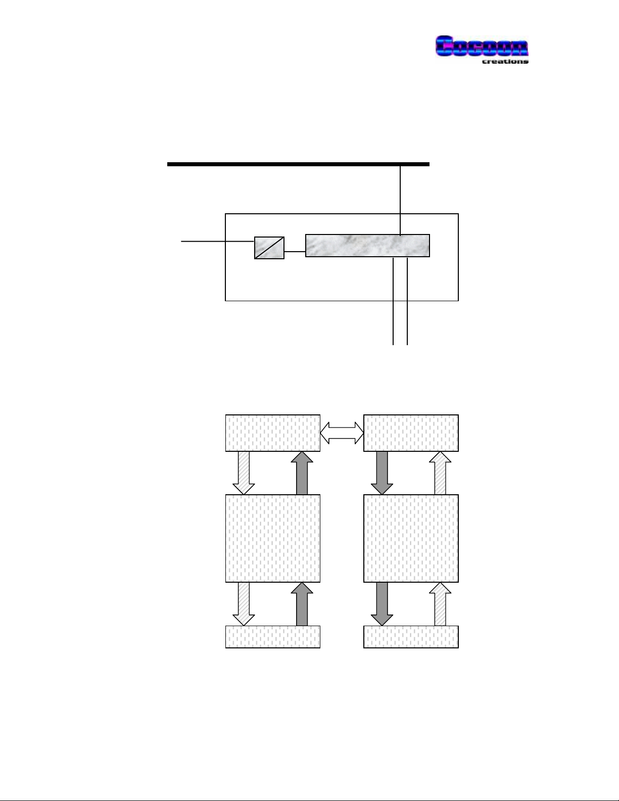
Schematic overview of PowerTALK 101
Ethernet LAN segment, TCP/IP, UDP, etc.
TCP/IP Ethernet port - to communications master
AC Power
Isolated PSU Communications
Processor
Non isolated RS-232 ports for connection to
communication equipment in the field
Serial ports: Serial 1 Serial 2
Encapsulated
Data, see p50
PT 101
Raw serial Data
Encapsulated
Data, see p50
PT 101
Raw serial Data
11
Page 13
PowerTALK 101
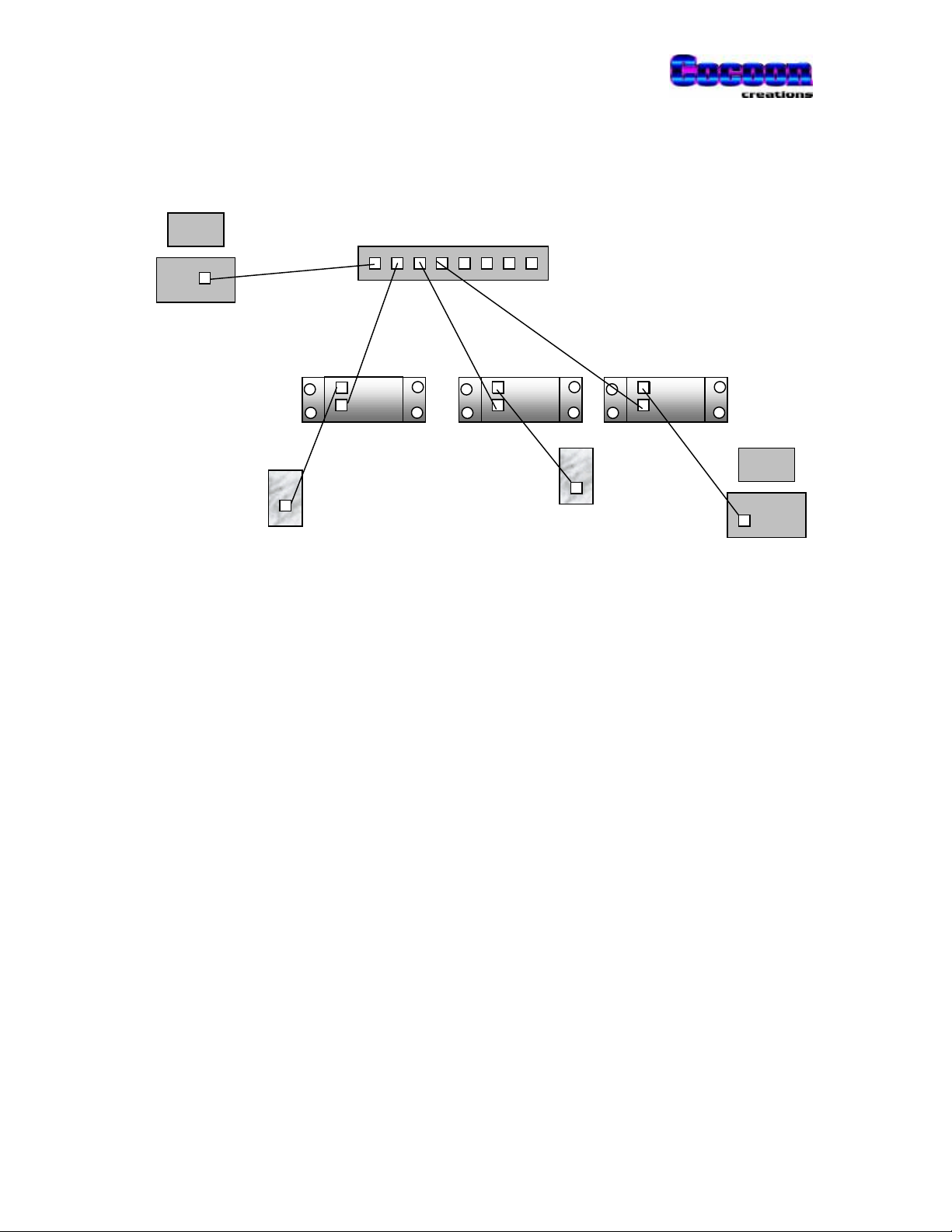
Network topology overview of PowerTALK 101
PC Hub (UTP/ Thinnet)
Configuration PC
On Ethernet
Ethernet
PowerTALK 101
RS-232 Serial devices
RS-232
Master PC
On COM port
12
Page 14
PowerTALK 101
Physical properties
PowerTALK 101 picture
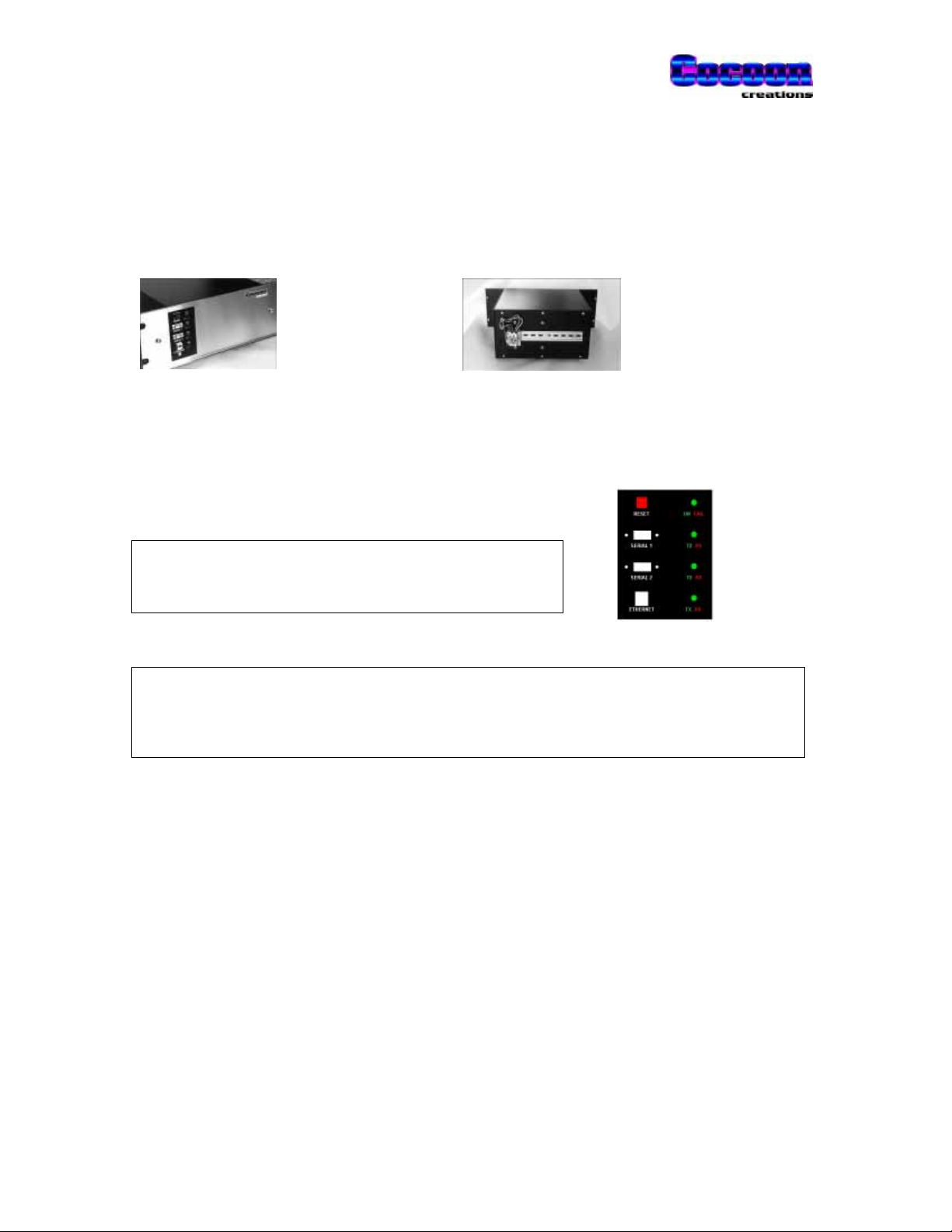
Front view Rear view
LED, plug and switch layout
Reset
Serial 1
Serial 2
Ethernet
Reset
Serial 1
Serial 2
Ethernet
Green:ON Red: PowerTALK Failed
Green: Transmit Red:Receive
Green: Transmit Red:Receive
Green: Transmit Red:Receive
Press to restart all on-board processors in case of suspected system
malfunction, or LED test
Serial Port 1: 1200 – 19200 bps, 5,6,7,8 bits, NOE parity, 1,2 stop bits DB-9
Serial Port 2: 1200 – 19200 bps, 5,6,7,8 bits, NOE parity, 1,2 stop bits DB-9
Ethernet medium – 10 Mbps 10-BASE-T RJ-45
13
Page 15
PowerTALK 101
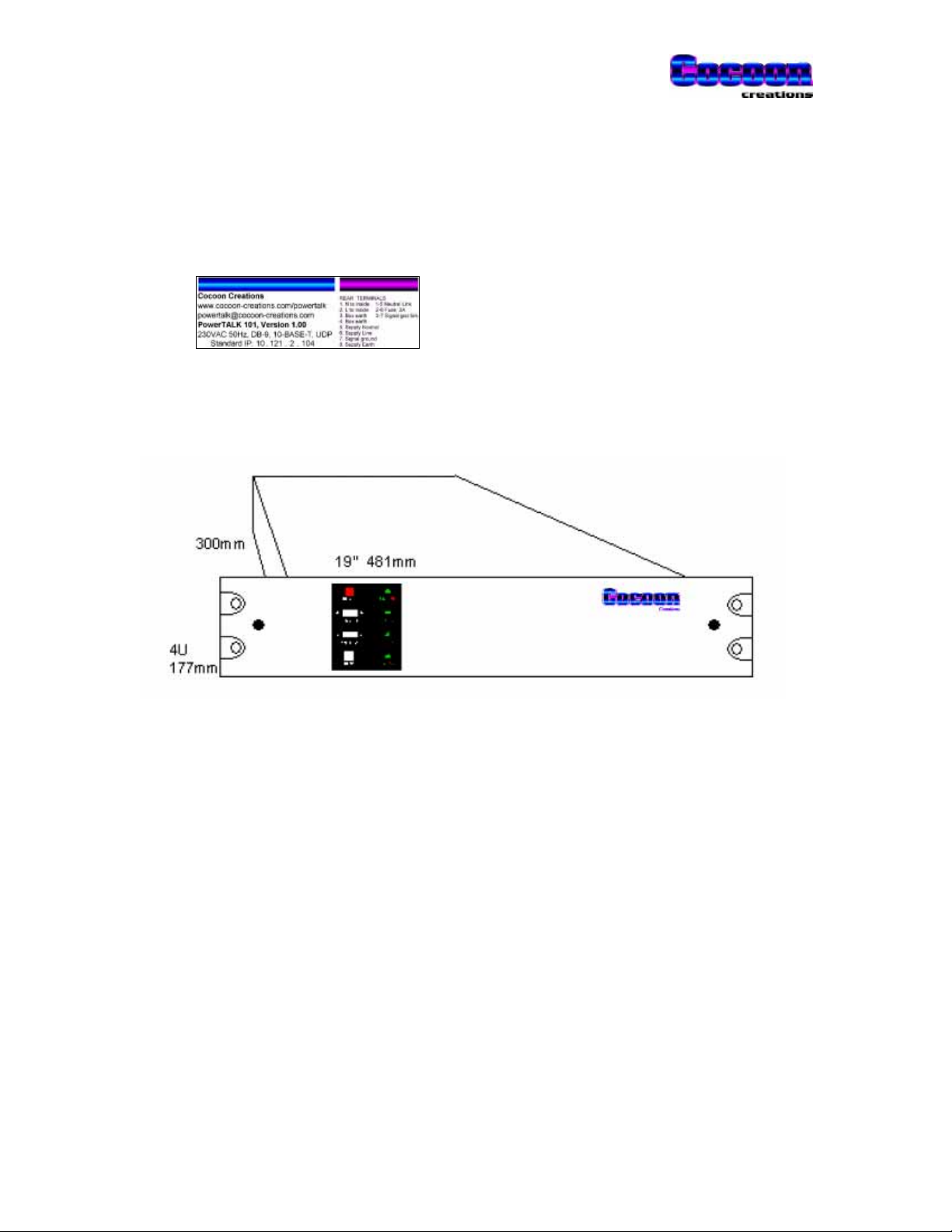
Device and terminal identification
Typical label for the 230VAC model, mounted on rear of PowerTALK 101:
Dimensions
PowerTALK 101 maximum dimensions.
Above dimensions exclude the terminal rail at the back of the PowerTALK 101 box.
Rear DIN rail
The 35mm DIN rail is provided for convenience, to mount up to two PowerTALK 103 RS-485
converters or other third party rail mount equipment such as power supplies, etc.
Additional power supply outputs
An additional power supply unit for external equipment with mounting holes 90mm x 90mm may
be mounted inside or outside the box, using the 4mm diameter holes provided. Such power
supply may be obtained from third parties, or from COCOON. See pages 8, 17 and 21.
Face plate care & maintenance
14
Page 16

PowerTALK 101
The front surface is of brushed stainless steel, and shows fingerprints easily on the textured
finish. To remove, use a cloth with alcohol or spirits. Take care not to allow the volatile fluid to
come into contact with the vinyl stickers on the surface of the front plate.
When wiping the front panel surface, wipe horizontally; in the same direction as the brush finish
texture for the best results.
Internal connections and layout
PowerTALK 101 seen from the front, with its faceplate removed
The main elements of PowerTALK 101 can be seen as follows:
A Communications processor 80486
B Power Supply 5V 4A isolated
CLEDplug DB-25
D Spare power supply mounting holes 90 x 90 mm
H Reset button Reset
I Spare communications processor card slot
for future expansion
80486 or Pentium
15
Page 17

PowerTALK 101
Fuses & links
• One PC board mounted 5mmx20mm fuse, 1A rating, fast blow
This fuse is for PSU overload protection
• Between terminals X1:2 and X1:6, a fuse with 3A rating, slow blow
This fuse is for short circuit protection against possible short circuit inside the box
• Between terminals X1:1 and X1:5, a link terminal
A link is used to isolate the Neutral or Negative power supply if needed.
• Between terminals X1:3 and X1:7, a link terminal
A link is used to connect the signal ground to the chassis ground.
Battery replacement
The PowerTALK 101 unit has a built in battery for the purpose of keeping time when the power
supply is removed. The lithium battery is expected to last for at least 10 years.
It is easily replaced by opening the front cover. The battery location is shown on page 17,
indicated as “BAT”.
16
Page 18

PowerTALK 101
Jumper settings
PowerTALK 101 contains two printed circuit boards:
Power supply board
No jumpers or options on board
A. One 2-pin, 0.3” spaced connector connected to power input
This connection is connected to terminals X1:1,5 and X1:2,6.
B. One 2-pin, 0.1” spaced connector with output 12VDC, 50mA
This supply is not needed by PowerTALK 101, but can be used by the user’s
equipment
C. One set of screw terminals for output 5VDC, 4A. N.B. Observe polarity:
The RED bootlace lug is +5V, whilst the BLUE bootlace terminal is 0V.
The communications common signal, 0V, can be switched to earth by
the disconnect terminal between X1:3 and X1:7
CB A
PowerTALK 101 230VAC power supply
17
Page 19

PowerTALK 101
ABD
G
Communications processor boa rd
Jumper settings are not user configurable, and are to be as per diagram below:
Connections
A. Port 1 to SERIAL 1 (green CAT-5 UTP cable) to front plate connector
B. Port 2 to SERIAL 2 (blue CAT-5 UTP cable) to front plate connector
C. RJ-45 to ETHERNET (yellow CAT-5 UTP cable) on front plate
D. 2-pin J3 to reset button on front plate
E. LED lead connector inside box
F. 4-pin 5VDC input power connector
Observe polarity according to board markings “+5V 0V”.
G. Lithium battery
E
Jumpers on Communications Processor
F
18
Page 20

PowerTALK 101
Electrical connection to PowerTALK
External Wiring
PowerTALK 101 only needs three power connections, i.e. earth, L and N. In the case of the DC
powered model, it is earth, V+ and V-.
NLEarth
230VAC Power Input
Earth Wiring
All metal panels in the PowerTALK 101 box are earthed to the star point at the back of the box.
The logical earth (low noise earth point) used by the internal PowerTALK 101 electronic cards,
can optionally be connected to the system earth. The blade disconnect terminal switch between
terminals X1:3 and X1:7 performs this function.
19
Page 21

PowerTALK 101
The blade disconnect earth link is shown below:
Clean earth connection can be connected to earth via link switch
.
Isolation in the PowerTALK 101 box
Below a schematic diagram of the electrical isolation barriers as implemented:
PowerTALK 101 box
20
Page 22

PowerTALK 101
PowerTALK 101 specifications
Main processor component
Advantech processor unit configured as protocol converter card.
Main power supply
The main power supply is designed to exceed the requirement of the load by at least 100%. This
ensures low operating temperatures through the entire temperature range and guarantees longer
equipment life.
Optional power supplies
PowerTALK 101 has one open power supply mounting position, in which a power supply for
external use could be mounted. 2.5kV isolated power supplies available are:
230VAC, 220VDC, 110VDC 2A 5V or 9V output
230VAC 4A 5V or 9V output
21
Page 23

PowerTALK 101
PowerTALK 101 specifications
Item PowerTALK 101 PowerTALK 101B
Serial ports 2x RS-232, DB-9 male Ditto
Serial port settings 1200-19200 bps, 5,6,7 or
8 bits, N/O/E parity, 1,2
stop bits
Serial port signals supported Tx, Rx
Handshake signals high
Maximum recommended 3 wire serial
port speed
Ethernet standard IEEE-802.3 CSMA/CD Ditto
Ethernet speed 10 MB/s Ditto
Ethernet medium 10 Base-T unless
IP address Unique fixed IP & user
Ethernet mode UDP broadcast only Ditto
19200 baud Ditto
otherwise specified
Optional 10 Base-2
Optional 10BASE-5 or
10BASE-FOIRL
definable IP
Ditto
Ditto
Also DTR and flow control
Ditto
Ditto
Also UDP peer to peer
Network traffic burden Depending on settings:
From 8kbps (3840
packets/s) to 1Mbps
(30packets/s) for a 19200
bps serial data flow
Supervision Watchdog timer checks for
continuous program
execution
Isolation: PSU Input voltage to earth 2.5 kV RMS Ditto
Isolation: PSU Output voltage to earth 2.5 kV RMS Ditto
Isolation: RS-232 to earth 2.5 kV RMS Ditto
Electrical terminals Phoenix Contact terminals
MTK-P/P, UK5-N, UK4-TG
Processor type Intel 486 Ditto
Processor memory type DRAM modules, FLASH
RAM chips
Processor mode Protected mode Ditto
Energy saving (radiated heat
reduction)
Processor normally used
or switched to standby
mode
Ditto
Ditto
Ditto
Ditto
Ditto
Configuration User set by PT.EXE, using Ditto
22
Page 24

PowerTALK 101
either a network
connected or serially
connected PC.
Configuration storage Non-volatile memory on
board
Firmware upgrade In Flash memory Ditto
Ditto
Power supply voltage 230VAC, unless otherwise
specified
Power supply current 0.2A typical at input of
230VAC
Power supply output 20W, regulated 5V
0.6W, unregulated 12V
Internal PSU fuse 1A 5mmx20mm fast blow Ditto
External fuse 3A 5mmx20mm slow blow Ditto
Enclosure All metal (steel) case, 19”,
4U, maximum depth of
340mm, including the
protruding terminals on the
back of the unit.
Material of top & bottom plates 1mm mild steel, powder
coated
Material of central part 2mm galvanised steel,
powder coated
Material of front plate 0.9mm brushed stainless
steel
Environmental 0 to 50 degrees C Ditto
Ditto
Ditto
Ditto
Ditto
Ditto
Ditto
Ditto
23
Page 25

PowerTALK 101
24
Page 26

PowerTALK 101
Connecting PowerTALK 101 to a network
Quick start guide
The following is a procedure to quickly get multiple PowerTALK 101 units running, and configured
for a test case:
Power Supply
Connect L to terminal X1:6, N to X1:5 and Earth to 8.
Open link between 7 and 3 (to isolate grounds)
Insert included fuse holder / key into terminals 2/6
Networking
PowerTALK 101 units are delivered with both port settings 9600 8N1, a fixed IP address as
marked on back of unit, channel 1 connected to Port 1 and channel 2 connected to Port 2. The
system is delivered, tested, set up with all serial ports 1 as logical links, and serial ports 2 also as
logical links.
1. Power up each unit and check that after a waiting period of approximately 30 to 45 seconds,
theLEDscyclethroughastart-uppatternandfinallystabilisethereafter.
1.1 Within 10 to 15 seconds after start-up or RESET, it should beep
1.2 After about 45 seconds after start-up or RESET, it should show the LED test pattern, and
beep.
1.3 After the second beep, the functionality of the PowerTALK 101 is set
2. Connect all the units (at least two) to a single network segment or hub.
3. Connect your master device (normally PC) to one port on channel 1 (e.g. Port 1 on
PowerTALK unit A) using a Laplink cable.
4. Connect your slave device (typically printer or modem) to the same port on another
PowerTALK 101.
Set the PowerTALK unit to match the printer or device baud rate, if the default setting does
not comply.
5. Send data, and check for successful operation.
25
Page 27

PowerTALK 101
Changing more advanced parameters using PT.EXE
1. Connect a PC serial port set for 9600 baud, 8, N, 1 (or actual port settings if changed from
default) to any PowerTALK port using a Laplink serial cable (Tx and Rx swapped).
2. Run either PT98 (PowerTALK 98 for Windows 95/NT GUI) or PT (PowerTALK for Windows
95/NT command line). Only PT will be covered here. PT98 is graphical, and perform similar
functions with the known Windows look and feel.
3. To get a list of PT’s capabilities, run “PT.EXE –h”. See printout below.
4. To display all units on line, PT.EXE can simply be run from a command line prompt. Notice
that the firmware version number is displayed for all the units. It is best if they are all the
same version - contact your distributor in case of query.
5. The unit can now be configured. The default configuration is 9600 8N1, Transmit delay is 0,
SERIAL 1 ports connected to channel 1 and all SERIAL 2 ports connected to channel 2. The
password is always ‘jovian’ if PowerTALK is accessed from the local serial port, and the
factory default password is ‘martian’ for access from the network port. PowerTALK 101 units
have standard IP addresses, printed on the sticker on the back of the unit. You may also
enter a custom IP address for the unit, an IP address for the default gateway, and the
network subnet mask. Enter IP numbers as follows: 158.152.46.132
6. To save any changes, “PT.EXE –I10.1.1.7 martian commit aa.bb.cc.dd”.
7. Make a link between any pair of units (101B only) or allocate units that are connected to the
same network segment to a channel, by programming the channel set-up using PT.EXE:
PT.EXE password broadcast port channel.
Remember to “commit” after changing any configuration.
8. An easily achievable first attempt is to link port 2 on the local unit to port 2 on another unit.
Make two wire links on the chosen remote units serial port 2 - DB9 pin 2 to 3 (data loop
back). You can then leave your PC/terminal connected to your local port 2 and then type
characters which should echo back onto your screen, having been looped back by the remote
unit.
9. Whenever you are configuring or linking to units on remote sub-nets, you must use IP
numbers, not names.
26
Page 28

PowerTALK 101
Passwords
Two different passwords are kept on the PowerTALK 101 units. One is variable and can be used
for access from a remote network location, and the other fixed but only for access from the local
serial port.
The password for network access can be changed, and can also be forgotten. The password for
local access using the local serial port is fixed, for the eventuality a user forgets his password.
The standard serial port (master) password is: ‘jovian’
The default network (changeable) password is: ‘martian’
27
Page 29

PowerTALK 101
PT.EXE – PowerTALK command line interface
The command line interface under W95 DOS or WNT command line, connects to PowerTALK
units via the TCP/IP Ethernet port and network.
Command line options for PT.EXE are given below:
PowerTALK 101 configuration utility version 1.01. Type pt -h for help.
Copyright 1998
For distribution with PowerTALK 101 by Cocoon Creations CC.
Usage:
PT [options]
PT [options] password command hst [arguments]
hst is the hostname or IP address.
Options:
-h Display help screen
-w Do not quit after OK or ERROR, wait for 1 second inactivity.
-i# Use Local IP number #, as detected above.
-In.n.n.n Use specified local IP number.
-Bn.n.n.n Use specified local broadcast, defaults according to IP class.
Commands:
hostip hst IP Set the user-definable IP address
hostname hst newname Specify a new hostname
netmask hst netmask Set the netmask address
gateway hst gateway Set the gateway address
broadcast hst prt chn Set the port to broadcast to a specific channel
disconnect hst prt Disconnect this port from the network
speed hst prt spd Set the port speed in bits per second.
parity hst prt prt 0/1/2 sets none/odd/even parity.
stopbits hst prt bits selects stopbits, 1 or 2.
databits hst prt bits set 8,7,6 or 5 data bits.
txdelay hst prt n Wait for n character periods before transmit.
password hst password Set the password.
commit hst Makes config changes effective.
rollback hst Cancels config changes.
config hst Report the current configuration.
reset hst Performs a hard reset.
If PT.EXE is able to detect the Windows NT IP address, it will display and use it automatically. It
can still be overridden by the –I command.
PT.EXE examples
Confirm your PC IP address
From a command prompt in Windows 95/98/NT, type:
IPCONFIG (inthecaseyouarerunningNT),or
WINIPCFG (in the case you are running W95/98)
The PC will respond with it’s IP address(es), in this example this will be assumed to be 10.1.1.7.
Confirm that the IP address(es) thus obtained corresponds with the values as set on page 35
(Network connection: IP address setting).
28
Page 30

PowerTALK 101
List all available PowerTALK units
From a command prompt in Windows 95/98/NT, type:
PT –I10.1.1.7
A list will be displayed with the connected PowerTALK units, for this example 10.121.3.85 is the
PowerTALK 101 unit assumed to be connected.
Set a PowerTALK unit name
From a command prompt in Windows 95/98/NT, type:
PT –I10.1.1.7 martian hostname 10.121.3.85 OUTSTN1
where “martian” is the default network password,
where “hostname” is the item to change command and
where “OUTSTN1” is the new unit name.
Change some parameters
From a command prompt in Windows 95/98/NT, type:
PT –I10.1.1.7 martian speed OUTSTN1 2 4800
where “2” is the port number on OUTSTN1
Change a port/channel allocation
From a command prompt in Windows 95/98/NT, type:
PT –I10.1.1.7 martian broadcast OUTSTN1 2 34
where “34” is the new channel number of port number “2” on OUTSTN1
Accept all changes
From a command prompt in Windows 95/98/NT, type:
PT –I10.1.1.7 martian commit OUTSTN1
to store changes into non-volatile memory
29
Page 31

PowerTALK 101
PowerTALK 98 – Windows GUI software
PowerTALK 98 is the 32 bit Windows interface to PowerTALK 101. The Windows software
connects to a serial port on PowerTALK 101.
PowerTALK 98 is developed to simplify the process of setting up a number of PowerTALK 101
units locally or from remote. PowerTALK 98 requires one serial connection from a PC running
Windows 95, 98 or NT to a PowerTALK 101 unit. Over such serial link, all PowerTALKs including
the Ethernet connected ones can be configured, and re-configured.
Upon start-up PowerTALK 98 needs to establish serial communication with any PowerTALK 101
unit. The first screen asks for the serial port details previously set up on the PowerTALK 101
units. Factory defaults on PowerTALK 101 units are 9600 baud, 8 bits, no parity, 1 stop bit.
First PowerTALK 98 setup screen
The
Default Password
state, i.e. the default password enables changing of any networked PowerTALK 101 unit. Should
the user want to password protect the system, the passwords on each PowerTALK 101 unit may
be changed, and the default password on the screen below may also be changed.
Once communication to the serially connected PowerTALK 101 unit is achieved, all networked
PowerTALK 101 units will be listed. Any PowerTALK units located across a network bridge or
router (101B or 101C models) will not be seen by this list until their IP addresses are manually set
up in PowerTALK 98.
on PowerTALK 98 is set as “martian”. The system is delivered in the open
All connected PowerTALK 101 units listed
30
Page 32

PowerTALK 101
PowerTALK 98 examples
Double clicking on a selected PowerTALK 101 unit on the main screen results in either of the
following screens to pop up. These screens may be used to set up both network and serial port
parameters.
Note the password must be set correctly for any change to take effect:
Change TCP/IP network configuration Change serial port details
• A
Password
the password previously set on the PT unit
• A
New Password
• An arbitrary
to a unit
• A second
Gateway
user network
needs to be set according to
on the unit may be set
Host Name
may be assigned
IP address,Netmask
may be configured as used in the
A connected unit and port may be selected
Serial Port Settings
length, etc. may be changed
The port may be assigned to a
number
The unit’s
&
TCP/IP packet will be transmitted after a delay
time equivalent to the max. transmission time
of the specified number of bytes (at 10 bits per
byte at the current baud rate).
, see p47 for details
Buffer Settings
such as baud rate, word
may be changed. A
channel
31
Page 33

PowerTALK 101
Network Topology
PowerTALK 101 allows your Ethernet system to be used for control data transport tasks without
interfering with normal network operations. The units are 802.3 compliant and use protocols from
the TCP/IP suite, so they are fully routable and because they only use Ethernet capacity when
carrying data – they have very little affect on network performance.
WAN
LAN segment LAN segment
Other PowerTALK PowerTALK Other PowerTALK
network A B network ‘N’
equipment equipment
data in/out data in/out data in/out
Each unit has two RS232C ports and a network port. Normally DB-9 connectors and 10-BASE-T
are assumed, but DB-25, 10-BASE-2 and 10-BASE-5 is also available. You may connect as
many units as you wish to the network and establish logical connections between units with
complete flexibility. For example, imagine two units each connected to a network, but at some
distance from each other. The two ports could be set up as shown below so that they all carry
data simultaneously -
DD RS232 RS232 DD
EE RS232 RS232 EE
PowerTALK PowerTALK
AB
2 logical circuits carried by Ethernet LAN.
32
Page 34

PowerTALK 101
PowerTALK 101 allows its two ports to be individually linked to any port of any other PowerTALK
101 unit (the above example shows them linked in a one-to-one fashion just for simplicity). You
can connect as many PowerTALK units as you wish to your network, obeying normal Ethernet
rules, and set up connections between units with complete freedom. For example, set one unit to
accept data from several other units -
PowerTALK
master
PowerTALK PowerTALK PowerTALK
128
8 logical circuits carried by
Ethernet LAN.
data in/out data in/out data in/out
These and many other configurations can be easily set up, monitored and changed at will from
any unit on the network serially connected to a PC. PT.EXE allows you to make and break logical
links between units, examine and change configurations, unit names, IP numbers etc. of any
PowerTALK 101 on the network. Security is provided by a password for every unit.
PowerTALK 101C provides error corrected, self-repairing logical links. Every network packet is
error checked and sequence numbered to ensure all your data is delivered and is error free.
Should the network or the power fail, all PowerTALK models will automatically re-link when the
problem is resolved.
33
Page 35

PowerTALK 101
PowerTALK 101 configuration
Pre-connect configuration
You can make a few minor configuration changes to each unit before you connect them to your
network. The most important thing is to give each unit a unique name and or IP number. Each
unit has storage for all user configurations and these configurations are reloaded each time the
unit is powered up.
PowerTALK 101 can be connected to the network in its default configuration. The default name
and IP number parameters are based on the unique MAC address of the PowerTALK unit.
Typical default IP address 10.121.1.147
Typical constant part of IP address 10.121.xx.yy
Typical custom IP address 100.100.100.3
PowerTALK 101 is configured by PT.EXE or PT98.EXE. Both packages can use either the
network port or a serial port for configuration.
Serial connection cables
In the case of serial configuration, a Laplink (swapped over) cable is required for communication
between the PC and PowerTALK 101. The serial ports are configured as DTE so a Laplink PC
serial cable can be used with crossovers.
34
Page 36

PowerTALK 101
Network connection: IP address setting
In the case of network configuration, the host PC must be configured to be able to speak to the
network ports on the PowerTALK 101s. Using Windows NT, one must “add” another IP address
to its configuration. Using Windows 95, only one IP address is allowed per PC, forcing the user to
change his network settings each time he changes networks form the normal office network to the
PowerTALK Ethernet network.
Below, the screens used for changing the IP addresses correctly are shown. Should no
networking be set up on your machine, contact your network administrator to set your Windows
machine up for networking.
The IP address shown on the screen prints below is used throughout this document, and can also
be used on your Windows machine, provided the example IP address 10.1.1.7 does not exist
already.
Windows NT Windows 95
• Click Start/Settings/Control Panel
• Click Network/Protocols
• Select TCP/IP
• Click Properties, Advanced
• Add an IP address like 10.1.1.7 to match
the PowerTALK 101 default IP address
range 10.x.x.x.
• Click Start/Settings/Control Panel
• Click Network
• Select TCP/IP
• Click Properties
• Change your IP address to something like
10.1.1.7 to match the PowerTALK 101
default IP address range 10.x.x.x.
Multiple IP addresses allowed Only one IP address is allowed
IP configuration of the TCP/IP protocol in the W indows 95 and NT operating systems
35
Page 37

PowerTALK 101
Other settings on PowerTALK 101
Next, using PT.EXE or PT98.EXE, rename each PowerTALK 101 unit to suit your site. You may
also change passwords, port settings, IP number, default gateway IP number and subnet mask
from this menu. Note that a subnet mask must be defined if the custom IP address is used.
Connecting to the physical network
The relevant medium must be connected, i.e. a RJ-45 telephone connector in the case of 10Base-T.
10-BASE-T
PowerTALK 101 can be connected with a normal UTP CAT-5 flylead to a network hub.
PowerTALK 101 can be connected to another PowerTALK 101 unit with a special UTP CAT-5
server cable (crossed Tx and Rx cables).
36
Page 38

PowerTALK 101
Commissioning aids
LED indications
Normal LED indications on face plate:
Refer to the LED description on page 13.
All LEDs are scanned through all possible states in sequence
immediately prior to start of operation.
• ON/FAIL
Green
Red
• Serial 1 Tx/Rx
Green
Red
• Serial 2 Tx/Rx
Green
Red
• Ethernet Tx/Rx
Green
Red
The communications processor card has initialised and is working properly
An operational error has occurred.
This
Red
is not automatically recovered. The machine must be reset.
Transmits serial data
Receives serial data
Transmits serial data
Receives serial data
Transmits packet
Receives packet destined for local IP address
red/green
, top to bottom,
Indications on inside of box, only visible when cover is removed:
• Power
Red
• Ethernet
Green
Flashing Red
Red
Communications processor board powered up, +5VDC.
Indicates a physical link has been established
Indicates network traffic
Ethernet ready / power
37
Page 39

PowerTALK 101
Tests
Tests using standard networking protocols:
• The standard PING program supplied with Windows 95/98/NT can be used to determine
network operation, confirming PING time to the specified PowerTALK unit.
Tests available using PT.EXE
• Networking loopback echo test. A special packet is sent to PowerTALK 101, and a special
packet containing address information is returned.
Tests available using PowerTALK 98 under Windows 95 or NT
• Networking loopback echo test. A special packet is sent to PowerTALK 101, and a special
packet is returned. The total loop time is measured. This packet returns address information
to PowerTALK 98.
• Loopback echo test. A loopback connector must be installed on the PowerTALK 101 serial
port. The total loop time for a single character transmitted through the loopback connector is
measured.
38
Page 40

PowerTALK 101
Testing procedure
It is suggested that a PowerTALK unit or system is laboratory tested prior to shipping to site.
A simple, but effective test is described below:
Using the default settings on the PowerTALK unit, i.e.: 9600 8N1, with the standard IP addresses,
as are indicated on the back of the units.
1. Power up 2 PowerTALK units,
confirming that the green “ON” LEDs
are on
2. Connect a Server Flylead (Crossed
over UTP lead) between the two
PowerTALK units
3. Connect a loopback connector to port 1
or 2 on a PowerTALK 101 unit
4. Connect a Laplink cable between the
other PowerTALK unit, and the PC
COM2.
5. Run HyperTerminal on Windows 95/NT
6. Set HyperTerminal to COMn where
COMn is your available COM port
7. Set HyperTerminal to the settings
shownontheright
8. Ensure “local echo” is off on
HyperTerminal
9. Type into the terminal emulation
program, and you should see an echo
returning on the screen. This comes
from the loopback plug, and will stop if
the loopback plug is removed.
10. The LED indications can also carefully
be checked, observing the flow of data.
39
Page 41

PowerTALK 101
Easy functionality test - Loopback test:
A terminal program is used to send a character through a set of PowerTALK units, through the
loopback connector, and then echoed back to the terminal program. The complete loop is
functional if the echo is visible.
“A”
input
“A”
echo
Serial 1 PowerTALK 101 A
“
” “
“
” “
”
”
Ethernet
Channel 1 PowerTALK 101 B Serial 1
“A”
loopback
Schematic loopback test
• A character is sent from HyperTerminal on the PC COM port into the Serial 1 port on
PowerTALK 101 “A”
• The character is packetised and sent from PowerTALK 101 “A” to “B” over Ethernet, on
channel 1 (Serial 1 is configured onto channel 1)
• PowerTALK 101 “B” receives a packet on channel 1, destined for Serial 1 (Serial 1 is
configured onto channel 1)
• PowerTALK 101 “B” strips the packet, and outputs the character to its Serial 1 port.
• PowerTALK 101 “B” Serial port 1 has a loopback connector, and the bits are bounced back
into Serial 1.
• The character is once again packetised and sent from PowerTALK 101 “B” to “A” over
Ethernet, on channel 1 (Serial 1 is configured onto channel 1)
• PowerTALK 101 “A” receives a packet on channel 1, thus destined for Serial 1 (Serial 1 is
configured onto channel 1)
• PowerTALK 101 “A” strips the packet, and outputs the character to its Serial 1 port,
connected to the PC COM port.
• This character will then be displayed as an echo on the HyperTerminal screen.
• Removing the loopback plug, or inserting it into the incorrect channel/port will stop the echo
from occurring.
40
Page 42

PowerTALK 101
Port 1 = Ch 1
Port 2 = Ch 2
B
Insert Loopback
plug into Serial
1
Default settings:
9600 8N1
COM1
Use Windows’
HyperTerminal,
connected with
a Laplink cable
Port 1 = Ch 1
Port 2 = Ch 2
A
Usetheredserverflyleadto
connect Ethernet ports
Loopback test connection
For the loopback test described above, no setting changes are required. The PowerTALK 101
units can be unpacked from the original boxes, powered up, and immediately be connected to
perform above functionality test. The same test can also be executed using arbitrary settings as
can be changed using PT.EXE.
41
Page 43

PowerTALK 101
Setting and configuring PowerTALK 101
Default settings:
9600 8N1
Use Windows’
HyperTerminal,
connected with
a Laplink cable
Port 1 = Ch 1
Port 2 = Ch 2
A
Usetheredserverflyleadto
connect Ethernet ports
Port 1 = Ch 1
Port 2 = Ch 2
B
Setting and configuration
Any PowerTALK 101 unit can be remotely configured from any connected PowerTALK 101 serial
port or Ethernet port. In above example, “A” is connected using a serial connection, and “B” is
connected using its network port. In both cases PT.EXE can be used to configure the PowerTALK
101 unit.
For configuration detail, see the section on PT.EXE parameters.
42
Page 44

PowerTALK 101
Practical connection example – Address type serial devices
An address
the master station. The device is given some ID address to which it will respond.
The connection below effectively connects device C and D to the same multi-drop network.
This connection demands a device that will only respond to its ID call from a master controller.
All ports set to
channel 1
type serial device
COM1
10-BASE-2
Backbone
Use Windows OEM
software, connected
with a Laplink
cable to
PowerTALK 101
uses a protocol preventing it from answering to all messages from
Port 1 = Ch 1
Port 2 = Ch 1
A
Use standard flyleads to hub Connect Serial 1
Port 1 = Ch 1
Port 2 = Ch 1
B
&2toserial
devices using
original PC-todevice cables
Practical connection example
Circles indicate different locations
43
Page 45

PowerTALK 101
Practical connection example – Non address (old) type serial devices
An address or
from the master station. The device is given some ID address to which it will respond. A nonaddress or non-ID type device will respond to all message on the serial line, assuming everything
is destined for it.
The connection below effectively splits COM1 and COM2 on the PC, ensuring individual logical
connections (channels) from COM1 and COM2 to the devices C and D.
A serial stream from COM1 (Serial 1) will only go C, and COM2 (Serial 2) will only go to D.
All ports set to
channel 1
ID type serial device
COM1, 2
10-BASE-2
Backbone
Use Windows OEM
software, connected
with a Laplink
cable to
PowerTALK 101
uses a protocol preventing it from answering to all messages
Port 1 = Ch 1
Port 2 = Ch 2
A
Use standard flyleads to hub Connect Serial 1
Port 1 = Ch 1
Port 2 = Ch 2
B
C
D
&2toserial
devices using
original PC-todevice cables
44
Practical connection example
Circles indicate different locations
Page 46

PowerTALK 101
Practical multi node example
This example assumes two different types of protocols, not allowed to be on the same physical
serial network. It shows each PC COM port to go to a different subnet of address or ID type serial
devices, i.e. devices each with an individual address on the subnet.
The equivalent logical network is also shown below:
All PowerTALK
101s set to:
A
9600 8E2 or
as required by
application
COM1, 2
COM1
COM2
Ethernet
PC Connections:
COM1 to Serial1 (Ch. 1)
COM2 to Serial2 (Ch. 2)
Settings A,B,C:
Ch. 1 to Serial1 (used by device type ABC)
Ch. 2 to Serial2 (used by device type XYZ)
Settings D:
Ch. 1 to Serial 1&2 (used by device type ABC)
Ethernet
Backbone
RS-485 sub
network
Practical multi node connection
Circles indicate different locations
B
C
D
45
Page 47

PowerTALK 101
To the PC master station it appears to be connected to two separate transparent serial links.
COM1
COM2
Equivalent virtual network as seen by the PC
46
Page 48

PowerTALK 101
Technical detail
Settings for popular Siemens & GE Multilin equipment
The serial settings for Siemens DIGSI 7SJ600 protection relays are: 11 bit, 9600 8E1
The serial settings for GE Multilin 239 protection relays are: 10 bit, 9600 8N1
Channels
The concept of channels was introduced to facilitate the selective connection of various
PowerTALK units, connected to the same Ethernet network.
A channel has all the necessary intelligence to facilitate full duplex connections between any of its
members. Important to note, that all ports will reflect all data flowing in all directions. To make
such a connection useful, the user’s protocol must accommodate multi-drop connections.
• Each serial port on each PowerTALK unit is connected to a specified channel.
• All incoming serial data will be made visible on the specified channel, on Ethernet.
• All PowerTALK units will listen for packets on the Ethernet, bearing the specified channel
• If a PowerTALK unit sees a packet destined for any of its serial ports, the packet gets
disassembled, and the serial data contained within is output into the relevant port
All PowerTALK 101 units are factory set as follows: all Ports 1 on all PowerTALK units are
connected to channel 1, and also all ports 2 onto channel 2. All connections are one-to-many, i.e.
a multi drop arrangement.
Channel 1 Channel 2 Channel 3 Channel 4
PowerTALK “A”
PowerTALK “B”
PowerTALK “C”
PowerTALK “D”
For one-to-one connections, i.e. classical RS-232 usage, a channel may only have 2 ports
defined. In the table below, 4 channels are defined for four logical links between four PowerTALK
101 units.
PowerTALK “A”
PowerTALK “B”
PowerTALK “C”
PowerTALK “D”
Serial 1 Serial 2
Serial 1 Serial 2
Serial 1 Serial 2
Serial 1 Serial 2
Channel 1 Channel 2 Channel 3 Channel 4
Serial 1 Serial 2
Serial 1 Serial 2
Serial 1 Serial 2
Serial 1 Serial 2
47
Page 49

PowerTALK 101
Potential PowerTALK lock-ups
Endless loop
If PowerTALK 101 SERIAL 1 is looped back to SERIAL 2, and both ports are configured on the
same channel, an endless loop may occur as follows:
♦ Another PowerTALK 101 on the network on channel n, broadcasts a character
♦ The local PowerTALK 101 receives it
♦ Channel n receives it from Ethernet
♦ It gets delivered to serial port S1, which is connected to channel n
• It gets looped back to serial port S2 via the Laplink cable
• Serial port S2 is connected to and broadcasts it to channel n on Ethernet
• It is received by channel n on Ethernet (on the same machine!)
• It is re-delivered to serial port S1, still connected to channel n
• Ad infinitum
The best way to break out of this endless loop is to remove the loopback cable (Laplink cable)
from S1 to S2.
Loss of communication to configure PowerTALK 101
If the serial ports are (accidentally) configured to unknown settings, one may not be able to reestablish configuration with PowerTALK 101 via the serial port, i.e. if you’ve set it to 6 bits, 1200
baud, even parity, and you don’t know the port details, you wouldn’t be able to communicate.
In this case one can still access the device via the network port of a PC. If this is not available, or
the network password is forgotten, a system all reset is the only way to re-establish
communications.
For this special circumstance, a “back door” is left, and can be accessed as follows. Open the
front door of PowerTALK 101; remove the LED chord with the DB-25 connector. Insert a DB-25
male plug with pins 10 and 22 bridged. This will set the PowerTALK back to default serial settings
of 9600 baud, 8N1.
Link for reset to defaults
LED connector, DB-25F (holes) seen from the outside of the box.
48
Page 50

PowerTALK 101
Testing system watchdog
PowerTALK 101 has a watchdog system implemented to guard against hardware and/or firmware
failure. It is very difficult to test since one needs an actual faulty processor, but can be simulated
by the short, as indicated. The short actually forces the PowerTALK 101 unit to not refresh the
watchdog timer, resulting in repeated system reset.
Link for Watchdog test
LED connector, DB-25F (holes) seen from the outside of the box.
Using PowerTALK 101 with bridges and routers
Different versions of PowerTALK 101 behave differently with routers. PowerTALK 101
implements a broadcast protocol, meant for single or single virtual network segments, while
PowerTALK 101B implements the same protocol with point to point links. PowerTALK 101C
implements the TCP/IP protocol.
Ethernet bridges learn where the various MAC addresses on your network are and forward
packets accordingly. They will normally forward all PowerTALK 101 packets perfectly, but some
bridges allow filtering of packets based on certain criteria, for example broadcasts can be
discarded. If broadcasts are disabled, the PowerTALK 101 network will not see units on the far
side of the bridge. The same applies to routers and intelligent hubs. They will rarely pass
broadcasts, so units on the far side of them will not be seen. PowerTALK 101B will be able to use
any TCP/IP compliant bridge/router or intelligent hub. The PowerTALK protocol is fully TCP/IP
compliant, and allows any unit on the WAN to be -
1. Linked to any other unit.
2. Have its configuration examined and modified
However, units on different sub-nets of a WAN must be referred to by IP number not name, and
valid entries for IP number, default gateway IP number and sub-net mask must be entered into all
units. Refer to your network administrator.
49
Page 51

PowerTALK 101
PowerTALK 101 protocol
PowerTALK 101 supports the TCP/IP suit of protocols, namely IP, ARP, ICMP and UDP.
Presently it will respond to ICMP Ping and ARP, although it cannot originate Ping requests. ARP
requests are sent. PowerTALK’s own protocol and the transported data are carried inside UDP
datagrams. The data carried is 1 byte minimum (after time out) and128 bytes maximum. The
Ethernet encapsulation is as defined in RFC 894 and mandated by RFC 1022. The packet format
is shown below -
Mac Header -
6 bytes Destination MAC address
6 bytes Source MAC address
2 bytes Type - 0800 for IP packets, 0805 for ARP requests and 0806 for ARP replies.
IP header -
2 bytes IP Version - 4, header length - 20, TOS - 16 (4510h)
2 bytes IP packet length including header
2 bytes identifier (packet number, unique over a short period)
2 bytes fragmentation - 00
2 bytes TTL - 64, protocol - 17 = UDP (4011h)
2 bytes header checksum
4 bytes Source IP number
4 bytes Destination IP number
UDP header -
2 bytes Source port – variable
2 bytes Destination port – 7000dec
2 bytes length of UDP portion including header
2 bytes optional UDP checksum - set to 00
PowerTALK data -
2 bytes command_code // Command code
2 bytes target_comport // Target com port, 1=COM1 etc, -1=broadcast
2 bytes data_length // Length of data in data block
2 bytes source_comport // Source com port of data, 1=COM1 etc
2 bytes sequence // Incrementing sequence nr
2 bytes channel // Channel ID (for broadcasts)
20 bytes reserved // reserved (must be all 0)
128 bytes data // data buffer
50
Page 52

PowerTALK 101
Other products available in the PowerTALK family
PowerTALK 110
Serial data switch
Access & configuration from serial port(s), network port
REMOTE COMMUNICATION TO MULTIPLE RS-232 LINKS
6, 10, 14, 18 or 22 serial ports. More optionally available.
PACKETIZING OF SERIAL DATA STREAM ONTO ETHERNET
TCP/IP compatible
2.5kV isolation
PowerTALK 120
IP and/or MAC router
Access & configuration from serial port, network port
2, 3 or 4 network segments available.
TCP/IP compatible
2.5kV isolation
PowerTALK 100B
7SS50 V4.xx Event logger
Printing hard copies of important events
ON BOARD IMPACT PRINTER
Constant polling of 7SS50
Fault / trip recognition and automatic report printing
2.5kV isolation
PowerTALK 103
Isolated dual RS-232 to RS-485 converter
For industrial communication networks
CAPABLEOF CONNECTING 64 SIMILAR UNITS ON RS-485
Two master/slave modes
Optimal timing for 9600 or 1200 baud
19200 baud can be used, depending on software
Fits onto face of Siemens protection relay series
Tested with GE Multilin series and Siemens series protection relays
Port powered
DIN / G rail mountable
2.5kV isolation
Option: Remote software gate switching
No picture available
51
Page 53

PowerTALK 101
History of changes to this manual, from release 1
Release 2
Small changes are not listed.
Added “commit” under PT.EXE examples
Added section on PowerTALK 98
Clarified some of the sketches
Added section on battery replacement
52
Page 54

Notes
PowerTALK 101
53
Page 55

PowerTALK 101
54
 Loading...