

Page 1
COCOON
Essential
care
before,
during
and
after
TM
surgery.
Convective
Warming
Machine
PS
CE
Model
SERVICE
Distributed
CARE
Unit
Me
Email
Web
by
ESSENTIALS
62,
170
Waverley
queries@careessentials
www.careessentials
Forster
Vic
3149
CWS
PTY
LTD
Road
Australia
com.au
comau
4000
MANUAL
National
Phone
Fax
03
03
9562
9562
7713
7714
International
Phone
Fax
+61 3 9562
+61 3 9562
7713
7714
Designed
manufactured
in
Copyright © 2003
&
Australia.
Care
Essentials
Pty
Lid
Page 2
CONTENTS
IN
2.
OPERATION.
21.
2.2、
2.3.
24
3.
SAFETY
A
3.2.
3.3.
34.
4.
PREVENTATIVE
4.2.
4.3.
4.4.
4.5.
O
UnitSetup..........
Getting
Unit
Symbols
O
Stared
Operation
нина
νν
νο ντ
Procedure
νο
νο νε
нина
ντε τ εεττ ο ο
εκτ
κκωκκκεν
εεττ
τετ
κκκωννωνν
εεττ
τετ
nm
00000
ετεκ
eee
PRÉCAUTIONS
Warmnnd
Caution.................................................
Electromagnetic
Interference..........................
MAINTENANCE
O
Electrical
Performance
Temperature
Filter
Replacement
Safety
Inspection
Limit
Inspection
Thermostat
eee
Test
eee
Procedure
111
en
eee
ee
nene
ee K K K K
…............................................
eee
nenene
AA K KA
iii
κκ
κκν
τε
κε
eneret
nenene
iii
KA P P
111111
ーー
εεττ ετεκ
κε
κας
esserne
nene
ON
KKK
κκεεεεκκκας
8.
ener
nenene
nene
nné
eee
ekk k 8
ининининнни
10
лиинннни
12
2
4
4
5
5
6
7
7
7
7
7
8
8
9
5.
TROUBLESHOOTING…
5.1.
5.2.
53.
6.
6.1.
6.2.
6.3...
7.
7.1.
7.2.
8.
8.1.
8.2.
8.3.
Warming
Standby
EguipmentRepairs..............................................
SCHEMATIC
Control
Sensor
System
BOARD
Control
Sensor
SCHEMATIC
Control
Sensor
System
INC
9.1.
General
Blanket
Indicator
DIAGRAM
Boargd
Board
Block
COMPONENT
Board...
Board
DIAGRAMS
Board
Board
Block
li
Assembly
せ
Will
Not
Will
Not
DESCRIPTION
Diagram.................
LEGENDS
Schematic
Schenmatic
Diagram
Inflate
Light
νε
.Nt
Diagram
Diagram
irei
нии
ινε
εντ
ετων
ωνκκεε
εεττ
λε
εντ
τε
κε
ενεωκκκεεκκεεεεεε
… せ
… せ … せ
....................
ーー
トーーーーーーーーーーーーー
nm...
нии
m.
KG
e
eee
ee
R
RKK
εεττ
εκ
Rana
eee
eh
κτ
εεττ
ετεκ
ини
KE
KAP
ae
κκκκκ
κε ε τε
nn
hh
hn
ue
i
reeeen
κκ
κος
nn nn
εκ
κκαν
nn
nn
13
13
13
13
13
14
15
15
16
16
17
18
18
19
20
21
21
9.2.
9.3.
10.
11.
12.
Control
Sensor
WARRANTY
Board...
Board...........................
EEE
EEE
ee
KEE
HHK
H K
KKK
SPECIFICATIONS............................................
APPROVALS
KEE
nr
ero
rcncnncoinnnnos
нии
22
23
23
24
25
Page 3
Care
Essentials
CWS4000
Cocoon
Warming
System
Service
Manual
1.
It
information
Manual
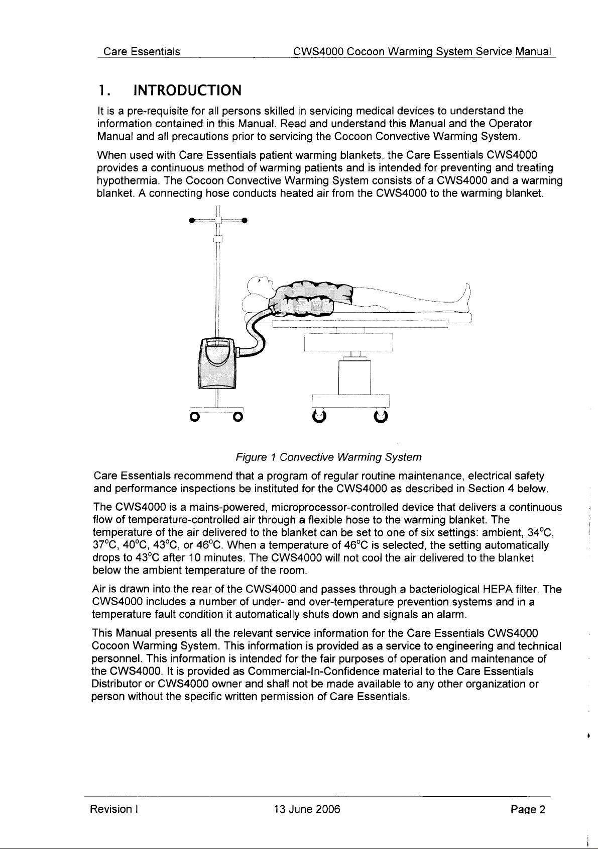
When
provides a continuous
hypothermia.
blanket. A connecting
INTRODUCTION
is a pre-requisite
contained
and
all
precautions
used
with
Care
The
Cocoon
for
all
persons
in
this
Manual.
prior
Essentials
method
hose
of
Convective
conducts
skilled
Read
to
servicing
patient
warming
Warming
heated
in
servicing
and
understand
the
warming
patients
air
from
medical
Cocoon
blankets,
and
is
System
consists
the
devices
this
Manual
Convective
the
Care
intended
of a CWS4000
CWS4000
to
understand
and
Warming
Essentials
for
preventing
to
the
warming
the
the
Operator
System.
CWS4000
and
and a warming
blanket.
treating
Care
Essentials
and
performance
The
CWS4000
flow
of
temperature-controlled
temperature
37°C,
drops
below
Air
CWS4000
is
drawn
40°C,
to
43°C
the
ambient
includes a number
temperature
This
Manual
Cocoon
personnel.
the
Distributor
person
Warming
This
CWS4000.
or
without
recommend
inspections
is a mains-powered,
of
the
air
delivered
43°C,
into
or
after
10
temperature
the
fault
condition
presents
System.
information
It
is
provided
CWS4000
the
specific
46°C.
minutes.
rear
of
all
the
owner
Figure 1 Convective
that a program
be
instituted
microprocessor-controlled
air
through a flexible
to
the
of
for
blanket
the
When a temperature
The
CWS4000
of
the
room.
the
CWS4000
of
under-
it
automatically
relevant
This
information
is
intended
as
Commercial-In-Confidence
and
shall not
written
permission
and
and
shuts
service
is
for
the
over-temperature
information
provided
be
of
Warming
regular
CWS4000
hose
can
be
of
46°C
will
not
passes
down
fair
purposes
made
Care
System
routine
set
cool
through a bacteriological
and
as a service
available
Essentials.
maintenance,
as
described
device
to
the
warming
to
one
is
selected,
the
air
prevention
signals
for
the
Care
of
operation
material
to
that
of
six
settings:
the
delivered
an
alarm.
Essentials
to
engineering
to
the
any
other
electrical
in
Section 4 below.
delivers a continuous
blanket.
setting
to
systems
and
maintenance
Care
organization
safety
The
ambient,
34°C,
automatically
the
blanket
HEPA
Essentials
filter.
and
in
CWS4000
and
technical
The
a
of
or
Revision
|
13
June
2006
Page
2
Page 4
Care
Essentials
CWS4000
Cocoon
Warming
System
Service
Manual
While
responsibility
product
without
If
or
details
you,
this
every
attempt
is
improvement
notice.
as a user
Manual,
are
located
has
taken
for
and
of
this
your
communication
on
the
been
made
any
errors
product
manual,
first
page
to
ensure
or
omissions.
specifications
have
any
relevant
with
Care
of
this
Manual.
this
Manual
Care
Essentials
and
component
comments
Essentials
is
accurate
would
has a policy
types
or
questions
be
welcomed.
and
are
subject
about
complete,
of
continuous
to
the
Our
contact
no
change
CWS4000
Revision
|
13
June
2006
Page
3
Page 5
Care
Essentials
CWS4000
Cocoon
Warming
System
Service
Manual
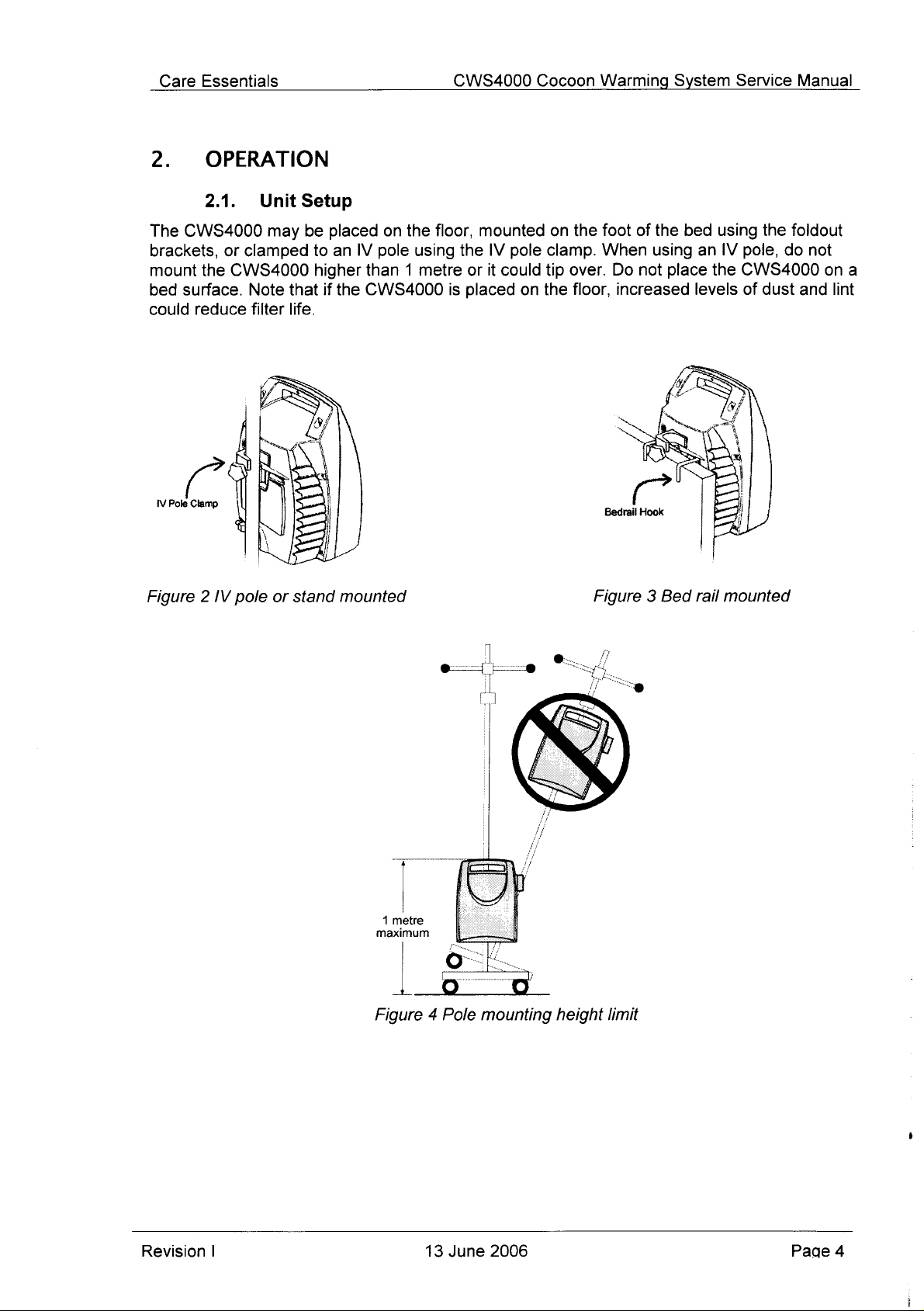
2.
The
brackets,
mount
bed
could
IV
OPERATION
2.1.
CWS4000
the
surface.
reduce
Pole
Clamp
Unit
may
or
clamped
CWS4000
Note
filter
Setup
be
to
higher
that
life.
placed
an
IV
than 1 metre
if
the
CWS4000
on
pole
the
using
floor,
the
or
is
placed
mounted
IV
pole
it
could
on
on
the
clamp.
tip
over.
the
floor,
foot
of
When
Do
not
increased
the
bed
using
place
using
an
IV
the
levels
the
foldout
pole,
do
CWS4000
of
dust
not
and
ona
lint
maximum
Revision
Figure 4 Pole
I
13
June
mounting
2006
height
limit
Page
4
Page 6
Care
Essentials
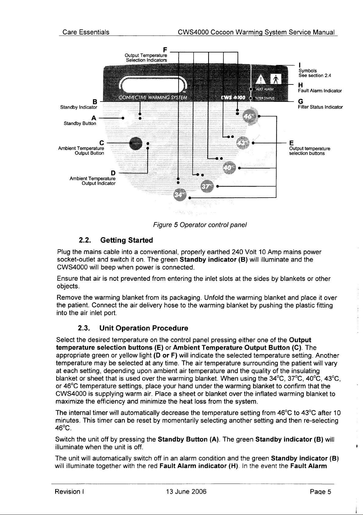
Output
Seiection
Temperature
Indicators
F
CWS4000
Cocoon
Warming
System
Service
|
Symbols
See
section
Fault
Manual
Alarm
2.4
Indicator
Standby
Ambient
Standby
Temperature
Output
Ambient
Indicator
A+
Button
Button
Temperature
Output
2.2.
Plug
the
mains
socket-outlet
CWS4000
Ensure
objects.
will
that
air
Indicator
Getting
cable
and
switch
beep
when
is
not
Figure 5 Operator
Started
into a conventional,
it
on.
The
green
power
prevented
is
connected.
from
entering
properly
Standby
the
control
earthed
indicator
inlet
slots
panel
240
(B)
at
the
Volt
will
sides
10
Amp
mains
illuminate
by
blankets
Filter
Output
temperature
selection
power
and
the
Status
buttons
or
other
Indicator
Remove
the
into
Select
temperature
the
patient.
the
air
inlet
2.3.
the
desired
warming
Connect
Unit
selection
appropriate green
temperature may
at
each
setting,
blanket
or
46°C
or
temperature
CWS4000
maximize
The
internal
minutes.
This
depending
sheet
is
supplying
the
efficiency
timer
timer
46°C.
Switch
illuminate
The
will
the
unit
when
unit
will
automatically
illuminate
off
the
together
blanket
the
port.
Operation
temperature
buttons
or
yellow
be
selected
that
is
used
settings,
warm
and
will
automatically
can
be
by
pressing
unit
is
with
air
delivery
light
upon
over
air.
minimize
reset
off.
switch
the red
from
its
packaging.
hose
Procedure
on
the
control
(E)
or
(D or
F)
at
any
time.
ambient
the
warming
place
your
Place a sheet
the
decrease
by
momentarily
the
Standby
off
in
an
Fault
to
the
Ambient
will
indicate
The
air
temperature
hand
heat
the
Button
alarm
Alarm
Unfold
warming
panel
pressing
Temperature
air
temperature
blanket.
under
loss
or
blanket
from
the
temperature
selecting
(A).
condition
indicator
the
When
warming
the
The
the
warming
blanket
either
Output
selected
surrounding
and
the
using
over
the
system.
setting
another
green
and
the
(H).
In
blanket and
by
pushing
one
of
Button
temperature
quality
blanket
of
the
34°C, 37°C,
to
inflated
from
setting
and
Standby
green
the
Standby
event
the
plastic
the
Output
(C).
setting.
the
patient
the
insulating
confirm
warming
46°C
to
then
indicator
the
Fault
place
it
over
fitting
The
Another
will
vary
40°C,
43°C
43°C,
that
the
bianket
after
to
re-selecting
(B)
will
indicator
(B)
Alarm
10
Revision
|
13
June
2006
Page
5
Page 7
Care
Essentials
CWS4000
Cocoon
Warming
System
Service
Manual
indicator
supply
The
indicator
Indication
Steady
Steady orange
Flashing
Steady
(H)
and
Filter
is
green
orange
red
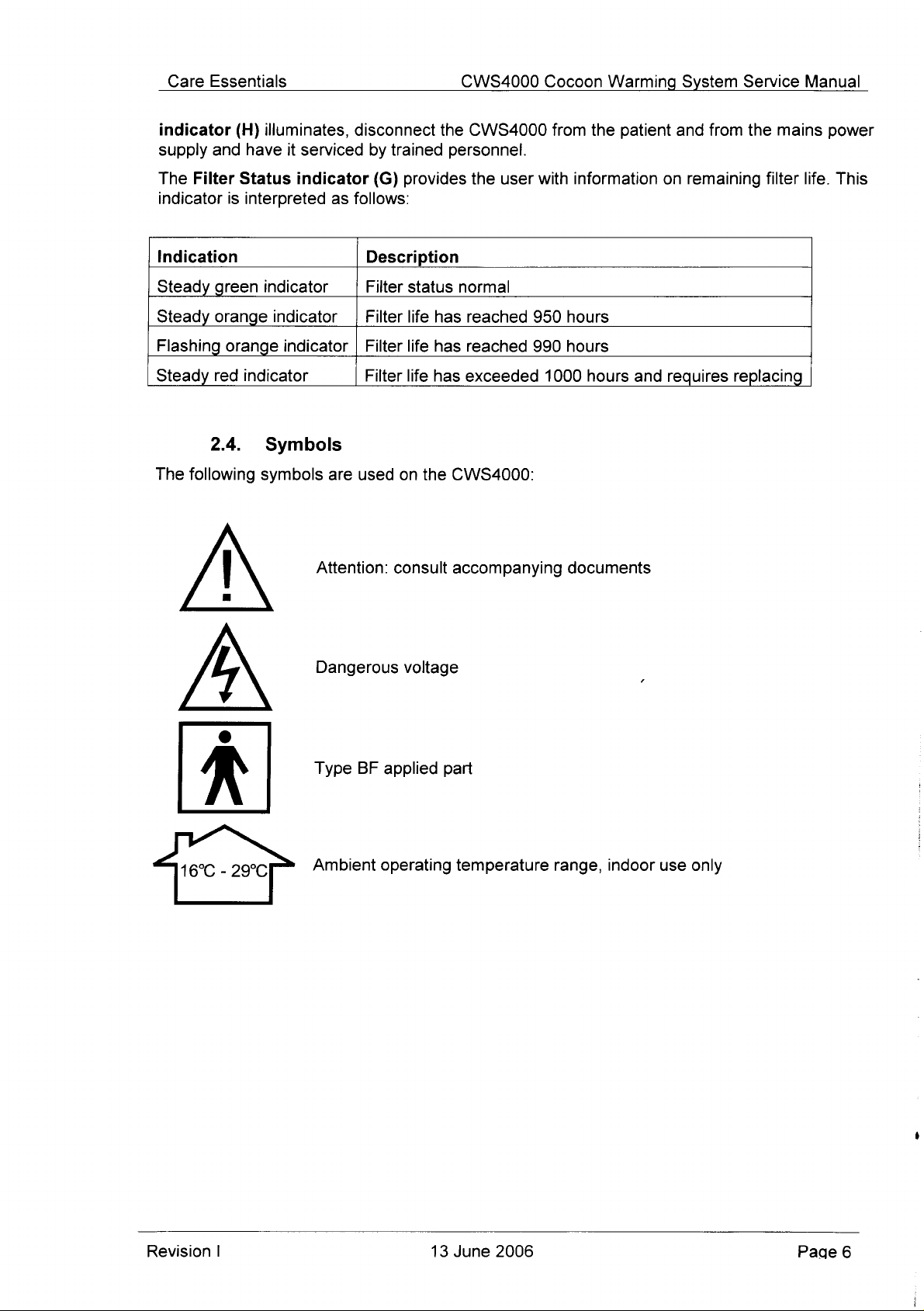
2.4.
The
following
个
illuminates,
have
it
serviced
Status
interpreted
indicator
as
indicator
indicator | Filter
indicator | Filter
indicator
Symbols
symbols
are
Attention:
disconnect
by
trained
(G)
provides
follows:
Description
Filter
status
life
life
Filter
used
life
on
the
consult
the
CWS4000
personnel.
the
user
normal
has
reached
has
reached
has
exceeded
CWS4000:
accompanying
from
with
950
990
1000
hours
hours
documents
the
patient
information
hours
and
and
from
on
remaining
requires
the
mains
filter
life.
replacing
power
This
A
16°C - 29°C
Dangerous
Type
BF
Ambient
voltage
applied
operating
part
temperature
range,
indoor
use
only
Revision
|
13
June
2006
Page
6
Page 8
Care
Essentials
CWS4000
Cocoon
Warming
System
Service
Manual
3.
Review
SAFETY
3.1.
e
Explosive
e
Risk
3.2.
e
Ensure
connector
e
The
biomedical
for
servicing
CWS4000
e
Ensure
inspections.
e
Inthe event
disconnected
e
Use
the
following
hazard.
of
electric
that
located
CWS4000
the
only
in
PRECAUTIONS
safety
Danger
Do
shock.
Warning
no
direct
or
indirect
on
the
must
only
electronics
medical
or
malfunction
CWS4000
of
excess
from
accordance
devices,
the
precautions
not
use
in
Disconnect
contact
rear
of
the
be
opened
technicians
and
could
otherwise
is
subjected
fluid
contact
mains
with
power
Operator
prior
the
presence
mains
is
made
CWS4000.
or
serviced
or
certified
in
accordance
to
the
with
the
supply
Manual
to
servicing
of
flammable
power
specified
before
between
clinical
result.
CWS4000
and
checked
by
with
instructions.
the
CWS4000.
servicing
the
patient
qualified
engineers
the
Service
routine
electrical
it
is
recommended
by
anaesthetic
the
CWS4000.
and
the
communications
personnel
familiar
qualified
such
Manual.
safety
personnel.
agents.
as
with
repair
Damage
and
that
the
certified
practices
to
the
performance
unit
be
3.3.
e
Operate
conditions
ο
When
e
The
46°C
circulation.
e
It
is
not
life
period.
3.4.
The
CWS4000
equipment — Part
compatibility — Requirements
vicinity
other
It
electromagnetic
interference
keeping
will
equipment
is
recommended
interconnecting
Caution
the
CWS4000
and
as
detailed
using
an
IV
pole,
setting
recommended
is
Electromagnetic
has
been
1:
General
not
be
affected
in
the
vicinity
that
compatibility
is
evident
or
not
designed
all
disruptive.
leads
only
in
the
in
Section
do
not
mount
recommended
that
the
unit
Interference
to
requirements
and
tests)
by
the
electromagnetic
may
affect
equipment
requirements
as
short
specified
11
below.
the
CWS4000
for
patients
be
operated
comply
used
Increasing
as
with
for
but
this
the
operation
near
for
possible
supply
after
IEC
safety.
does
emissions
the
CWS4000
that
equipment
the
distance
will
voltage
higher
who
601-1-2:2004
2.
Collateral
not
of
help
range
than 1 metre
are
non-responsive
the
filter
guarantee
from
the
CWS4000.
comply
and
between
reduce
and
environmental
has
exceeded
(Medical
standard:
that
other
the
CWS4000.
with
to
check
offending
the
effect.
or
it
could
tip
or
with
impaired
the
specified
electrical
electromagnetic
equipment
Similarly,
the
relevant
before
use
that
devices, and
over.
in
the
no
Revision
|
13
June
2006
Page
7
Page 9

Care
Essentials
CWS4000
Cocoon
Warming
System
Service
Manual
4.
PREVENTATIVE
4.1.
e
Clean
dampened
e
Clean
the
accumulated
4.2.
Care
Essentials
Information
technical
In
Australia,
e
e
standards.
AS3551
This
standard
for
medical
and
routine
safety
AS2500
This
equipment
patient
and
standard
and
installations
MAINTENANCE
Cleaning
CWS4000
with a non-staining
Electrical
recommend
on
the
type
the
relevant
Technical
specifies
devices.
testing
performance
Guide
provides a comprehensive
used
operator
to
be
of
to
in
health
used
dirt
and
Some
the
safety,
control
and
Safety
that
frequency
technical
management
procedures
medical
testing.
safe
care
for
panel,
lint
enclosure
hospital
from
the
Inspection
the
CWS4000
of
standards
programs
required
of
these
use
including
particular
include
devices.
of
electricity
facilities.
medical
exterior,
disinfectant.
air
inlet
slots
receive
inspections
are:
for
medical
to
develop
procedures
This
standard
in
patient
guide
Measures
details
of
to
the
procedures.
and
hose
using a vacuum
regular
may
be
obtained
devices.
equipment
for
acceptance,
specifies
care.
the
safe
use
are
detailed
classes
of
with a soft
electrical
safety
from
management
electrical
of
electrically
to
provide
equipment
cloth
cleaner.
inspections.
locally
fault
management
safety,
operated
and
maintain
and
electrical
lightly
published
programs
essential
Programmed
patient
apply.
safety.
electrical
Mandatory,
safety
statutory
inspections
requirements
are
essential
to
for
electrical
confirm
safety
continued
inspections
operator
may
and
also
Revision
|
13
June
2006
Page
8
Page 10

Care
Essentials
CWS4000
Cocoon
Warming
System
Service
Manual
4.3.
Care
Essentials
inspection
calibration.
Items
e
CWS4000
»
Digital
STEP
1
2
3
4
to
Required:
Thermometer.
If
you
have
e
Place
e
Do
e
Connect
Familiarise
the
CWS4000
The
temperature
e
Ensure
e
Ensure
condensing.
e
Place
Figure
«
Check
set
e
Check
e
Note
possible
will
compressed
Performance
recommend
verify
CWS4000
Operator & Service
not
already
the
CWS4000
not
connect
the
CWS4000
yourself
Operator
control
the
delivery
that
the
the
digital
6.
that
the
temperature
temperature.
that
the
temperature
that
some
because
depend
on
the
or
extended.
that
done
on a firm,
the
delivery
with
the
and
system
hose
environmental
thermometer
variation
of
heat
ambient
Inspection
the
CWS4000
functions.
so,
read
hose
to
mains
operation
Service
is
cover
of
of
between
loss
temperature
The
Manuals.
the
level
surface.
to a warming
power.
of
the
Manuals.
verified
is
undamaged
conditions
sensor
in
delivered
delivered
the
set
that
occurs
receive
CWS4000
PROCEDURE
CWS4000
CWS4000
as
follows:
and
are
20°C
the
centre
air
stabilises
air
corresponds
temperature
in
the
and
the
Operator
blanket.
by
operating
that
it
to
22°C,
of
the
within
and
delivery
degree
to
at
least
does
not
and
Service
covers
the
30%
to
delivery
five
(5)
with
the
set
temperature
hose.
The
which
the
an
annual
require
Manuals.
the
CWS4000
entire
70%
relative
hose
outlet
minutes
temperature
of
magnitude
hose
performance
adjustment
with
reference
hose.
humidity,
as
shown
in
following a change
to
within
delivered
is
air
is
of
the
heat
longitudinally
or
to
non-
in
+2°C.
loss
Revision
Figure 6 Delivery
|
Temperature
hose
outlet
13
June
Sensor
showing
2006
temperature
sensor
position
Page
9
Page 11

Care
Essentials
CWS4000
Cocoon
Warming
System
Service
Manual
4.4.
The
the
CWS4000
performance
The
series-connected
exhaust
exceed a predetermined
remove
automatically
This
various
temperature
that
delivery
less
the
performed
Items
Temperature
CWS4000
discretion
maximum
air
power
test
procedure
items
switches
hose
than 8 minutes
test
may
Required:
e
CWS4000
temperature
of
temperature
inspection.
delivered
stream
from
restoring
required
of
46°C
the
air
be
as
at
an
those
bimetallic
and
the
may
until
heater
temperature
after
high
ambient
Operator
Limit
responsible
power
to
Thermostat
limit
thermostat
limit
thermostat
air
temperature
auto-resetting
will
interrupt
limit.
Either
CWS4000
when
be
briefly
perform
it
has
“warmed
on
continuously,
are
the
test
as
60°C.
temperature
and
Service
Test
test
for
the
technical
function
is
not
thermostats.
power
of
if
the
the
described
the
to
these
delivered
thermostat
test.
The
up.”
the
two
as
The
simulating a possible
monitored. The
start.
The
delivery
Note
that
this
of
21°C,
Manuals.
Procedure
is
completely
management
does
not
only
limited
These
CWS4000
independently
air
exceeds a preset
temperature
follows.
CWS4000
test
test
or
greater.
test
is
hose
will
The
is
passed
only
optional
of
the
require
by
is
commenced
air
adjustment,
the
control
thermostats
should
CWS4000
energised
temperature
produce a valid
the
operating
fails
fault
condition.
if
the
and
may
be
performed
CWS4000.
system
are
output
thermostats
high
limit
to a safe
is
set
and
operated
through a special
CWS4000
at
the
result
The
calibration
but
by
located
air
temperature
temperature,
level.
up
with
The
test
is
de-energised
conclusion
if
it
or
two
in
the
will
the
at a set
process
time
of
is
at
and
In
the
Care
A.
C.
e
Personal
Terminal
e
Digital
e
CWS4000
The
Cocoon
test
cable.
This
cable
Details
B.
of
Machines
Machines
Machines
event
Essentials
Computer
program,
Thermometer.
RS232-Logic
Warming
is
for
the
the
three
with
with
with
you
need
Pty
Ltd.
(PC)
eg
Machine
over
versions
Serial
Serial
Serial
to
access
with a free
HyperTerminal™,
Communications
model
temperature
are:
Numbers
Numbers
Numbers
any
CSW4000
performance
commencing
commencing
commencing
of
these
serial
communications
which
Cable
4-0001
4-0100
4-0200
cables
is
provided
can
have
testing.
please
with
three
Yellow
Red
Green
contact
(Com)
Microsoft
different
Dot
Dot
Dot
your
location
port
and a suitable
Windows™,
versions
Distributor
for
the
or
Revision
|
13
June
2006
Pade
10
Page 12

Care
Essentials
STEP
1
If
you
have
not
already
all
of
this
2
e
e
e
3
e
e
e
e
4
Place
above.
5
e
e
e
6
While
as
e
e
e
e
7
Follow
e
e
e
e
e
e
e
8
e
e
9
Confirm
in
Section
procedure.
Place
the
CWS4000
Do
not
connect
Disconnect
Locate
the
enclosure
Locate
the
small
Insert
the
cable
Insert
the
cable
the
digital
Connect
Select
Operate
commencing
follows:
Select
Baud
Terminal
Append
When a correct
received
Press
Press
The
To
To
The
minutes.
Confirm
Disconnect
Disconnect
the
the
46°C
the
the
CWS4000
the
Com
rate — 9600,
emulation — VT100,
line
the
instructions
every
the
spacebar
“T”
to
46°C
temperature
initiate
the
stop
the
test,
CWS4000
that
the
the
that
the
CWS4000
4.3
above.
the
the
CWS4000
black
plug
D-connector
thermometer
CWS4000
temperature
CWS4000
the
thermostat
is
port
feeds
shown
connection
second.
display
over-temperature
press
is
deemed
the
thermostat
CWS4000
cable
done
so,
read
on a firm,
PVC
delivery
from
rear with
cable
socket
into
the
socket.
into a free
sensor
to
mains
setting.
on
the
46°C
test.
“warming
connected
data
to
incoming
to
the
from
up”,
bits — 8,
character
on
the
is
established
display
the
over-temperature
setting
must
any
key
to
have
resets
from
the
CWS4000
functions
CWS4000
PROCEDURE
the
CWS4000
level
surface.
hose
to a warming
mains
power.
the
warning
on
the top
It
should
Com
in
the
centre
power.
temperature
start
the
Terminal
to
the
Converter
parity — none,
set — ASCII.
line
ends — enabled.
Terminal
root
thermostat
or
change
mains
correctly
screen.
be
selected
passed
after
power.
window:
between
thermostat
the
the
several
and
by
Cocoon
Instruction
label.
left
of
snap
port
connector
of
the
setting
cable
flow
control — none.
the
in
order
test,
SLOWLY
CWS4000
test
if a thermostat
minutes,
PC.
undertaking a performance
blanket.
the
enclosure
into
place.
delivery
for
program
in
Step 4 above.
CWS4000
test
screen.
for
type,
temperature
restoring
Warming
Manual
on
the
hose
outlet
at
least
on
the
and
the
test
“YES”
trips
power
to
System
and
Service
rear.
PC.
as
10
minutes
PC
and
the
proceed.
then
setting.
in
under
to
inspection
Service
Manual.
shown
prior
select
PC, a dot
press
the
eight
the
CWS4000.
in
Figure
to
the
settings
(.)
Enter
(8)
as
detailed
Manual
Read
6
is
key.
Revision
|
13
June
2006
Page
11
Page 13

Care
Essentials
CWS4000
Cocoon
Warming
System
Service
Manual
4.5.
The
CWS4000
the
CWS4000
STATUS
Items
e
e
e
e
Required:
CWS4000
Philips
13mm
HEPA
STEP
1
If
2
e
e
e
3
e
e
e
e
4
e
e
e
e
5
e
e
‧
e
e
e
6
Replace
7
Confirm
in
Filter
has a replaceable
every
indicator
Number 1 and 2 Screwdrivers.
spanner.
will
Operator € Service
filter.
you
have
not
Place
the
Donot
connect
Disconnect
Locate
the
Remove
Remove
enclosure
To
pull.
Remove
Remove
Install
Replace
Connect
present
Read
followed
Mark
Record
Reset
meter
successful
Disconnect
Section
the
the
disconnect
Do
not
the
the
the
the nut
the
on
and
by
the
HEPA
these
the
filter
display. A steady
the
rear
that
the
4.3
above.
Replacement
1000
operating
warn
of
already
CWS4000
enclosure
front
new
some
note
an
reset
the
the
the
CWS4000
seven
enclosure
and
the
membrane
pull
the
nut
and
old
HEPA
HEPA
and
CWS4000
internal parts
the run
“h",
“r’,
filter
figures
life
1000-hour
of
CWS4000
panel
by
CWS4000
done
on a firm,
PVC
(7)
rear.
tail
washer
filter.
washer
with
in
the
reversing
HEPA
hours
the
need
Manuals.
so,
read
level
delivery
from
mains
rear
with
the
Philips
head
rear
being
keypad
itself,
as
damage
securing
filter
and
discard.
securing
to
mains
power.
of
hour
meter
and a pause.
the
hour
the
CWS4000
counter
green
FILTER
1000-hour
from
mains
step 5 above.
functions
correctly
filter.
or
for
filter
PROCEDURE
the
CWS4000
surface.
hose
to a warming
power.
warning
screws
careful
tail
will
the
the
Exercise
the
CWS4000.
on
the
meter
reading
service
by
pressing
STATUS
counter.
power.
Under
12
label.
located
not
from
HEPA
HEPA
control
by
normal
months,
replacement.
Operator
blanket.
around
to
stress
the
Control
almost
certainly
filter.
filter.
care,
board.
and
date
record.
and holding
indicator
undertaking a performance
use,
whichever
and
the
cable
assemblies
Board,
result.
as
there
Hour
digits
of
replacement.
the
and a long
replace
occurs
Service
perimeter
hold
will
be
are
switch
beep
the
HEPA
first.
Manuals.
of
the
enclosure
that
run
between
the
blue
connector
dangerous
sequentially
in
will
inspection
front
of
indicate
voltages
filter
The
FILTER
rear.
the
and
displayed
the
hour
the
as
detailed
inside
Revision
|
13
June
2006
Page
12
Page 14

Care
Essentials
CWS4000
Cocoon
Warming
System
Service
Manual
5.
TROUBLESHOOTING
5.1.
e
Make
e
Check
e
Check
e
Check
e
Check
blanket.
adhesive
e
Request
e
Check
5.2.
e
Extremely
can
cause
the
STANDBY
this
occurs,
automatically
Warming
sure
the
both
ends
the
delivery
that
there
the
warming
Small
tape.
qualified
for
fault
Standby
high
the
simply
Blanket
CWS4000
of
the
hose
are
no
blanket
rips
or
tears
service
alarm.
Indicator
storage
temperature
indicator
wait
reset
and
Will
is
plugged
delivery
and
obstructions
personne!
hose
warming
for
damage.
in
the
warming
Will
temperatures
limit
thermostats
will
fail
to
light
for
the
CWS4000
the
STANDBY
Not
Inflate
in
to
an
for
proper
blanket
to
the
If
air
check
Not
Light
(such
when
to
indicator
energized
connection.
inlet
for
kinks.
air
inlet
slots.
is
flowing
blanket
for a clogged
as
in
the
cool
may
those
the
CWS4000
CWS4000
down
will
light.
found
mains
from
the
be
temporarily
or
dirty
motor
is
and
eventually
power
to
socket-outlet.
hose,
try
repaired
filter.
cars
on
actuate.
connected
the
another
with
hot
summer
Should
to
thermostats
mains
this
power.
warming
days)
occur,
If
will
e
Request
5.3.
Repairs
biomedical
servicing
the
6.
This
printed
to
CWS4000
SCHEMATIC
section
circuit
diagrams
The
following
e
The
schematic
e
Electrical
e
Netlabels
logic
“0”
The
CWS4000
qualified
Equipment
the
CWS4000
electronics
medical
devices,
or
malfunction
describes
board
contained
should
connectivity
(signal
(eg:
/SIGNAL).
Control
service
personnel
Repairs
should
technicians
and
in
may
DIAGRAM
the
CWS4000
(PCB)
in
diagrams
component
Section 8 below.
assist
is
names)
Board
with
are
shown
are
implements
check
be
preformed
or
clinical
accordance
otherwise
DESCRIPTION
schematic
legend
the
interpretation
organised
by
prefixed
in a flat
continuous
with a forward
the
for
blown
by
qualified
engineers
with
the
result.
diagrams.
contained
of
the
structure.
wires
following
mains
personnel
familiar
CWS4000
Reference
in
Section 7 and
Schematic
or
net
labels
slash
when
functions:
power
with
repair
Service
Diagrams:
on
they
fuses.
such
as
practices
Manual.
should
the
partial
are
certified
for
Damage
be
made
schematic
wires.
asserted
to
the
with
to
e
Microcontroller.
»
RS232
ο
Microcontroller
e
Fan
control.
e
Heater
Revision
|
transceiver
reset
control.
(Control
circuit.
Board
revision E and
13
June
2006
later).
Page
13
Page 15

Care
Essentials
e
LED
e
Run
e
Filter
e
Buzzer.
e
Power
The
CWS4000
»
Digital
e
Temperature
The
more
display
hour
life
drivers.
meter
hour
supplies.
Sensor
temperature
limit
important
display.
counter
Board
sensor.
thermostats.
of
these
reset
switch.
implements
functions
CWS4000
the
are
elaborated
Cocoon
following
functions:
below.
Warming
System
Service
Manual
6.1.
Microcontroller
The
microcontroller
e
CPU.
e
Program
e
RAM.
e
EEPROM.
ο
Interrupt
e
External
e
Counter/Timers.
e
Watchdog
e
Digital
The
microcontroller
e
Monitors
Monitors
ROM.
controller.
interrupts.
Input/Output
the
the
Control
(U1)
timer.
performs
exhaust
push-button
Board
integrates a number
ports.
the
following
air
temperature
switches.
of
functions:
functions:
through
the
digital
temperature
sensor.
Controls
Controls
The
microcontroller
software
microcontroller
Reset
When
e
e
the
Digital
Signal
The
e
Signal
The
Thus
the
with
the
Revision
the
the
program
Circuit
microcontroller
Input/Output
/FAN
fan
blower
/HEAT
heater
reset
heater
|
display
heater
ROM
contained
fault,
Care
goes
is
switched
goes
is
switched
process
being
turned
and
buzzer
and
fan.
is
factory
in
Essentials
is
reset
ports 0 — 3 go
low
switching
drivers.
programmed
the
microcontroller
must
either
high.
on
the fan
on.
high
switching
off
off.
implements a safety
on.
13
with
ROM
fit a replacement
by
power-on
relay.
the
June
heater
strategy
2006
triac.
the
application
is
subject
or
by
the
to
prevent
part.
watchdog
the
software
to
copyright.
timer:
fan
biower
program.
In
the
event
being
turned
Page
The
14
of
off
a
Page 16

Care
Essentials
CWS4000
Cocoon
Warming
System
Service
Manual
Power-On
Following
connected
asserted
internal
Watchdog
The
microcontroller
When a watchdog
To
prevent
overflows
software
watchdog
microcontroller
occurring.
Digital
The
temperature
microcontroller
Temperature
Reset
power-on
to
ground.
high.
The
power-on
Reset
such a system
by
the
malfunction,
timer.
from
6.2.
Temperature
Sensor
(U1).
Limit
capacitor
This
causes
microcontroller
reset
circuit
watchdog
timer
overflow
reset
application
the
application
This
failure
running
Board
Sensor
sensor
(U1)
Thermostats
(C3)
charges
the
Reset
type
used
and
capacitor
timer
is
incremented
occurs
the
software
will
produce a system
out
of
is
controlled
the
microcontroller
program.
software
control.
from
zero
to
+5V
input
of
the
microcontroller
on
Control
(C3),
resistor
microcontroller
Board
(R1)
regularly
watchdog
If
the
microcontroller
program
This
prevents a potentially
by
and
will
fail
reset
on
overflow
communicates
(VCC)
by
is
timer
through
revision E and
and
diode
the
microcontroller
reset.
is
reloaded
suffers a hardware
to
load
thus
with
the
resistor
to
be
momentarily
later
(D1)
are
before
the
microcontroller
preventing
hazardous
Control
(R1)
has
an
not
fitted.
hardware.
it
or
the
situation
Board
from
The
maximum
connected
air
stream
predetermined
calibration
bimetallic
and
or
performance
6.3.
The
System
CWS4000
e
Power
e
Temperature
e
Heater.
e
Fan
e
Control
e
Sensor
e
Communications
Before
make a careful
compromise
Block
electrical
inlet
blower.
Board.
Board.
removing
patient
air
temperature
auto-resetting
will
interrupt
limit.
The
System
Diagram
and
module
limit
connector.
any
of
note
so
safety
is
power
temperature
inspection.
Block
electronic
including
thermostats.
the
that
Diagram
shows
EMI
connections
these
and/or
not
only
limited
thermostats.
to
the
CWS4000
limit
thermostat
the
general
subassemblies:
filter
and
between
may
be
correctly
damage
the
by
the
These
should
function
electrical
fuses.
the
electrical
reinstated.
CWS4000.
control
thermostats
connectivity
system
the
output
does
and
Incorrect
but
by
are
located
air
temperature
not
require
between
electronic
connections
two
series-
in
the
exhaust
exceed
adjustment,
the
various
subassemblies,
could
a
The
warrant
Revision
System
extensive
|
Block
Diagram
discussion.
is
presented
13
as
June
an
aid
2006
to
understanding
the
CWS4000
and
Page
does
15
Page 17

Care
Essentials
CWS4000
Cocoon
Warming
System
Service
Manual
7.
BOARD
7.1.
COMPONENT
Control
Board
LEGENDS
ーー
ον
>
Not
fitted
when
U1
AT89S8253
is
Revision
|
13
June
2006
Page
16
Page 18

Care
Essentials
CWS4000
Cocoon
Warming
System
Service
Manual
7.2.
Sensor
Board
Revision
|
13
June
2006
Page
17
Page 19

Care
Essentials
CWS4000
Cocoon
Warming
System
Service
Manual
8.
SCHEMATIC
8.1.
Control
vo
D8
|
>
cuvonvet
DIAGRAMS
Board
Schematic
GO9daA3X
Nid
03045
Diagram
Нот
@aGPSMND
AdhHy
COMITE
4220
z
Cd
Ag
OA
uiñesg]
SIUILNASSS
TOROS
ALDO
3739113
MANDA
MAIS
SÅ
AS
140)
τν
SII
EN
aue8
o
a
απο
「 マ すす
すす
すす
1
<a
-O
ea
RI
49
を 5
ZHHZ6SB'T
TX
ΒΡΤΥΝ
Y
1465
4082
MORA
a-ge-r
v
080092
na
TLE
3n1
UALVAH
199
2
aneaz
ZIBLIGLA
TATE
AZEZ
Auge
875
05202
Y
anger
301
VHLNIN
UALVAH
139
NUM
Nus
vaLnan
sa
8089
8522
anges
HAl
Alddns
LOV
SuJnaN
Aldans
Revision
|
13
June
2006
Page
18
Page 20

Revision
Care
|
13
June
2006
8.2.
Sensor
Board
Schematic
Diagram
Essentials
CWS4000
Cocoon
Warming
Page
19
System
с
o - и 一 >
a
Service
Manual
Page 21

UOISIASY
|
CONTROL
Black
Unite
Yellou
Red
Red
Yelloy
Black
BOARD
TEST
(Rear)
SENSOR
N/C
—
53Cdeg,
S1
THERMOSTATS
o
Pi
...
BOARD
o“
53Cdeg
$2
o
UU91SAS
aed
58
sjenuassy
EL
eunr
9002
POWER
Fi
Ta
6.3A
+
MEMBRANE
ENTRY
a .
T
Ay
|!
Φος
KEYPAD
MODULE
L
PZ
li
ου
Cy
T
MOU
ASSEMBLY
Thick
Thin
Thick
Thick
Brown
Blue
Red
Bive
HEATER
Title
CARE
“af
ESSENTIALS
CSRUECT
YSTEM
IVE
BLOCK
WARNING
DIAGRÁM|
cus4e
Revision
Y90Jg
we1Geig
0007SM3
uo0909
BuruieMm
wa]sAs
89InJos
sbed
0Z
[ΕΠΙΕΙΛΙ
Page 22

Care
Essentials
CWS4000
Cocoon
Warming
System
Service
Manual
9.
PARTS
9.1.
LIST
General
PART
NO
Assembly
DESCRIPTION
Revision
|
13
June
2006
Page
21
Page 23

Care
Essentials
CWS4000
Cocoon
Warming
System
Service
Manual
CIRCUIT
DESIG.
9.2.
Control
MANUF.
Board
PART
NO
DESCRIPTION
Note:
R1,
D1
Revision
and C3
|
are
not
fitted
when
13
U1
June
is
an
AT89S8253-24PC.
2006
Page
22
Page 24

Care
Essentials
CWS4000
Cocoon
Warming
System
Service
Manual
9.3.
Sensor
Cie! | MANUF.
DC1
P1
U1
10.
The
operation
warranty
replace
authorization
full
warranty
Any
Any
Any
Keystone
TI
Muiticomp
Molex
Dallas
WARRANTY
CWS4000
for a period
in
place
at
its
sole
prepaid
is
Maxim
is
warranted
at
option,
available
Board
PART
TBC
TBC
TBC
8916
1NTO1-L53-11
100nF
22-27-2031
|DS18B20
of
two
time
of
free
to
Care
from
NO
50V
free
of
defects
years,
purchase.
under
of
charge,
Essentials.
Care
Essentials
Screw,
Zinc-Plated
Nut
Zinc-Plated
Washer,
LED
Spacer
Switch,
Capacitor,
Header,
Pitch
Thermometer,
During
Thermal,
Square
in
the
any
defective
Consumable
Steel,
Internal
material
terms
the
upon
S/proof
0.4"
NC,
Ceramic,
Pin,
Digital,
and
warranty
request.
DESCRIPTION
Steel,
Pan-Head,
M3
Zinc-Plated
53°C
Opening
Z5U,
50V,
0.2"
Friction
and
parts
items
Lock,
0.0625°C
conditions
Precision
workmanship
period,
or
products
such
PCB
of
Care
as
M3x6
Steel,
M3
Temperature
Pitch
Mount, 3 Way,
(TO-92)
under
the
Care
Essentials
returned
filters
are
0.1"
normal
Essentials
excluded.
will
with
use
repair
prior
QTY
4
4
4
1
2
1
1
1
and
or
The
This
warranty
are
no
obligations
connection
warranties
a
particular
This
warranty
power
cords,
does
not
on
with
the
use
including
purpose.
does
or
but
not
accessory
cover
the
cover
part
or
not
products
of
Care
performance
limited
blankets.
the
following
to,
abused,
Essentials
of
the
misused,
the
product.
implied
accessories
or
for
consequential
Care
warranties
or
consumables;
altered
Essentials
of
outside
damages
disclaims
merchantability
filters,
the
factory.
arising
and
hose
out
all
implied
of
covers,
There
of
or
in
fitness
for
Revision
|
13
June
2006
Page
23
Page 25

Care
Essentials
CWS4000
Cocoon
Warming
System
Service
Manual
11.
ELECTRICAL
Supply
Supply
Supply
External
Heater
Fan
CLASSIFICATION
Applied
Applied
Device
Mode
Degree
Degree
anaesthetic
Environmental
Environmental
storage
Method
PERFORMANCE
Temperature
temperature
Temperature
ambient
Environmental
specified
Time
accuracy
temperature
SAFETY
Dual
Heater
Temperature
Control
PHYSICAL
Dimensions
Weight
Enclosure
Filter
Filter
Revision
SPECIFICATIONS
Voltage
Frequency
Power
Fuses
Motor
Parts
Part
classification
ciassification
of
operation
of
protection
of
safety
mixtures
of
disinfection
at
temperature
temperature
required
of
delivered
setting
SYSTEMS
temperature
temperature
system
type
life
|
in
the
conditions
conditions
settings
the
end
accuracy
conditions
to
attain
limit
limit
limit
alarm
failure
against
presence
with
indicate
of
of
delivered
setting
required
accuracy
the
air
following a change
thermostats
devices
alarm
ingress
of
liquid
of
flammable
air/oxygen/nitrous
reguired
required
the
the
average
delivery
specified
for
operation
for
transport and
hose
air,
except
to
achieve
temperature
oxide
air
the
in
230 — 240
50
1100
2 x 6.3
1000 Watt
45
Warming
Type
Class
Continuous
No
Not
with
16°C
10°C
Surface
staining,
Ambient,
Note:
temperature,
placed
+
for
2°C
the
Not
20°C
5
minutes
Either
from
A
98°C
from
Continuous
delivered
Continuous
functions
29
cm x 22
6
Kilograms
Flame-Retardant
Bacteriological
1000
13
June
Vac
Hz
Watts
Maximum
Amp
250V
Time
heating
element
Watt
Blanket & Delivery
BF
1
protection
designed
atr/oxygen/nitrous
to
to
specified
to
the
excessive
hours
against
for
29°C,
Less
40°C,
45%
disinfection
disinfectant
34°C,
37°C,
The
air
temperature
the
on top
of
with
delivery
without
22°C,
30%
of
two
independent
CWS4000
thermal
fuse
temperatures.
temperature
air
maintains
self-monitoring
predictably.
cm x 40
HEPA
2006
use
than
to
is
warming
the
warming
hose
to
if
and
cm
ABS-PC
Lag
ingress
in
the
presence
oxide.
90%
95%
relative
possible
solution.
40°C,
43°C
around
blanket
cover.
delivery
70%
relative
53°C
the
delivered
104°C
monitoring
its
specified
by the
Plastic
filter
(T)
Hose
of
relative
blanket.
hose
5x20mm
liquid
of
flammable
humidity,
humidity,
using a cloth
or
46°C
the
type
cover.
humidity,
self-resetting
air
self-resetting
guarantees
accuracy.
control
non-condensing
moistened
patient
is
and
the
non-condensing
thermostats
exceeds a preset
thermostat
system
anaesthetic
non-condensing
with a mild,
affected
use
that
of
an
the
temperature
ensures
by
the
insulating
removes
limit
protect
that
mixtures
non-
ambient
blanket
power
temperature.
the
filter
of
the
it
always
Page
24
air
Page 26

Care
Essentials
CWS4000
Cocoon
Warming
System
Service
Manual
12.
APPROVALS
Revision
|
13
June
2006
Page
25
 Loading...