

Page 1
COC Display Devices Co., Ltd. TENTATIVE No. :
( ◎ ) Preliminary Specification
( ) Final Specification
Title PM50H2000 (50˝HD MODULE )
Buyer Name Supplier
Product Specification of 50HD-PDP Module
CUSTOMER
APPROVAL
SPECIFICATION
COC Display Devices
Co., Ltd.
Model Name PM50H2000 Model Name PM50H2000
PART No. PART No.
Signature / Date Signature / Date
Approved by Approved by
Please return 1 copy for our confirmation
with your signature
COC Display Devices Co., Ltd.
Rev. No. : 0.0 2009. 12. 18. 1/37
Page 2
COC Display Devices Co., Ltd. TENTATIVE No. :
Product Specification of 50HD-PDP Module
Record of Revisions
Revision
No.
0.0
Effective
Date
2009. 12. 18
Comments
- Establishment
Rev. No. : 0.0 2009. 12. 18. 2/37
Page 3

COC Display Devices Co., Ltd. TENTATIVE No. :
Product Specification of 50HD-PDP Module
CONTENTS
0. WARNINGS AND CAUTIONS 4
□ Warning 4
□ Caution 5
1. GENERAL DESCRIPTION 9
□ Description 9
□ Features 9
□ Applications 9
□ Electrical Interface of Plasma Display 9
□ General Specifications 10
2. ELECTRICAL SPECIFICATIONS 11
□ Input Power Specifications 11
□ Power Sequence 12
□ LVDS Connection 13
□ Input Signal Timing (Non-interlaced Mode) 17
□ I2C Timing Specification & Register Description 19
3. ELECTRO OPTICAL SPECIFICATIONS 25
□ Electro Optical characteristic Specifications (60Hz) 25
□ Electro Optical characteristic Specifications (50HZ) 25
4. MECHANICAL AND ENVIRONMENTAL SPECIFICATIONS 26
□ Mechanical Characteristic Specifications 26
□ Vibration and Drop Specifications 26
□ Environmental Conditions 26
5. IMAGE STICKING CHARACTERISTICS 27
6. OUTLINE DRAWING 28
□ Front View 28
□ Rear View 29
7. CONNECTORS AND CONNECTIONS 30
8. LABEL 31
9. PACKING 34
* APPENDIX 35
□ Cell Defect Specifications 35
□ Scratch and Dent Specification 36
□ Sound Pressure Level Specification 36
Rev. No. : 0.0 2009. 12. 18. 3/37
Page 4
COC Display Devices Co., Ltd. TENTATIVE No. :
Product Specification of 50HD-PDP Module
0. Warnings and Cautions
WARNING indicates hazards that may lead to death or injury if ignored.
CAUTION indicates hazards that may lead to injury or damage to property if ignored.
!!
1) This product uses a high voltage (450 V max.). Do not touch the circuitry of this product with your hands
WARNING
when power is supplied to the product or immediately after turning off the power. Be sure to confirm that the
voltage is dropped to a sufficiently low level.
2) Do not supply a voltage higher than that specified to this product. This may damage the product and may
cause a fire.
3) Do not use this product in locations where the humidity is extremely high, where it may be splashed with
water, or where flammable materials surround it. Do not install or use the product in a location that does no
satisfy the specified environmental conditions. This may damage the product and may cause a fire.
4) If a foreign substance (such as water, metal, or liquid) gets inside the product, immediately turn off the power.
Continuing to use the products it may cause fire or electric shock.
5) If the product emits smoke, an abnormal smell, or makes an abnormal sound, immediately turn off the power.
If noting is displayed or if the display goes out during use, immediately turn off the power. Continuing to use
the product as it is may cause fire or electric shock.
6) Do not disconnect or connect the connector while power to the product is on. It takes some time for the
voltage to drop to a sufficiently low level after the power has been turned off. Confirm that the voltage has
dropped to a safe level before disconnecting or connecting the connector. Otherwise, this may cause fire,
electric shock, or malfunction.
7) Do not pull out or insert the power cable from/to an outlet with wet hands. It may cause electric shock.
8) Do not damage or modify the power cable. It may cause fire or electric shock.
9) If the power cable is damaged, or if the connector is loose, do not use the product; otherwise, this can lead to
fire or electric shock.
10) If the power connector or the connector of the power cable becomes dirty or dusty, wipe it with a dry cloth.
Otherwise, this can lead to fire.
Rev. No. : 0.0 2009. 12. 18. 4/37
Page 5
COC Display Devices Co., Ltd. TENTATIVE No. :
Product Specification of 50HD-PDP Module
CAUTION
!
!
□ General
1) Do not place this product in a location that is subject to heavy vibration, or on an unstable surface such as an
inclined surface. The product may fall off or fall over, causing injuries.
2) When moving the product, be sure to turn off the power and disconnect all the cables. While moving the
product, watch your step. The product may be dropped or fall, leading to injuries of electric shock.
3) Before disconnecting cable from the product, be sure to turn off the power. Be sure to hold the connector when
disconnecting cables. Pulling a cable with excessive force may cause the core of the cable to be exposed or
CAUTION
break the cable, and this can lead to fire or electric shock.
4) This product should be moved by two or more persons. If one person attempts to carry this product alone,
he/she may be injured.
5) This product contains glass. The glass may break, causing injuries, if shock, vibration, heat, or distortion is
applied to the product.
6) The temperature of the glass surface of the display may rise to 80°C or more depending on the conditions of
use. If you touch the glass inadvertently, you may be burned.
7) Do not poke or strike the glass surface of the display with a hard object. The glass may break or be scratched. If
the glass breaks, you may be injured.
8) If you glass surface of the display breaks or is scratched, do not touch the broken pieces or the scratches with
bare hands. You may be injured.
9) Do not place an object on the glass surface of the display. The glass may break or be scratched.
□ Design
1) This product may be damaged if it is subject to excessive stresses (such as excessive voltage, current, or
temperature). The absolute maximum ratings specify the limits of these stresses, and system design must
ensure that none of the absolute maximum ratings are exceeded.
2) The recommended operating conditions are conditions in which the normal operation of this product is
guaranteed. All the rated values of the electrical specifications are guaranteed within these conditions.
Always use the product within the range of the recommended operating conditions. Otherwise, the reliability
of the product may be degraded. Use of the product with a combination of parameters, conditions, or logic
not specified in the specifications of this product is not guaranteed. If intending to use the product in such a
way, be sure to consult COC in advance.
Rev. No. : 0.0 2009. 12. 18. 5/37
Page 6

COC Display Devices Co., Ltd. TENTATIVE No. :
Product Specification of 50HD-PDP Module
3) This product emits near infrared rays (800 to 1000nm) that may cause the remote controllers of other electric
products to malfunction. To avoid this, use an infrared absorption filter and thoroughly evaluate the system
and environment.
4) This product uses high-voltage switching and a high–speed clock. A system using this product should be
designed so that it does not affect the other systems, and should be thoroughly evaluated.
5) The materials which contain sulfur are forbidden to use, because they may damage PDP module.
6) This product has a glass display surface. Design your system so that excessive shock and load are not applied
to the glass. Exercise care that the vent at the corner of the glass panel is not damaged. If the glass panel or
vent is damaged, the product is inoperable.
7) There are some exposed components on the rear panel of this product. Touching these components may cause
an electric shock.
8) This product uses a high voltage. Design your system so that any residual voltage in this product is dissipated
quickly when power is turned off, observing the specifications.
9) This product uses heat-emitting components. Take the heat emitted by these components into consideration
when designing your system. If the product is used outside the specified temperature range, it may
malfunction.
10) This product uses a high voltage and, because of its compact design, components are densely mounted on the
circuit board. If dust collects on these components, it can cause short-circuiting between the pins of the
components and moisture can cause the insulation between the components to break down, causing the
product to malfunction.
11) Regulations and standards on safety and electromagnetic interference differ depending on the country. Design
your system in compliance with the regulations and standards of the country for which your system is
intended.
12) To obtain approval under certain safety standards (such as UL and EN), a filter that passes a shock test must
be fitted over the glass surface of the finished product. In addition, it must be confirmed that the level of UV
emissions is within the range specified by such standards.
13) If this product is used as a display board to display a static image, “image sticking” occurs. This means that
the luminance of areas of the display that remain lit for a long time drops compared with the luminance of
areas that are lit for a shorter time, causing uneven luminance across the display. The degree to which this
occurs is in proportion to the luminance at which the display is used. To prevent this phenomenon, therefore,
avoid static images as much as possible and design your system so that it is used at a low luminance, by
reducing signal level difference between bright area and less bright area through signal processing.
14) Within the warranty period, general faults that occur due to defects in components such as ICs will be
rectified by COC without charge. However, IMAGE STICKING is not included in the warranty. Repairs due
to the other faults may be charged for depending on responsibility for the faults.
Rev. No. : 0.0 2009. 12. 18. 6/37
Page 7

COC Display Devices Co., Ltd. TENTATIVE No. :
Product Specification of 50HD-PDP Module
15) In case of AC PDP driving mechanism, because the brightness of output is not always proportional to input
signals. Therefore the non-linearity of gray can occasionally be observed in certain gray levels as well as
Contour and Error Diffusion Noise can be appeared when a dark picture is on the screen especially. These are
phenomena that can be observed on the PDP driving mechanism. With simple adjustment to picture
brightness control, these can be reduced considerably.
16) Because of the need to control the power consumption on the PDP driving mechanism, the APL(Average
Picture Level) mode was equipped. Thus, as the picture on the screen changes, there can be slightly switched
in brightness. This also is a phenomenon that can be observed on the PDP driving mechanism.
17) This product is designed to COC’s “Standard” quality grade. If you wish to use the product for applications
outside the scope of the “Standard” quality grade, be sure to consult COC in advance to assess the
technological feasibility before starting to design your system.
□ Use
1) Because this product uses a high voltage, connecting or disconnecting the connectors while power is supplied
to the product may cause malfunctioning. Never connect or disconnect the connectors while the power is on.
Immediately after power has been turned off, a residual voltage remains in the product. Be sure to confirm
that the voltage has dropped to a sufficiently low level.
2) Watching the display for a long time can tire the eyes. Take a break at appropriate intervals.
3) PDP’s brightness and contrast ratio is lower than that of the CRT. The picture is dimmer with surrounding light
and better for viewing in dark condition.
4) Do not cover or wrap the product with a cloth or other covering while power is supplied to the product.
5) Before turning on power to the product, check the wiring of the product and confirm that the supply voltage is
within the rated voltage range. If the wiring is wrong or if a voltage outside the rated range is applied, the
product may malfunction or be damaged.
6) Do not store this product in a location where temperature and humidity are high. This may cause the product to
malfunction. Because this product uses a discharge phenomenon, it may take time to light (operation may be
delayed) when the product is used after it has been stored for a long time. In this case, it is recommended to
light all cells for about 2 hours (aging).
7) If the glass surface of the display becomes dirty, wipe it with a soft cloth moistened with a neutral detergent.
Do not use acidic or alkaline liquids, or organic solvents.
8) Do not tilt or turn upside down while the module package is carried, the product may be damaged.
9) This product is made from various materials such as glass, metal, and plastic. When discarding it, be sure to
contact a professional waste disposal operator.
Rev. No. : 0.0 2009. 12. 18. 7/37
Page 8

COC Display Devices Co., Ltd. TENTATIVE No. :
Product Specification of 50HD-PDP Module
□ Repair and Maintenance
Because this product combines the display panel and driver circuits in a single module, it cannot be repaired or
maintained at user’s office or plant. Arrangements for maintenance and repair will be determined later.
□ Others
1) If your system requires the user to observe any particular precautions, in addition to the above warnings and
cautions, include such caution and warning statements in the manual for your system.
2) If you have any questions concerning design, such as on housing, storage, or operating environment, consult
COC in advance.
Rev. No. : 0.0 2009. 12. 18. 8/37
Page 9

COC Display Devices Co., Ltd. TENTATIVE No. :
Product Specification of 50HD-PDP Module
1. GENERAL DESCRIPTION
□ DESCRIPTION
The PM50H2000 is a 50-inch 16:9 color plasma display module with resolution of 1365(H) × 768(V) pixels.
This is the display device which offers vivid colors with adopting AC plasma technology by COC.
□ FEATURES
High peak brightness (1,800cd/m2 Typical) and high contrast ratio (10,000:1 Typical) enables user to create
high performance PDP SETs.
□ APPLICATIONS
- Public information display
- Video conference systems
- Education and training systems
□ ELECTRICAL INTERFACE OF PLASMA DISPLAY
The PM50H2000 requires only 8/10 bits of digital video signals for each RGB color. In addition to the video
signals, six different DC voltages are required to operate the display. The PM50H2000 is equipped with P-CUBE
function which analyzes display signals to optimize system control factor for showing the best display
performance.
Rev. No. : 0.0 2009. 12. 18. 9/37
Page 10

COC Display Devices Co., Ltd. TENTATIVE No. :
R
R
R
R
R
R
R
R
R
R
RB R
RBR
Product Specification of 50HD-PDP Module
□ GENERAL SPECFICATIONS
- Model Name : PM50H2000
- Number of Pixels : 1365(H) × 768(V) (1pixel=3 RGB cells)
- Pixel Pitch : 810㎛ (H) × 810㎛ (V)
- Cell Pitch : 270㎛ (H) × 810㎛ (V)
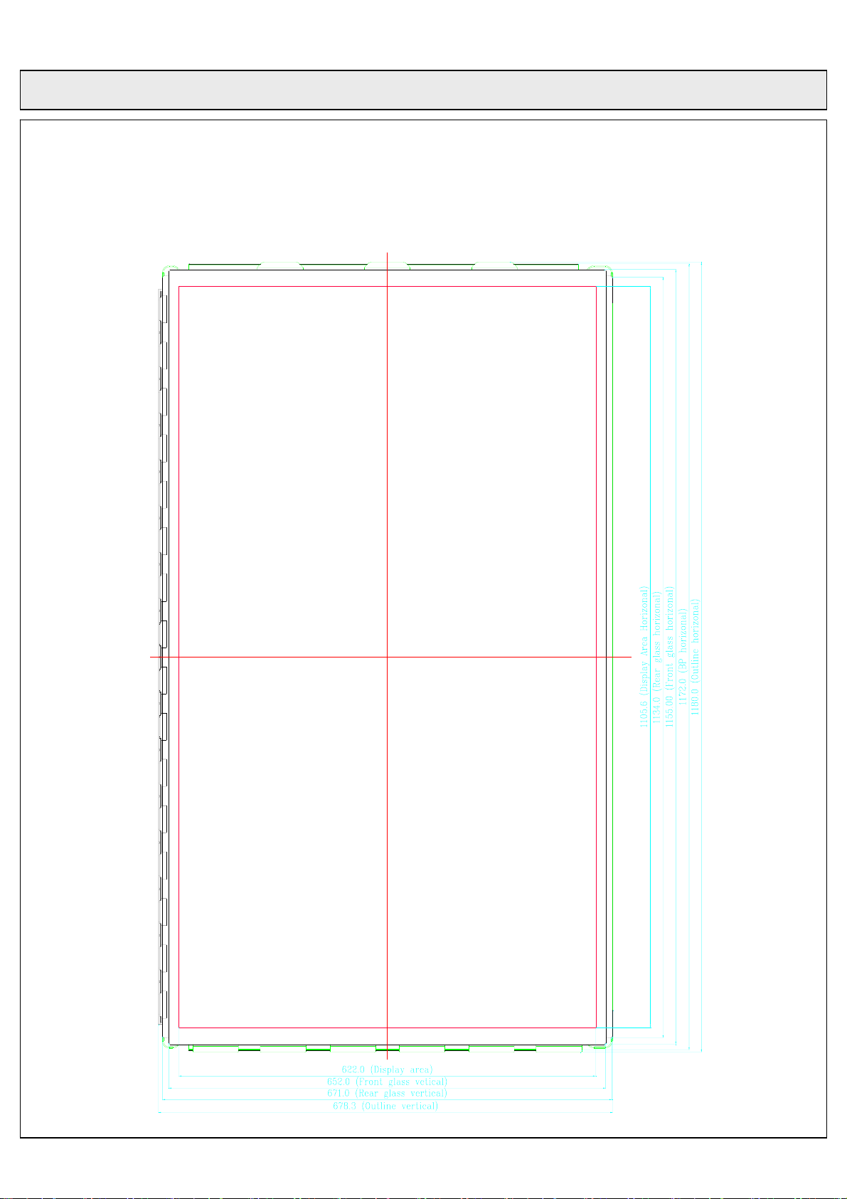
- Display Area : 1105.6(H) × 622.0 (V) ± 0.5mm
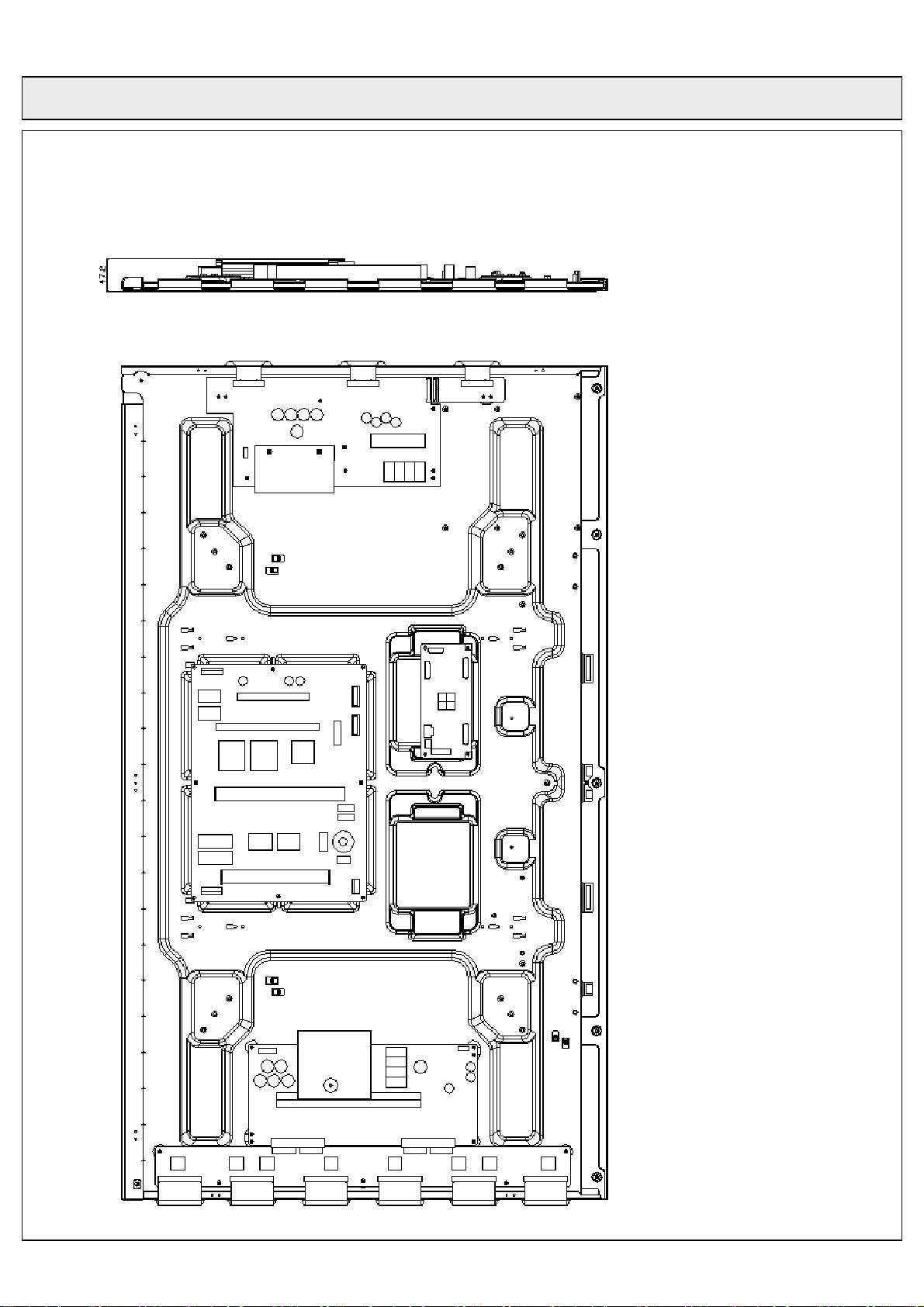
- Outline Dimension : 1180.0(H) × 678.3(V) × 47.2(D) ± 1mm
- Pixel Type : RGB Closed (Well) type
- Number of Gradations : 10bit (R) 1,024 × (G) 1,024 × (B) 1,024 colors (1.073 billion)
: 8bit (R) 256 × (G) 256 × (B) 256 colors (16.78 million)
- Weight : 18-±0.5 Kg (Net 1EA)
- Aspect Ratio : 16:9
- Peak Brightness : Typical 1,800cd/㎡ (1/100 White Window pattern at center)
- Contrast Ratio : Average 180:1 (In a bright room with 100Lux at center)
: Typical 10,000:1 (In a dark room 1/100 White Window pattern at center)
- Power Consumption : Max. 350W (Full-White)
- Expected Life-time : Warranty life time 60,000 Hours with continuous operation
- Display Dot Diagram
nd
nd
2
Pixel
2
Pixel
column
column
3rdPixel
3rdPixel
column
column
...............
...............
Cell Pitch (width)
270㎛
1,365
column
column
Pixel Pitch (width)
Pixel Pitch (width)
1stPixel
1stPixel
column
column
810㎛
Pixel
Pixel
th
th
st
st
1
Pixel
1
Pixel
row
row
2ndPixel
2ndPixel
row
row
3 rdPixel
3 rdPixel
row
row
4 thPixel
4 thPixel
row
row
th
th
768
768
Pixel
Pixel
row
row
Pitch (Height)
R GB
G R B
R GB G R B
R GB G R B
810㎛
R GB G R B
R GB G R B
GB G RB
GB G RB
GB G RB
GB G RB
GB G
GB G RB
...............
...............
...............
...............
GB G RB
...............
...............
GB G RB
...............
...............
GB G RB
...............
...............
...............
...............
GB G
...............
...............
G B G R B
G B G R B
Rev. No. : 0.0 2009. 12. 18. 10/37
Page 11
COC Display Devices Co., Ltd. TENTATIVE No. :
Product Specification of 50HD-PDP Module
2. Electrical Specifications
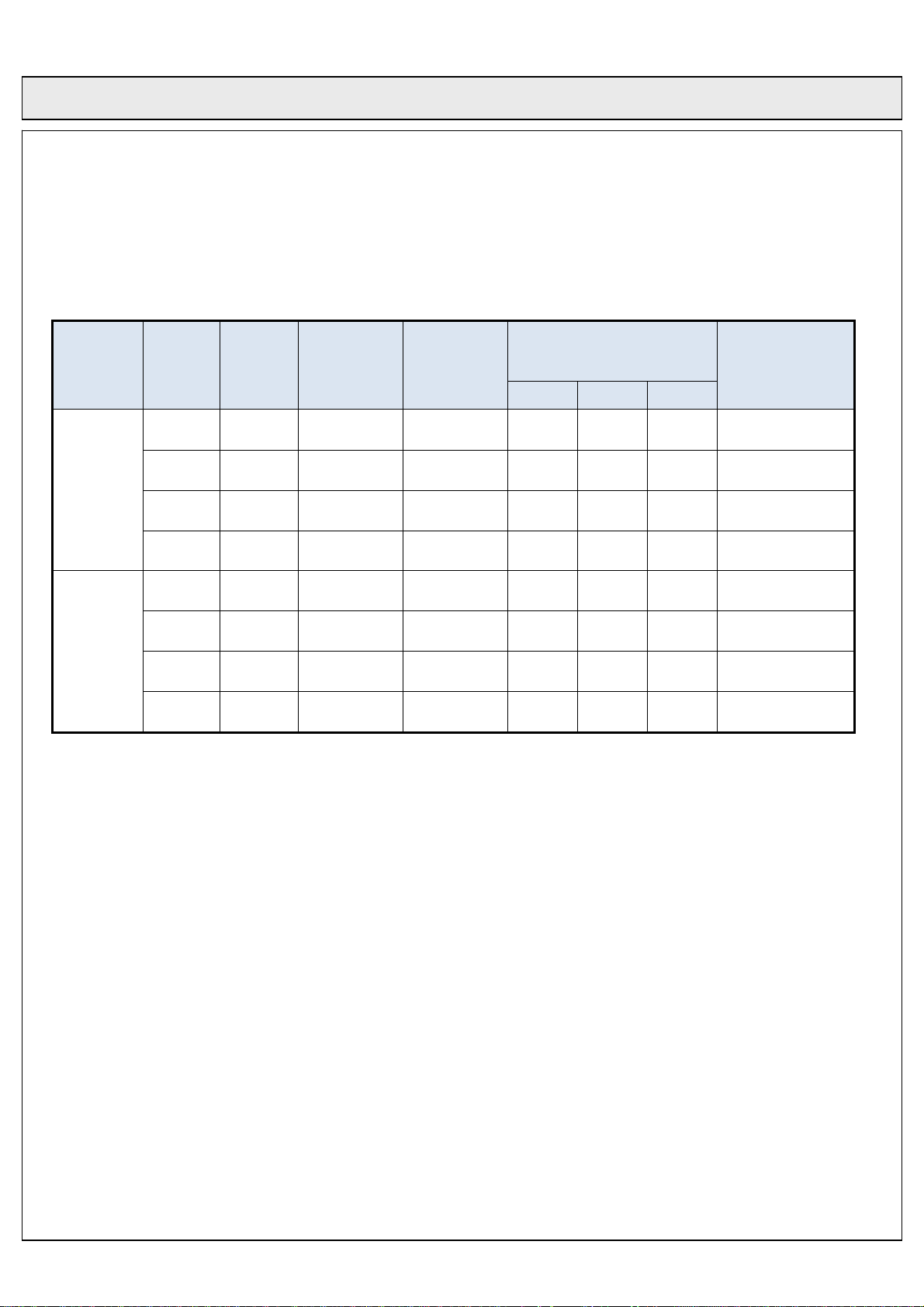
□ Input power Specifications
Output
Typic al
(V)
*1PDP
Module
Output
Name
D5V 5.2 - ±5 0.5 1.0 2.0 120
Vg 15.5 - ±5 0.1 0.3 0.5 200
VA 56 52 ~ 57 ±2 0.01 1.0 1.8 500
Va ri ab le
Voltage
Range(V)
Voltage
Tolerance
(%)
Output Current
(A mean)
Min. Nor. Max.
Ripple & Noise
(mVp-p)
VS 207 200 ~ 210 ±2 0.1 1.4 1.6 700
5V St-by 5.2 - ±5 0.04 1.0 1.8 120
Vsc
Board
(Signal
Interface)
A5V 5.2 - ±5 0.1 2.5 3.5 120
A12V 12 - ±5 0.1 1.0 2.0 160
Vamp 15.5 - ±5 0.1 0.5 2.5 200
*1. PDP Module Maximum Power is below 350W.
[Note]
1. Earth Leakage current
The power supply leakage current shall be less than 0.5mA
Rev. No. : 0.0 2009. 12. 18. 11/37
Page 12
COC Display Devices Co., Ltd. TENTATIVE No. :
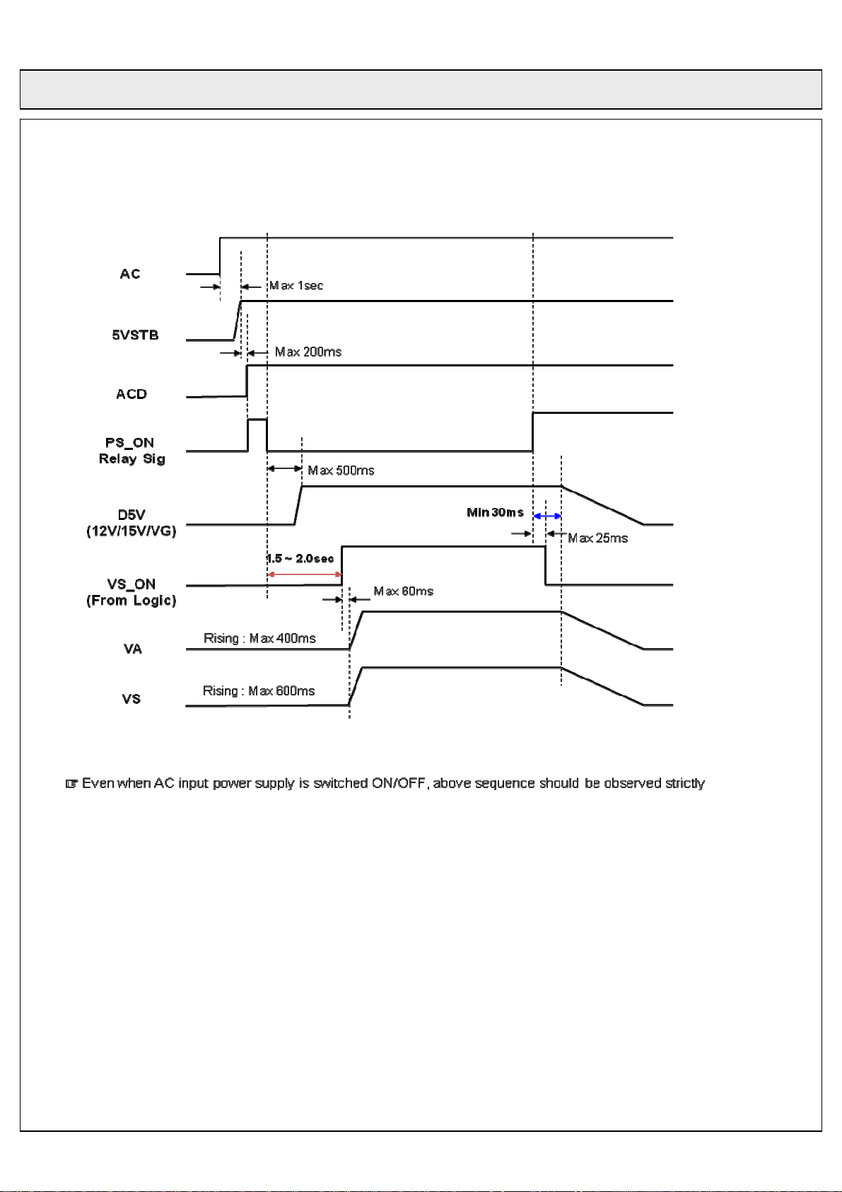
□ Power Sequence
Product Specification of 50HD-PDP Module
Rev. No. : 0.0 2009. 12. 18. 12/37
Page 13
COC Display Devices Co., Ltd. TENTATIVE No. :
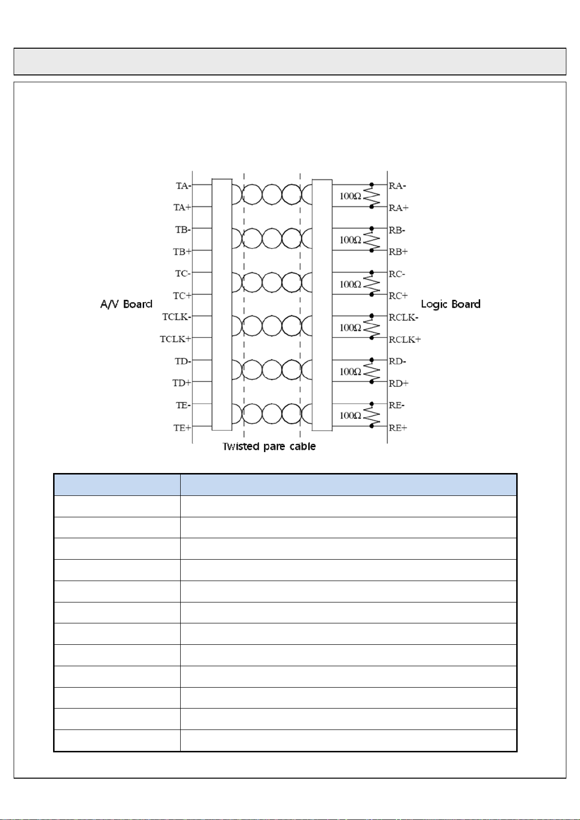
□ LVDS Connection
Product Specification of 50HD-PDP Module
Symbol
RA+ Channel-A Pos. Receiver Input
RA- Channel-A Neg. Receiver Input
RB+ Channel-B Pos. Receiver Input
RB- Channel-B Neg. Receiver Input
RC+ Channel-C Pos. Receiver Input
RC- Channel-C Neg. Receiver Input
RD+ Channel-D Pos. Receiver Input
RD- Channel-D Neg. Receiver Input
RE+ Channel-E Pos. Receiver Input
RE- Channel-E Neg. Receiver Input
RCLK+ Clock Pos. Receiver Input
Function and description
RCLK- Clock Neg. Receiver Input
Rev. No. : 0.0 2009. 12. 18. 13/37
Page 14

COC Display Devices Co., Ltd. TENTATIVE No. :
Product Specification of 50HD-PDP Module
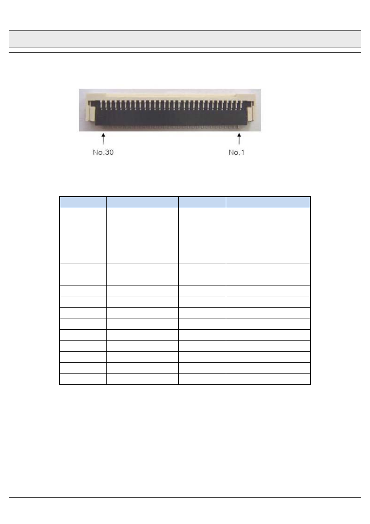
Part_ Number : 1001-65231 (C_NET)
Pin. No Symbol Pin. No Symbol
1 G 17 NC
2 G 18 NC
3 RA- 19 RD-
4 RA+ 20 RD+
5 G 21 G
6 G 22 I2C_Ready
7 RB- 23 RE-
8 RB+ 24 RE+
9 RF- 25 NLNP
10 RF+ 26 G
11 RC- 27 Sclk
12 RC+ 28 G
13 G 29 Sdata
14 G 30 G
15 Rclk- 31 NC
16 Rclk+
※ RF-/+ is 12bit DATA (not used no connect)
Rev. No. : 0.0 2009. 12. 18. 14/37
Page 15
COC Display Devices Co., Ltd. TENTATIVE No. :
Product Specification of 50HD-PDP Module
FFC LVDS connector (Top view)
Pin. No Symbol Pin. No Symbol
1 NC 17 RD-
2 NC 18 RD+
NOTES:
3 RE- 19 G
4 RE+ 20 I2C_Ready
5 RA- 21 G
6 RA- 22 NC
7 G 23 G
8 RB- 24 NC
9 RB+ 25 G
10 G 26 NC
11 RC- 27 NC
12 RC+ 28 SCLK
13 G 29 G
14 Rclk- 30 SDATA
15 Rclk+
16 G
○
1.U2 and U3 connector are all located in Logic Board. Choose one connector only
2.Pin numbering order:
Right to left view from component side of Logic Board
Rev. No. : 0.0 2009. 12. 18. 15/37
Page 16
COC Display Devices Co., Ltd. TENTATIVE No. :
Product Specification of 50HD-PDP Module
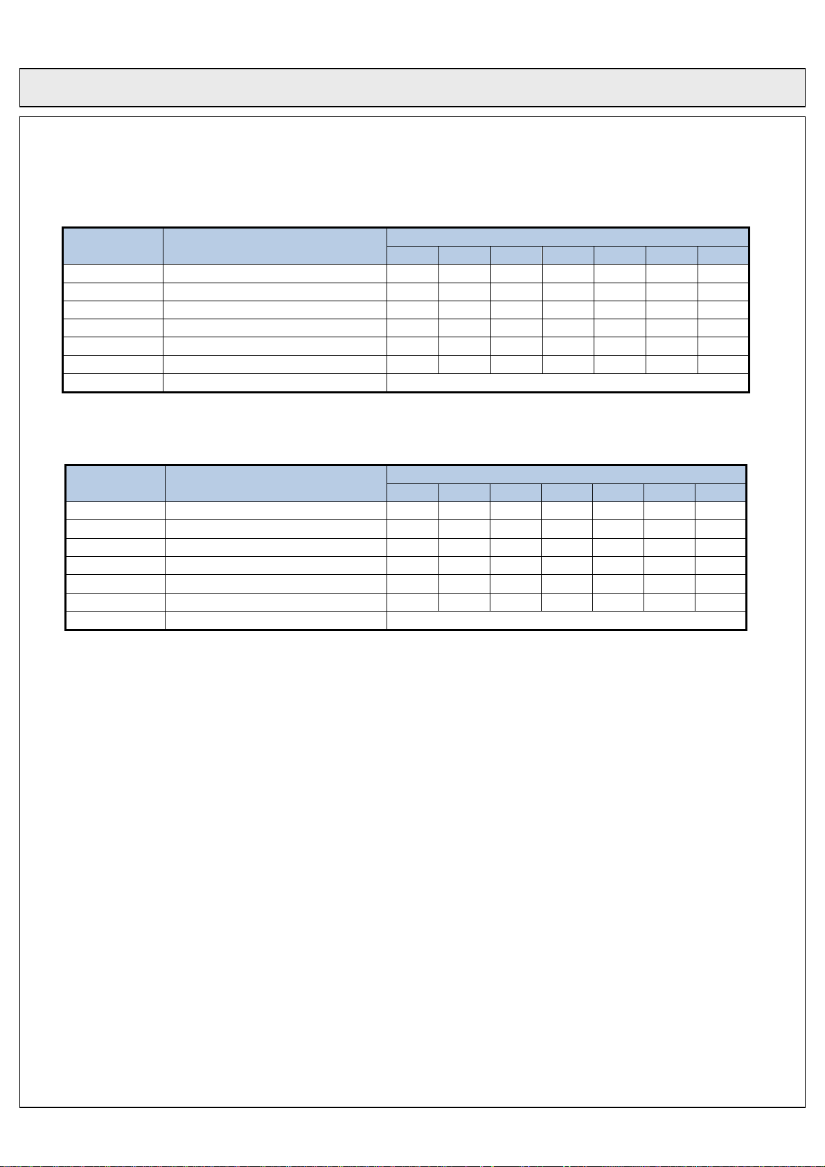
○ LVDS Receiver 8bit
Symbol Signal Definition and Function
RA+/- Channel-A. Receiver Input RE0 RE1 RE2 RE3 RE4 RE5 GE0
RB+/- Channel-B. Receiver Input GE1 GE2 GE3 GE4 GE5 BE0 BE1
RC+/- Channel-C. Receiver Input BE2 BE3 BE4 BE5 HS VS DE
RD+/- Channel-D. Receiver Input RE6 RE7 GE6 GE7 BE6 BE7
RE+/- Channel-E. Receiver Input
RF+/- Channel-F. Receiver Input
RCLK+/- Clock. Receiver Input DCLK
0 1 2 3 4 5 6
LSB ~ MSB
○ LVDS Receiver 10bit
Symbol Signal Definition and Function
RA+/- Channel-A. Receiver Input RE2 RE3 RE4 RE5 RE6 RE7 GE2
RB+/- Channel-B. Receiver Input GE3 GE4 GE5 GE6 GE7 BE2 BE3
RC+/- Channel-C. Receiver Input BE4 BE5 BE6 BE7 HS VS DE
RD+/- Channel-D. Receiver Input RE8 RE9 GE8 GE9 BE8 BE9
RE+/- Channel-E. Receiver Input RE0 RE1 GE0 GE1 BE0 BE1
RF+/- Channel-F. Receiver Input
RCLK+/- Clock. Receiver Input DCLK
0 1 2 3 4 5 6
LSB ~ MSB
NOTE)
RE0~RE9 : 10 bit Red Pixel Video Signal (RE0:LSB, RE10:MSB)
GE0~GE9 : 10 bit Green Pixel Video Signal (GE0:LSB, GE10:MSB)
BE0~BE9 : 10 bit Blue Pixel Video Signal (BE0:LSB, BE10:MSB)
VS : Vertical Video Sync
HS : Horizontal Video Sync
DE : Video Data Enable
Rev. No. : 0.0 2009. 12. 18. 16/37
Page 17
COC Display Devices Co., Ltd. TENTATIVE No. :
Product Specification of 50HD-PDP Module
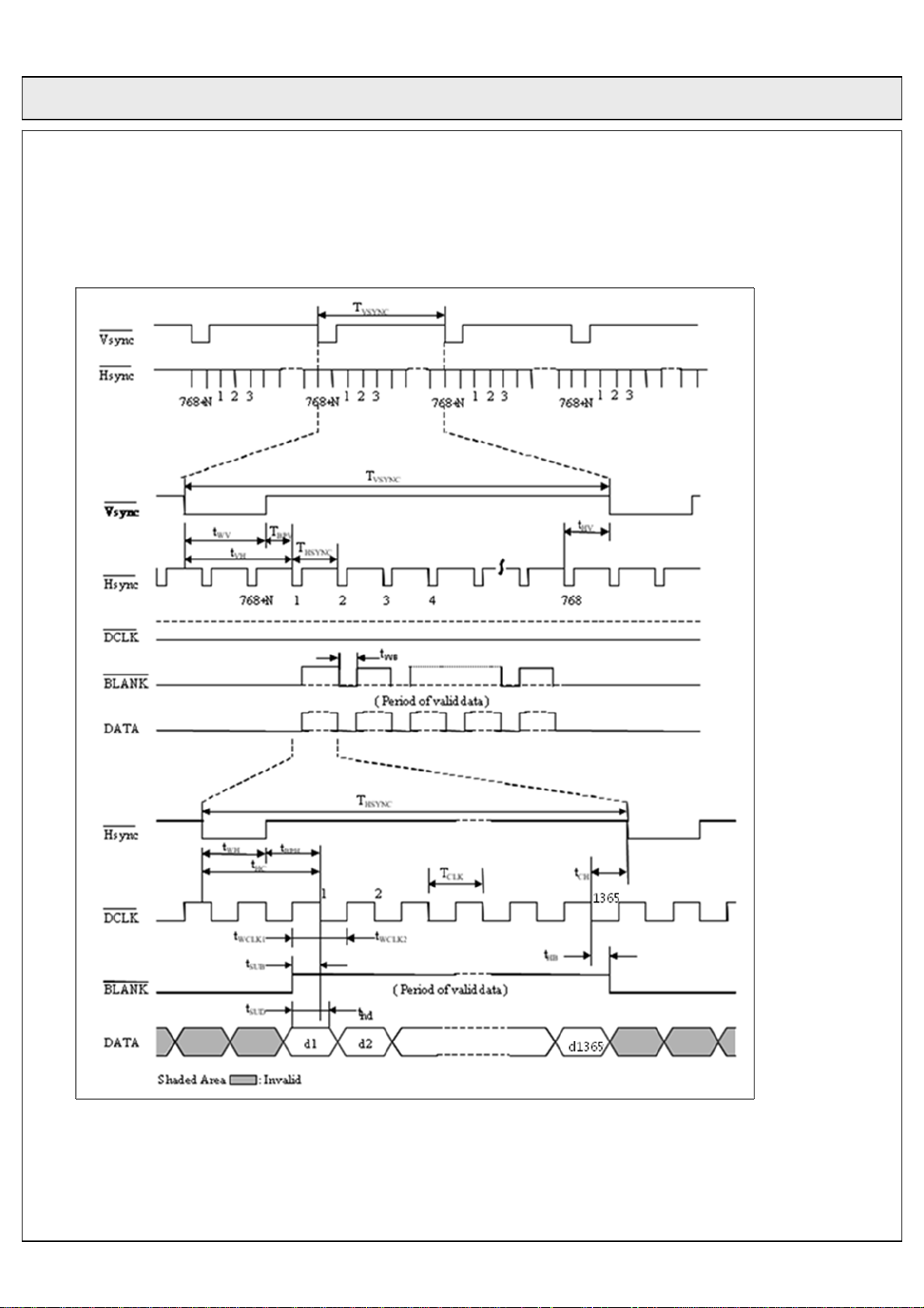
□ Input Signal Timing (Non-interlaced Mode)
Min & max of each signal are measured values when other signal is Typ.
Rev. No. : 0.0 2009. 12. 18. 17/37
Page 18
COC Display Devices Co., Ltd. TENTATIVE No. :
Product Specification of 50HD-PDP Module
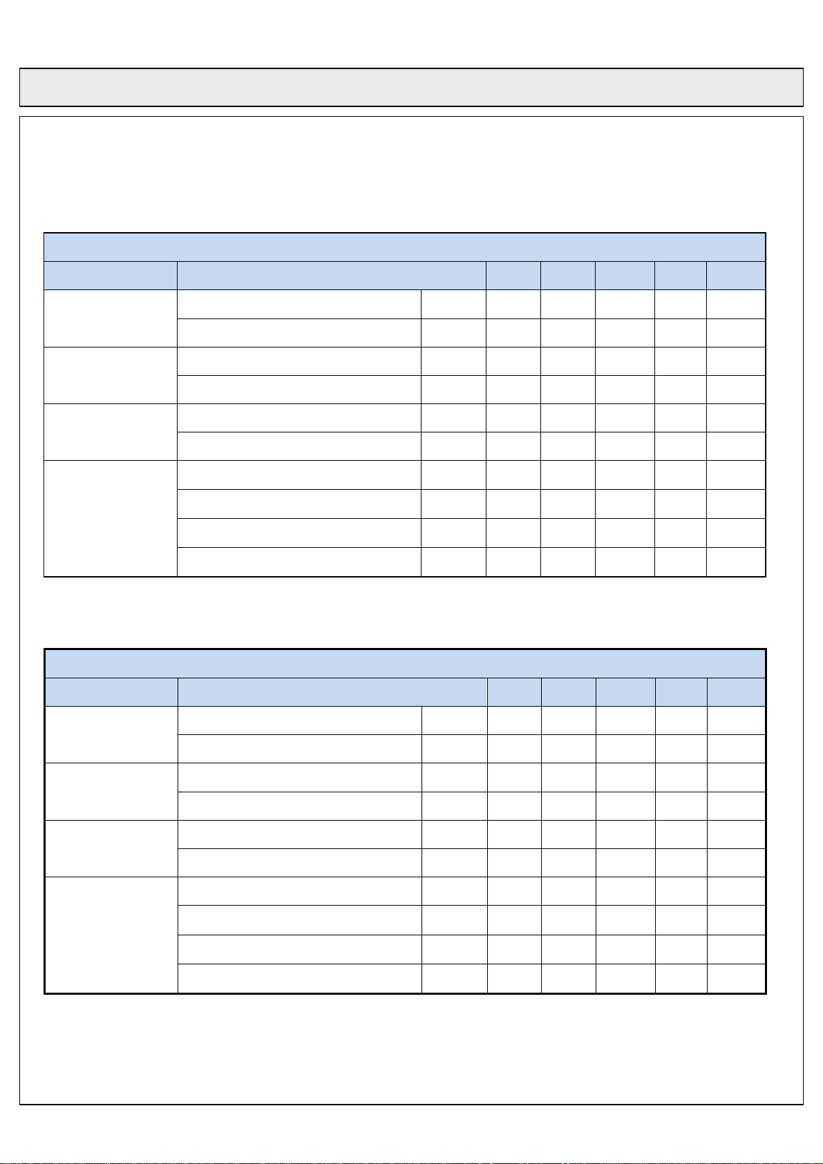
○ Input signal 60Hz specification
60Hz
Parameter Symbol Min. Typ. Max. Unit Note
Period Tclk 14.3 13.5 12.8 ns
DCLK
Frequency - 71 74 77 MHz
Period Thp 1451 1504 1520 Tclk
Hsync
Width Twh 6 10 12 Tclk
Period Tvp 810 820 830 Thp
Vsync
Width Twv 2 6 10 Thp
Horizontal Valid T hv 1365 1365 1365 Tclk
Data
Enable
○ Input signal 50Hz specification
Parameter Symbol Min. Typ. Max. Unit Note
DCLK
Hsync
Vsync
Horizontal Back Porch T hbp 56 76 86 Tclk
Vertical Valid Tvp 768 768 768 Thp
Vertical Back Porch Tvbp 20 30 35 Thp
50Hz
Period Tclk 14.3 13.5 12.8 ns
Frequency - 71 74 77 MHz
Period Thp 1451 1504 1520 Tclk
Width Twh 6 10 12 Tclk
Period Tvp 976 984 993 Thp
Width Twv 2 6 10 Thp
Horizontal Valid T hv 1365 1365 1365 Tclk
Data
Enable
Horizontal Back Porch T hbp 56 76 86 Tclk
Vertical Valid Tvp 768 768 768 Thp
Vertical Back Porch Tvbp 20 30 35 Thp
Rev. No. : 0.0 2009. 12. 18. 18/37
Page 19
COC Display Devices Co., Ltd. TENTATIVE No. :
Product Specification of 50HD-PDP Module
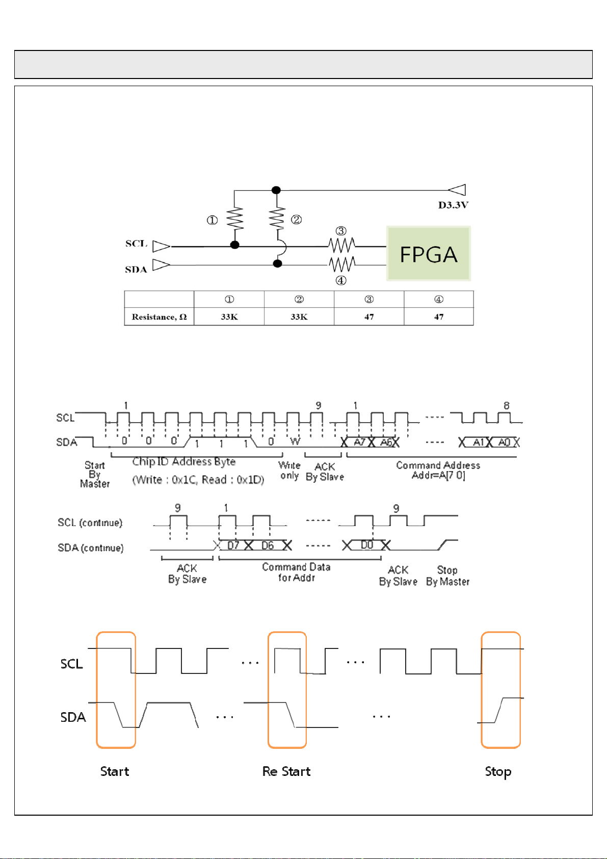
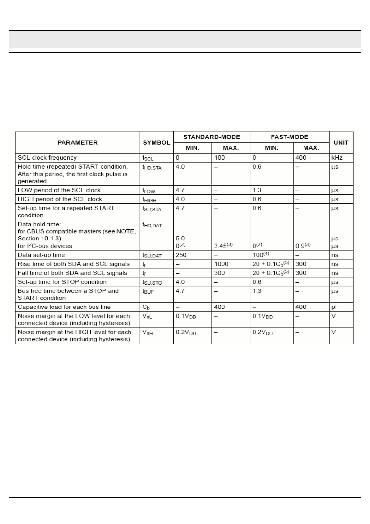
□ I2C Timing Specification & Register Description
○ I2C Start, Restart and Stop condition
Rev. No. : 0.0 2009. 12. 18. 19/37
Page 20
COC Display Devices Co., Ltd. TENTATIVE No. :
Product Specification of 50HD-PDP Module
Rev. No. : 0.0 2009. 12. 18. 20/37
Page 21
COC Display Devices Co., Ltd. TENTATIVE No. :
Product Specification of 50HD-PDP Module
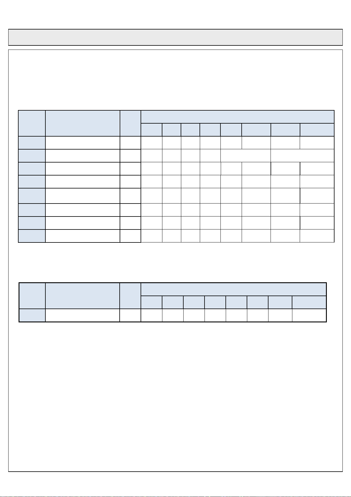
○ Register Description
I2C
address
01h SYNC_MODE 3bit N N N N N TBD AUTO MANUAL
08h BRIGHT_MODE 4bit N N N N PAL (1:0) NT (1:0)
10h COLOR_INVERSION 1bit N N N N N N N ON/OFF
18h ISM_MODE 1bit N N N N N N N ON/OFF
20h PGR 3bit N N N N N ON/OFF
Mode Bit
7 6 5 4 3 2 1 0
I2C data
SEL
(1:0)
B1h APL Read Request 1bit N N N N N N N ON/OFF
B2h APL value MSB 1bit N N N N N N N 8bit
B3h APL value LSB 8bit 7bit 6bit 5bit 4bit 3bit 2bit 1bit 0bit
○ Sync MODE
I2C
address
01h SYNC_MODE 3bit N N N N N TBD AUTO MANUAL
Chip_id: PDP chip Version (TBD)
Sync_auto: Sync automatic/manual mode selection (1 : Auto, 0 : Manual)
Sync_Manual: Frequency selection manual mode
Default setting: Automatic
Mode Bit
7 6 5 4 3 2 1 0
I2C data
Rev. No. : 0.0 2009. 12. 18. 21/37
Page 22
COC Display Devices Co., Ltd. TENTATIVE No. :
Product Specification of 50HD-PDP Module
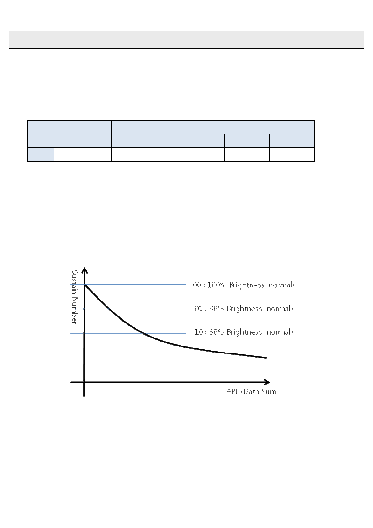
○ Bright MODE
I2C
address
08h BRIGHT_MODE 4bit N N N N PAL (1:0) NT (1:0)
PAL(1:0) : 50Hz bright mode
NT(1:0) : 60Hz bright mode
“00” : 100% brightness mode(Default Value)
“01” : 80% brightness mode
Mode Bit
7 6 5 4 3 2 1 0
I2C data
“10” : 60% brightness mode
“11” : TBD
Rev. No. : 0.0 2009. 12. 18. 22/37
Page 23
COC Display Devices Co., Ltd. TENTATIVE No. :
Product Specification of 50HD-PDP Module
○ Color Inversion MODE
I2C
address
10h COLOR_INVERSION 1bit N N N N N N N ON/OFF
Image inversion enable
“0” : Image inversion off, Default Value
“1” : Image inversion on
Mode Bit
7 6 5 4 3 2 1 0
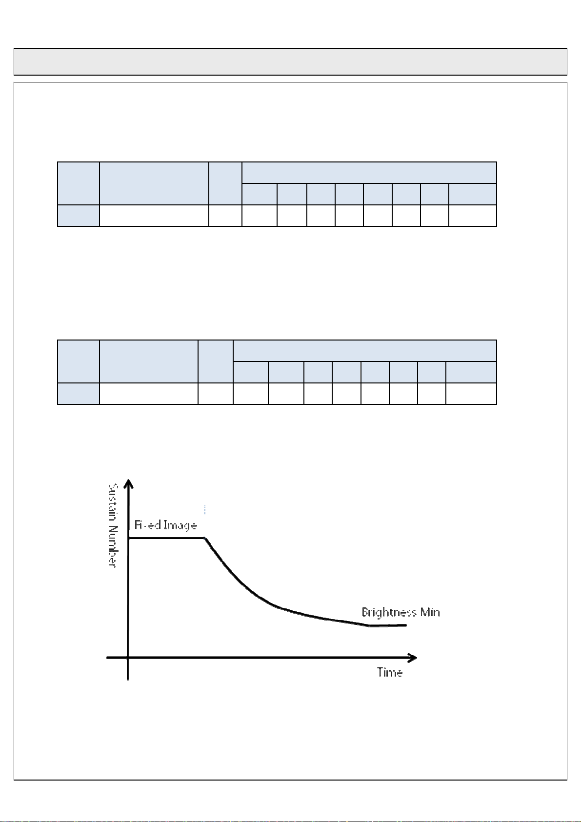
○ IRR (Image Retention Reduction) MODE
I2C data
I2C
address
18h IRR_MODE 1bit N N N N N N N ON/OFF
This module has been equipped with a special method that minimizes the image retention phenomenon.
When in the fixed pattern display mode decreases the brightness over a period of 5 sec with small steps.
The figure below shows that the decrease in brightness is so small the user will not notice.
Mode Bit
7 6 5 4 3 2 1 0
I2C data
The Brightness level decreases 1 step per 3sec to Brightness min level.
“1”: Image Retention Reduction on, Default Value.
“0”: Image Retention Reduction off.
Rev. No. : 0.0 2009. 12. 18. 23/37
Page 24
COC Display Devices Co., Ltd. TENTATIVE No. :
Product Specification of 50HD-PDP Module
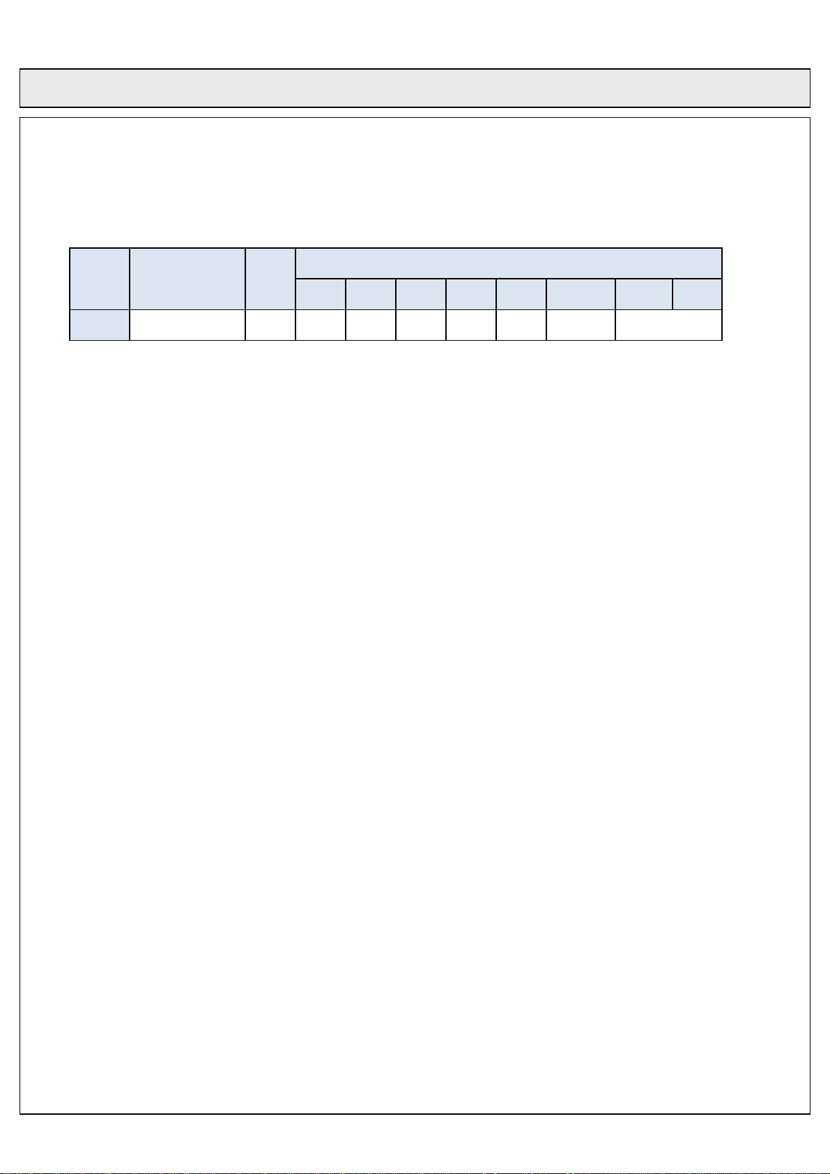
○ Internal Pattern Generation
I2C
address
20h PGR 3bit N N N N N ON/OFF SEL (1:0)
Pattern generation is automatically.
ON/OFF: “0” => OFF, “1” => ON Default Value “0”
SEL(1:0): Pattern Select
“01”: rotation stop
“10”: color bar
Mode Bit
7 6 5 4 3 2 1 0
I2C data
“00”: H character
“11”: rotation pattern
1.F_W Æ 2.F_R Æ 3.F_G Æ 4.F_B Æ
5.Horigental 256 gray_White Æ
6.Horigental 256 gray_Red Æ
7.Horigental 256 gray_Green Æ
8.Horigental 256 gray_Blue Æ
9.Vertical 256 gray_White Æ
10.Vertical 256 gray_Red Æ
11.Vertical 256 gray_Green Æ
12.Vertical 256 gray_Blue Æ
13.Diagonal 256 gray_White Æ
14. Diagonal 256 gray_Red Æ
15. Diagonal 256 gray_Green Æ
16. Diagonal 256 gray_Blue Æ 1.Full_White
Rev. No. : 0.0 2009. 12. 18. 24/37
Page 25
COC Display Devices Co., Ltd. TENTATIVE No. :
Product Specification of 50HD-PDP Module
3. ELECTRO OPTICAL SPECIFICATIONS
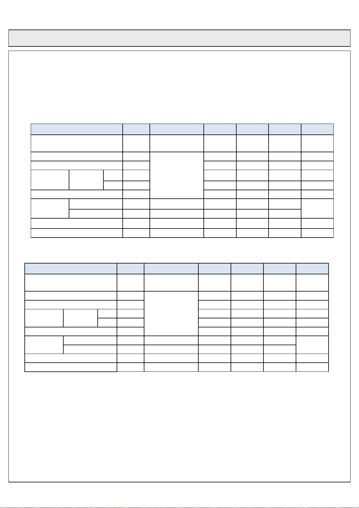
□ Electro Optical characteristic Specifications (60Hz)
ITEM Symbol Condition 1) Min. Typ. Max. Unit
Peak White Brightness*
Average White Brightness* BW
Brightness Uniformity BU
Color
Coordinate
Color Coordinate Uniformity CU -0.01 0 +0.01
Contrast
Ratio*
Power Consumption 4) PW Full White - 280 300 W
White
Bright Room CRBR 100Lx at center 140:1 180:1 -
Dark Room 3) CRDR 1% white window 8,000:1 10,000:1 -
Tsync Margin Hz +/-1.5 Hz
X
Y YW 0.280 0.295 0.310
BWP
XW
1% white window
(Test mode)
Full White
1500 1800 -
155 170 - cd/m
-10 0 +10 %
0.270 0.285 0.300
2
cd/m
Contrast
Ratio*
2)
2
□ Electro Optical characteristic Specifications (50Hz)
ITEM Symbol Condition 1) Min. Typ. Max. Unit
Peak White Brightness*
Average White Brightness* BW
Brightness Uniformity BU
Color
Coordinate
Color Coordinate Uniformity CU -0.01 0 +0.01 0
Contrast
Ratio*
Power Consumption 4) PW Full White - 280 300 W
White
Bright Room CRBR 100Lx at center 130:1 170:1 -
Dark Room 3) CRDR 1% white window 8,000:1 10,000:1 -
Tsync Margin Hz +0.7/-1.3 Hz
X
Y YW 0.280 0.295 0.310
BWP
XW
1% white window
(Test mode)
Full White
*) Module brightness can be lowed up to 25% comparing with room temperature when panel temperature is below
than 18 .℃
1) All characteristics are measured in the room temperature.
2) The brightness of the white peak position is measured while the 1%-window pattern is “ON” state. And then, it
should be checked in 10 seconds after 1%-window is “ON” state.
- Occasionally, the dark position could be changed to any other point arbitrary.
3) The brightness of dark room is less than 1 lux.
4) Total Power Consumption can be up to 350W according to the displayed pattern.
1300 1500 -
155 170 - cd/m
-10 0 +10 %
0.270 0.285 0.300
2
cd/m
Contrast
Ratio*
2)
2
Rev. No. : 0.0 2009. 12. 18. 25/37
Page 26
COC Display Devices Co., Ltd. TENTATIVE No. :
Product Specification of 50HD-PDP Module
4. MECHANICAL AND ENVIRONMENTAL SPECIFICATIONS
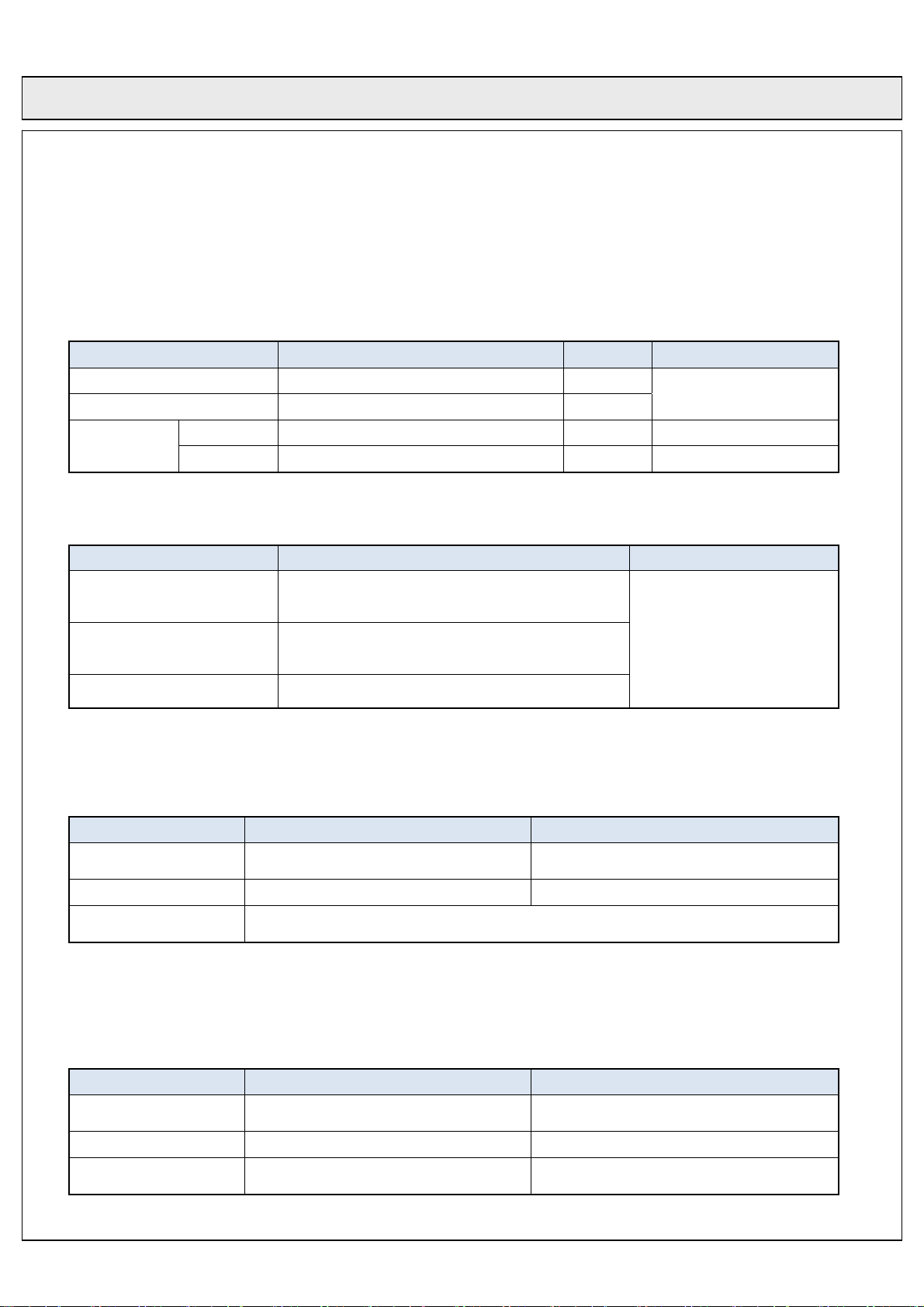
□ Mechanical Characteristic Specifications
Item Spec. Unit Remark
Outline Dimensions 1180.0(H)*678.3(V)*47±1 mm
Display Area 1105.6(H)*622.0(V)*±0.5 mm
Weight
□ Vibration, shock and Drop Specifications
Vibration
Shock
Drop
□ Environmental Conditions
Ambient
Temperature
Humidity
Panel surface
temperature
Note : 1. this module can be operated normally at lower altitude than 2000m(625Torr)
It has be operated after for at least 15 minutes.
Ambient
Temperature
Humidity 20~80% RH 5~85% RH
Air Pressure
Net 18±0.5 Kg
Gross 268.0±5(10EA/1BOX) Kg
Item Condition Remark
▶X,Y direction 1.04G, Z direction, 0.73G, 2~200Hz
(Sweep time : 30 Min)
▶X,Y direction 20G, Z direction 15G, duration time
20ms
▶Bottom : Free Falling : 20 cm
1) Operation Condition
Item Recommended Absolute maximum
5℃~45℃ 0℃~50℃
20~70% RH 20~80% RH
Absolute maximum temperature: 120℃ ( ∆T ≤ 20℃/㎝)
2. In case that a module is left out at the low temperature for a long time(more than 1 hour),
2) Storage Conditions
Item Recommended Absolute maximum
-5℃~45℃ -20℃~70℃
633Torr~760Torr
(0~1,500m)
▶ Non operation
▶ 10ea Packed state
229Torr~760Torr
(0~10,000m)
See” Outline Drawing”
Rev. No. : 0.0 2009. 12. 18. 26/37
Page 27

COC Display Devices Co., Ltd. TENTATIVE No. :
Product Specification of 50HD-PDP Module
5. Image Sticking Characteristics
□
Image Sticking
The fluorescent substance used in the plasma module loses its brightness with the lapse of
lighting time. This deterioration in brightness appears to be a difference in brightness in
relation to the surroundings, and comes to be recognized as image sticking.
In other words, the image sticking is defined as follows: when the same pattern
(of the fixed display) is displayed for a long time, a difference in brightness is caused around
the lighting area and non-lighting area due to deterioration in the fluorescent substance.
When the present pattern is changed over to another one, the boundary comes to be seen
between the lighting area and non-lighting area due to difference in brightness in the pattern
shown shortly before changeover.
If this conditions is accumulated, the boundary or image sticking comes to be seen with the naked eyes.
□ Warranty
Image sticking and faults in brightness and picture elements are excluded from the warranty objects.
Proposed measures taken to relieve image sticking
So long as there is the reduction of brightness in the fluorescent substance, it is impossible to avoid the
occurrence of image sticking. Therefore, to relieve image sticking, we offer you a method of entering an image
input that may ensure reluctance to the generation of the difference in brightness reduction among the displayed dots.
The images from TV broadcasting involve a high rate of motion picture displays.
Therefore, there is less chance of being a cause of difference in brightness reduction among the cells.
Even when the fixed patterns are displayed, they generally last for a few minutes.
Since the same pattern is less liable to be displayed, there is almost no influence toward image sticking.
If the fixed patterns tend to be displayed for a long time, however,
there occurs a substantial imbalance between the lighting and non-lighting areas,
thus causing a difference in brightness as a result. In this document,
we offer you some proposals of installation, paying attentions to the two points: the reduction of difference
in brightness achieved by integrated lighting time leveling and the method of edge smearing to make image
sticking hard to be discerned.
The result from these proposals can, however, greatly depend on the contents of images and the
operating environment.
Therefore, we consider that it is essential to take the suitable measures in consideration of the customer’s
operating environment.
Example of Proposal 1: The display position is moved while the fixed display pattern is changed over,
or it is scrolled during the display.
Example of Proposal 2: If possible, a pattern of complementary color is incorporated
(for integrated time leveling).
Example of Proposal 3: The fixed pattern and the motion picture display are reciprocally exchanged,
in order to minimize display period of the fixed pattern.
Example of Proposal 4: During operation, the brightness of screen is suppressed as low as possible.
For the display patterns, characters are indicated not on the black ground (non-picture area)
but on the colored ground (mixture of R, G, B recommended).
Rev. No. : 0.0 2009. 12. 18. 27/37
Page 28
COC Display Devices Co., Ltd. TENTATIVE No. :
6. OUTLINE DRAWING
□ Front View
Product Specification of 50HD-PDP Module
Rev. No. : 0.0 2009. 12. 18. 28/37
Page 29
COC Display Devices Co., Ltd. TENTATIVE No. :
Product Specification of 50HD-PDP Module
□ Rear View
Rev. No. : 0.0 2009. 12. 18. 29/37
Page 30
COC Display Devices Co., Ltd. TENTATIVE No. :
Product Specification of 50HD-PDP Module
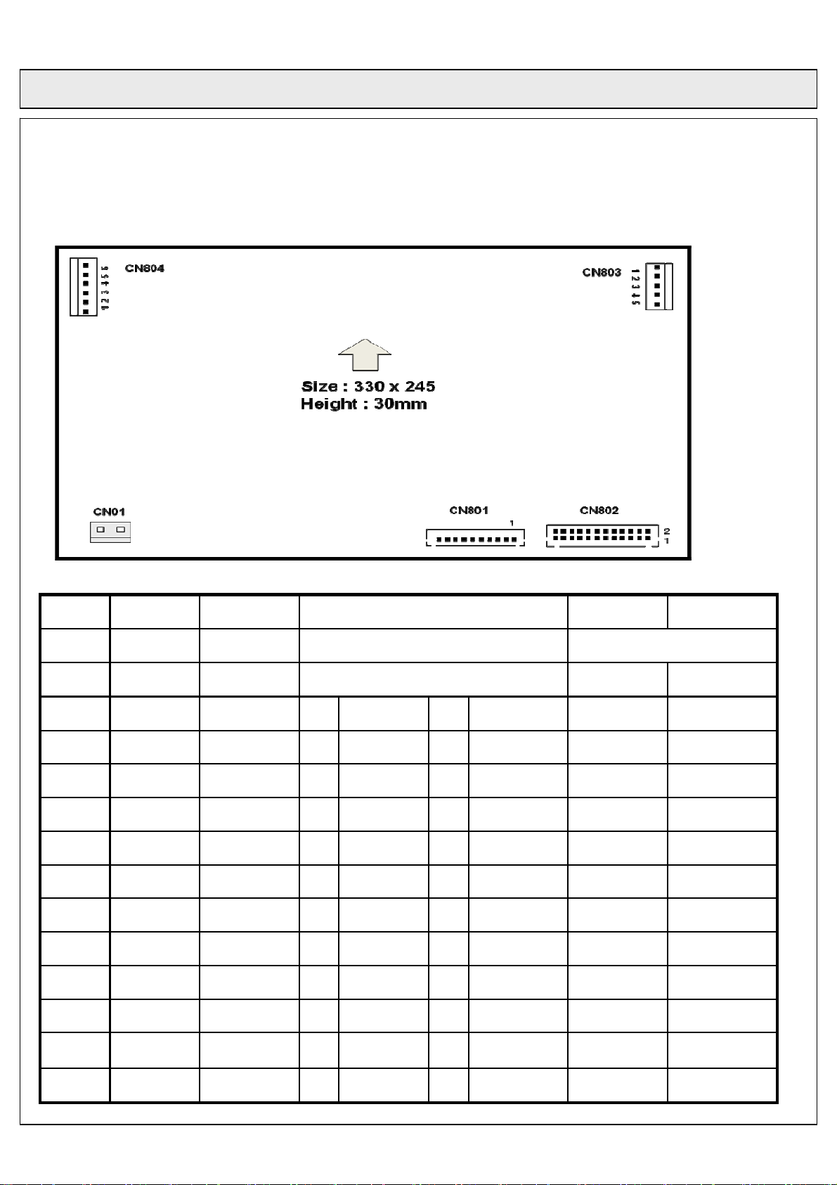
7. Connector and Connections
Location CN01 CN801 CN802 CN803 CN804
Usage From AC To Logic PSU ~ AV Interface To X/Y Board
Pin No. Pin Name Pin Name Pin Name Pin Name Pin Name
1 Live D5V 1 PS_ON 2 VS_ON VS VS
2 NC D5V 3 5VTB 4 GND_5VSTB VS VS
3 Neutral GND 5 GND_Vamp 6 GND_Vamp GND GND
4 -- GND 7 Vamp 8 Vamp GND VA
5 -- D5V 9 GND_A5V 10 GND_A5VV Vg GND
6 -- GND 11 GND_A5V 12 GND_A5VV -- Vg
7 -- RLY_SYG 13 A5V 14 A5V -- --
8 -- ACD 15 A5V 16 A5V -- --
9 -- VS_ON 17 GND_A12V 18 GND_A12V -- --
10 -- NC 19 A12V 20 GND_A12V -- --
11 -- -- 21 A12V 22 A12V -- --
12 -- -- 23 ACD 24 NC -- --
Rev. No. : 0.0 2009. 12. 18. 30/37
Page 31
COC Display Devices Co., Ltd. TENTATIVE No. :
Product Specification of 50HD-PDP Module
8. LABEL
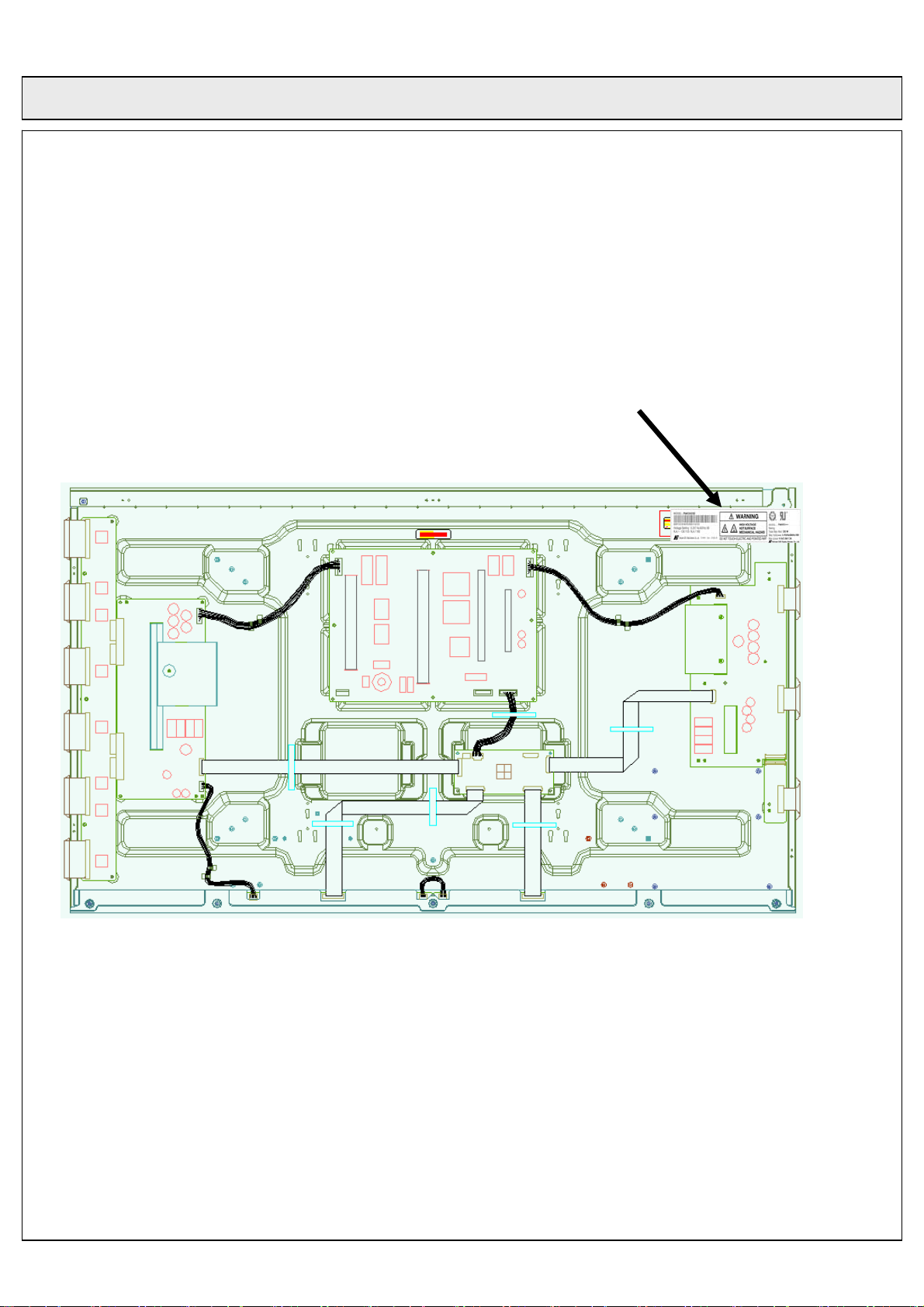
□ LABEL Sticking Position: Product Label ( 150*27 mm )
Rev. No. : 0.0 2009. 12. 18. 31/37
Page 32
COC Display Devices Co., Ltd. TENTATIVE No. :
Product Specification of 50HD-PDP Module
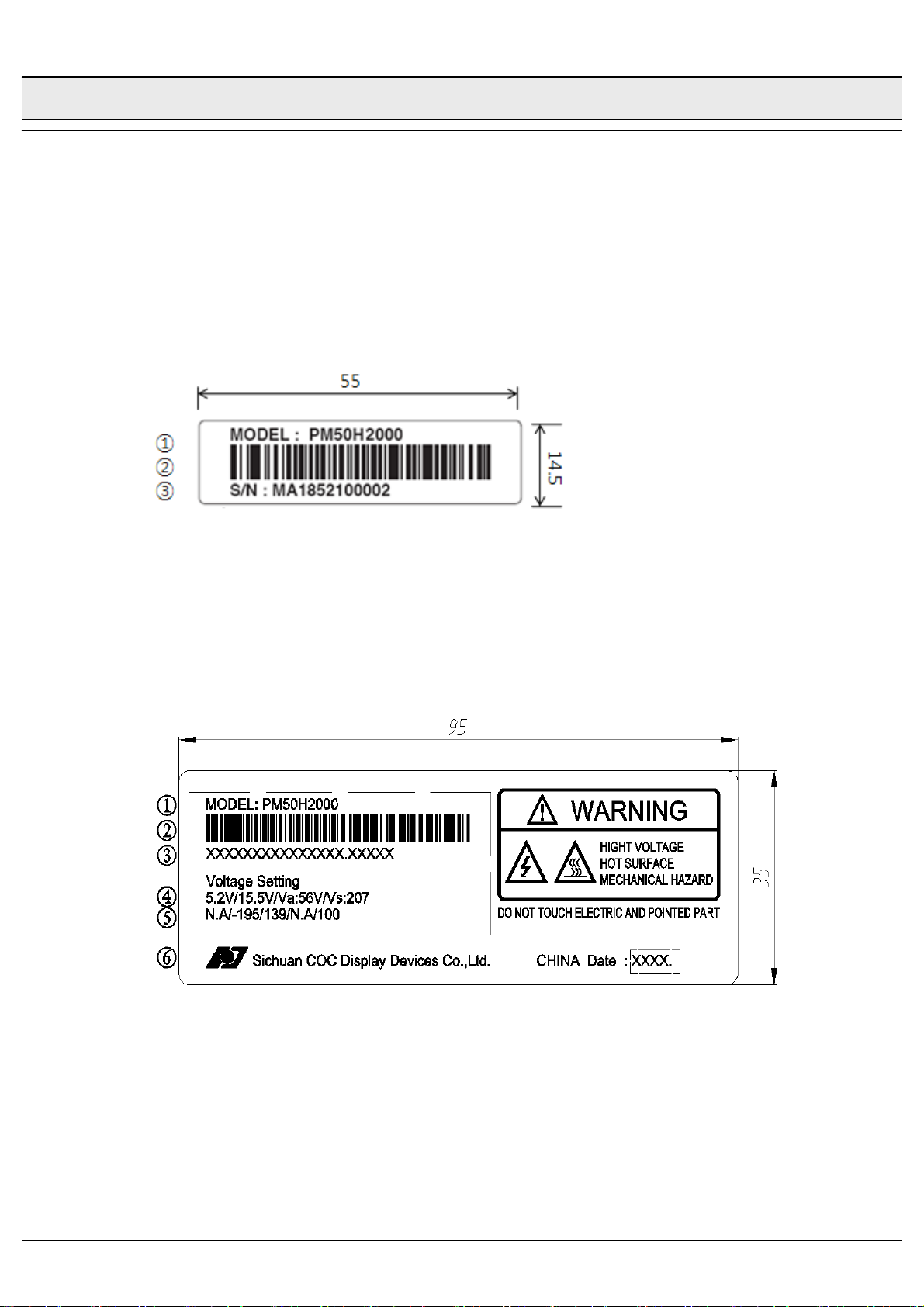
□ LABEL
1) LABEL-1 ; Identification Label
① Model Name
② Bar Code (Code 128, Contains the manufacture No.)
③ Serial Number
2) LABEL-2 ; Voltage and Warning Label
① Model Name
② Bar Code
③ Manufacture No.
④ Adjusting voltage : (DC, Va, Vs)
⑤ Adjusting voltage : (Setup/-Vy/Vsc/Ve/Vzb)
⑥ The Trade Name of COC Display Devices.
Rev. No. : 0.0 2009. 12. 18. 32/37
Page 33
COC Display Devices Co., Ltd. TENTATIVE No. :
Product Specification of 50HD-PDP Module
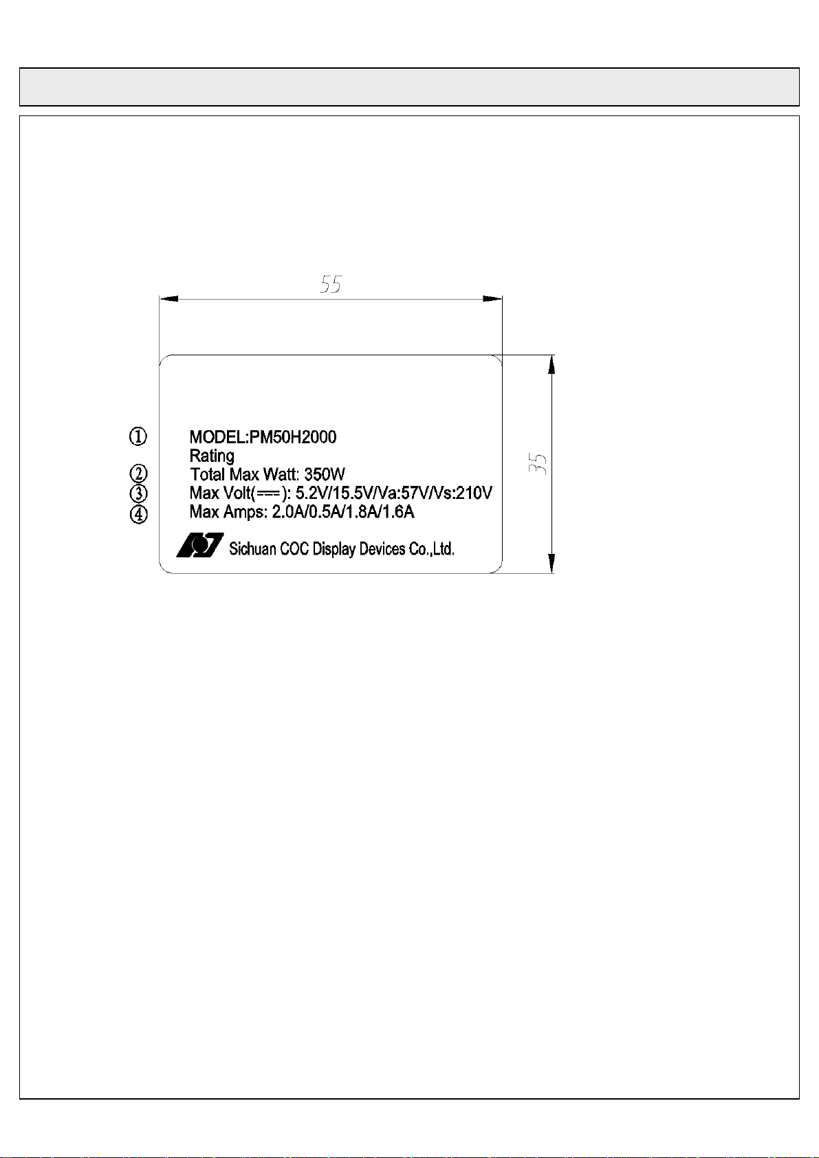
3) LABEL-3 ; Safety approval Label
① Model Name
② Max Watt.
③ Max Volts.
④ Max Amps
Rev. No. : 0.0 2009. 12. 18. 33/37
Page 34
COC Display Devices Co., Ltd. TENTATIVE No. :
Product Specification of 50HD-PDP Module
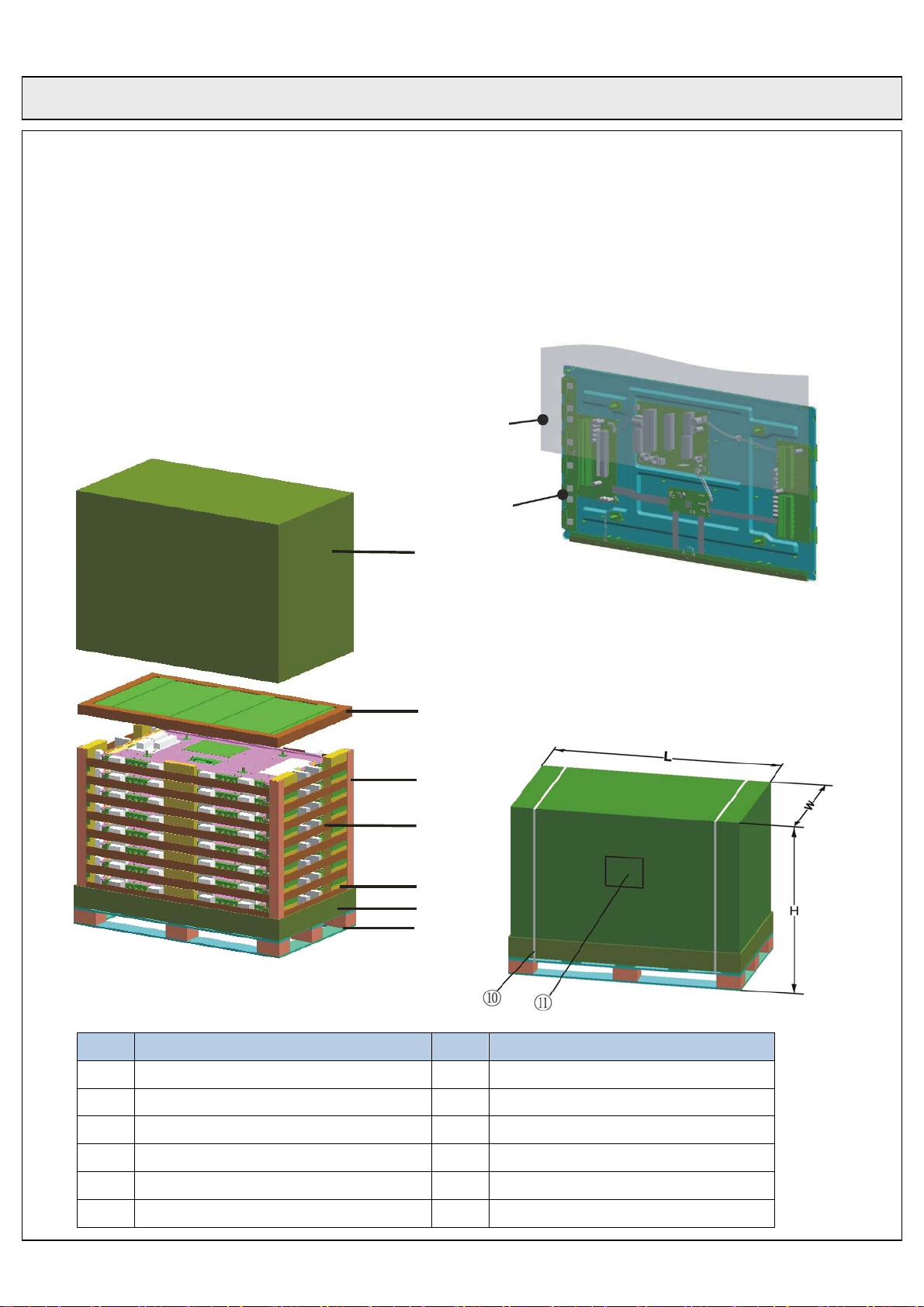
9. PACKING
□ Box Packing (8 module per each box) – A short distance movement.
□ Packing dimensions (L*W*H) : 1420 x 840 x 1050 mm)(Including Pallet)
□ Weight : About 222±5 Kg
□ Packing Assembly
①
⑧
⑨
②
③
④
⑤
⑥
⑦
NO. 항 목 NO. 항 목
1 PACKING BOX 7 PALLET
2 PACKING PAD-TOP 8 PACKING VYNYL
3 PACKING PAPER LINER 9 PDP MODULE
4 PACKING PAD-MIDDLE 10 PP-BAND
5 PACKING PAD-DOWN 11 LABEL-INSPECTION
6 PACKING BOX BOTTOM
Rev. No. : 0.0 2009. 12. 18. 34/37
Page 35
COC Display Devices Co., Ltd. TENTATIVE No. :
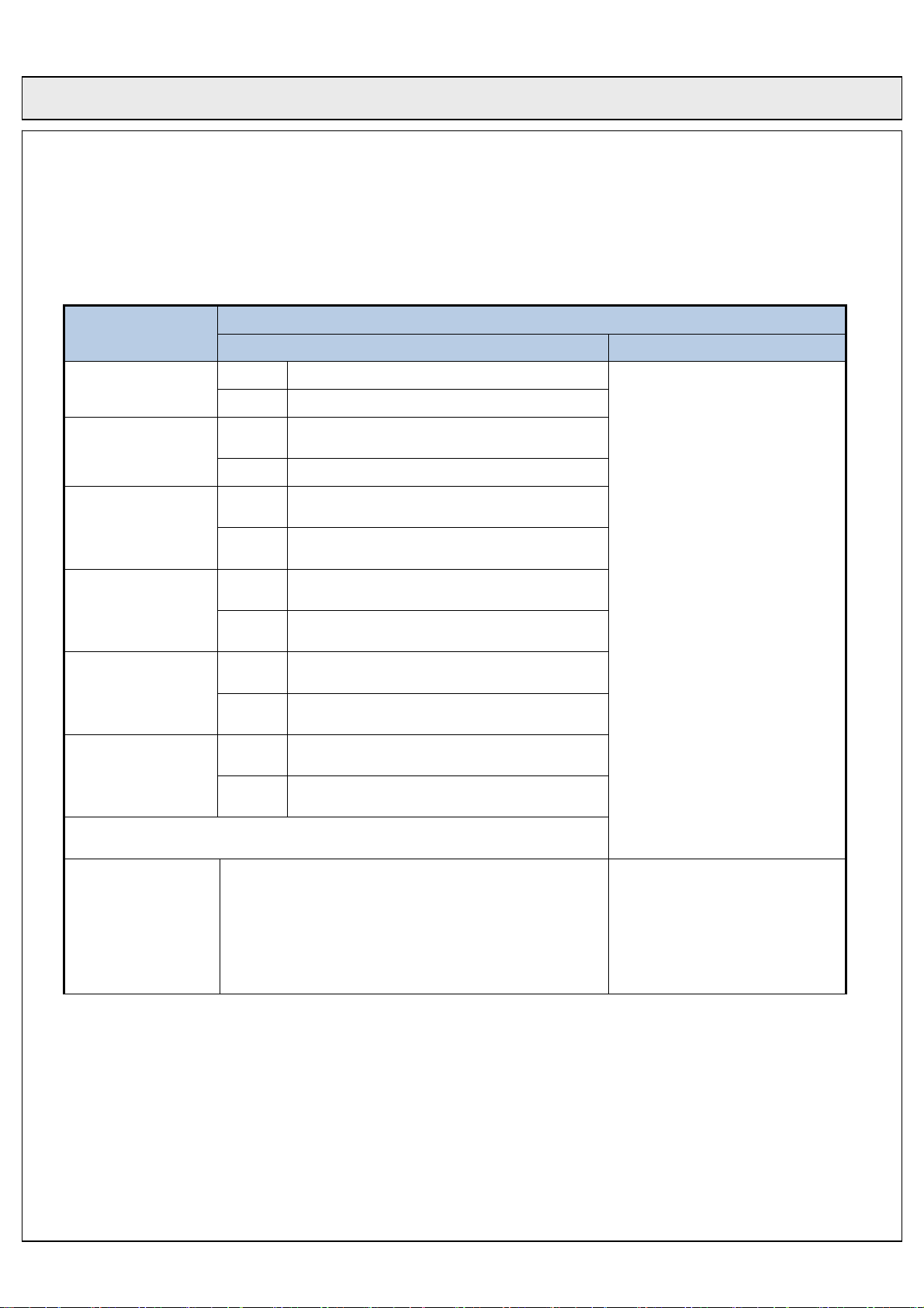
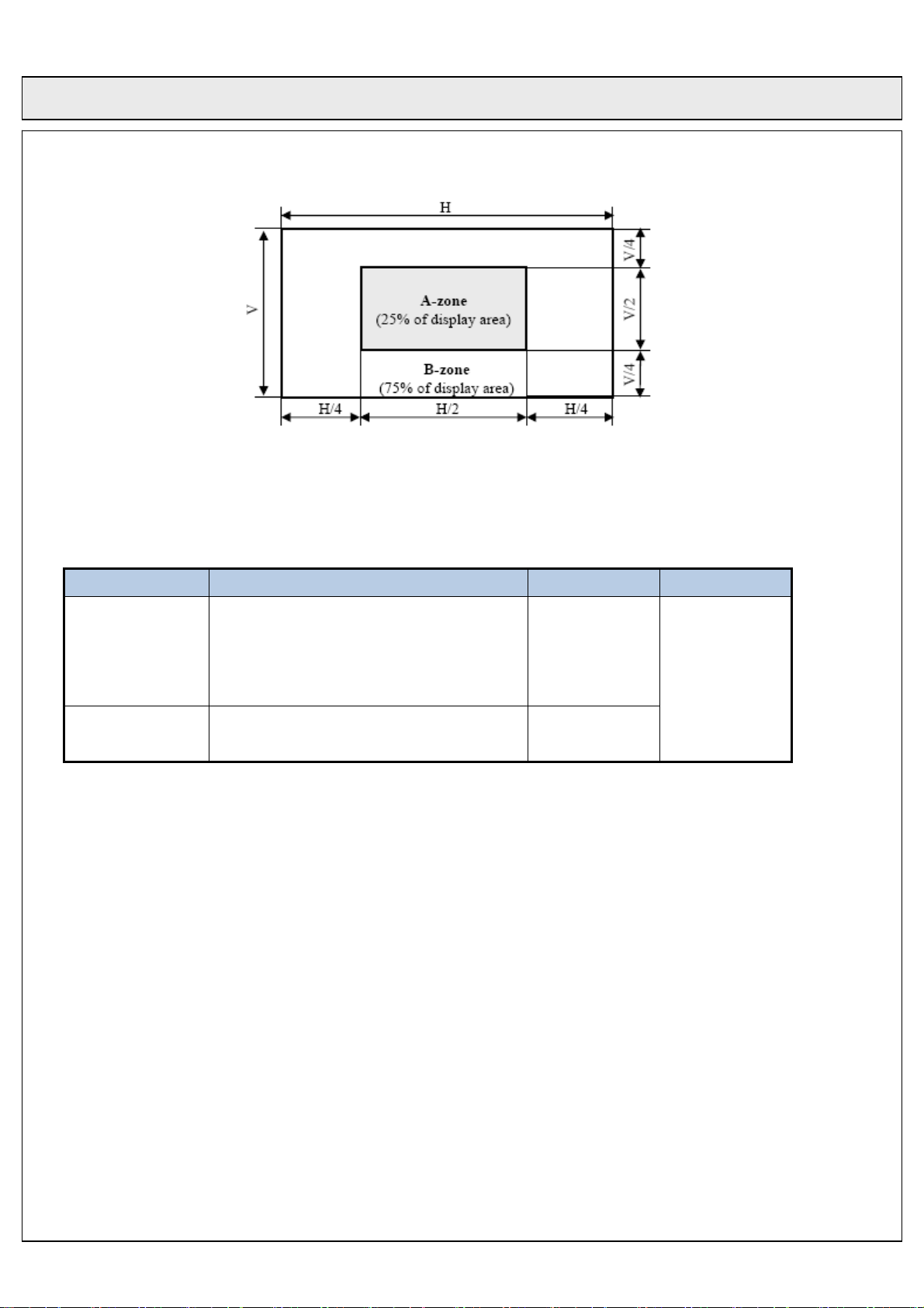
□ Cell Defect Specifications
Defect
Non-lighting Cell ☞1)
Non-extinguishing
☞2)
Cell
Flickering Cell☞3)
Product Specification of 50HD-PDP Module
APPENDIX
Specification
Number of Cell Defects (N) Distance between two defects (D)
A-zone
B-zone
A-zone
B-zone
A-zone
▶ 3 and less
▶ 6 and less
▶ 0
▶ 0
▶ 0
(the W/R/G/B screen)
Flickering Cell☞3)
(the other screen)
High Intensity Cell
☞4)
2 or 3 Continuous
Cell
☞5)
▶ Total sum of all defects N ≤ 12 and less
Stain ☞6)
B-zone
A-zone
B-zone
A-zone
B-zone
A-zone
B-zone
▶ N ≤ 3, for the stain of which longer-axis
▶ N = 0, for the stain of which longer-axis
▶ 0
▶ 0
▶ 0
▶ 1
▶ 2 and less
▶ 1 and less
▶ 2 and less
length is 3 mm or shorter.
length is longer than 3 mm.
▶ Regardless of A and B Zone,
the distance between two defect-
cells is more than 71mm. (In case
of continuous cell, more than
141mm)
▶ D > 141mm
☞1) Non-Lighting Cell is defined as “A cell which is always off”.
☞2) Non-extinguishing Cell is defined as “A cell which is always on”.
☞3) Flickering Cell is defined as “A cell which is flickering”.
☞4) High Intensity Cell is defined as “A cell which is brighter than a correct cell”.
☞5) The vertical continuous defect cell is not allowed.
☞6) Stain is defined as “A blob due to local color contamination in white or simple color pattern”.
Rev. No. : 0.0 2009. 12. 18. 35/37
Page 36
COC Display Devices Co., Ltd. TENTATIVE No. :
Product Specification of 50HD-PDP Module
□ Scratch and Dent Specification
Item Spec Unit Remark
W ≤ 0.01 : ignored
Scratch
Dent
0.01≤W≤0.09, 0.3≤L≤25.4, N≤1
0.1≤W≤0.14, L≤12.7, N≤1
0.1≤W≤0.14, L≤12.7, N≤1
D ≤ 0.75, N ≤ 6
□ Sound Pressure Level Specification
1) Level Ground (Land)
- Measuring Condition : 0m
- Sound Pressure Level is overall level calculated from the individual band levels of 250Hz ~ 8KHz.
- Spec : 31 dB Max
2) High Ground
- Measuring Condition : 1600 m
- Sound Pressure Level is overall level calculated from the individual band levels of 4KHz ~ 12.5KHz.
- Spec : 37 dB Max
[Note]
mm
W : Width
L : Length
D : Depth
N : Number
mm
1) Audible noise is guaranteed till the altitude of 1,600 meter.
2) In order to guarantee audible noise at higher altitude 1,600 meter, a special module has to be used.
Rev. No. : 0.0 2009. 12. 18. 36/37
Page 37
COC Display Devices Co., Ltd. TENTATIVE No. :
Product Specification of 50HD-PDP Module
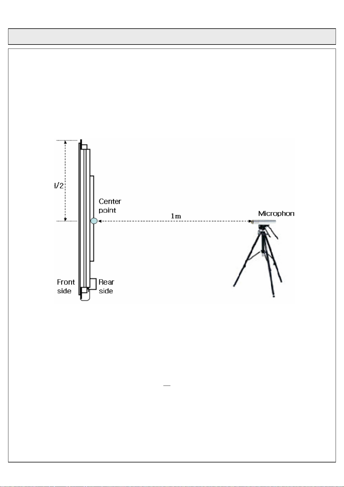
ound Pressure Level Measuring Condition
* S
(1) Environment: Anechoic chamber
(2) Background noise level: less than 20dBA
(3) Equipment: FFT Analyzer
i. Type2827 made by B&K
ii. PAK system v5.3 above made by MULLER-BBM
(4) Distance : 1.0m from the center of rear side of PDP
Figure 14 - Measuring layout
ound Pressure Level Measurements
* S
(1) Pattern: Full white pattern
(2) Frequency Range: 250Hz ~ 8kHz
(3) Bandwidth: ⅓ Octave band
(4) Weighting: A-weighting
Overall value is sum of Sound Pressure Level which is calculated from the individual
band of 250Hz~8kHz.
⎛
⎞
P
⎜
=
Where,
SPL
log20
0
⎟
10
dBA
⎜
⎟
P
0
⎝
⎠
6
paP
1020−×=
Rev. No. : 0.0 2009. 12. 18. 37/37
 Loading...