

Page 1
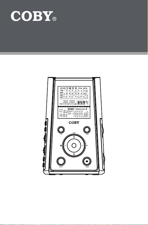
CR-A149
O
Projection AM/FM Alarm Atomic Clock
Radio with Temperature Display
INSTRUCTION MANUAL
Please read this manual carefully before operation
Page 2
www.cobyusa.com Page 3
PRECAUTIONS
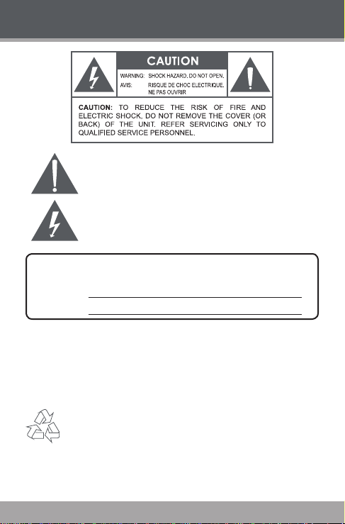
The lightning as h with arrowhead symbol within an e quilateral triangle
is inten ded to aler t the user to the presenc e of uninsulate d “dangerous
voltage” within the product ’s enclo sure that may be of suf cient magnitude to co nstitute a risk of electr ic shock.
The exclamatio n point with in an equilat eral triang le is intende d to alert
the u ser to th e presence of impor tant oper ation and servicing instructions in t he literature ac companying the a ppliance.
For Cus tomer U se:
Enter below the serial number t hat is located on the unit. Retain this information for f uture reference.
Model N o. CR-A149
Seri al No.
WARNI NG:
To prevent re or shock hazard, do not expose thi s device to rain or moistur e. Dangerous high
voltage is presen t inside the enclo sure. Do not open th e cabinet.
CAUTIO N:
To prevent elec tric shock, match wide bl ade of plug to wide sl ot of outlet and fully inser t.
For recycling or disposal information about this product, please contact your
local au thorities or t he Electronic s Industries A lliance: www.ei ae.org.
Page 2 Coby Electron ics Cor por ation
Page 3

IMPORTANT SAFETY INSTRUCTIONS
1.
Read Ins truc tions: All the safety and operati ng instructions sho uld be read
before th e produc t is operat ed.
Retai n I nstr uctio ns: The safet y and operat ing instructions should be re-
2.
tained f or future r eferenc e.
Heed Warnings: All w arnings on the p roduct and in the oper ating instru c-
3.
tions sh ould be adhe red to.
Follow Instructions: All operating and usage instructions should be followed.
4.
Cleaning: Unplug this product from the wall outlet before cleaning. Do not use
5.
liquid cleaners or aeros ol cleaners. Use a damp cloth for cleaning.
Attac hment s: Use only attac hments recommen ded by the manufactu rer.
6.
Use of othe r attach ments may be h azardo us.
Water and M oistur e: Do n ot use this p roduct near wa ter (e.g., n ear a b ath
7.
tub, washb owl, kitchen sink , laundr y tub, in wet basement s, or near a swimming poo l and the like).
Acces sorie s: Do not place this pro duct on an unst able
8.
cart , stand, trip od, bracket, or ta ble. Use only with ca rts,
stands, trip ods, brackets, or tables recomme nded by
the m anufacturer or so ld wi th th e pro duct. Any mounting of t he produ ct shoul d follow the manu factur er’s
instru ctions and shou ld u se a mounting acce ssor y re commended by the manu facture r.
A produc t a nd cart combinat ion should b e moved with c are. Quick st ops,
9.
excessi ve force, and un even surf aces may ca use the prod uct and car t combinatio n to overtu rn.
Ventil ation: Sl ots and openin gs in the cabinet are provided fo r ventilati on to
10.
ensure reliab le op eration of the product and to protect it from overheat ing.
These openin gs sh ould never b e blo cked by placing th e pro duct on a bed,
sofa, rug, or other s imilar surface. This pro duct should no t b e pl aced in a
built- in ins tallati on such a s a bookc ase o r rac k unl ess proper ventilation is
provide d or the manu facture r instru ctions ha ve been adhe red to.
Power Source s: This produc t should be op erated only from the type of
11.
power so urce in dicated on the r ating la bel. If y ou are no t sure of the typ e of
power supp ly to your home, c onsult your p roduct de aler or local power com pany. For produc ts intende d to operate fro m batter y power or othe r sources,
refer to th e operati ng instru ctions .
Grounding or Polari zation: This product may be equipped w ith a polari zed
12.
alternating-current line plug that has one blade wider than the other. This plug
will only t into the power outlet in one direction. This is a safety feature. If you
are unable to insert the plug fully into the outlet, t ry reversing the direction of
the plug. If the plug s hould still f ail to t, contact an electrician to replace the
obsolete outlet. Do not defeat the safet y purpose of the polarized plug.
www.cobyusa.com Page 3
Page 4
www.cobyusa.com Page 5
IMPORTANT SAFETY INSTRUCTIONS
13.
Power- Cord Prot ecti on: Power supply co rds should be routed so that they
are not likely to be walked on or pinche d by items pl aced upon or against
them, paying par ticul ar attention to cords at plugs, convenien ce recepta cles,
and at the po int which t hey exit fro m the prod uct.
Protec tive Attach ment Plug: The p roduct may be equ ipped with an at-
14.
tachme nt plug w ith overload protection. This is a safety feature. See the
operat ing instru ctions for rep laceme nt o r di rectio ns to r eset the protective
device. If replace ment of the plu g is require d, be sure the s ervic e technic ian
has us ed a replac ement plug t hat has the same ove rload protec tion as the
origin al plug as sp ecied by the manufa cturer.
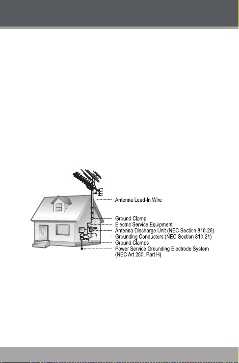
Outdo or Ante nna Groun ding: If an outside antenna is c onnecte d to t he
15.
produc t, be sure the antenna system is grounde d so as to provide some
protection against vol tage su rges an d built- up sta tic cha rges. A rtic le 810 of
the Nationa l Electric al Code, ANS/N FPA 70 provides informat ion with regard
to pro per grounding of the mast and suppor ting struct ure, gr ounding of the
lead- in wire to an antenna -disc harge unit, size of groundi ng conductors ,
locati on of antenna -disc harge unit , connec tion to grou nding elec trodes , and
require ments for t he ground ing elect rode (see g ure).
Light ning: For added protect ion for this product, unplug it from the wall
16.
outlet and di sconnec t the antenna or ca ble sys tem dur ing a lightnin g stor m
or w hen it is left una ttende d and unused fo r lo ng p eriods of time. This will
prevent dam age to the pr oduct due t o lightnin g or power-l ine surge s.
Power Lin es: An outsi de antenna system should not be lo cated in the vicin-
17.
ity of overhead power lines or other elect ric light or power circ uits, or where it
can fall i nto such pow er lines or c ircuits . When inst alling an ou tside ant enna
system, extreme care s hould be take n to keep from to uching such power
lines or c ircuits , as contact with th em might be fa tal.
Page 4 Coby Electron ics Cor por ation
Page 5

IMPORTANT SAFETY INSTRUCTIONS
18.
Overl oading : Do not overloa d wall outlets , extension cords, or inte gral con -
venienc e recept acles as t his can res ult in a risk of re or electric sh ock.
Objec t and Liqui d Entr y: Never push objects of a ny kind into th is product
19.
throug h openin gs as th ey may tou ch dange rous vol tage po ints or shout- out
parts that could result in a re or el ectric s hock. Neve r spill liqui d of any kind
on the pro duct.
Serv icing: Do not attempt to ser vice this produc t yourse lf as opening or
20.
removin g c overs may expo se you to danger ous voltag e or other hazards.
Refer all se rvic ing to quali ed ser vice pe rsonnel .
Damag e Re quiri ng S ervi ce: U nplug this produ ct f rom the w all o utlet and
21.
refer ser vicin g to quali ed serv ice pers onnel und er the foll owing con ditions :
a) whe n the power-supply or plug is damaged; b) if liquid ha s be en sp illed
or if obj ects hav e fallen i nto the pr oduct; c) if the pr oduct ha s been exp osed
to rain or water; d) if the produc t does n ot opera te norm ally by fo llowing the
operat ing instruction s. Adjust only those c ontrol s that are c overed by t he
operat ing instru ctions as impr oper adjus tment of other co ntrols may resu lt in
damage and w ill often r equire ext ensive wor k by a qualied te chnicia n to restore the p roduct to i ts norma l operation; e) if the prod uct has bee n dropped
or damage d i n any way; f) when t he produc t exhibits a dis tinct change in
perf ormanc e—th is indicates a need fo r servi ce.
Repla cemen t Part s: When replacem ent parts are required, be sure that
22.
your ser vice technic ian has u sed repl acemen t part s speci ed by th e manufactur er or have the same charac teristics as t he orig inal par t. Una uthori zed
substit utions may result in r e, electr ic shoc k, or other ha zards.
Safet y Check: Upon c ompleti on of a ny s ervic e o r r epairs to this product,
23.
ask the se rvice technic ian to per form sa fety che cks to ensur e that the product is in pr oper oper ating co ndition .
Wall or Ceiling Mounting: The product should be mo unted to a wall or
24.
ceilin g only as rec ommende d by the manu facture r.
Heat: The produc t sho uld b e sit uated away f rom h eat s ources such as ra-
25.
diators , he at re gisters, st oves, or o ther produc ts ( includi ng a mplier s) tha t
produc e heat.
www.cobyusa.com Page 5
Page 6

www.cobyusa.com Page 7
TABLE OF CONTENTS
PRECAUTIONS .............................................................................. 2
IMPORTANT SAFETY I NSTRUCTIONS ........................................... 3
TABLE OF CONTENTS ................................................................... 6
FEATURES ...................................................................................... 7
GETTING S TARTED ........................................................................ 8
CR-A149 at a Glance .................................................................................. 8
Top View ...........................................................................................8
Front View .........................................................................................8
Rear View .........................................................................................8
Right Vi ew.........................................................................................9
Left Vi ew ........................................................................................... 9
Power Connection ....................................................................................10
AC Power ........................................................................................10
Batter y Backup ............................................................................... 10
Reset ...............................................................................................10
Preparing the CR- A149 for Use................................................................ 11
CLOCK/ALARM MODE .............................................................. 12
Setting the Cloc k Time and Date .............................................................12
Setting the Alarm Timer............................................................................ 13
Turning the Alarm Timer On/Off (Alarm Mode) .............................14
Snooze Func tion ............................................................................14
Setting the Sleep Timer ............................................................................15
TEMPERATURE READING ........................................................... 16
Indoor Temperature ..................................................................................16
Outdoo r Temperature ...............................................................................16
Wirele ss Outdo or Temperature Sensor .........................................16
PROJECTION SYSTEM ................................................................ 18
RADI O MODE ............................................................................. 19
Basic Op eration ........................................................................................19
Tuning .............................................................................................19
Reception .......................................................................................19
TROUBLESHOOTING .................................................................. 20
SPECI FICATIONS ........................................................................ 21
Page 6 Coby Electron ics Cor por ation
Page 7

FEATURES
Thank you for purchasing a COBY CR-A149. Please read through this
manual c arefully in order to have a better understanding of the performance and features of your alarm clock radio.
Dual projectors display the time and ind oor/outdo or temperature
Wireless outdoo r temperature transmitter (max. 100’ operating
distanc e)
Automatic daily clock synchronizat ion with t he ofcial US atomic
clock (accurate to wi thin one second)
Digital Time and Date Display w ith Back light
Dual Alarm Clock Settings
Snooze/Sleep Function
Wake to Music or Buzzer
AM/FM Radio
www.cobyusa.com Page 7
Page 8
www.cobyusa.com Page 9
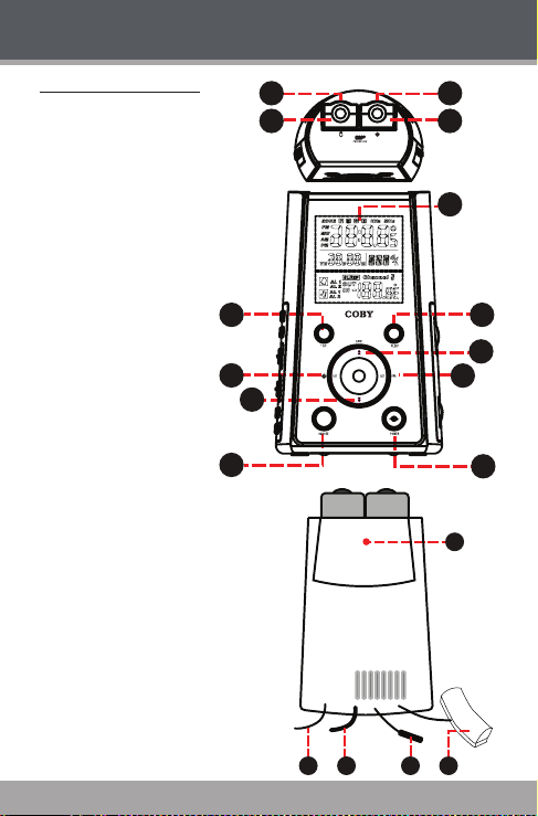
CR-A149 at a Glance
11
9
1
2
3
4
5
6
10
8
12
7
13
O
151416
17
18
Top View
Temperature Focus Dial
1.
Temperature Pr ojector
2.
Clock Foc us Dial
3.
Clock Projector
4.
Front V iew
Clock Di splay
5.
Temperature Mode
6.
Sleep
7.
Date / Up
8.
Alarm Set
9.
Clock Set
10.
Down
11.
Snooze
12.
Power
13.
Rear View
Reset But ton
14.
FM Antenna
15.
AC Power Cord
16.
Temperature Sensor (Indoor)
17.
RCC Antenna
18.
(Radio Controlled Clock)
GETTING STARTED
Page 8 Coby Electron ics Cor por ation
Page 9

ON OFF
23
21
19
20
22
24
26
28
25
27
29
GETTING STARTED
Right View
Radio Tuning Dial
19.
Radio Frequency Band
20.
Radio Tuning Indicator
21.
Volume Level Dial
22.
Radio Band Switch (FM, AM)
23.
www.cobyusa.com Page 9
Left View
Temperature Pr ojecti on
24.
(On/ Of f)
Clock Projection (On/Of f)
25.
Alarm M ode Switch
26.
(Radio, Buzz, Of f)
Alarm Select
27.
(Alarm 1, Alarm 2, Alarm 1+2)
28.
29.
Temperature Select
(Indoor/Outdoor)
Speaker
Page 10

www.cobyusa.com Page 11
GETTING STARTED
Power Connection
AC Power
This unit r uns on AC 120V power.
Plug the AC Power Cord into a 120V household electrical wall outlet.
Do not connect the power plug to a power outlet oth
er than that which is indicated here or on the label as
this may result in the risk of re or electric shock.
Do not handle the power plug with wet hands. D oing
so may cause electric shock.
Battery Backup
The battery backup f unction maintains the cloc k time should t he AC
power be interr upted. When power is restored, the correct time will
be displayed.
The battery compartment is loc ated on the bottom of t he unit. Load 3
x CR2025 lithium batteries (not included) in the bat tery c ompar tment.
Make sure that the positive (+) and negative (-) bat tery te rminals are
attached to the corresp onding terminals on the plate in t he battery
compar tment
The time will not be displayed nor will any functions
be available during power failure. Battery backup
maintains the time, only.
Reset
To reset the unit, press the RESET button located on the rear of the unit
(behind the pro jector s. Reset the unit if it is not performing as expected
and whenever the remote temperature senso r’s batter ies are changed.
Resetting the unit will r eturn all settings to their factory- default state
and all stored data will be lost (e.g., alarm and clock settings).
-
Page 10 Coby Electron ics Cor por ation
Page 11

GETTING STARTED
Prepa ring the CR-A149 for Use
Plug the clock into an AC 120V o utlet.
Press the RESET but ton located on the rear of the clock. Upon reset-
ting the clock:
The display will light up and ash
The temperature will be displayed for 4 seconds
The remote unit will se arch for the 433M Hz transmission signal in
5 minutes
The main unit will start searching for the RCC (Radi o Contro lled
Clock) signal automatically. The RCC signal w ill synchronize your
clock’s time and date (includin g Daylight Savings Time).
An anim ated antenna dish icon indicates that the unit is sear ching for a signal.
The antenna dish icon indicates that a signal has been
received.
The unit will stop searching
after 10 minutes if a signal
cannot be received
It will take up to 10 minutes for the signal to synchro
nize the clock time.
RCC synchronization may be turned on or off by
holding the snooze but ton for 3 seconds.
For best res ults, place the RCC antenna near a win
dow with a clear view of the sky. Keep the RCC antenna away fro m metal or electrical objects.
www.cobyusa.com Page 11
-
-
Page 12

www.cobyusa.com Page 13
CLOCK/ALARM MODE
Sett ing the Clock Time and Date
It is not necessary to set t he clock time unless you cannot receive the
RCC synchr onization signal. If you cannot receive a signal, or if you
want to set your clock manually, set the Cl ock Set opt ions.
To set the Clock Set options:
Hold the C LOCK SET button for 2 seconds to enter Clock Set
mode. Press the CLOC K SET button again to c ycle thro ugh the
Clock Set options.
To change an option value, pre ss UP or DOWN. When you have
nished s etting an option, press CLOCK SET to move on to the
next opti on.
The Clock Set options ar e: Language, Year, Month, Day, 12/24H, Time
Zone, RTC Hour, RTC Minute.
Clock Option Settings
Languag e ENG (English), GER (German), FRE (French),
Year (YR) 2000 to 2099
Month (M) 1 to 12 (January to December)
Date (D) 1 to 31
12/24H Select 12H or 24H time display
Hour Set the cur rent clo ck hour
Minute Set the cur rent clo ck minute
SPA (Spanish), ITA (Italian).
Default: ENG
Default: 2005
The week day will be automatically calculated once
the Year, Month, and D ate are set .
Page 12 Coby Electron ics Cor por ation
Page 13

CLOCK/ALARM MODE
Sett ing the Ala rm Ti mer
The CR-A149 features dual-alar m timers that can be set independently
of one another.
Set the AL ARM SELECT switc h to “AL 1” to use Alarm 1, only.
Set the AL ARM SELECT switc h to “AL 2” to use Alarm 2, only.
Set the AL ARM SELECT switc h to “AL 1 + 2” to use both Alarm 1
and Alar m 2 together.
To set the Alarm T imer opti ons:
Hold the A LAR M SET but ton for 2 seconds to enter Alarm Set
mode. Press the AL ARM SE T button again to cycle through the
Alarm Set options.
To change an option value, pre ss UP or DOWN. When you have
nished s etting an option, press AL ARM SE T to move on to the
next opti on.
The Alarm Set options ar e: AL1 Hour, AL1 Min, AL1 Weekend Alarm,
AL2 Hour, AL2 Min, A L2 Weekend Alarm.
Alarm O ption Settings
AL1 Hour Set the Alarm 1 hour.
AL1 Min Set the Alarm 1 minute.
AL1 Weekend Set the Alarm 1 Weekend m ode:
AL2 Hour Set the Alarm 2 hour.
AL2 Min Set the Alarm 2 minute.
AL2 Weekend Set the Alarm 2 Weekend m ode:
Mon- Fri (5 days), Mon- Sat (6 days), Mon -Sun
(7 days)
Mon- Fri (5 days), Mon- Sat (6 days), Mon -Sun
(7 days)
www.cobyusa.com Page 13
Page 14

www.cobyusa.com Page 15
CLOCK/ALARM MODE
Turning the Alarm Timer On/Off (Alarm Mode)
To turn the alar m on, set the A LARM MODE switch to the “ Radio”
or “Buz z” position.
To wake to radio, select the “Radio” posi tion. T he last radio station will play when the alarm tur ns on.
To wake to a buzzer, selec t the “Buzz” position.
Radio
To turn the alar m off, set the ALARM MODE switch to the “Off”
position.
When the alarm sounds, the alarm will continue
for 30 minutes unless you intervene. If no key is
pressed, the alarm will turn off automatically after
30 minutes.
Buzz
Snooze Funct ion
When the alar m sounds, you can turn the alarm of f temporarily for 9
minutes.
Press SN OOZE when the alarm s ounds. The alarm will resume
automatically af ter 9 minutes.
To turn the alarm off completely, you must set the ALARM MODE
switch to t he “Of f” position.
Page 14 Coby Electron ics Cor por ation
Page 15

CLOCK/ALARM MODE
Sett ing the Sleep Timer
The sleep timer allows you to go to sleep to music. The radio will turn
itself off automatically at the end of the timer. To set the sleep timer:
Press the SLEEP but ton. The Sleep Timer will ash on the display.
While the Sleep Timer is ashing, you can change the length of the
timer by pressing SLEEP again (9 0, 60, 30, and 15 minutes).
To cancel the Sleep Timer, press the POW ER button..
www.cobyusa.com Page 15
Page 16

www.cobyusa.com Page 17
TEMPERATURE READING
Front Rear
1
3
4
5
2
Indoor Temperature
The C R-A149 contains a built-in thermometer.
The unit will check the indoor temperature every 6 seconds.
The indo or temperature range is 0 – 50ºC or
32 – 122ºF.
To change between indoor and outdoor temperature display, press the
TEMPER ATURE SELECT button.
Outdoor Temperature
The CR-A149 c omes equipp ed with a wireless
outdoor temperature sensor. The outdoor sensor will check t he outdoor temperature every 6
seconds.
The outd oor temperature range is -20 – 60ºC
or -4 – 140 ºF.
To change between indoor and outdoor temperature display, press the
TEMPER ATURE SELECT button.
Wire less Outdoor Temperature Sensor
The outdoor temperature sensor
features an LCD display (1) and
low battery level indicator (2).
The outdoor temperature sensor
requires 2 x “AAA” batterie s.
Remove the screws on the
batter y compartment (5)
cover.
Set the temperature display unit switch (3) to ºC or ºF. The unit may
also be reset at this time by pressing the reset button (4).
Load the batteries into the compartment in the orientation indicated
by the diagram.
Page 16 Coby Electron ics Cor por ation
Page 17

TEMPERATURE READING
For best operation:
Load the batteries in the outdoor sensor before powering on the
main unit.
Although the outdoor sensor is weatherproof, it should be placed in
an area protected fr om direct sunlight, rain, and snow.
Place the main unit as c lose to the outdoor sensor as possible. The
maximum distanc e between the main unit and outdo or sensor is 15
to 20 meters (50 to 65 feet).
The transmission range may be affected greatly by
building materials and obstacles between the main
and remote unit. Try different positions to obtain the
best reception.
Low temperatures will decr ease the batteri es volt
age and ef fective transmission range.
Inter ference from other household devices (e.g.,
door bells, home securit y systems, wireless telephone systems , and wireless network routers) may
cause temporar y reception failure. This will no t
affect the general performance of the product as
transmission and reception of temperature readings
will resume once the interference recedes.
-
www.cobyusa.com Page 17
Page 18

www.cobyusa.com Page 19
PROJECTION SYSTEM
The CR-A149 contains two built-in projec tors that can display the time
and temperature on the ceiling or wall of a dar kened room.
Press the TEMPER ATURE PROJ ECTION button to tur n the
temperature projector on or off.
Press the CLOCK PROJ ECTION button to turn the clock projector
on or off.
Turn the dials on t he projection mechanism to focus the image on
the ceiling or wall.
The maximum projection distance is between 3 and
9 feet.
Page 18 Coby Electron ics Cor por ation
Page 19

RADIO MODE
Basic Operation
To turn the radio on, press the POWER button. (To turn the radio
off, press the POWER button again.)
Set the R ADIO BA ND switch to:
AM: Listen to AM broadcasts.
FM: Listen to FM broadc asts.
To adjust the volume level, turn the Volume Level dial
Tuning
Turn the Radio Tuning Dial to tune to a de sired broadcast station.
The current station is displayed by the Radio Tuning Indicator/
Radio Frequency Band.
Recept ion
For FM broadcasts, ex tend the FM antenna fully and adjust its
position for best r eception (the FM wire antenna is located on t he
rear of the unit).
For AM broadcasts, the unit should be positioned for best signal
strength (the AM antenna is built into the unit).
www.cobyusa.com Page 19
Page 20

www.cobyusa.com Page 21
TROUBLESHOOTING
If you have a problem with this devic e, please read the troubleshooting
guide below and check our website at www.coby usa.com for Frequently
Asked Q uestions (FAQs) and rmware updates. If these resources do
not resolve the problem, please contact Technical Support.
COBY Electronics Technical Support
Address: 56- 65 Rust S t.
Hours: 8:30 A M–11:00 PM EST, seven days a week
Phone: 800 -681-2629 or 718- 416-3197
Email: techsupport@c obyusa.com
Web: www.cobyusa.c om
Maspeth, NY 11378
There is no power to the devic e.
Ensure that the power cord is securely connected to the unit and the
proper wall outlet.
There is no sound.
Try adjusting the volume.
Ensure that nothing is c onnected to the AUD IO IN jack .
The sound is distor ted.
The unit may be positioned too closely to a large appli ance (e.g., a
TV or ref rigerator). If possible, tur n the appli ance of f or move the
unit to another location.
Ensure that the radio is in broadc ast reception range.
Decrease the volum e level.
Page 20 Coby Electron ics Cor por ation
Page 21

SPECIFICATIONS
Power Supply AC 120V ~60 Hz
Batter y Backup 3V Flat Lithium CR2025 x 3
Remote Sensor 1.5V “AAA” x 2
Tuning System AM: 5 30 - 1710kHz
RCC Carr ier Frequency 60kHz
RCC Station WWVB
Audio Output Full-Range Speaker
Output Power 350mW
Speaker Impedance 8Ω
5W
FM: 88 - 108MHz
Speci cations and manua l are subje ct to chang e withou t notice.
www.cobyusa.com Page 21
Page 22

www.cobyusa.com Page 23
NOTES
Page 22 Coby Electron ics Cor por ation
Page 23

NOTES
www.cobyusa.com Page 23
Page 24

COBY Electronics Corp.
56- 65 Rust Street
Maspeth, NY 11378
ww w.cobyusa.com
ww w.ecoby.com
 Loading...