

Page 1
Service Manual
Service Manual
TELEVISION SET
WITH 32” 16:9 TFT LCD PANEL
Model : TFTV3225S2
Copyright 2010 COBY Electronics Co., Ltd.
All Right Reserved
Sep. 30th, 2010 (Version 1.3) Page 1 / 21
Page 2
Service Manual
CONTENTS
Notes For Installation………………………………………………………………..3
Specifications…………………………………………………………………………4
Block Diagram………………………………………………………………...……...7
PCB Mechanical Dimension………………………………………………………..8
Board Connectors Pin Assignment……………………………………………...9
Exploded View………………………………………………………………….……13
Schematic…………………………………………………………………………….14
Trouble Shooting Flow Chart……………………………………………………..19
Sep. 30th, 2010 (Version 1.3) Page 2 / 21
Page 3

Service Manual
Notes For Installation
This television set with 32’’ FT LCD panel, is designed mainly for receiving ATSC/NTSC system
TV source,or other sources such as DVD player and personal computer(TFDVD3295S2 Model),
via all diffident kinds of cables. This section provides some guidelines for assembly and
preparation of a finished display solution.
Preparation : Before proceeding, it is important to familiarize yourself with the parts making up the TV
Set and the various connectors, mounting holes, and general layout of the TV Set.
All connectors have their own number printed on the PCB board. And their signal
arrangements are shown in the following relevant sections.
4 LCD Panel : This TV Set has 12V,LVDS interface logic on the main board, for 32” TFT LCD panel.
Due to the different signal timing and electrical characteristics from each LCD panel
manufacturer, we need to use different Firmware, different LCD interface cable for
LCD panel even on the same board.
Inverter : Each LCD panels have their own inverter to obtain optimum performance and long lifetime.
Because, Each LCD panel makers use different type of back light tubes for their all different
models and inverter drives the tubes directly.
The main board of this TV Set just supplies the power for inverter logic and controls a light On/off signal
and a brightness control signal. So, it is important to use the inverter that has proper driving capacity and
control input signal. Generally speaking, the inverter is attached to TFT LCD panel, you should contact
with panel maker for any problem with the inverter.
Inverter cable : This cable supplies Inverter’s power, an on/off control signal and a brightness control
signal to the inverter.
OSD Button : See Operational Function section.
3 Color LED : This LED shows the state of TV Set.
• Green – Normal state
• Red – Stand-by mode
AC power input : 100Vac~240Vac(50/60Hz) is required to supply enough power for the TV Set.
Sep. 30th, 2010 (Version 1.3) Page 3 / 21
Page 4
Service Manual
Specification
Electrical Specification
a. Power Consumption: (Include Inverter and LCD Panel)
Operation mode
Power Consumption : 32’’ 150 Watt(Max)
Audio AMP : 9 +/-1Watt (Reference : Speaker 9W×2)
Power Saving mode (STB) : ≦1 Watt
b. Power Supply
Input for Main board : +12/5Vdc
Output for LCD Panel :32’’ 12Vdc
c. Environment
Operation Temperature : 0° ~ 45°
Storage Temperature : -20° ~ 70°
Operation Humidity : 0%~80% (non-Condensing)
Storage Humidity : 0%~90%
d. Output Data Type
LDVS mode : 8bit data output.(single LVDS output)
e. Input Refresh Rates : fH: 30~60KHz, fV: 60~75Hz
Power Board Specification
a. AC Input Requirements
Normal Voltage : 100 to 240 Vrms
Voltage Range : 90 to 264 Vrms
b. Frequency
Normal Frequency : 50 to 60 Hz
Frequency Range : 45 to 65 Hz
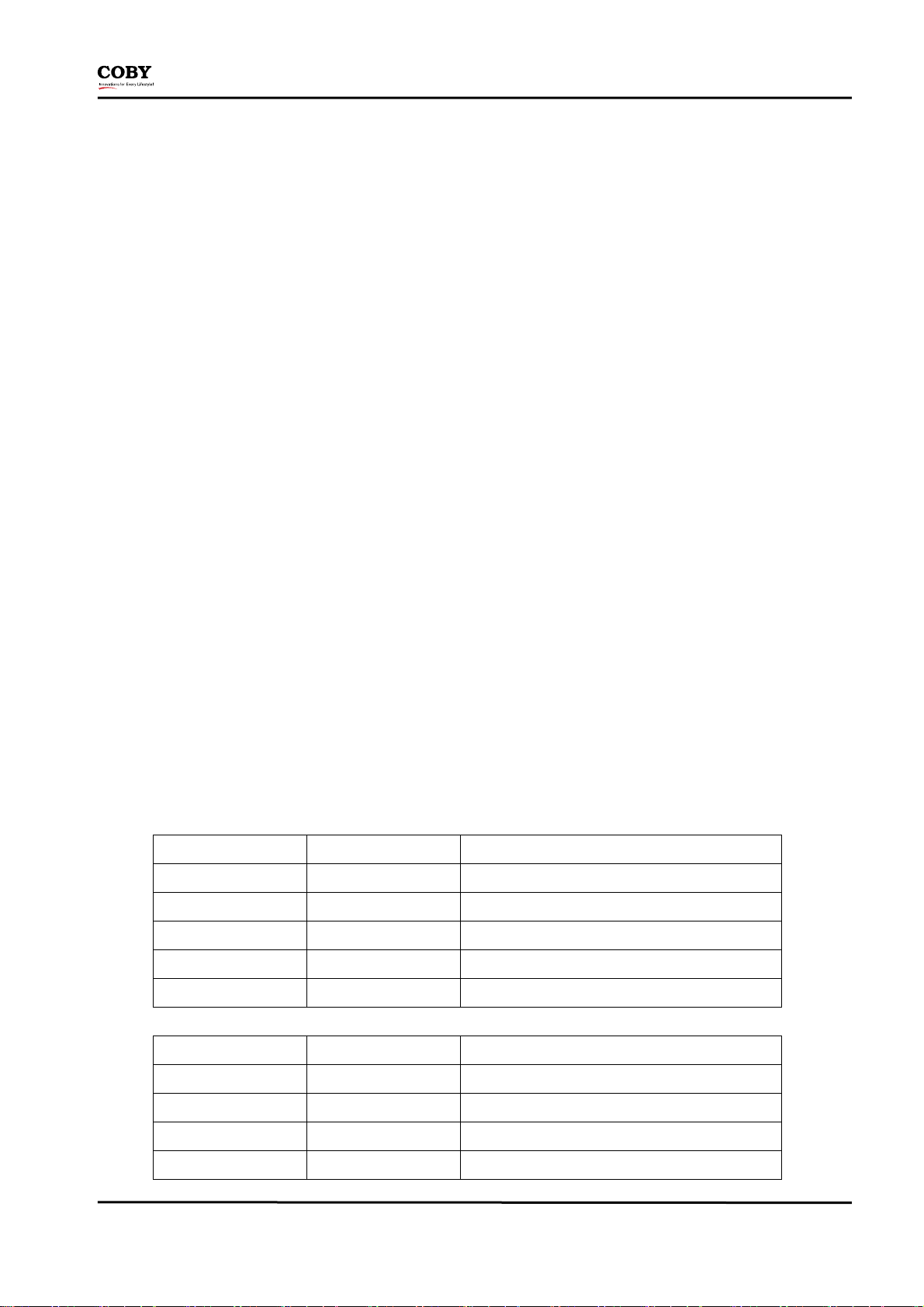
Pin-CON15 Connection to main board
NO. PIN Connection Function
9,10 +12V For tuner power and amp
6,7 +5V For scaler power and decoder power
4,5,8,11,12 GND +12/5Vdc return
1 ON/OFF
2,3 +5VSB MCU +5V, in standby power
Pin-CON3 for inverter PUB
NO. PIN Connection Function
1,2 GND For tuner power and amp
3 ADJ Adjuct backlight
4 ON/OFF Cut on/off panel backlight
5,6 +12 (out put) For inverter power
Work / standby mode (H working, L standby)
Sep. 30th, 2010 (Version 1.3) Page 4 / 21
Page 5

Service Manual
Television Part
Item Specification
TV SYSTEM ATSC/NTSC
SOUND
EXT.
TERMINAL
CAPTION CLOSED YES
Parental Control YES
PIP/POP NO
TV SYSTEM STEREO/MONO
SOUND OUTPUT 9W X 2
ASP YES
EFFECT No
COMPONENT 1
(YPbPr)
AV IN
PHONES YES
TUNER DIGITAL+Analog tuner(TCL)
Y/Pb/Pr INPUT
VIDEO, Y/C INPUT
AUDIO L/R INPUT
HDMI IN
RGB (PC-VGA15) Part
a. Features of Analog RGB Part
. Horizontal Rate: 31KHz ~ 60KHz
. Vertical Rate: 43 ~ 85Hz
. Maximum Pixel Rate: 78.75MHz
. Resolution Maximum: 32’’ 1280 x 1024
. Color Maximum: 262,114/16.7M(option)
. Sync type: H & V separate
. Plug & Play: YES DDC
b.
This board can detect all VESA standard Graphic modes (for Analog RGB) shown on the table below and provide more
VGA(PC) IN
VGA(Analog RGB) INPUT
PC-AUDIO(L/R) INPUT
DIGITAL AUDIO AND VIDEO (VIDEO AT RESOLUTION UP TO
1080P)
clear and stable image on a screen.
Sep. 30th, 2010 (Version 1.3) Page 5 / 21
Page 6
Service Manual
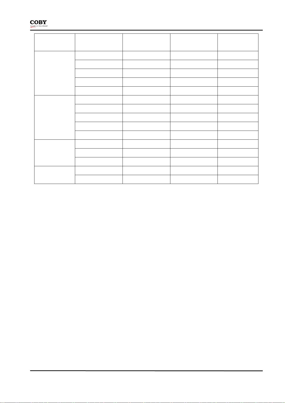
Standard Format Total Pixels x Total Lines
Horizontal rate
(KHz)
720 x 400p 70 Hz 900 x 449 31.5 28.0
640 x 480p 60 Hz 800 x525 31.5 25.2
Pixel Clock Rate
(MHz)
VGA
SVGA
XGA
SXGA
640 x 480p 67Hz 864 x 525 35.0 30.0
640 x 480p 72 Hz 832 x 520 37.9 31.5
640 x 480p 75 Hz 840 x 500 37.5 31.5
800 x 600 56 Hz 1024 x 625 35.2 36.0
800 x 600 60 Hz 1056 x 628 37.9 40.0
800 x 600 72 Hz 1040 x 666 48.1 50.0
800 x 600 75 Hz 1056 x 625 46.9 49.5
832 x 624 75 Hz 1152 x 667 49.7 57.5
1024 x 768 60 Hz 1344 x 806 48.4 65.0
1024 x 768 70 Hz 1328 x 800 56.4 75.0
1024 x 768 75 Hz 1312 x 800 60.0 79.0
1280 x 1024 75 Hz 1688 x 1066 39.2 135.0
1152 x 870 75 Hz 1456 x 916 68.9 100.0
Sep. 30th, 2010 (Version 1.3) Page 6 / 21
Page 7
Service Manual
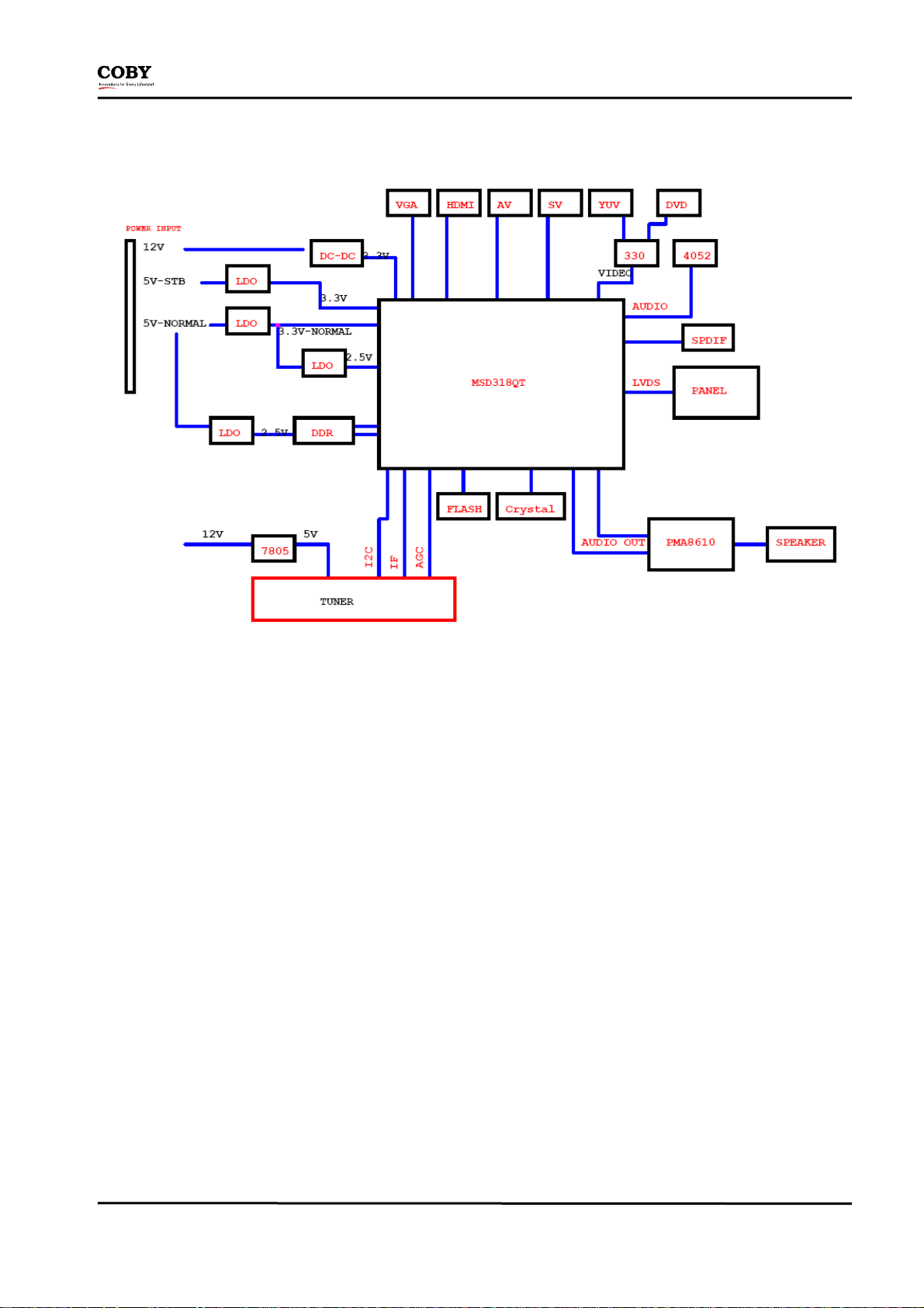
Block Diagram
Note:
1) The flash’s capability will be 32 mb(4MB) while adopt firmware which is more effective and stable
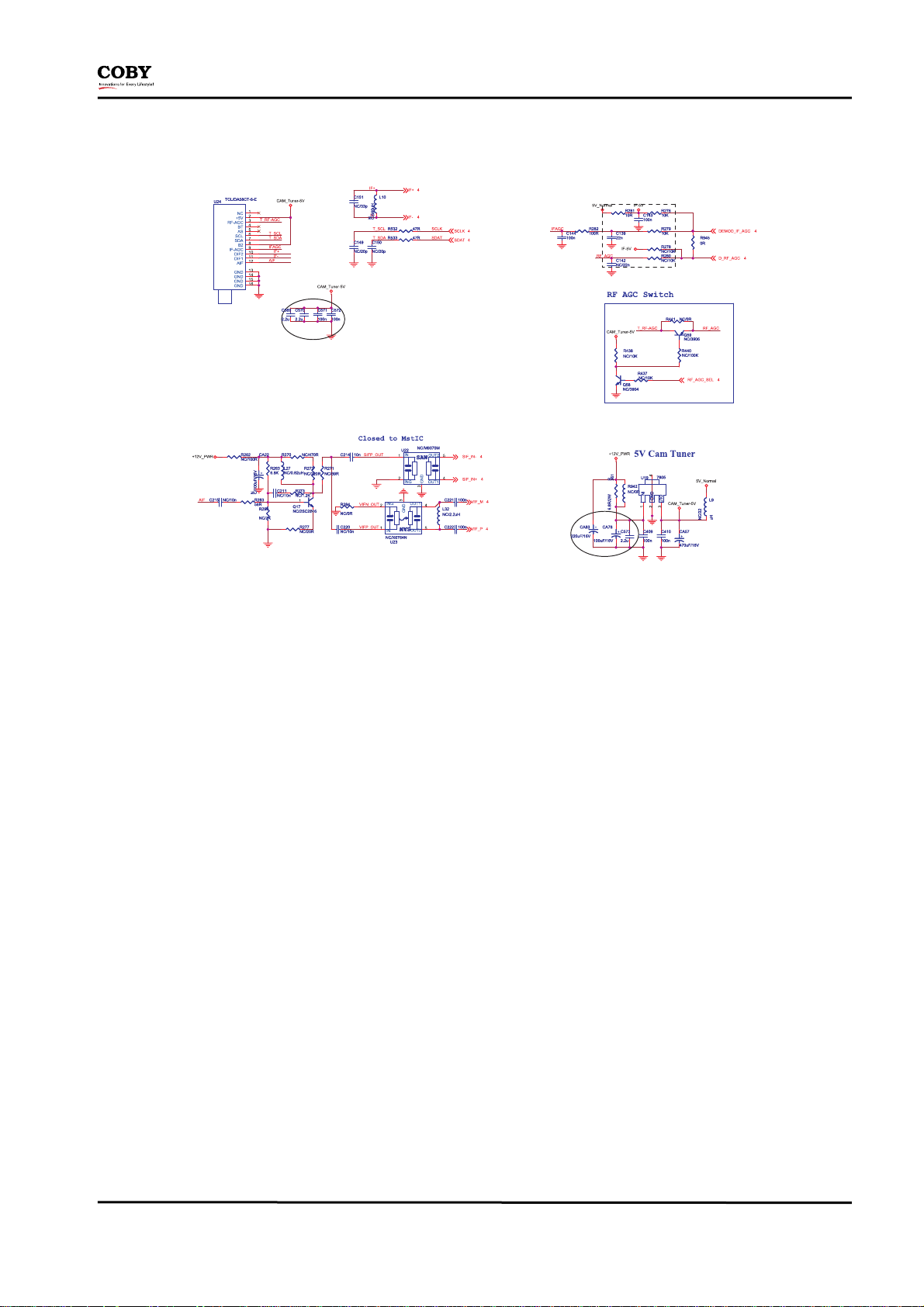
2) The Tuner may also be used with DA58CT-6-E.
3) Key & IR part will be divided into three PCB boards. A IR PCB board, a light board ( standby mode is blue low-light, the
work mode does not shine or high-lights, you can press the light button on the remote control to select the low-light
or high-light), another piece of the key board.
Note:
The TFTV MODEL is supplied by Coby, you can contact with COBY service department
Sep. 30th, 2010 (Version 1.3) Page 7 / 21
Page 8

Service Manual
PCB Mechanical Dimension
TV main board:
a. TOP Pattern:
Key & IR Board Component
a. Key Pattern
b. IR Pattern
Sep. 30th, 2010 (Version 1.3) Page 8 / 21
Page 9
Service Manual
Board Connectors Pin Assignment
a. CON24: 40 Pin define for Connector to Panel (NC 36 or 40 PIN, On Main Board):
LCD panel for example:SAMSUNG 32” panel
PIN Description PIN No. Description
1 GND 21 RXE2+
2 GND 22 RXE23 RX00+ 23 RXEC+
4 RX00- 24 RXEC5 RX01+ 25 RXE3+
6 RX01- 26 RXE37 RX02+ 27 RXE4+
8 RX02- 28 RXE4-
9 RX0C+ 29 GND
10 RX0C- 30 GND
11 RX03+ 31 GND
12 RX03- 32 GND
13 RX04+ 33 VCC
14 RX04- 34 VCC
15 GND 35 VCC
16 GND 36 VCC
17 RXE0+ 37 IIC-SCL
18 RXE0- 38 IIC-SDA
19 RXE1+ 39 GND
20 RXE1- 40 GND
b. CON33: Connector from Main Board to IR Board (5PIN, On Main Board)
PIN Symbol Description
1 5VSB Power Supply of IR Board +5V (standby 5V)
2 GND Power Supply of Ground
3 IR IR Receive
4 LED
5 GND Power Supply of Ground
6 SAR0 Key select pin Connect (The connected voltage: 0V/0.55V/1.1V/1.65V, not connected voltage: 3.3V)
7 SAR1 Key select pin Connect (The connected voltage: 0V/0.55V/1.1V/1.65V, not connected voltage: 3.3V)
Interrupt Input of Remote Controller (low-light ≧2.6~2.7V, High-light >3V, not light < 2.5V)
Sep. 30th, 2010 (Version 1.3) Page 9 / 21
Page 10

Service Manual
c. CON37/38: Connector from Main Board to Left/right Speaker (4PIN, On Main Board)
PIN Symbol Description
CON37 1 R+ Driving the Right Speaker(+)
CON37 2 R- Driving the Right Speaker(-)
CON38 1 L- Driving the Left Speaker(-)
CON38 2 NC NC
CON38 3 L+ Driving the Left Speaker(+)
d. P7: Connector of VGA(P-Scan) Input (15Pin, On Main Board)
PIN Symbol Description
1 R Analog Red Channel
2 G Analog Green Channel
3 B Analog Blue Channel
4 NC No Connection
5 GND Power Supply of Ground
6 R-GND Ground Return of Analog Red Channel
7 G-GND Ground Return of Analog Green Channel
8 B-GND Ground Return of Analog Blue Channel
9 VGA5V Power Supply of +5V
10 GND Power Supply of Ground
11 NC No Connection
12 VGA-SDA I2C Bus serial data input/output (For VGA)
13 A-HS Horizontal Sync Signal of Analog RGB
14 A-VS Vertical Sync Signal of Analog RGB
15 VAG-SCL I2C Bus serial clock input (For VGA)
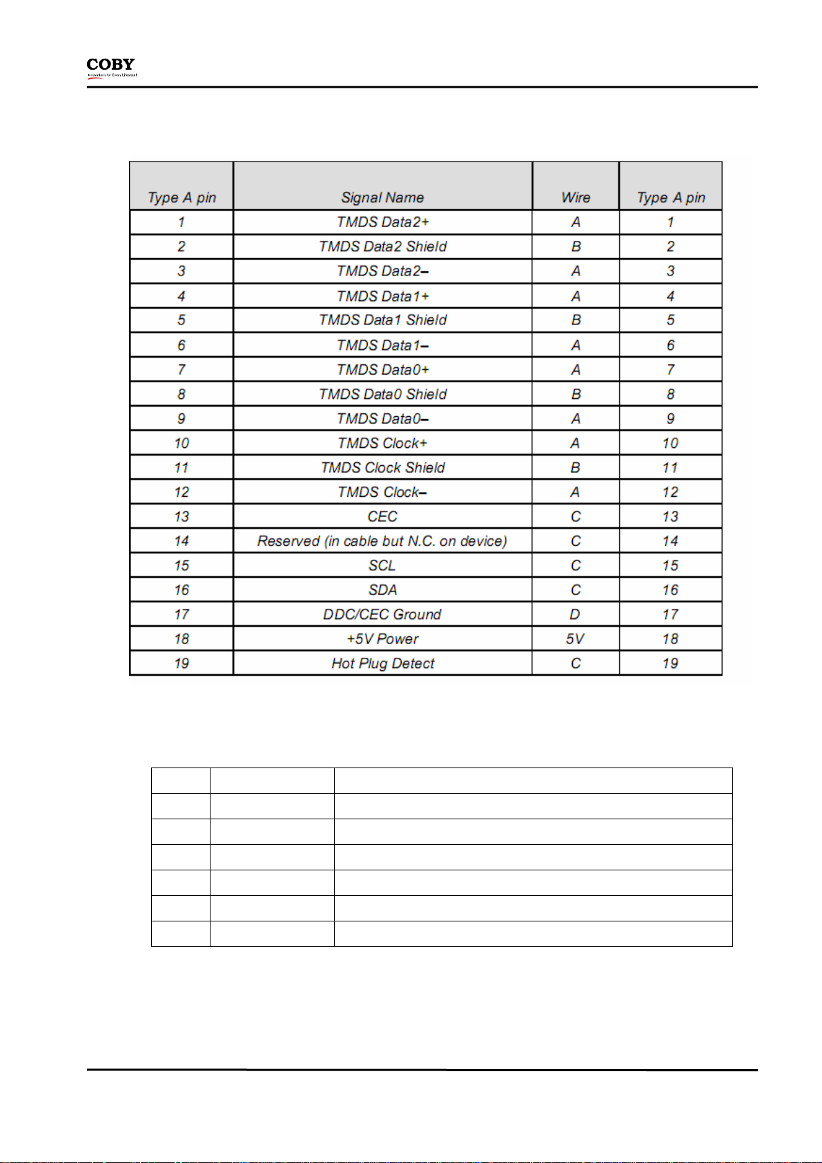
Please refer to High-Definition Multimedia Interface Specification Version 1.3a, for define of
all of the Pins above p4:PHONES Connector of PC-Audio INPUT
PIN Symbol Description
1 PC-L PC-Audio Left Channel
2 PC-R PC-Audio Right Channel
Sep. 30th, 2010 (Version 1.3) Page 10 / 21
Page 11
Service Manual
e. CON10/11: Connector of HDMI (19pin) Input
f. CON17: Connector of Component-AV
PIN Symbol Description
6 CND VIDEO Input
5 CVBS Right Channel Audio Input
4 CND Side AV
3 R Right Channel Audio Input
2 CND Side AV
1 L Left Channel Audio Input
g. CON39: Connector of Component-S-Video
h. CON 1: Connector of Component-Y/PB/PR / Y2/PB2/PR2
Sep. 30th, 2010 (Version 1.3) Page 11 / 21
Page 12

Service Manual
i. CON 2: Connector of Y/Pb/Pr-RL / Y2/Pb2/Pr2-RL
j. CON 5: Connector of DVD Y/Pb/Pr-RL(for TVDVD3295 model)
PIN Symbol Description
1 GND Ground
2 R DVD R
3 L DVD L
4 GND Ground
5 Pr DVD Y/Pb/Pr
6 Pb DVD Y/Pb/Pr
7 Y DVD Y/Pb/Pr
8 GND Ground
Sep. 30th, 2010 (Version 1.3) Page 12 / 21
Page 13

Service Manual
Exploded View
Sep. 30th, 2010 (Version 1.3) Page 13 / 21
Page 14

Service Manual
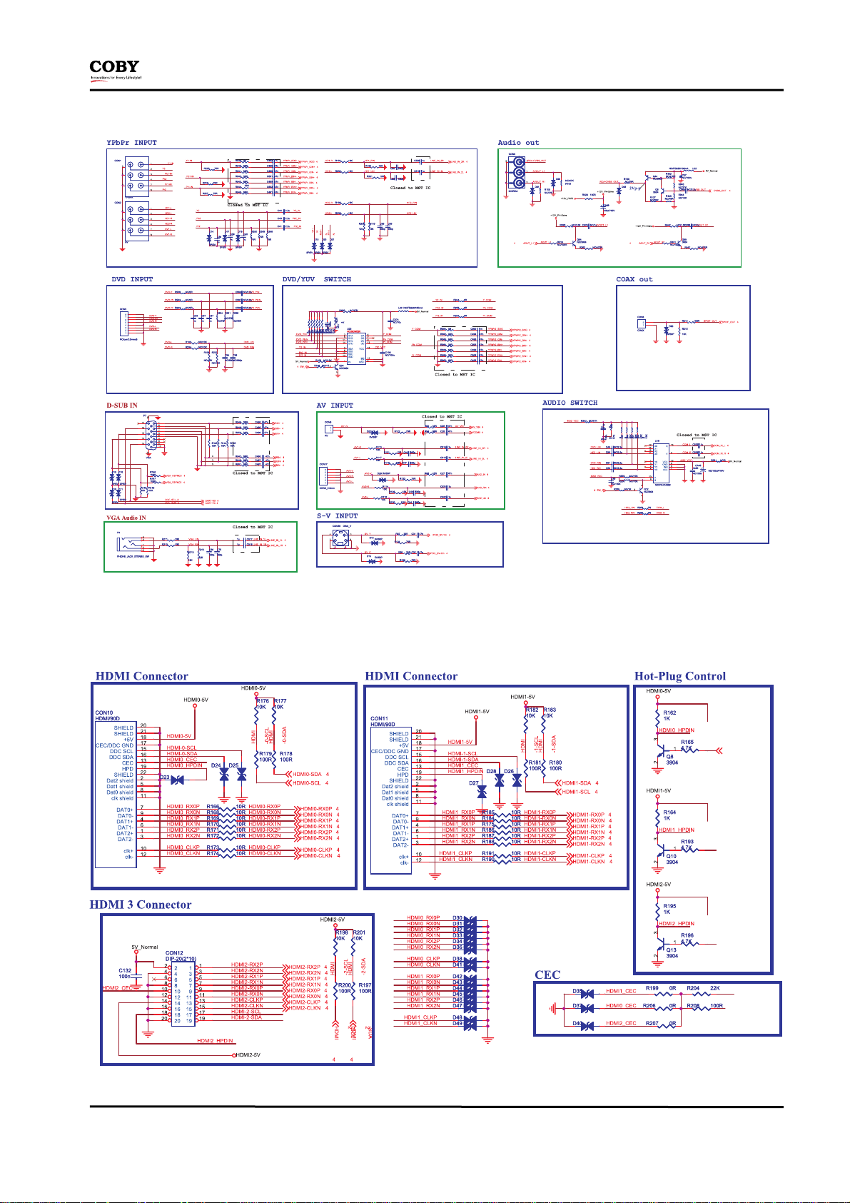
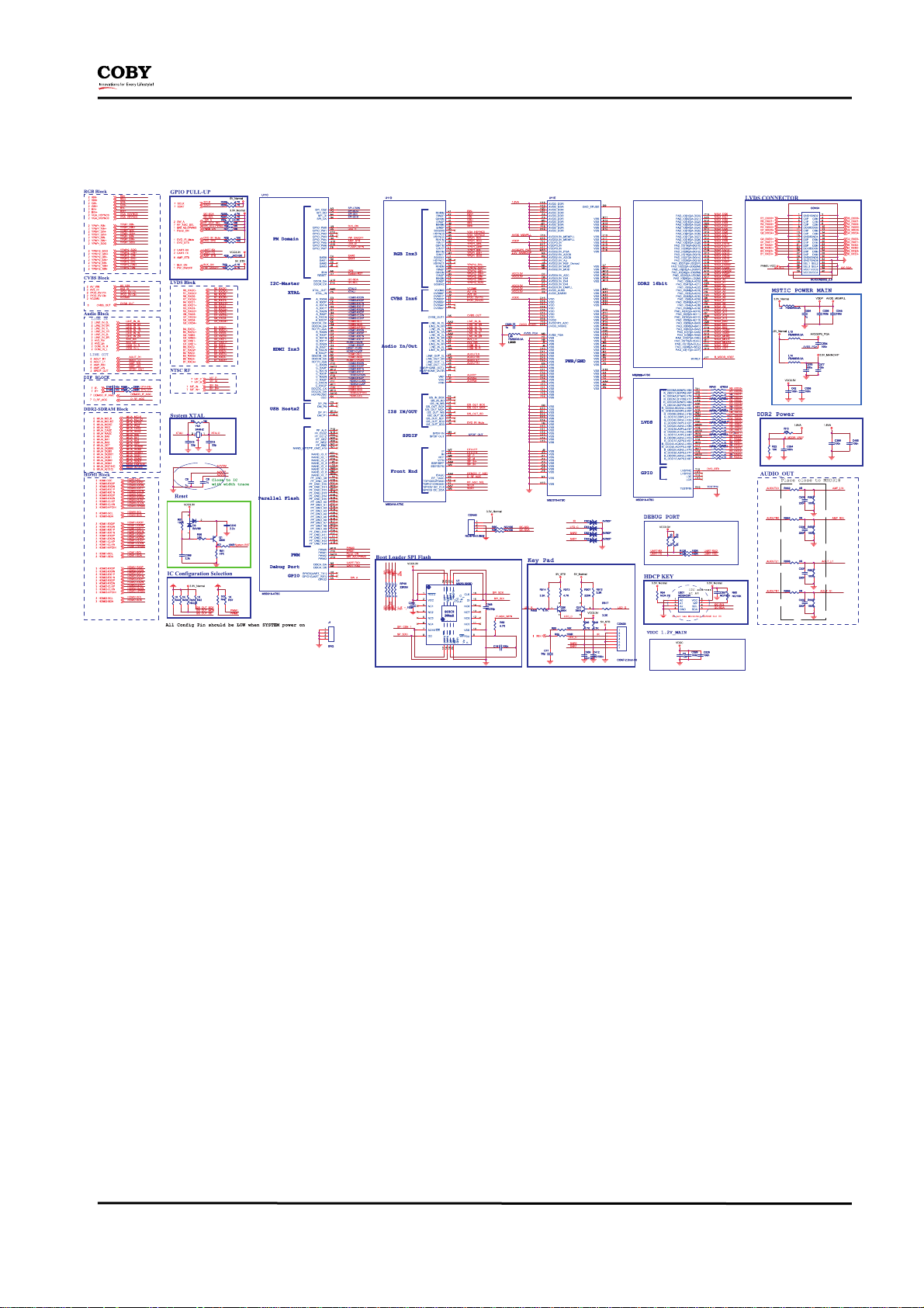
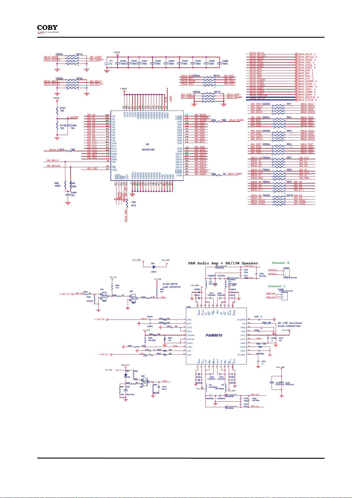
Schematic
Sep. 30th, 2010 (Version 1.3) Page 14 / 21
Page 15
Service Manual
Sep. 30th, 2010 (Version 1.3) Page 15 / 21
Page 16
Service Manual
Sep. 30th, 2010 (Version 1.3) Page 16 / 21
Page 17
Service Manual
Sep. 30th, 2010 (Version 1.3) Page 17 / 21
Page 18
Service Manual
Sep. 30th, 2010 (Version 1.3) Page 18 / 21
Page 19

Service Manual
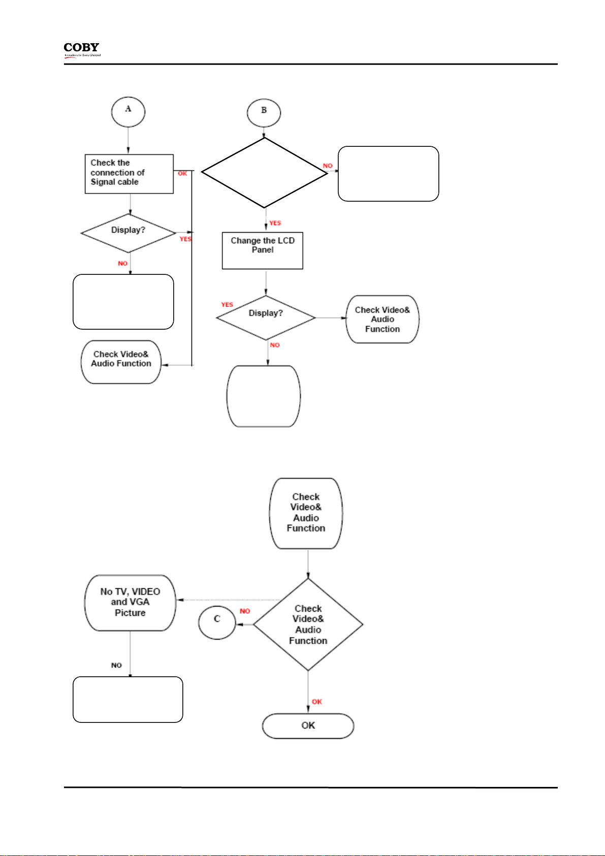
Trouble Shooting Flow Chart
Step 1
LED LIGHT ON?
LED brightness
variations
Check IR/LED
board high
Check the main board CON
33 PIN SAR0 SAR1 and IR
PIN
SAR0 Low?
Check Inverter Power
of LCD Panel, OK?
Sep. 30th, 2010 (Version 1.3) Page 19 / 21
Page 20
Service Manual
Change main Board
CON-PIN4 High
(See Panel SPEC)
Change main Board
Change
main
Board
Step 2
Change
Main Board
Sep. 30th, 2010 (Version 1.3) Page 20 / 21
Page 21
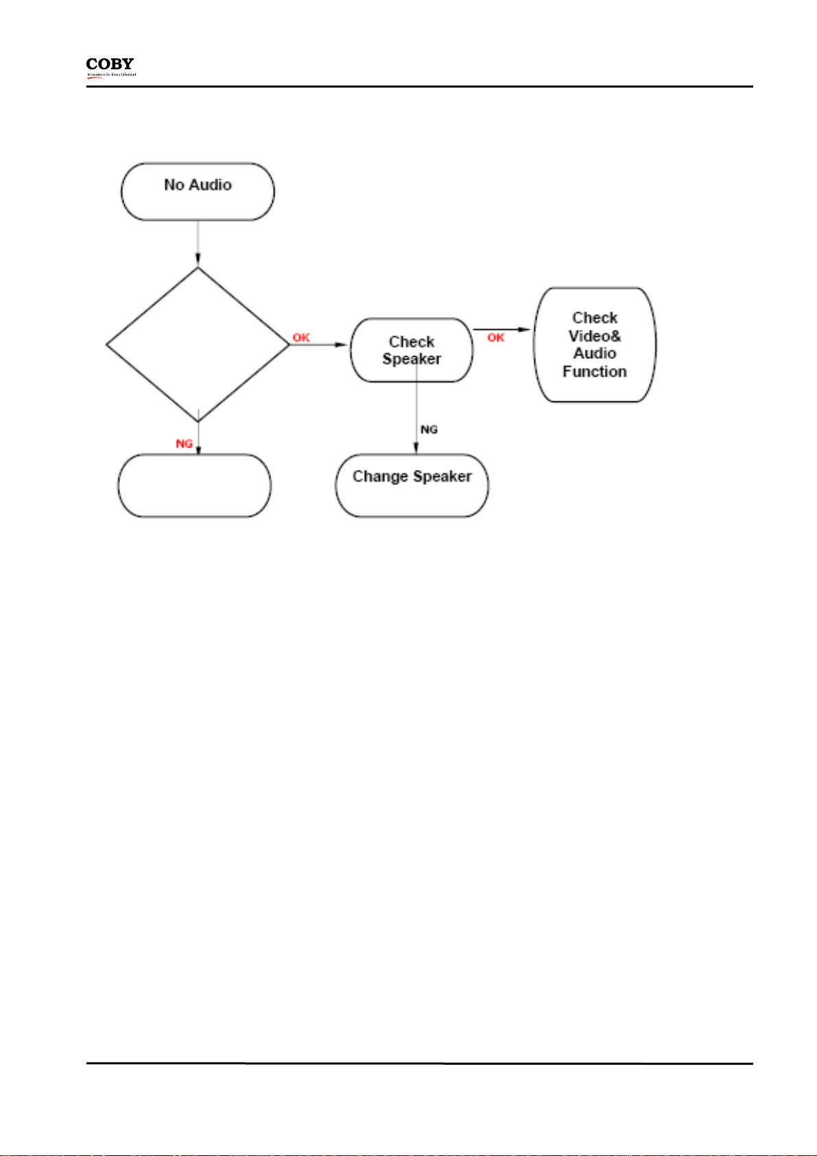
Step 3
Service Manual
Check Main board
CON37/CON38
Change Main
Board or U202
Sep. 30th, 2010 (Version 1.3) Page 21 / 21
 Loading...