

ATSC High-Denition (HD) Set Top Box
DTV-140
Instruction Manual
Please read this manual carefully before operation
www.cobyusa.com Page 3
PRECAUTIONS
For Customer Use:
Enter below the serial number that is located on the
unit. Retain this information for future reference.
Model No. DTV-140
Serial No.
The lightning ash with arrowhead symbol within an equilateral triangle is intended to aler t
the user to the presence of uninsulated “dangerous voltage” within the product’s enclosure
that may be of sufcient magnitude to c onstitute a risk of electric shock.
The exclamation point within an equilateral triangle is intended to alert the user to the presence of important operation and servicing instructions in the literature accompanying the
applianc e.
WARNING:
To prevent re or shock hazard, do not expose this device to rain or moisture. Dangerous high voltage is present
inside the enclosure. Do not open the c abinet.
CAUTION:
Any changes or modications not expressly approved in this manual could void your authority to operate this
equipment.
CAUTION:
These servicing instructions are for use by qualied service personnel only. To reduce the risk of electric shock,
do not per form any servicing other than that contained in the operating instructions unless you are qualied to
do so. Refer to manual for ser vicing instructions.
CAUTION:
Insert the power plug into the wall outlet with AC90-260V, 50/60 HZ. If you have difculty inser ting the plug, turn
it over and reinsert it. If the unit will not be used for a long time, disc onnect the plug from the outlet.
NOTICE:
Unauthorized copying, broadcasting, public per formance, and lending of disks are prohibited. This product incorporates copyright protection technology that is protected by method claims of certain U.S. patents and other
intellectual propert y rights owned by Macrovision Corporation and other r ights owners. Use of this copyright
protection technology must be authorized by Macrovision Corporation, and is intended for home and other
limited viewing uses only unless otherwise authorized by Macrovision Corporation. Reverse engineering or
disassembly is prohibited.
For recycling or disposal information about this product, please contact
your local authorities or the Electronics Industries Alliance:
www.eiae.org.
Page 2 Coby Electronics Corporation www.cobyusa.com Page 3
IMPORTANT SAFETY INSTRUCTIONS
Read Instructions: All the safety and operating instructions should be read before the prod-
1.
uct is operated.
Retain Instructions: The safety and operating instructions should be retained for future
2.
reference.
Heed Warnings: All warnings on the product and in the operating instructions should be
3.
adhered to.
Follow Instructions: All operating and usage instructions should be followed.
4.
Cleaning: For your safety, always unplug this product from the wall outlet before cleaning.
5.
Do not use liquid cleaners or aerosol cleaners. Use a dry or slightly damp (not wet) cloth for
cleaning or dusting.
Attachments: Use only attachments recommended by the manufacturer. Use of other at-
6.
tachments may be hazardous.
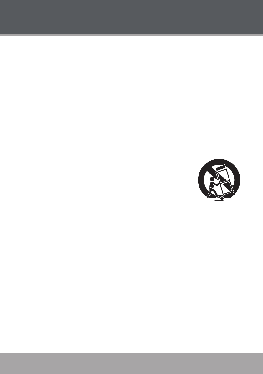
Accessories: Do not place this product on an unstable cart, stand, tripod,
7.
bracket, or table. Use only with carts, stands, tripods, brackets, or tables
recommended by the manufacturer or sold with the product. Any mount-
ing of the product should follow the manufacturer’s instructions and
should use a mounting accessory recommended by the manufacturer.
A product and car t combination should be moved with care. Quick
8.
stops, excessive force, and uneven surfaces may cause the product
and cart combination to overturn.
Water and Moisture: Water is a natural conductor of electricity. To avoid the possibility of
9.
shock or severe injury, do not use this product in or near any sources of water (e.g., a bath
tub, washbowl, kitchen sink, laundry tub, in wet basements, a swimming pool and the like).
Object and Liquid Entr y: Never push objects of any kind into this product, through openings
10.
or otherwise; this may result in objects touching dangerous voltage points or shor t-out parts
that could result in a personal or property damage or injur y, including re or electric shock.
Never spill liquid of any kind on the product.
Ventilation: Any electrically powered consumer electronic product generates heat while in
11.
use, thereby requiring proper ventilation. To ensure reliable operation of the product and to
protect it from overheating, do not operate the product on a bed, sofa, rug, or other similar
soft sur face, and never block any ventilation slots or openings provided for the unit. This
product should not be operated in any enclosed area such as a cabinet, bookcase or rack
unless proper ventilation is provided for the unit.
Heat: The product should be situated away from any heat sources such as radiators, heat
12.
registers, stoves, or other products (including ampliers) that produce heat.
Power Sources: This product should be operated only from the type of power source indi-
13.
cated on the rating label. If you are not sure of the type of power supply to your home, consult
your product dealer or local power company. For products intended to operate from battery
power or other sources, refer to the operating instructions.
www.cobyusa.com Page 3
www.cobyusa.com Page 5
IMPORTANT SAFETY INSTRUCTIONS
Grounding or Polarization: This product may be equipped with a polarized alternating-
14.
current line plug that has one blade wider than the other. This plug will only t into the power
outlet in one direction. This is a safety feature. If you are unable to insert the plug fully into the
outlet, try reversing the direction of the plug. If the plug should still fail to t, your outlet may
be obsolete; contact a licensed electrician to replace it. Never attempt to defeat the safety
purpose of the polarized plug.
Power-Cord Protection: Care must be taken to ensure that power supply cords are routed
15.
so as to avoid being damaged, such as by being walked on or pinched by items placed upon
or against them. You should pay particular attention to cords at plugs, convenience receptacles, and at the point where they exit from the product.
Protective Attachment Plug: The product may be equipped with an attachment plug with
16.
overload protection. This is a safety feature. See the operating instructions for replacement
or directions to reset the protective device. If replacement of the plug is required, please
consult an authorized service technician, and make sure s/he has used a replacement plug
that has the same overload protection as the original plug as specied by the manufacturer.
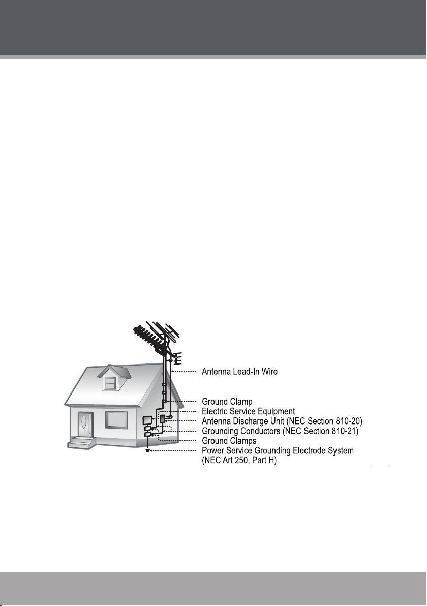
Outdoor Antenna Grounding: If an outside antenna is connected to the product, be sure
17.
the antenna system is grounded so as to provide some protection against voltage surges and
built-up static charges. Ar ticle 810 of the National Electrical Code, ANS/NFPA 70 provides
information with regard to proper grounding of the mast and supporting structure, grounding of the lead-in wire to an antenna-discharge unit, size of grounding conductors, location
of antenna-discharge unit, connection to grounding electrodes, and requirements for the
grounding electrode (see gure).
Lightning: Lightning can cause power surges, which may damage or destroy your product.
18.
For added protection, unplug it from the wall outlet and disconnect the antenna or cable system during a lightning storm or when it is left unattended and unused for long periods of time.
Power Lines: An outside antenna system should not be located in the vicinity of overhead
power lines or other electric light or power circuits, or where it can fall into such power lines
or circuits. When installing an outside antenna system, extreme care should be taken to keep
from touching such power lines or circuits, as contact with them might be fatal.
Page 4 Coby Electronics Corporation www.cobyusa.com Page 5

IMPORTANT SAFETY INSTRUCTIONS
Overloading: Always operate any electrical device in accordance with applicable electrical
19.
codes. Never overload wall outlets, extension cords, or integral convenience receptacles
as this can result in a risk of personal or property damage or injury, including re or electric
shock.
Servicing: Do not attempt to service this product yourself as opening or removing covers
20.
may expose you to dangerous voltage or other hazards, including the risk of injury or damage to persons or property. Your warranty will also be voided. Refer all servicing to qualied
service personnel.
Damage Requiring Service: Unplug this product from the wall outlet and refer servicing to
21.
qualied service personnel if: a) the power-supply or plug is damaged in any way; b) liquid
has been spilled or if objects have fallen or been introduced into the product; c) the product
has been exposed to rain, water or other sources of moisture; d) the product does not operate
normally by following the operating instructions. Adjust only those controls that are covered
by the operating instructions as improper adjustment of other controls may result in damage
and/or require extensive work by a qualied service technician to restore the product to its
normal operation; e) the product has been dropped or damaged in any way; f) the product
exhibits a distinct change in performance indicative of a need for ser vice.
Replacement Parts: When replacement parts are required, be sure that your service techni-
22.
cian has used replacement par ts specied by the manufacturer or have the same characteristics as the original par t. Unauthorized substitutions may result in injury to property or
persons including the risk of re, electric shock, or other hazards, and your warranty will be
voided.
Safety Check: Upon completion of any service or repairs to this product, ask the service
23.
technician to perform appropriate safety checks to ensure that the product is in proper operating condition.
Wall or Ceiling Mounting: the product should only be mounted to a wall or ceiling only as
24.
recommended in this Manual.
www.cobyusa.com Page 5

www.cobyusa.com Page 7
TABLE OF CONTENTS
PRECAUTIONS ..................................................................................................2
IMPORTANT SAFETY INSTRUCTIONS ...............................................................3
TABLE OF CONTENTS .......................................................................................6
PACKAGE CONTENTS......................................................................................7
FEATURES .........................................................................................................8
CONTROLS AT A GLANCE ..............................................................................9
Front View ........................................................................................................9
Rear View .......................................................................................................10
Remote Control ............................................................................................. 11
CONNECTIONS .............................................................................................13
AC Power ....................................................................................................... 13
Antenna Input ............................................................................................... 13
Audio/Video Output Connections............................................................. 14
Composite Video or S-Video ................................................................14
Component Video ................................................................................. 15
Connecting Digital Audio to a Digital Receiver System ................... 16
USING THE DTV-140 .......................................................................................18
Getting Started ............................................................................................. 18
Basic Operations ...........................................................................................18
Changing Channels ..............................................................................18
Adjusting the Volume ............................................................................19
DTV-140 Options ............................................................................................ 19
SETUP MENU ...................................................................................................21
Working with the Setup Menu ..................................................................... 21
Channel Settings ........................................................................................... 21
Caption Settings ...........................................................................................23
System Settings .............................................................................................. 23
Lock Settings .................................................................................................. 24
SPECIFICATIONS ...........................................................................................26
TROUBLESHOOTING ......................................................................................27
Page 6 Coby Electronics Corporation www.cobyusa.com Page 7
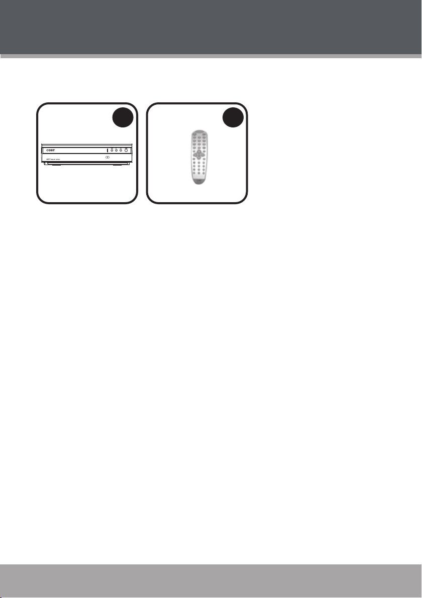
PACKAGE CONTENTS
1
2
Please make sure the following items are included in the product packaging. If
any items are missing, contact your local dealer.
DTV-140
1.
Remote Control
2.
www.cobyusa.com Page 7

www.cobyusa.com Page 9
FEATURES
Receives Free Over-the-Air (OTA) Digital Television Signals
•
Compatible with all 18 ATSC Signal Formats
•
Outputs OTA HDTV Signals for use with High-Denition TVs (720p/1080i)
•
Downconverts OTA HDTV Signals for use with Standard- and Enhanced-
•
Denition TVs (480i/480p)
On-Screen Program Guide
•
Page 8 Coby Electronics Corporation www.cobyusa.com Page 9
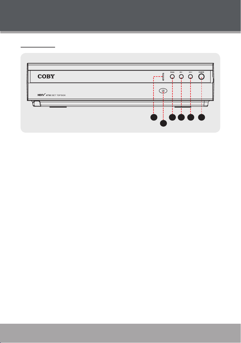
CONTROLS AT A GLANCE
1
324
5
6
Front View
Power Indicator
1.
Remote Control Sensor
2.
Scan
3.
Channel –
4.
Channel +
5.
Power
6.
www.cobyusa.com Page 9

www.cobyusa.com Page 11
Rear View
2
3
7
8
9
6
1
4
5
AC Power Cord
1.
Antenna In
2.
S-Video Out
3.
CONTROLS AT A GLANCE
Composite Video Out
4.
Stereo Audio Out (Composite Video)
5.
SPDIF Digital Audio Out
6.
Stereo Audio Out (Component Video)
7.
Component Video Out
8.
Serial Port (Service Only)
9.
Page 10 Coby Electronics Corporation www.cobyusa.com Page 11

CONTROLS AT A GLANCE
13
19
21
11
10
9
8
6
4
3
1
2
5
7
16
17
18
22
20
12
14
15
Remote Control
Power
1.
Source
2.
Numeric Keypad
3.
Recall
4.
Channel Input
5.
Menu
6.
Exit
7.
Navigation Keypad
8.
Up / Channel Up
Down / Channel Down
Right / Volume Up
Left / Volume Down
Enter
Closed Caption
9.
F1
10.
F2
11.
F3
12.
F4
13.
Information
14.
Mute
15.
Sleep
16.
Program Guide
17.
Favorites
18.
480i
19.
www.cobyusa.com Page 11
480p
20.
720p
21.
1080i
22.

www.cobyusa.com Page 13
CONTROLS AT A GLANCE
The remote control transmits a directional infrared beam. Be sure to aim the
remote control directly at the infrared remote sensor during operation. The sensor may not be able to receive signals properly if the sensor is covered, if there
is a large object between the remote control and the sensor, or if it is exposed
to direct sunlight or a strong articial light (e.g., uorescent or strobe lights). In
this case, change the direction of the light or reposition the unit to avoid direct
lighting.
To use the remote, point it at the remote sensor of the player. Operate the
•
remote within 15 feet of the sensor and at an angle of ± 60 degrees.
To install batteries in the remote
•
control, refer to the diagram. Remove the battery compartment
cover located on the rear of the
remote control. Insert batteries,
making sure to match their polarities (+/-) to the markings on the in-
side of the compartment. Replace
the cover.
Batteries in the remote will last for
•
approximately 1 year. Replace the
batteries if the remote control does
not work. Do not mix old with new
batteries, or different types of bat-
teries.
Remove the batteries from the re-
•
mote if it will not be used for a long
period of time.
Thebatteriesusedintheremotecontrolmaypresentareorchemical
burn if mistreated. Do not recharge, disassemble, incinerate, or heat
the battery (~212ºF).
Keep batteries away from children.
Page 12 Coby Electronics Corporation www.cobyusa.com Page 13

CONNECTIONS
DTV-140
Coaxial Cable (not supplied)
AC Power
Plug the AC power cord into an AC 90-260V 50/60 Hz wall outlet, only. If you
have difculty inserting the plug, turn it over and reinsert it.
Do not connect the power plug to a power outlet other than that which
isindicatedhereandonthelabelasthismayresultintheriskofreor
electric shock.
Do not handle the power plug with wet hands. Doing so may cause
electric shock.
Complete all system connections before connecting the power.
If the player will not be in use for a long period of time, turn the player
off, unplug the player, and remove any batteries, as applicable.
When disconnecting the AC power cord (mains lead), grasp the plug
itself and not the cord.
Antenna Input
Connect an antenna to the DTV-140 Antenna In jack to receive free, over-the-
air digital TV broadcasts.
The type of antenna used should be based upon your geographic loca-
tion, and should be aimed towards your local DTV broadcast stations
for best results. Please visit the website www.antennaweb.org for more
information about antenna types and station locations.
www.cobyusa.com Page 13

www.cobyusa.com Page 15
CONNECTIONS
AV Input Panel of TelevisionDTV-140
AV Cable
S-Video Cable
YELLOW
RED
WHITE
Audio/Video Output Connections
There are various connection options depending on your TV or other equipment; please refer to the documentation supplied by the manufacturer of your
TV or stereo system for more connection information as necessary.
Composite Video or S-Video
The DTV-140 can output video signals up to 480p over Composite Video or S-
Video. If your television has Composite Video or S-Video input jacks:
Make the video connection. Choose only one of the following video con-
1.
nection types:
Composite Video: Using a Composite Video AV patch cable, connect the
•
unit’s Composite Video Out jack to the Video In jack (yellow) of your TV.
S-Video: Using an optional S-Video cable, connect the unit’s S-Video Out
•
jack to the S-Video In jack of your TV.
Make the audio connection. Using a Composite Video AV patch cable,
2.
connect the unit’s Stereo Audio Out (Composite Video) jacks to the Audio
In jacks (red and white) of your TV.
Page 14 Coby Electronics Corporation www.cobyusa.com Page 15

AV Input Panel of Television
DTV-140
Component Cable
AV Cable
GREEN
WHITE
YELLOW
(unused)
YELLOW
(unused)
RED
RED
BLUE
Y Pb Pr
CONNECTIONS
Component Video
The DTV-140 can output video signals up to 1080i over Component Video. If
your television has Component Video jacks:
Make the video connection.
1.
Component Video: Using an optional component video cable, connect
•
the unit’s Component Video Out jacks (Y/Pb/Pr) to the Component Video
In jacks (Green/Blue/Red) of your TV.
Make the audio connection. Using the supplied AV patch cable, connect
2.
the unit’s Stereo Audio Out (Component Video) jacks to the Audio In
jacks (red and white) of your TV. The yellow connector of the AV cable is
unused.
www.cobyusa.com Page 15

www.cobyusa.com Page 17
Audio Input Panel of
Receiver/Amplifier
DTV-140
SPDIF Coaxial Digital Audio Cable
SPDIF DIGITAL
AUDIO INPUT
CONNECTIONS
Connecting Digital Audio to a Digital Receiver System
The DTV-140 can output digital 5.1-channel digital audio signals over SPDIF
Digital Audio. If you have a digital decoding receiver system with an SPDIF Digital Audio jack:
Make the audio connection. Using an optional coaxial digital audio cable,
•
connect the unit’s SPDIF Digital Audio Out jack to the Digital Audio Input
jack of your receiver.
Combine the digital audio connection with any video connection for a
complete audio/video experience.
To avoid signal interference, use only one audio connection type at a
time.
Digital Audio can be output in two formats: Raw or PCM. For more in-
formation, please refer to your receiver’s documentation.
Page 16 Coby Electronics Corporation www.cobyusa.com Page 17

USING THE DTV-140
Getting Started
All keypress information refers to the remote control unless the instructions
indicate otherwise.
Prepare the connections and power supply (see the Connections section
1.
of this manual for more information).
Press to turn the unit on.
2.
Set your TV to display the video line connection that corresponds to
3.
the DTV-140 (e.g., AV1, AV2, S-Video, Component, etc.) The DTV-140
output will be displayed on the TV screen when the proper line has been
selected.
Press the SCAN button on the front panel to automatically search for and
4.
store all channels within broadcast reception range.
It is only necessary to scan for channels upon initial use. See the Setup
section of this manual to edit the stored channel list.
Basic Operations
Changing Channels
Press the Channel Up or Channel Down buttons on the front panel of the unit,
or use the remote control.
Channel Functions Remote Key
Change the channel up.
Change the channel down.
Initiate direct channel access. After pressing , use the nu-
meric keypad to enter a channel number to change to.
Return to a previous channel.
Access the Favorite Channels list. To learn how to add channels to
the list, refer to the Setup Menu section of this manual.
www.cobyusa.com Page 17

www.cobyusa.com Page 19
USING THE DTV-140
Channel Functions Remote Key
View channel information.
View the Electronic Program Guide.
Adjusting the Volume
You can adjust the volume output level of the DTV-140. You may also choose to
adjust the volume using the controls of your TV or receiver system.
Volume Functions Remote Key
Increase the volume output level.
Decrease the volume output level.
Disable all audio output. Press again to restore audio output.
DTV-140 Options
Some of the more commonly used options may be changed by using the remote
control. For more option settings, refer to the Setup Menu section of this manual.
Option Functions Remote Key
Change the DTV signal source: STD, HRC, IRC, or AIR.
Change the DTV video signal resolution to 480i. Use this resolution
with Standard Denition TVs (SDTVs).
Change the DTV video signal resolution to 480p. Use this resolu-
tion with Enhanced Denition TVs (EDTVs).
Change the DTV video signal resolution to 720p. Use this resolution
with High Denition TVs (HDTVs) that are 720p capable.
Change the DTV video signal resolution to 1080i. Use this resolu-
tion with High Denition TVs (HDTVs) that are 1080i capable.
Change the Closed-Caption options: CC OFF, CC ON, or
CC ON-MUTE.
Change the font style of the Closed-Caption display.
Page 18 Coby Electronics Corporation www.cobyusa.com Page 19

USING THE DTV-140
Option Functions Remote Key
Change the font size of the Closed-Caption display.
Change the foreground color of the Closed-Caption display.
Change the background color of the Closed-Caption display.
Set the Sleep Timer (in minutes): 30, 60, 90, 120, or Off. The timer
will turn the unit off automatically.
When the Sleep Timer is set, press again to view the
elapsed time.
Access the Setup menu.
Exit the Setup menu.
www.cobyusa.com Page 19

www.cobyusa.com Page 21
SETUP MENU
Channel LockCaption Setup
DTV Source
Caption
Analog CC
Digital CC
Auto Scan
Edit Channels
DTV Signal
Working with the Setup Menu
Enter Menu mode to adjust the various internal settings of the unit.
Press to enter Menu mode. The Setup Menu will appear.
1.
Use the Navigation Keypad [ ] to select a desired item:
2.
Press to conrm a selection.
•
Press or to cancel and return to the previous item.
•
Press to exit Menu mode.
3.
Channel Settings
Use the Navigation Keypad to highlight the desired channel setting and press
to conrm.
Channel Setting Description
DTV Source Set the DTV signal source: Air, STD, HRC, IRC.
Caption Turn the closed caption feature on or off.
Analog CC
Digital CC Set the digital closed caption source: Service 1 – Service 6.
Page 20 Coby Electronics Corporation www.cobyusa.com Page 21
Set the analog closed caption source:
CC, CC1, CC2, CC3, CC4.

SETUP MENU
ChanNo Channel Name Fav. Skip
Edit Channels
00-1
Channel Setting Description
Automatically search for and store all channels within broad-
Auto Scan
Edit Channels
cast reception range. This function may also be enabled by
pressing the SCAN button on the front panel of the unit.
Upon selecting “Edit Channels”, the following screen will appear:
If the Auto Scan function was used previously, the Channel
List will be lled with any channels that were found within
reception range.
To save a Channel No. as “Favorite”, use the Navigation
•
Keypad to select FAV and press . A check mark will
appear to indicate that the channel has been saved as
a Favorite channel.
To remove a Channel No., use the Navigation Keypad to
•
DTV Signal
www.cobyusa.com Page 21
select SKIP and press .
View DTV signal information.
•
Access a specic channel directly.
•

www.cobyusa.com Page 23
SETUP MENU
Caption Settings
Use the Navigation Keypad to highlight the desired caption setting and press
to conrm.
Caption Setting Description
Font Style Set the Closed Caption font style.
Font Size Set the Closed Caption font size.
Foreground Color Set the Closed Caption foreground color.
Background Color Set the Closed Caption background color.
Foreground Opacity Set the Closed Caption foreground to be solid or transparent.
Background Opacity Set the Closed Caption background solid or transparent.
System Settings
Use the Navigation Keypad to highlight the desired system setting and press
to conrm.
System Setting Description
Picture Size Set the Aspect ratio of the display: Auto, 16:9 (widescreen).
Language Set the menu display language: English, Spanish, French.
Time Zone Set the Time Zone: Pacic, Mountain, Central, Eastern.
Sleep Timer Set the Sleep Timer (in minutes): 30, 60, 90, 120 or OFF.
About View COBY copyright information.
Page 22 Coby Electronics Corporation www.cobyusa.com Page 23

SETUP MENU
Lock Settings
Use the Navigation Keypad to highlight the desired Lock setting and press to
conrm. A password prompt will appear; you must enter the correct password to
access the Lock Settings.
Use the Numeric Keypad to enter the 4-digit password. Upon entering the
•
correct password, the Lock Setting options will appear.
The initial password is “0000”. After entering the password, you may use
•
the “Change PIN” setting to change the password.
Resetting the unit to its default settings will not reset the password. DO
NOT FORGET THE PASSWORD; write the password down and store
it somewhere safe.
Lock Setting Description
Movie broadcasts that have been classied with a higher rating will be blocked.
NA: no restrictions (lowest rating)
•
G: General Audience
•
PG: Parental Guidance suggested
MPAA
CanEnglish
CanFrench
•
PG-13: Not intended for ages under 13
•
R: Restricted
•
NC-17: Not intended for ages under 17
•
X: For adults only (highest rating).
•
Canadian English broadcasts that have been classied with a
higher rating will be blocked. NA, C, C8+, G, PG, 14+, 18+.
NA is the lowest rating, 18+ is the highest rating.•
Canadian French broadcasts that have been classied with
a higher rating will be blocked. NA, G, 8ANS+, 13ANS+,
16ANS+, 18ANS+.
NA is the lowest rating, 18ANS+ is the highest rating.•
www.cobyusa.com Page 23

www.cobyusa.com Page 25
SETUP MENU
Lock Setting Description
TV broadcasts that have been classied with a higher rating
will be blocked.
None/Off: no restrictions (lowest rating)
•
TV-Y: All children
•
TV-Y7: For children aged 7 and above
TV Guidelines
Change PIN
V-Chip Ctrl Turn the Lock features on or off.
•
TV-G: General Audience
•
TV-PG: Parental Guidance suggested
•
TV-14: Not intended for ages under 14
•
TV-MA: For mature audiences only (highest rating).
•
Enter the old password, the new password, and then the new
password again to verify and change the Parental Settings
password. Restoring the player’s default settings will not reset
the password. DO NOT FORGET THE PASSWORD; this
password cannot be reset.
Page 24 Coby Electronics Corporation www.cobyusa.com Page 25

SPECIFICATIONS
TV System ATSC
Channel Coverage VHF-L: 57MHZ ~ 129MHz
VHF-H: 135MHZ ~ 363 MHz
UHF: 369 ~ 803MHz
Video Output Component Video
S-Video
Composite Video
Audio Output Coaxial Digital Audio
RCA 2-Channel Stereo Audio
Operating Temperature
Power AC 90-260V 50/60Hz
Unit Dimensions 123 x 78 x 28 mm
Weight 177g
50ºF – 104ºF
10W (max)
Specicationsandmanualaresubjecttochangewithoutnotice.
www.cobyusa.com Page 25

www.cobyusa.com Page 27
TROUBLESHOOTING
If you have a problem with this player, please read the troubleshooting guide
below and check our website at www.cobyusa.com for Frequently Asked
Questions (FAQs) and rmware updates. If these resources do not resolve the
problem, please contact Technical Support.
COBY Electronics Technical Support
56-65 Rust Street
Maspeth, NY 11378
Hours: 8:00 AM–11:00 PM EST, seven days a week.
Email: techsupport@cobyusa.com
Phone: 718-416-3197, 800-681-2629, or 800-727-3592
Web: www.cobyusa.com
There is no power to the device.
Ensure that the AC adapter cord is securely connected to the player and the
•
proper wall outlet.
Ensure that the Power Switch on the main unit has been set to the ON
•
position.
There is no picture.
Try another TV channel
•
Check if the system connections are proper and secure.
•
Check if the connection cables are damaged.
•
The picture color is distorted.
Reset the color system of the unit.
•
Check if the system has been properly connected.
•
Check if the AV video signal input cable is connected properly.
•
Page 26 Coby Electronics Corporation www.cobyusa.com Page 27

TROUBLESHOOTING
The picture is not full-screen.
Change the aspect ratio setting (Picture Size) of the unit from the Setup
•
menu.
Change the aspect ratio setting of your TV.
•
There is no sound or distorted sound.
Increase the volume.
•
Check if the sound system has been properly set.
•
Check if the AV audio signal input cable has been connected properly.
•
The picture and sound are distorted.
Check if the system has been properly connected.
•
Adjust the position of the antenna.
•
The remote control doesn’t work.
Ensure that the Power Switch has been physically set to the ON position.
•
Ensure that there are no obstacles between the remote and the player.
•
Point the remote at the remote sensor on the main unit.
•
Ensure that the batteries in the remote retain a charge and have been
•
installed correctly.
Try replacing the remote’s batteries.
•
The unit has malfunctioned.
Unplug the unit. After 30 minutes, plug in and power on the unit—the
•
restore function should reset the player.
www.cobyusa.com Page 27

COBY Electronics Corp.
56- 65 Rust Street
Maspeth, NY 11378
ww w.cobyusa.com
ww w.ecoby.com
 Loading...