

Page 1

Read this manual carefully to get the best performance from 2.1 System
2.4GHz DIGITAL WIRELESS SOUNDBAR SYSTEM
CSMP95
OWNER`S MANUAL
Page 2
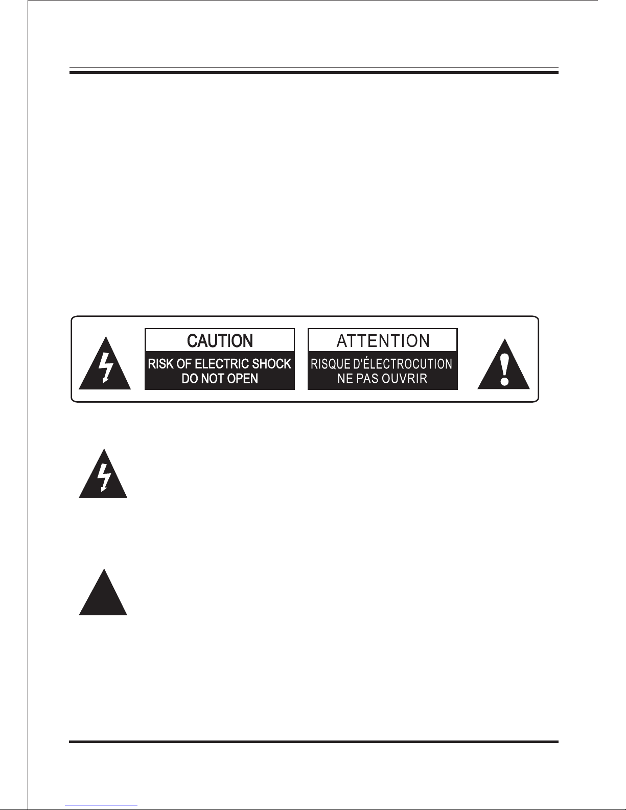
WARNINGS AND PRECAUTIONS
!
The lightning flash with arrowhead symbol, within an equilateral
triangle, is intended to alert the user to the presence of uninsulated
"dangerous voltage" within the product's enclosure that may be of
sufficient magnitude to constitute a risk of electric shock to persons.
This symbol is intended to alert the user to the presence of important
operation and maintenance (servicing) instructions in the literature
accompanying the appliance.
1
WARNING:
To reduce the risk of fire or electric shock, do not expose this apparatus to
rain or moisture.
The apparatus shall not be exposed to dripping or splashing and that no
objects filled with liquids, such as vases, shall be placed on apparatus.
WARNING:
To reduce the risk of electric shock, do not remove cover (or back).
Page 3

FCC STATEMENT
FCC STATEMENT
1. This device complies with Part 15 of the FCC Rules. Operation is subject
to the following two conditions:
(1) This device may not cause harmful interference.
(2) This device must accept any interference received, including
interference that may cause undesired operation.
2. Changes or modifications not expressly approved by the party responsible
for compliance could void the user's authority to operate the equipment.
NOTE: This equipment has been tested and found to comply with the limits
for a Class B digital device, pursuant to Part 15 of the FCC Rules.
These limits are designed to provide reasonable protection against harmful
interference in a residential installation. This equipment generates uses and
can radiate radio frequency energy and, if not installed and used in
accordance with the instructions, may cause harmful interference to radio
communications. However, there is no guarantee that interference will not
occur in a particular installation. If this equipment does cause harmful
interference to radio or television reception, which can be determined by
turning the equipment off and on, the user is encouraged to try to correct the
interference by one or more of the following measures:
Reorient or relocate the receiving antenna.
Increase the separation between the equipment and receiver.
Connect the equipment into an outlet on a circuit different from that to
which the receiver is connected.
Consult the dealer or an experienced radio/TV technician for help.
2
Page 4

Caution: Please read carefully all the following important safeguards to en-
sure safe operation.
1. Read these Instructions.
2. Keep these Instructions.
3. Heed all Warnings.
4. Follow all instructions.
5. Do not use this apparatus near water.
6. Clean only with a dry cloth.
7. Do not block any ventilation openings. Install in accordance with the
manufacturer's instructions.
8. Do not install near any heat sources such as radiators, heat registers, stoves,
or other apparatus (including amplifiers) that produce heat.
9. Do not defeat the safety purpose of the polarized or grounding - type plug.
A polarized plug has two blades with one wider than the other. When the
provided plug does not fit into your outlet, consult an electrician for
replacement of the obsolete outlet.
10. Protect the power cord from being walked on or pinched particularly at plugs,
convenience receptacles, and the point where they exit from the apparatus.
11. Only use attachments/accessories specified by the manufacturer.
12. Use only with a cart, stand, tripod, bracket, or table specified
by the manufacturer, or sold with the apparatus. When a
cart or rack is used,use caution when moving the cart/
apparatus, combination to avoid injury from tip-over.
IMPORTANT SAFETY INSTRUCTIONS
3
Page 5

4
IMPORTANT SAFETY INSTRUCTIONS
13. Unplug this apparatus during lightning storms or when unused for long
periods of time.
14. Refer all servicing to qualified service personnel. Servicing is required when
the apparatus has been damaged in any way, such as power-supply cord or plug
is damaged, liquid has been spilled or objects have fallen into the apparatus,
the apparatus has been exposed to rain or moisture, does not operate normally,
or has been dropped.
15. WARNING: The mains plug (appliance coupler) is used as disconnect device,
the disconnect device shall remain readily operable.
16. The battery (battery or batteries or battery pack) shall not be exposed to
excessive heat such as sunshine, fire or the like.
17. No naked flame sources, such as lighted candles, should be placed on the
apparatus.
18. Label marking is located at the bottom of the apparatus.
19. This equipment is a Class II or double insulated electrical appliance. It has
been designed in such a way that it does not require a safety connection to
electrical earth.
Contents:
- Remote Control x 1 - S x 8
- Wall mounting brackets x 2 - W x 2
- RCA to RCA x 1 - RCA to 3.5mm x 1
- Coaxial Cable x 1 - A x 8
- User's Manual x 1 - Installation Guide x 1
crew
all mounting screw
ssembling bolt
PARTS LIST
Page 6

FRONT PANEL - CONTROLS AND FUNCTIONS
5
5. : Power Standby STANDBY Button.
1. Remote Sensor.
6.INPUT:Input Selection Button.
2. STANDBY:Standby Input Indicator.
8.VOL+: Volume Upward Adjustment Button.
7.VOL-: Volume Downward Adjustment Button.
1 2
3
4
5 6 7 8
3. TV:TV Input Indicator.
4. AUX/COAX:AUX and Coaxial Input Indicator.
Page 7

40 Watt + 2 x 20 Watt
AC 120V~60Hz
2.4GHz DIGITAL WIRELESS
SYSTEM
SOUNDBAR
MADE IN CHINA
CSMP95
FCC ID:xxxx xxx
This device complies with Part 15 of the FCC
Rules. Operation is subject to the following two
conditions: (1) this device may not cause harmful
interference, and (2)this device must accept any
interference received, including interference that
may cause undesired operation.
XXXXXXX
CONFORMS TO ANS I/UL STD .6006 5
CERTIFIED TO C AN/CS A STD.C2 2.2 No. 60065
6
3.AUX Stereo Audio Input.Right
4.AUX Stereo Audio Input.Left
REAR PANEL - CONTROLS AND FUNCTIONS
9
10
5.TV Stereo Audio Input.Right
6.TV Stereo Audio Input.Left
8
2
3
4
5
1
6
1.Power On/Off Switch.(Soundbar)
2.AC Power Cord.(Soundbar)
7
40 Wat t + 2 x 20 Watt
AC 12 0V~60 Hz
2.4 GHz DIG ITAL WIREL ESS
SYS TEM
SOU NDBAR
MAD E IN CHIN A
CSM P95
7. Audio Input.Coaxial
AC 120 V~60H z
XXX XXXX
CON FORMS TO AN SI/UL ST D.600 65
CERT IFIED T O CAN/C SA STD.C2 2.2 No. 60065
AC 12 0V~60 Hz
Page 8

REAR PANEL - CONTROLS AND FUNCTIONS
7
9.Power On/Off Switch.(Subwoofer)
10. AC Power Cord.(Subwoofer)
8.STANDBY:Subwoofer Standby Input Indicator.
SYSTEM CONNECTION INSTRUCTIONS
TV
Video In
Video Out
Rear-R
Center
Woofer
Rear-L
Front- L
Front- R
DVD Player
optional
Optical
Audio Out
Rear-R
Center
Woofer
Rear-L
Front-L
Coaxial
Front-R
Video Out
Scart out
Video
S-Video
U
VY
Manufactured under license from Dolby Laboratories.
"Doldy","Dolby Digital", and the double-D symbol are
trademarks of Dolby Laboratories. Confidential
Unpublished Works.
@1992-1997 Dolby Laboratories, Inc.
All rights reserved.
Apparatus Claims of U.S. Patent Nos.
4,631,603;4,577,216;4,819,098 and 4,907,093
licensed for limited viewing uses only.
RISK OF ELECTRIC SHOCK
DO NOT OPEN
WARNING
!
AC 100V~240V
50/60Hz
Video
RCA Cable
To Stereo Output
Audio Out
Page 9

REMOTE CONTROL
8
1. : Power Standby.STANDBY
4.VOL-: Volume Downward Adjustment Button.
8.MUTE: Mute Function Button .
2.MUSIC: Music Mode .Selection
3.NORMAL: Normal Mode .Selection
5.BASS-: Bass Downward Adjustment Button.
6.TREBLE-: Treble Downward Adjustment Button.
7. INPUT: Input . Selection Button
11
12
13
2
3
4
5
6
7
8
9
10
1
9.RESET: Location Retrieval Button .
10.MOVIE: M ovie Mode .Selection
11.VOL+: Volume Upward Adjustment Button.
12.BASS+: Bass Upward Adjustment Button.
13.TREBLE+: Treble Upward Adjustment Button.
Page 10

9
REMOTE CONTROL
1.Replace the remote control battery when it no longer operates the
unit, or the range is reduced considerably.
2.Use only CR2025 or CR2032 3V lithium batteries
3.Bear in mind that lighting & other room conditions, in addition to
battery age, can affect the operating range of an infrared remote control.
4.Battery disposal:
Batteries and rechargeable batteries are prohibited to dispose into
household waste.
REMOTE CONTROL BATTERY REPLACEMENT
CR2025
Page 11

10
SPEAKER PLACEMENT
PLACING THE SOUNDBAR ON A TABLE
If your TV is placed on a table, you can place the soundbar on the table directly
in front of the TV stand, centered with the TV screen.
As long as the surface of the table is flat, the soundbar will rest on its rubber
bumpers.
PLACING THE SUBWOOFER
The performance of a subwoofer is directly related to its placement in the listening
room and its physical position relative to the other speakers in the system.
While it is true that in general, our ears do not hear directional sounds at the law
frequencies where subwoofers operate, when installing a subwoofer within the
limited confines of a room, the reflections, standing waves and absorptions
generated within the room will strongly influence the performance of any
subwoofer system. As a result, the specific location of the subwoofer in the room
does become important to the amount and quality of bass that is produced.
Page 12

PLACING THE SUBWOOFER
11
For example, placing the subwoofer next to a wall generally will increase the
amount of bass in the room; placing it in a corner generally will maximize
amount of bass in the room. However, corner placement can also increase the
destructive effect of standing waves on bass performance. This effect can vary
depending on the listening position – some listening positions may yield very
good results, while others may have far too much (or too little) bass at certain
frequencies.
In many rooms, placing the subwoofer along the same plane as the soundbar can
produce the best integration between the sound of the subwoofer and that of the
left and right speakers. In some rooms, the best performance could even result
from placing the subwoofer behind the listening position .
We strongly recommend that you experiment with placement before choosing a
final location for your subwoofer. One way you can determine the best location
for the subwoofer is by temporarily placing it in the listening position and playing
music with strong bass content. Move around to various locations in the room
while the system is playing (putting your ears where the subwoofer would be
placed), and listen until you find the location where the bass performance is best.
Place the subwoofer in that location.
IMPORTANT: The maximum wireless operation distance between the soundbar
and subwoofer is approximately 50 feet (15.3m).
Page 13

A. Switch On/Off
1. Before turning on the system, please connect it according to
the System Connection Instruction.
2. Connect AC power supply with this product.
(Caution: Power source must be consistent with this product.)
3. Press on the POWER switch button on the Rear Panel of the main
unit to switch on the system, the standby indicator will light up.
Then press the STANDBY button on the remote controller to enter
the normal status. Press the button on the remote controller once
again to keep power in standby status.
B. VOLUME
1.Press the VOL + button on the front of the main unit, or the
VOL + button on the remote control to increase the volume.
2.Press the VOL - button on the front of the main unit, or the
VOL - button on the remote control to decrease the volume.
C. MUTE
1. Press the MUTE button on the remote controller once to
keep the performance silent.
Press the RESET button on the remote controller and it will reset
all settings including SW Speaker output, Front Speaker output to
factory default settings.
D. RESET
OPERATION
12
Page 14

13
WALL MOUNTING BRACKET INSTALLATION GUIDE
1.Take out the soundbar, paperboard, assembling bolt, bracket screw,
plastic wall mounting bracket and wall mounting screw.
2.Draw out the location of the holes for the screws by paperboard and
pencil, to confirm the location of the plastic wall mounting bracket.
Please make sure that the paperboard is horizontal and the height of the
soundbar is suitable for you.
3.Please drill 8 holes according to the location you drawed on the wall by
pencil.
4.Punch the assembling bolts into the holes on the wall.
5.Align the holes on plastic wall mounting bracket with the holes on
paperboard and wall, then fasten with 8 screws through the assembling
bolts.
6.Screw the two wall mounting screws on the rear panel of soundbar, then
you can hang up your soundbar on the middle holes of both plastic wall
mounting bracket easily.
Page 15

1.Power Supply.................................................................... AC 120V/60Hz
2.Total Power Consumption........................................................................80W
3.Input Sensitivity (Subwoofer).................................................200mV 20mV
4.Input Sensitivity (Soundbar)...................................................750mV 50mV
5.Speaker Impedance (Subwoofer)..........................................................8 Ohm
6.Speaker Impedance (Soundbar)............................................................8 Ohm
7.S/N (A Weight)........................................................................................80dB
8.Subwoofer Power Output ........................................................................40W
9.Soundbar Power Output ....................................................................2 x 20W
10.THD (1kHz, 1W)...................................................................................0.5%
11.Frequency Response..................................................... 20Hz~20KHz 3dB
12.L/R Separation (1kHz)..........................................................................30dB
13.L/R Balance (Stereo)........................................................................... 2dB
......
SPECIFICATIONS
Note: Specifications are subject to change for improvements.
14
Page 16

TROUB LES HOOTIN G
If you have a problem with this device, please read the troubleshooting guide below and
check our website at for Frequently Asked Questions (FAQs) and
firmware updates. If these resources do not resolve the problem, please contact Technical
Support.
www.cobyusa.com
Address
COBY Electronics Corporation
Technical Support
150 Knowlton Way
Savannah, GA 31407
Email
Web
Phone
800-727-3592: Weekdays: 8:30AM-9:00PM EST
Saturdays: 9:00AM-5:30PM EST
techsupport@cobyusa.com
www.cobyusa.com
 Loading...