

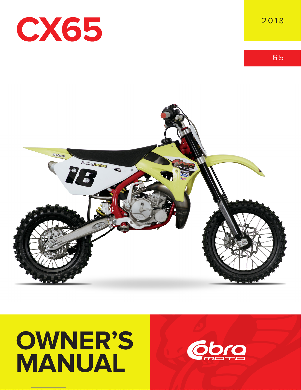
Cobra Moto CX65 Owner's Manual

For parts orders contact your local dealer
To locate your closest Cobra dealer
log on to
www.cobramoto.com
or call
(517) 437-9100
If you need technical assistance
contact your local dealer or call
the Cobra Technical Support Hotline at
(517) 437-9100
Cobra Moto, LLC
240 Uran Street
Hillsdale, Michigan 49242
1
DISCLAIMER OF WARRANTY
This motorcycle is sold “as is” with all faults, obvious or not. There are no warranties
expressed or implied, including any warranty of merchantability and warranty of fitness
for any particular purpose.
“WARNING”
THE COBRA CX65 IS A COMPETITION MODEL ONLY AND IS NOT
MANUFACTURED FOR, NOR SHOULD IT BE USED ON PUBLIC STREETS, ROADS
OR HIGHWAYS.
THE USE OF THIS BIKE SHOULD BE LIMITED TO PARTICIPATION IN
SANCTIONED COMPETITION EVENTS UPON A CLOSED COURSE BY A
SUFFICIENTLY SKILLED RIDER AND SHOULD NOT BE USED FOR GENERAL
OFF-ROAD RECREATIONAL RIDING.
IMPROPER USE OF THIS MOTORCYCLE CAN CAUSE INJURY OR DEATH.
THIS BIKE IS INTENDED FOR EXPERIENCED RACERS ONLY AND NOT FOR
BEGINNERS.
IT IS YOUR RESPONSIBILITY AS THE OWNER OF THIS COBRA MOTORCYCLE
OR AS THE PARENT, OR LEGAL GUARDIAN OF THE OPERATOR, TO KEEP THIS
COBRA MOTORCYCLE IN PROPER OPERATING CONDITION.
THIS BIKE WAS DESIGNED FOR RIDERS THAT WEIGH LESS THAN 110 LBS WITH
FULL RIDING GEAR AND SHOULD NOT BE OPERATED BY RIDERS THAT WEIGH
MORE THAN THAT.
BE SURE THAT THE RIDER ALWAYS WEARS ADEQUATE SAFETY GEAR
EVERYTIME HE OR SHE RIDES THEIR COBRA MOTORCYCLE.
IMPORTANT SAFETY NOTICE
Failure to follow WARNING instructions could result in severe injury or death to
the machine operator, a bystander, or a person inspecting or repairing the
machine.
CAUTION:
A CAUTION indicates special precautions that must be taken to avoid damage to
the machine.
NOTE:
A NOTE provides key information to make procedures easier or clearer.
MCC62018.1

2
Table of Contents
GENERAL INFORMATION ........................................................................................... 4
SPECIFICATIONS - GENERAL ................................................................................. 4
OPTIONAL COMPONENTS ...................................................................................... 5
SPECIFICATIONS - TORQUE VALUES ...................................................................... 5
BREAK-IN PROCEDURE ........................................................................................ 6
STARTING PROCEDURE ........................................................................................ 6
MAINTENANCE ............................................................................................................ 8
TIPS ................................................................................................................... 8
SCHEDULE .......................................................................................................... 8
REPLACING TRANSMISSION / CLUTCH LUBRICANT ................................................... 9
CHAIN ADJUSTMENT ........................................................................................... 10
LEVER ADJUSTMENT .......................................................................................... 11
REAR BRAKE MAINTENANCE ............................................................................... 11
BRAKE BLEEDING PROCEDURE ........................................................................... 12
AIR FILTER CLEANING ........................................................................................ 13
FORK MAINTENANCE .......................................................................................... 14
Fork Air Bleeding ......................................................................................... 15
Fork Oil Replacement .................................................................................. 15
IGNITION TIMING ................................................................................................ 17
CABLE TIES ....................................................................................................... 17
PARTS ........................................................................................................................ 19
PARTS – AIR BOX & INLET SYSTEM ..................................................................... 19
PARTS – BARS AND CONTROLS ........................................................................... 20
PARTS - CARBURETOR ....................................................................................... 21
PARTS – CLUTCH – MASTER CYLINDER ............................................................... 22
PARTS – COOLANT SYSTEM ............................................................................... 23
PARTS – ELECTRICAL SYSTEM ............................................................................ 24
PARTS – ENGINE CLUTCH .................................................................................. 25
PARTS – ENGINE – CLUTCH / KICK COVER ........................................................... 26
PARTS – ENGINE – IGNITION SIDE ....................................................................... 27
PARTS – ENGINE – KICK MECHANISM & WATER PUMP .......................................... 28
PARTS – ENGINE – SHIFT MECHANISM ................................................................ 29
PARTS – ENGINE – TOP END .............................................................................. 30
PARTS – ENGINE – POWER VALVE ...................................................................... 31
PARTS – ENGINE – TRANSMISSION ...................................................................... 32
PARTS – EXHAUST SYSTEM ................................................................................ 34

3
PARTS – FORKS & TRIPLE CLAMPS ..................................................................... 36
PARTS – FORK – LEG ASSEMBLY – BRAKE SIDE ................................................... 38
PARTS – FORK – LEG ASSEMBLY – NON-BRAKE SIDE ........................................... 39
PARTS – FRAME ................................................................................................ 40
PARTS – FRONT WHEEL ..................................................................................... 41
PARTS – FRONT BRAKES – MASTER CYLINDER .................................................... 42
PARTS – FRONT BRAKES – CALIPER ................................................................... 43
PARTS – BODYWORK ......................................................................................... 44
PARTS – REAR BRAKE ....................................................................................... 46
PARTS – REAR WHEEL ....................................................................................... 47
PARTS – SHOCK EXTERNAL ................................................................................ 48
PARTS – SHOCK – INTERNAL .............................................................................. 49
PARTS – SWINGARM ASSEMBLY .......................................................................... 50
SERVICE .................................................................................................................... 51
ENGINE SERVICE ............................................................................................... 51
Base Gasket Selection ................................................................................ 52
Power Valve ................................................................................................. 53
EXHAUST .......................................................................................................... 54
FUEL & AIR SYSTEM .......................................................................................... 55
CARBURETOR: ................................................................................................... 55
REAR SHOCK .................................................................................................... 56
BRAKES ............................................................................................................ 56
Rear Brakes ................................................................................................. 57
Front Brakes ................................................................................................ 57
FRONT WHEEL .................................................................................................. 58
Assembly ..................................................................................................... 58
IGNITION ........................................................................................................... 58
TUNING ...................................................................................................................... 59
GEARING .......................................................................................................... 59
SUSPENSION ..................................................................................................... 60
Adjustment: .................................................................................................. 60
Front Fork Operation ................................................................................... 60
Fork Damping Adjustments.......................................................................... 61
Rear Shock Adjustments ............................................................................. 62
CARBURETOR .................................................................................................... 63
TROUBLESHOOTING ................................................................................................ 65
INDEX ......................................................................................................................... 67
4
General Information
Specifications - General
Items
CX65
Dimensions
Wheelbase
40.9” (1040mm)
Wheel size
12” (305mm) rear, 14” (356mm) front
Seat height
29.9” (760mm)
Engine
Type
2-stroke, single cylinder, reed valve
Cooling system
Liquid-cooled
Coolant
Bel-Ray Moto Chill Racing Coolant
Displacement
64.9 cc
Bore and stroke
44.5 mm x 41.7 mm
Ignition system
Electronic, digital advance
Spark plug
Autolite 4063 or XS4063
Gap
0.024” – 0.026” (0.60 – 0.65 mm)
Ignition timing
Digital advance (set at “0” timing mark)
Fuel type
High octane pump gasoline
Premix Oil type
Bel-Ray H1-R
Premix oil ratio after break-in
32:1
Carburetion
26 mm VM Mikuni
Main Jet / Slow (Pilot) Jet
280 / 42.5
Needle
5l 14 - 4
Needle clip position
4th slot from top of needle- stock position
Float Height
21.1 ± 1.0
Transmission
6 speed
Final drive ratio
14/44
Chain
116 links 420
Transmission / clutch oil type
BEL-RAY 75W Gear Saver
Quantity
530 ml (18.0oz)
Chassis
Front tire
60/100 – 14
Rear tire
80/100 – 12
Front fork
CARD 37mm USD, Fully adjustable
Fork oil type
SAE 2.5 WT
Fork oil amount
250 ml (8.5oz)
Adjustments (turns out)
Compression 1 1/2, Rebound 5/8, Bottoming 1
Rear shock (clicks out)
Compression Low 12, High 15, Rebound 16
Race sag 87mm, Free sag 29mm
5
Optional Components
Weight of Rider
Fork Spring
Shock Spring
Less than 70 lb
0.24 kg/mm
KCC63724
38.5 N/mm (220 lb/in)
SCC60220P (red)
75 - 80 lb
0.24 kg/mm
KCC63724
42 N/mm (240 lb/in)
SCC60240P (white)
80 - 90 lb
0.26 kg/mm
KCC63726
45 N/mm (260 lb/in)
SCC60260PY stock (yellow)
90 - 100 lb
0.28 kg/mm
KCC63728
49 N/mm (280 lb/in)
SCC60280PG (gold)
Greater than 100
53 N/mm (300 lb/in)
SCC60300 (red)
Specifications - Torque Values
Fastener
Torque Value
Note or
Loctite TM
Size & Remarks
ft-lb
in-lb
Nm
Cylinder head nuts
9
110
12
M6 x 1.0
Cylinder nuts
22
265
30
M8 x 1.25**
Crankcase bolts
9
110
12
M6 x 1.0
PV Cap Screws
3
35
4
M5 x 0.8
Exhaust Flange
5
60
6
M6 x 1.0
Spark plug
(SP)
(SP)
(SP)
M14 x 1.25
Stator bolts
2.1
25
2.8
243 blue
M5 X 0.8
Stator cover bolts
1.7
20
2.3
M4 X 0.75
Clutch cover bolts
5.8
70
7.9
M6 X 1.0
Clutch nut
40
480
54
243 blue
M10 x 1.25
Crank drive nut
33
400
45
243 blue
M10 x 1.25
Front axle bolt
33
400
45
M20 x 1.0
Front axle pinch bolt
8.8
106
12
M6 X 1.0
Front brake rotor
7.4
88.5
10
M6 x 1.0
Engine mount bolts
22
265
30
M8 X 1.25
Swingarm pivot
21
250
28
M12 X 1.5
Intake manifold bolts
4.6
55
6.2
M6 X 1.0
Rear axle
25
300
34
M14 X 1. 5
Rear sprocket
20
239
27
243 blue
M8 X 1.25
Rear brake rotor
7.4
88.5
10
243 blue
M6 x 1.0
Rear brake banjo bolts
11
132
15
M8x1.25
Rear brake pad bolts
3
35
4
Retainer clip
M5 x 0.8
Shock bolt
35
420
47
243 blue
M10 x 1.5
Triple clamp (top)
9
108
12
M6 x 1.0
Triple clamp (bottom)
6
72
8
M6 x 1.0
Lever pivot bolts
2.1
25
2.8
243 blue
M5 x .8
Fork cap
15
177
20
Fork Damper Nut
11
133
15
Ignition rotor nut
33
400
45
243 blue
M10 x 1.25
** Use a ‘crows foot’ attachment oriented 90° to the torque wrench

6
(SP) To apply the proper torque to the spark plug when inserting, one must first screw
the spark plug in until the metal gasket ring causes resistance and then turn another 1/8
to ¼ turn.
Break-In Procedure
Your Cobra CX65 is a close-tolerance high performance machine and break-in
time is very important for maximum life and performance. The CX65 can be
ridden hard after the first ½ hour break-in time.
Cobra recommends Bel-Ray H1-R premix oil with high octane pump gas mixed
at 40:1.
CAUTION:
Failure to use proper fuel, oil, or fuel/oil mixture may result in premature engine
wear or damage to the machine.
Adhering to the following break-in schedule will result in long lasting high
performance machine.
• Start bike on stand
• First 5 minute period, operate the bike on the stand with a combination of idle
and high RPM operation. (avoid prolonged high RPM but spin the rear
wheel good at least once or twice per minute)
• Allow bike to cool
• Ride for 15 minutes maximum (avoid prolonged high RPM operation and
avoid abusing the clutch).
• Cool and inspect bike for loose fasteners.
• Check & retighten wheel spokes
• Next ½ hour of operation, avoid prolonged operation at Wide Open Throttle.
• After 1 hour of operation
o Check for loose bolts and nuts on the bike and retighten as necessary
(proper toque values are listed under Specifications).
o Clean the carburetor bowl.
o Change the transmission / clutch lubricant.
• After 8 hours of operation
o Change the fork oil.
o Have a Certified Cobra Mechanic change the shock oil.
• Your bike is now ready for the highest level of competition!
Starting Procedure
Before starting the machine inspect the following:
• Check for proper tire pressure in both tires.
• Observe the chain tension and adjust if necessary.
• Observe the coolant level and fill if necessary.
• Verify that the chain rollers and sliders do not have improper wear.
• Verify that the handlebars are tight.

7
• Check the throttle for smooth operation and sound closing.
• Check for loose bolts and nuts, and re-torque as necessary.
• Verify that the air filter is clean and properly saturated with oil.
• Insure that the fuel tank contains an adequate volume of fuel / oil mixture to
complete the distance required.
• Turn the fuel on by rotating the fuel petcock lever to the vertically downward
position.
CAUTION:
For best results from your Cobra Motorcycle use only the recommended fuels.
‘Race’ fuels can be used, however, they are not required with the stock engine,
and the engine will require addition attention to maintain proper jetting as
weather condition change throughout the day.
Always wear a helmet and other protective riding gear.
When your pre-ride inspection is complete the bike may be started. For a cold
engine follow this procedure.
1. Place the motorcycle on a stand of sufficient strength that positions the
motorcycle in a level upright position with the rear wheel off the ground.
2. Engage the choke by pulling out on the choke button until it stops.
3. Kick start the engine.
4. Rev the engine in short spurts, turning the throttle no more than 1/4 open
until the engine will run without the choke.
5. Verify a functional engine shut-off switch by shutting off the engine.
6. Restart the engine and proceed with riding when the engine is sufficiently
warm (i.e. the side of the cylinder is warm to touch).
CAUTION:
Never rev an engine full throttle when it's cold or slightly warmed up. This may
lead to premature wear of engine components or complete cold seizure of the
engine.
CAUTION:
Cobra recommends that you tell your child to take it easy the first couple of
minutes in practice until the engine comes up to full operating temperature.

8
Maintenance
It is important that you adhere to this maintenance schedule so as to promote the
longevity of your Cobra Motorcycle.
Tips
1. Cobra lubricants:
a. Bel-Ray Gear Saver 75W is the recommended transmission &
clutch case lubricant.
b. Bel-Ray H1-R oil is the recommended premix oil:
2. Fill your transmission only with the recommended amount of oil. Overfilling
may lead to premature seal failure.
3. The cylinder base gasket has been ‘fitted’ for your engine. See the service
section of this manual for instructions how to properly size a base gasket
during an engine rebuild.
4. Evaluate the bikes jetting only after it has been warmed up to race
temperatures.
5. A properly maintained machine is safer, faster, and more fun to ride.
6. New chains will stretch on first use. Never install a new chain prior to a
race. Always ‘break’ them in during practice.
7. Your Cobra Motorcycle has a 10 digit VIN (Vehicle Identification Number).
The first three digits indicate the model while the sixth and seventh
indicates the model year.
a. Example, CCXxx17xxx is a 2017 CX65.
Schedule
• Prior to each ride
o Check the air filter (clean and re-oil as necessary).
o Insure the smooth operation of the throttle cable (throttle soundly
‘clacks’ shut).
o Check for frayed strands of the throttle cable inside the throttle housing
and replace if necessary.
o Check for adequate tire pressures and adjust if necessary.
o Check all nuts and bolts for proper torque and re-torque if necessary.
o Check drive chain for
▪ Proper tension and adjust if necessary.
▪ Adequate lubrication and lubricate if necessary.
o Insure that the ignition stator and rotor are clean and dry.
o Check the frame for cracks in the metal or cracks in the paint that
might indicate that the metal has been stressed beyond its safe limits.
Replace or get properly re-welded as necessary.
o Check the spokes for tightness and adjust if necessary.
o Check the rims and hubs for signs of stress, like cracks around the rim,
spokes and hub.
o Equalize the pressure in the forks with atmosphere.
o Check for adequate brake operation and pad thickness
9
• Every 2 hours of operation
o Replace the transmission oil.
o Check spoke tension
• Every 10 hours of operation
o Replace the fork oil.
o Have the shock oil replaced by a Certified Cobra Mechanic.
• Every 15 hours
o Replace piston rings
▪ Inspect piston for wear and cracks.
o Clean the power valve (no adjustment necessary)
o Inspect the power valve cable.
CAUTION:
If you ever need to weld anything on the bike, disconnect the spark plug cap,
unplug the ignition, disconnect the kill switch, scrape the paint bare near the area
to be welded and put the ground clamp as close to the area to be welded as
possible.
Be sure the fuel tank and carburetor have been removed and safely located
away from the welding process.
The frame is a combination of HSLA steel and 4130 Chrome Moly and it is
important to weld it with the proper rod and heat settings set as light as possible.
Cobra recommends replacing the frame with a new one if the old one becomes
damaged. Use ER70S6 filler if welding on the frame.
Replacing Transmission / Clutch Lubricant
Tools needed:
• 18 oz, of BEL-RAY 75W Gear Saver
• 8 mm Allen wrench
CAUTION:
General automotive motor oil has
frictional modifiers which will cause
premature wear and failure of the clutch.
Procedure:
1. Begin this procedure with a bike that
has been ridden more than 5 minutes
but less than 10 minutes. It is desired
to have the engine warm enough so that the oil is ‘runny’ but not so hot that
there is risk of being burned by the engine or the oil.
Hot oil and hot components on the motorcycle may cause burns.
10
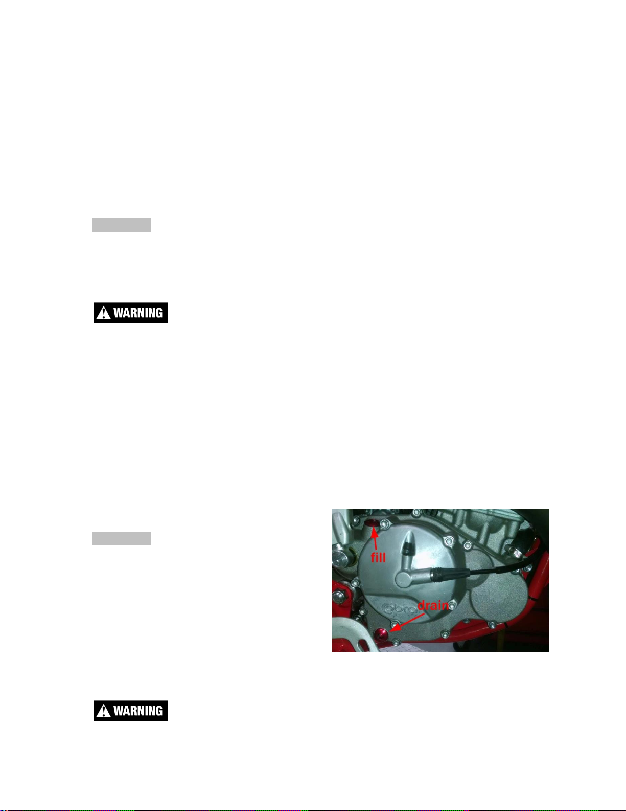
2. Lean the bike against something or set on stand with oil drain hole.
3. Using a 8mm Allen wrench, remove the oil drain bolt located on the right side
of the engine, on the clutch cover, near the brake lever (See Figure 1).
NOTE: You may need to adjust the brake pedal (up or down) to gain access to
the drain bolt.
4. After it has drained, reinstall the bolt being sure that the rubber gasket is in
place. Torque to 11 Nm (8 ft-lb).
5. Remove oil fill plug with an 8mm Allen wrench.
6. Carefully pour 16 oz (470 ml) of transmission oil into the oil fill opening.
7. Reinstall the oil fill plug making sure the rubber gasket is in place.
NOTE: Filling after an engine rebuild required additional transmission fluid. If the
engine is completely flushed of oil, refill with 18 oz (530ml).
Always capture and dispose of used oil properly (all auto parts stores accept
used oil). Dumping oil on the ground is illegal, inconsiderate, and can get you
disqualified from a race weekend quicker than cutting the track.
Chain adjustment
Tools required for chain adjustment
• 22 mm wrench or socket
• 2 - 11 mm open-end wrenches
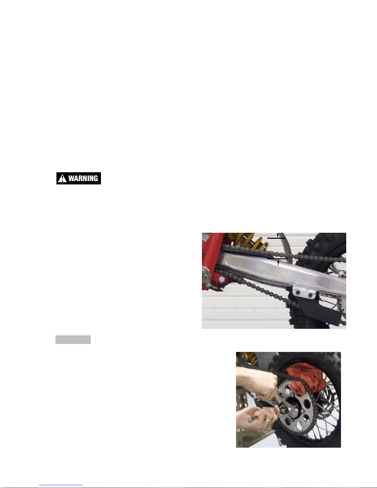
1. Make sure that the rear wheel is
aligned properly.
2. For proper adjustment, the chain
should have 35 mm free movement
just behind the chain block with no load
on the bike (Figure 2)
CAUTION:
Sit on the bike and verify that the chain has a
minimum of 12mm (1/2”) free movement when the
chain is at its tightest point.
3. If the chain requires adjusting, loosen the axle
with a 22mm wrench, and loosen the jam nut with
an 11mm wrench. Tighten the chain by rotating
the adjustor bolts clockwise (CW) or loosen the
chain by rotating the adjustor bolts (CCW).
Figure 2
Figure 3
11
4. Put a rag between the sprocket and chain, and roll the wheel backward to pull
the chain adjustor blocks tightly against the adjustor bolts (Figure 3).
5. Retighten the axle bolt to 25 ft-lb (34 Nm).
6. Retighten the adjustor jam nuts.
CAUTION:
Always check rear brake adjustment and free-play after adjusting the chain.
Lever Adjustment
Tools required for chain adjustment
• 4mm Hex Wrench
• 8mm Open End Wrench
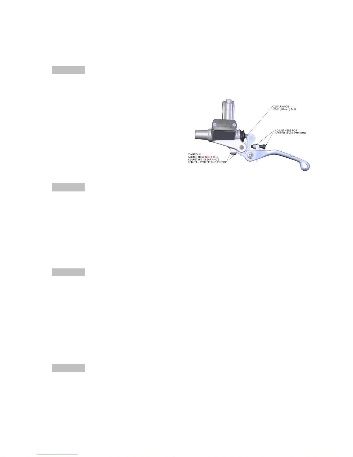
For lever position adjustment use a 4mm
hex wrench and an 8mm open end
wrench to adjust the socket head cap
screw between the lever and the bars.
CAUTION:
The small set screw in the master cylinder housing controls freeplay/clearance
between the piston and the roller. Improper adjustment of this screw will promote
brake or clutch failure. This scew is preset at the factory. If it requires asjustment
over time (as the screw tip makes an indentation in the aluminum) set it so that
there is a minimal .001" (.001mm) clearance between the roller and the head of
the piston (see figure).
Rear Brake Maintenance
CAUTION:
Too little brake pedal free-play will allow the brake pads to drag causing the pads
to wear prematurely and possible engine component failures. Too much free-play
will not allow the rider to apply the brakes quickly.
1. Set pedal height/position first, then
2. Set pedal free play.
Brake pedal height can be adjusted with the bolt and eccentric located under the
rear of the brake pedal. The free-play is adjusted with the adjustable plunger on
the end of the brake pedal.
CAUTION:
Use only DOT 4 compatible brake fluid
Setting rear brake pedal position:
1. Loosen the Cap Screw in the Eccentric (5mm Allen wrench).
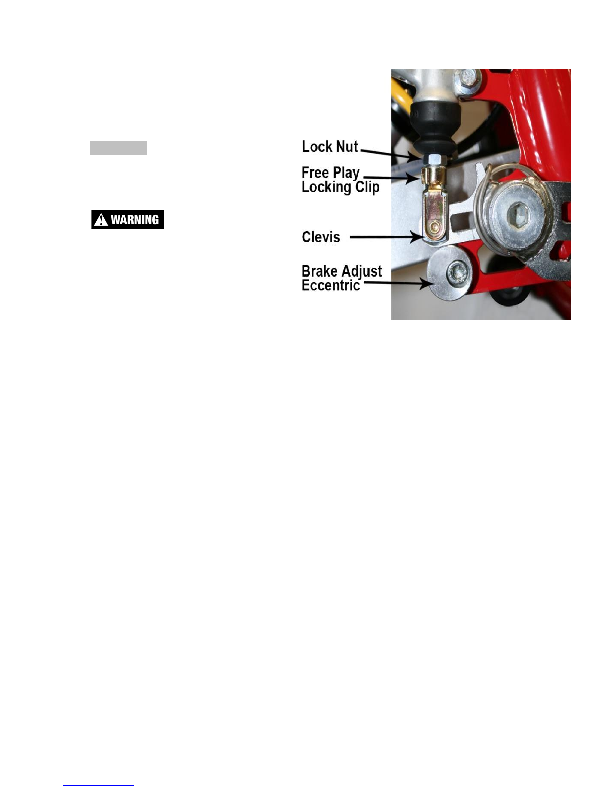
12
2. Rotate the eccentric so that the lever is comfortably reachable in both:
a. Standing riding
position, and
b. Sitting riding position.
3. Tighten Cap Screw (5 mm
Allen wrench).
CAUTION:
Adequate pedal free play is
required so that the brake pads do
not drag on the rotor.
Make sure that the free play locking
clip is installed such that one must
push forward, toward the front of
the bike, to remove. Otherwise the
clip is apt to come undone while
riding.
To adjust freeplay (see figure 2b):
1. Loosen the lock nut (10mm).
2. Undo the free play locking clip from around the brake adjustor (plunger),
with your hand by pushing it forward.
3. Slide the pin of the locking free play locking clip from the brake lever
4. Adjust as needed by rotating the clevis on the end of the adjustor
(plunger).
NOTE: Turning the clevis Clockwise will lengthen the adjustor (plunger),
removing free play from the system, and turning the clevis Counter-Clockwise will
shorten the adjustor (plunger) adding free play to the system.
Brake Bleeding Procedure
Tools Required:
• Front: Philips Screwdriver, 8mm wrench, Cobra bleed kit (BCKG0031)
• Rear: 3mm hex key (Allen wrench, T10 Torx bit/driver, Cobra bleed
kit(BCKG0031)
Procedure:
• Remove the brake fluid reservoir cover.
• Fill the syringe half full with brake fluid.
• Remove the brake caliper bleed screw.
• Attach the syringe to the brake caliper bleed access. Keep the syringe
oriented as not to allow air from the syringe into the system.
Figure 2b

13
• Using the syringe pull fluid through the system. Use caution not to let the
fluid in the reservoir to become low and introduce air into the system.
• Using the syringe push fluid back into the system until the reservoir is full.
• Repeat these actions of pulling and pushing fluid through the system a few
times.
• With the reservoir full, engage the brake lever/pedal and hold it there as if
engaging the brakes.
• While doing this pull on the plunger of the syringe. Doing this will cause a
vacuum in the system. The vacuum will swell the air bubbles which assist
in them moving throughout the system.
• Continue pulling a vacuum and release the brake lever/pedal (careful not
to allow the reservoir to become empty).
• Once again engage the brakes while continuing to pull a vacuum.
• When the reservoir is almost empty stop and push fluid back into the
system.
• Repeat these steps with the vacuum until no more air bubbles can be
removed from the system.
• Remove the syringe. Be sure to keep the caliper below the level of the
reservoir to allow the fluid to run out of the caliper and not allowing air into
the system.
• Reinstall the bleed screw, being sure that the ring is in place.
• Hold the brake pedal down (applying pressure) and momentarily crack the
banjo bolt atop the master cylinder. Repeat 3 times being careful not to let
the reservoir low on fluid
• Fill the reservoir with fluid (the fluid should be full enough that the fluid
spills out when placing the lid on) and replace the cover
Air Filter Cleaning
Tools recommended for air filter maintenance:
• 5 mm hex key (Allen)
• Foam filter oil
1. Removed seat with the 5mm hex key.
2. Unhook the air filter wire from its perch
3. Carefully remove the air filter and frame out the top
of the airbox making sure not to dislodge any dirt
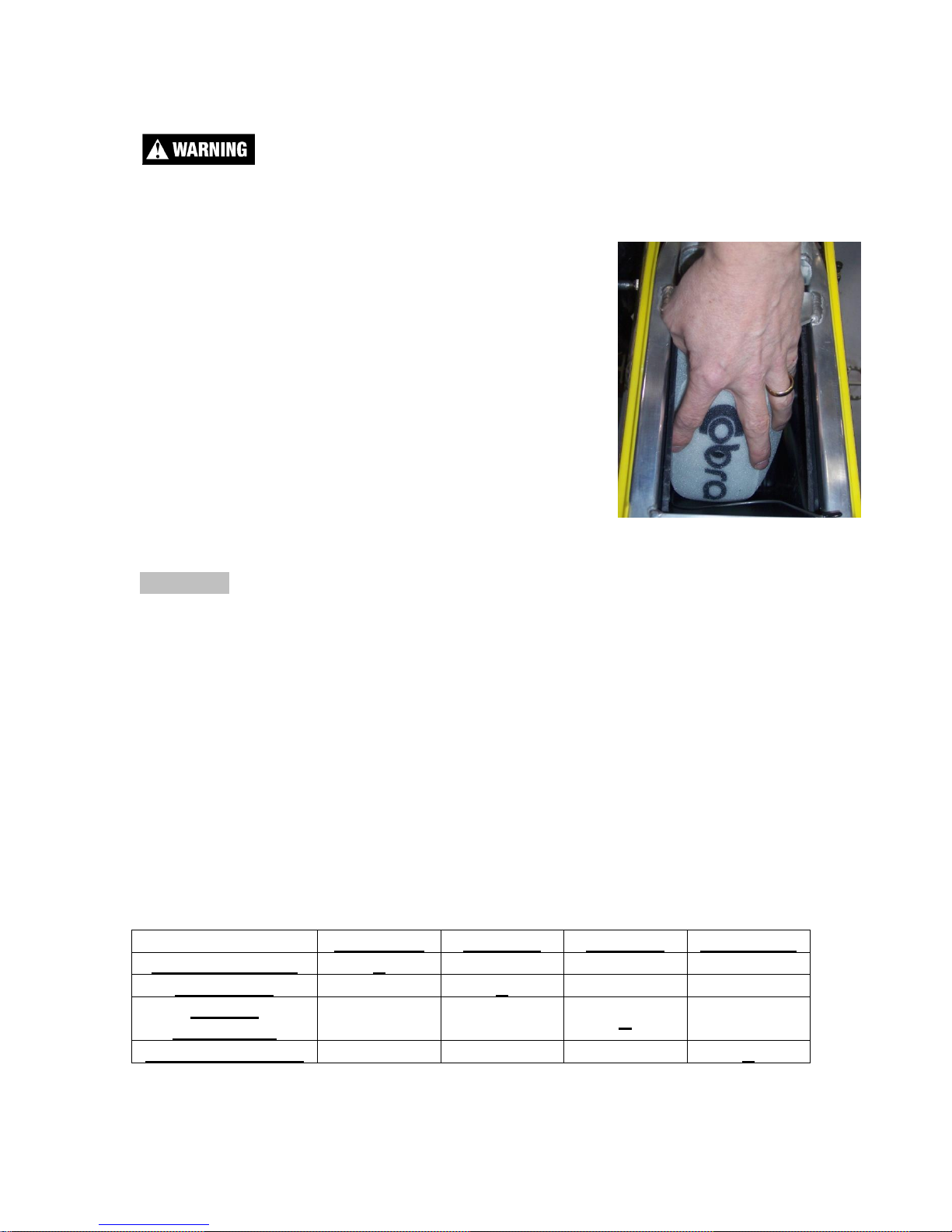
14
into the intake tract.
4. Clean the filter in a nonflammable solvent to remove the filter oil.
Do not clean the air filter with gasoline or other highly volatile petroleum product.
Diesel fuel, mineral spirits, or kerosene would be preferred but caution should still
be taken.
5. Clean the filter in hot soapy water to remove all dirt
particles.
6. Allow it to dry thoroughly.
7. Saturate with filter oil and remove excess.
NOTE: It is very important to keep the air filter clean
and properly oiled with high quality water-resistant foam
filter oil. Apply oil consistently because varied amounts
of oil will affect carburetor jetting.
8. Reinstall the filter assembly by pushing it down and
forward into the airbox making sure the lip of the
filter cage is properly seated into its receptacle
(figure 5). Reinstall the air filter cap and holding wire.
CAUTION:
Double check to insure that the filter is pushed in tight at the bottom
NOTE: Make sure you change or clean your filter after each moto. We
recommend carrying multiple filters in your toolbox, one for each practice session
and moto.
Fork Maintenance
Cobra strongly recommends that a professional service technician conduct all
internal maintenance other than changing springs and oil. This will help to ensure
safe and consistent operation.
For routine maintenance, the chart below provides suggested service intervals
for common procedures:
Each Ride
10 hours
20 hours
As Needed
Bleed excess air
X Change Oil
X
Change
Seal/Swiper
X
Change Bushings
X
Figure 5
15
Fork Air Bleeding
Tools required
• 3mm hex key (Allen wrench)
During normal operation, both fork legs will build up air pressure. This pressure
acts as an additional spring so it must be bled on a regular basis to maintain
consistent suspension operation. Before each ride, loosen the socket head cap
screw located at the front of each fork cap far enough so that any excess
pressure in the leg is relieved. After excess air is bled off, retighten the screw to 5
in-lb. Be careful not to lose or damage the sealing ring that is located under the
head of each bleed screw.
Fork Oil Replacement
Tools required
• 37mm Fork Cap Tool (MCMUTL37)
• 22mm closed-end wrench or socket
• 14mm open-end wrench
• Drift punch (12mm OD x 300mm long (1/2” x 12”))
• 5 & 6 mm hex key (Allen wrench)
• Mallet
• 2.5 wt. Bel-Ray fork oil
Disassembly procedure
1. Remove the front wheel.
a. Loosen the brake-side axle pinch bolts (5mm hex key)
b. Carefully remove the brake side axle cap using a closed-end wrench to
protect the cap from damage. (22mm wrench)
c. Loosen the non-brake side axle pinch bolts (5mm hex key)
d. Using the drift punch (a long 3/8 socket extension will also work),
remove the axle from the fork lugs by placing the punch inside the
hollow axle and tapping lightly on the exposed end with the mallet.
e. Carefully slide with wheel downward out of the brake caliper.
2. Remove the brake caliper from the fork leg (6mm hex key).
3. Loosen the fork caps (Cobra 37mm Fork Cap Tool).
4. Remove the fork legs from the triple clamps (5mm hex key).
5. One leg at a time:
a. Remove the fork cap from the fork tube.
b. Lower the fork tube to expose the fork spring.
c. Pull the fork spring down from the fork cap to expose the damper rod
lock nut. Secure this nut using a 14mm wrench.

16
d. With the 14mm wrench on the damper rod nut, use the 37mm fork cap
wrench to free the fork cap from the damper rod.
e. Remove the 14mm wrench and allow the damper rod to fall into the
cartridge tube.
f. Remove the fork spring.
g. Invert the fork to allow the oil to drain. Pump the damper rod assembly
several times to help any excess oil trapped in the cartridge to drain.
Assembly procedure
Completely collapse the outer fork tube onto the stanchion tube. Add enough 2.5
wt. Bel-Ray fork oil to fill the cartridge tube. Pump the damper rod up and down
slowly to help the assembly fill with oil.
1. Once the cartridge assembly is bled, continue to fill the fork with oil until it is
120mm +/- 2.5mm from the top of the fork.
2. Install the fork spring.
3. Use a flexible retrieving tool to pull the damper rod up through the fork spring
and thread the damper rod into the fork cap.
CAUTION:
Ensure that the fork cap is completely threaded onto the damper rod before it
makes contact with the lock nut.
4. Pull the fork spring down from the cap and torque the damper rod lock nut to
15 N-m (11ft-lb) with a 14mm wrench.
CAUTION:
The damper rod is hollow and will break if the nut is over tightened.
5. Ensure that the fork cap o-ring is in good condition, Use the 37mm fork cap
wrench to secure the fork cap to the fork outer tube. Torque the fork cap to 20
Nm (15 ft-lb).
6. Pump the fork leg several times to verify that it operates smoothly.
7. Install each leg back into the triple clamp. Torque each pinch bolt to 11N-m (8
ft-lb) making sure both legs are set to the same height in the clamps.
8. Reinstall the brake caliper.
9. Reinstall the front wheel.
1. Install axle through non-brake side fork lug and wheel hub
2. Slide wheel spacer over axle taking care to ensure that the internal
o-ring is in place.
3. Continue sliding axle through brake-side lug and reinstall axle cap
(6 ft-lb, 8 Nm)
4. Lightly torque all four axle pinch bolts
5. Drop the bike onto the ground, engage the front brake, and push up
and down on the handlebars several times to ensure that the front
forks and the front wheel are properly aligned with each other.
6. Apply final torque to all four axle pinch bolts (7.4 ft-lb, 10 Nm)
17
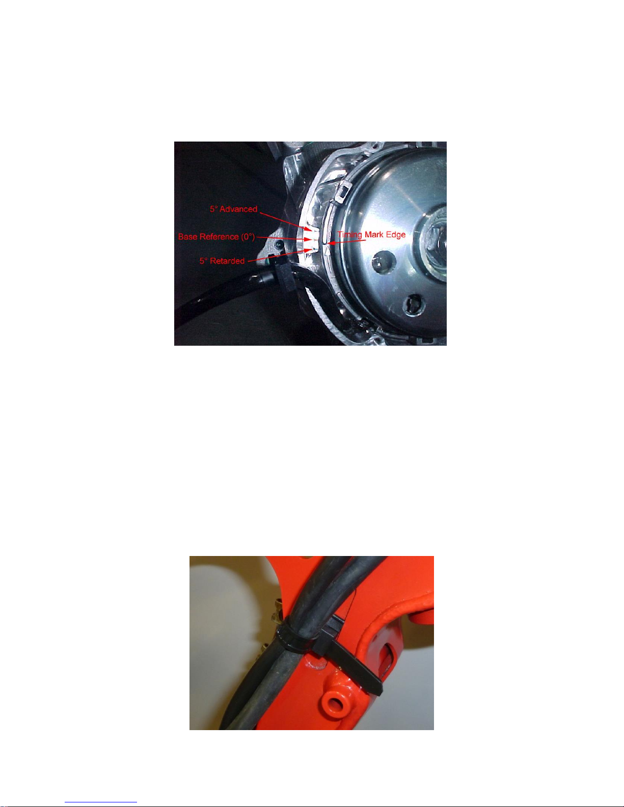
Ignition Timing
The ignition timing value for the CX65 is 0° retarded from the standard base
reference (0°). This can be verified by removing the ignition cover and looking as
shown in the figure below.
The center mark on the cases is the standard base reference timing mark (0°),
and the other two large marks are 5° advanced and retarded. The small timing
marks between 0 & 5° is 2.5°.
To change the timing, one must remove the flywheel with Cobra 65 flywheel
puller # MCMUTL05. After the flywheel has been removed, the timing can be
adjusted by loosening the stator bolts and rotating the stator to the desired
position.
Cable Ties
There is one location where we have used reusable frame mount cable ties this
year on the CX65.
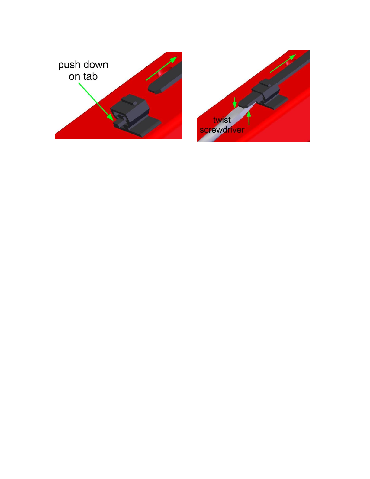
18
To disconnect these cable ties, use a screw driver as shown and push down on
the short tab. The tab will be hidden from view by the cable tie strap.
19
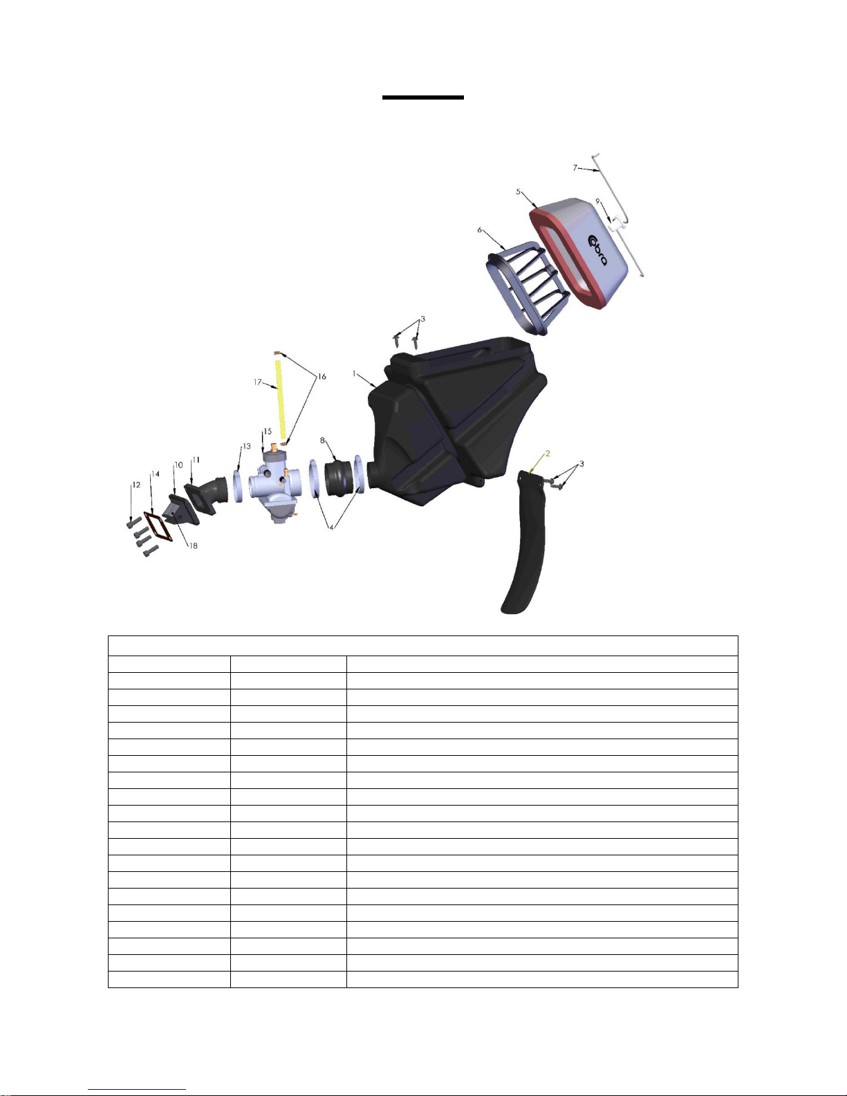
Parts
Parts – Air Box & Inlet System
Air Box & Inlet
REF #
PART #
DESCRIPTION
1
RCC60007
AIRBOX
2
TCC60008
MUD FLAP
3
HCSP0004
SCREW – PLASCREW
4
MCKGHO03
CLAMP, AIR BOOT TO AIR BOX
5
RCC60002
AIR FILTER
6
RCC60003
AIR FILTER CAGE
7
RCC60004
AIR FILTER WIRE
8
RCC60014
AIR BOOT, CARB TO AIRBOX
9
RCC60006
AIR FILTER CAP
10
ECC60006
REED ASSEMBLY
11
ECC60007
INLET MANIFOLD
12
HCBC0625
M6x25mm SOCKET HEAD CAP SCREW
HCWF0601
M6 FLAT WASHER
13
MCC60003
CLAMP, MANIFOLD TO CARB
14
ZCC60021
GASKET REED
15
RCR60026
CARBURETOR 26mm MIKUNI
16
MCMUCL04
HOSE CLAMP 8mm
17
FCMU0026
FUEL LINE
18
ECC60014
REED PETALS – REPLACEMENT
 Loading...