

Cobra Moto 2008 X50JR Service Manual

For parts orders contact your local dealer
To locate your closest Cobra dealer
log on to
www.cobramotorcycle.com
or call
(517) 437-9100
If you need technical assistance
contact your local dealer or call
the Cobra Technical Support Hotline at
(517) 437-9100
Cobra Motorcycle MFG., Inc.
240 Uran Street
Hillsdale, Michigan 49242
DISCLAIMER OF WARRANTY
This motorcycle is sold “as is” with all faults, obvious or not. There are no warranties
expressed or implied, including any warranty of merchantability and warranty of fitness
for any particular purpose.
“WARNING”
THE COBRA CX50JR IS A COMPETITION MODEL ONLY AND IS NOT
MANUFACTURED FOR, NOR SHOULD IT BE USED ON PUBLIC STREETS, ROADS
OR HIGHWAYS.
THE USE OF THIS BIKE SHOULD BE LIMITED TO PARTICIPATION IN
SANCTIONED COMPETITION EVENTS UPON A CLOSED COURSE BY A
SUFFICIENTLY SKILLED RIDER AND SHOULD NOT BE USED FOR GENERAL
OFF-ROAD RECREATIONAL RIDING.
IMPROPER USE OF THIS MOTORCYCLE CAN CAUSE INJURY OR DEATH.
THIS BIKE IS INTENDED FOR EXPERIENCED RACERS ONLY AND NOT FOR
BEGINNERS.
IT IS YOUR RESPONSIBILITY AS THE OWNER OF THIS COBRA MOTORCYCLE
OR AS THE PARENT, OR LEGAL GUARDIAN OF THE OPERATOR, TO KEEP THIS
COBRA MOTORCYCLE IN PROPER OPERATING CONDITION.
THIS BIKE WAS DESIGNED FOR RIDERS THAT WEIGH LESS THAN 80 LBS WITH
FULL RIDING GEAR AND SHOULD NOT BE OPERATED BY RIDERS THAT WEIGH
MORE THAN THAT.
BE SURE THAT THE RIDER ALWAYS WEARS ADEQUATE SAFETY GEAR
EVERYTIME HE OR SHE RIDES THEIR COBRA MOTORCYCLE.
IMPORTANT SAFETY NOTICE
Failure to follow WARNING instructions could result in severe injury or death to
the machine operator, a bystander, or a person inspecting or repairing the
machine.
CAUTION:
A CAUTION indicates special precautions that must be taken to avoid damage to
the machine.
NOTE:
A NOTE provides key information to make procedures easier or clearer.
MCCJ2008.6

Table Of Contents
General Information..............................................................................................5
Specifications - General....................................................................................5
Specifications - Torque Values..........................................................................6
Optional Components........................................................................................7
Break-In Procedure...........................................................................................8
Starting Procedure ............................................................................................9
Maintenance .......................................................................................................10
Tips .................................................................................................................10
Schedule .........................................................................................................11
Replacing Transmission / Clutch Lubricant .....................................................12
Proper Chain adjustment.................................................................................14
Air Filter Cleaning............................................................................................14
Fork Oil Replacement......................................................................................16
Frictional Drive (CFD)......................................................................................17
Parts ...................................................................................................................18
Parts – Airbox and Inlet System...................................................................... 18
Parts – Bars and Controls ...............................................................................19
Parts - Carburetor............................................................................................20
Parts - Carburetor............................................................................................20
Parts – Coolant System...................................................................................21
Parts – Electrical System ................................................................................22
Parts – Engine – Bottom End and Transmission............................................23
Parts – Engine Clutch and Kicker................................................................24
Parts – Engine – Water Pump .....................................................................25
Parts – Engine – Top End............................................................................26
Parts – Exhaust System..................................................................................27
Parts – Forks & Triple Clamps.........................................................................28
Parts – Forks – Leg Assembly.....................................................................29
Parts – Frame – Mounting Hardware I ............................................................30
Parts – Frame – Mounting Hardware II........................................................31
Parts - Frame – Mounting Hardware III........................................................32
3

Parts – Front Brakes .......................................................................................33
Parts – Front Wheel ........................................................................................34
Parts – Plastic Bodywork & Seat.....................................................................35
Parts – Rear Brake..........................................................................................36
Parts – Rear Wheel.........................................................................................37
Parts – Shock..................................................................................................38
Parts – Swingarm Assembly............................................................................39
Service................................................................................................................40
Engine Service................................................................................................40
Base Gasket Selection ................................................................................41
Engine Removal ..........................................................................................43
Complete Engine Disassembly Procedure ..................................................44
Top End Disassembly Procedure ................................................................44
Splitting the Cases.......................................................................................45
Engine assembly .........................................................................................46
Clutch..............................................................................................................48
Ignition.............................................................................................................53
Cooling System...............................................................................................55
Fuel & Air System............................................................................................59
Exhaust ...........................................................................................................62
Wheels & Tires................................................................................................63
Tuning.................................................................................................................63
Suspension .....................................................................................................63
Rear shock...................................................................................................65
Front Forks ..................................................................................................65
Gearing ...........................................................................................................66
Carburetion .....................................................................................................68
Troubleshooting..................................................................................................70
Index...................................................................................................................72
4
General Information
Specifications - General
Items CX50 JR
Dimensions
Wheelbase 35.75” (908mm)
Wheel size 10” (254mm)
Seat height 23.9” (607 mm)
Engine
Type 2-stroke, single cylinder, reed valve
Cooling system Liquid-cooled
Coolant Liquid Performance Mini Coolant or Antifreeze
Displacement 49.8 cc
Bore and stroke 39 mm x 41.7 mm, “V” head
Ignition system Electronic, analogic advance
Spark plug Champion 8339-1, 8332-1 hotter, 8904-1 colder
Gap 0.023” – 0.025” (0.58 – 0.64 mm)
Ignition timing 0.040” (1.0 mm) Before Top Dead Center (BTDC)
Fuel type High octane pump gasoline
Oil type
Fuel / oil mix ratios Between 32:1 and 40:1 (after engine Break-In)
Carburetion 14 mm Dell’Orto
RACE FUELS ARE NOT RECOMMENDED
Cobra Venom 2-cycle Race Oil
Slow (Pilot) jet 55
Float Height 16mm + 0.5mm (0.63” + 0.020”)
Transmission
Speed / Clutch Single / Cobra 3 shoe
Final drive ratio 13/37T or 14/38 T
Chain 420
Transmission / clutch oil type
Main Jet 92
Cobra Venom 3 Shoe Clutch Milk
Quantity 235 – 350 ml (8 – 12oz)
5

Chassis
Front tire 2.50 – 10
Pressure 15 psi minimum
Rear tire 2.75 – 10
Pressure 15 psi min. (20 psi for hard pack or rocky conditions)
Front fork Marzocchi 32mm
Fork oil type SAE 20 weight
Fork oil amount 200 ml (6.8 oz) oil change, 220 ml (7.4 oz) rebuild
Collapsed fork oil height 70 mm (2.75”) spring in, no spacer
Specifications - Torque Values
Torque Value
Fastener
Cylinder head nuts
Crankcase bolts
Spark plug (SP) (SP) (SP) M14 x 1.25
Stator bolts 2.1 25 2.8 M5 X 0.8
Stator cover bolts 1.7 20 2.3 M4 X 0.75
Clutch cover bolts 5.8 70 7.9 M6 X 1.0
Clutch nut (max.) 40 480 54 10 x 1.25*
Clutch bolts 12 144 16 M6 x 1.0
CFD nut 55 664 75 ½” x 20 LHT
Engine mount bolts 22 265 30 M8 X 1.25
Swingarm Pivot 21 250 28 M14 X 2.0
ft-lb in-lb Nm
8.8 105 12
8.8 105 12
Size &
Remarks
M6 X 1.0
M6 x 1.0
Shock Bolt 35 420 47 M10 x 1.5**
Water Pump
Impeller
Intake manifold bolts 4.6 55 6.2 M6 X 1.0
Ignition rotor nut 40 480 54 M10 x 1.25*
3.6 44 5 M5 x 0.8*
6
Rear Sprocket Bolts 18 216 24 M7 X 1.0**
Axle nuts 25 300 34 M12 X 1.25
* Apply high strength thread locking agent when installing
**Apply medium strength thread locking agent when installing
(SP) To apply the proper torque to the spark plug when inserting, one must first
screw the spark plug in until the metal gasket ring causes resistance and then
turn another 1/8 to ¼ turn.
Optional Components
Call your dealer, or the factory, for details
• Carburetor jets
• Pre-filter for the airbox
• Sprockets
o Front
o Rear
• Suspension Springs
Weight of Rider (lb) Fork Spring Shock Spring
Less than 38 (light) KCMZ0012A
(12 lb/in, 2.10 N/mm))
38 – 45 (std) KCMZ0012
(14 lb/in, 2.45 N/mm))
46 to 55 (stiff) KCMZ0012B
(16 lb/in, 2.80 N/mm)
• Suspension valving
Damping Rate Fork Valving
Compression
(right)
Soft (fast) KCMZ0033A KCMZ0032A SCMUOH07
Standard KCMZ0033 KCMZ0032 SCMUOH08
Hard (slow) KCMZ0033B KCMZ0032B SCMUOH09
• Tires
• Tubes or ‘Tire Balls’
Fork Valving
Rebound
(left)
SCMUOH04
(275 lb/in) red
SCMUOH05
(285 lb/in) yellow
SCMU0H06
(295 lb/in) white
Shock Valving
(kit)
7

Break-In Procedure
Your Cobra CX50 JR is a close-tolerance high performance machine and breakin time is very important for maximum life and performance. The CX50 JR can be
ridden hard after the first ½ hour break-in time but it is recommended that no
adjustments are made to the carburetion or suspension until the full 8 hours of
bike break-in has elapsed. Also, after the engine, transmission, and drive train
have been broken-in for the full 8 hours, the bike will be faster!
Use a fuel / oil mixture of 32:1 for the full 8 hour break-in period. Be sure to use
high octane pump gas with Cobra’s specially formulated Cobra Venom 2-cycle
Race Oil. (Part # MCMUOL02)
CAUTION:
Failure to use proper fuel, oil, or fuel/oil mixture may result in premature engine
wear or damage to the machine.
Adhering to the following break-in schedule will result in long lasting high
performance machine.
• Start bike on stand
• First 5 minute period, operate the bike on the stand with a combination of idle
and high RPM operation. (avoid prolonged high RPM but spin the rear
wheel good at least once or twice per minute)
• Allow bike to cool
• Ride for 15 minutes maximum (avoid prolonged high RPM operation and
avoid abusing the clutch with throttle blipping.
• Cool and inspect bike for loose fasteners.
• Next ½ hour of operation, avoid prolonged operation at Wide Open Throttle.
• After 1 hour of operation
o Check for loose bolts and nuts on the bike and retighten as
necessary (proper toque values are listed under Specifications).
o Clean the carburetor bowl.
o Change the transmission / clutch lubricant.
• After 8 hours of operation
o Change the fork oil.
o Have a Certified Cobra Mechanic change the shock oil.
• Your bike is now ready for the highest level of competition!
NOTE:
During break-in the bike will likely lose some engine coolant through the radiator
overflow hose. Losing up to 4 oz (120 ml, ½ cup) is normal. Proper coolant level
will cover the top of the radiator cores. Removing the radiator cap and looking
inside is the only way to check the coolant level.
8

Never open the radiator cap of a machine that has a hot or warm engine or one
that has recently been ridden. Burning and scalding could occur.
CAUTION:
It is important that the radiator cap is installed correctly and completely otherwise
engine damage could occur.
Starting Procedure
Before starting the machine inspect the following:
• Check for proper tire pressure in both tires.
• Observe the chain tension and adjust if necessary.
• Observe the coolant level and fill if necessary.
Verify that the chain rollers and sliders do not have improper wear.
• Verify that the handlebars are tight.
• Check the throttle for smooth operation and that it ‘clacks’ shut properly.
• Check for loose bolts and nuts, and re-torque as necessary.
• Verify that the air filter is clean and properly saturated with oil.
• Insure that the fuel tank contains an adequate volume of fuel / oil mixture to
complete the distance required. (High octane pump gas with Cobra’s
specially formulated Cobra Venom 2-cycle Race Oil)
• Turn the fuel on by rotating the fuel petcock knob to the vertically downward
position (reserve position is horizontally forward)
CAUTION:
For best results from your Cobra Motorcycle use only the recommended fuels.
Testing has shown that most ‘race’ fuels actually degrade performance.
Always wear a helmet and other protective riding gear.
When your pre-ride inspection is complete the bike may be started. For a cold
engine follow this procedure.
1. Place the motorcycle on a stand of sufficient strength that positions the
motorcycle in a level upright position with the rear wheel off the ground.
2. Pull up the choke knob and turn it to lock it.
3. Kick start the engine.
4. Rev the engine in short spurts, turning the throttle no more than 1/4 open
until the engine will run without the choke.
5. Verify a functional engine shut-off switch by shutting off the engine.
6. Restart the engine and proceed with riding when the engine is sufficiently
warm (i.e. the side of the cylinder is warm to touch).
9

CAUTION:
Never rev an engine full throttle when it's cold or slightly warmed up. Also, for
best clutch performance, warm up the bike before taking off.
This is a high performance race motorcycle. Too much application of throttle will
likely land your little racer on his or her arse. Fenders can be replaced but
bruised egos and other body parts take longer.
CAUTION:
Cobra recommends that you tell your child to take it easy the first couple of
minutes in practice until the engine comes up to full operating temperature.
CAUTION:
Make sure your riders’ foot is not resting on the foot brake while they are riding
.
Maintenance
It is important that you adhere to this maintenance schedule so as to promote the
longevity of your Cobra Motorcycle.
Tips
1. Cobra lubricants:
a. Cobra Clutch Milk has been specifically formulated to meet the
stringent temperature, frictional, and load requirements unique to
the high engine speeds and centrifugal clutch of the Cobra 50cc
motorcycles.
b. Cobra Two Cycle Oil exceeds the JASO FD & ISO-L-EGD
specifications, which are the worlds most stringent requirements on
lubrication, detergency, and smoke. Use only a 2-cycle oil that
meets these specifications.
2. Filling your transmission with more than 8.0 oz (235 cc) of lubricant may
help to transfer heat from the clutch. Filling with more than 12 oz (295 cc)
will degrade performance.
3. The cylinder base gasket has been ‘fitted’ for your engine. The code
number stamped into the engine cases will guide you to what thickness
base gasket is required during a common top end service. See the service
section of this manual to correspond a code number with a base gasket part
number.
4. Evaluate the bikes jetting only after it has been warmed up to race
temperatures.
5. A properly maintained machine is safer, faster, and more fun to ride.
6. New chains will stretch on first use. Never install a new chain prior to a
race. Always ‘break’ them in during practice.
10

7. Your Cobra Motorcycle has a 10 digit VIN (Vehicle Identification Number).
The first two digits indicate the model and the seventh indicates the model
year (MY).
a. Example, CMxxxx7xxx is a 2007 MY CX50 JR.
Schedule
• Between each ride
o Check the air filter (clean and re-oil as necessary).
o Insure the smooth operation of the throttle cable (throttle soundly
‘clacks’ shut).
o Check for frayed strands of the throttle cable inside the throttle housing
and replace if necessary.
o Check for adequate tire pressures and adjust if necessary.
o Check all nuts and bolts for proper torque and re-torque if necessary.
o Spray all moving parts with WD40 or other light oil.
o Check drive chain for
Proper tension and adjust if necessary.
Adequate lubrication and lubricate if necessary.
o Insure that the ignition stator and rotor are clean and dry.
o Check the frame for cracks in the metal or cracks in the paint that
might indicate that the metal has been stressed beyond it’s safe limits.
Replace or get properly rewelded as necessary.
o Check the rims for signs of stress, like cracks around the rim, spokes
and hub.
• Every 2 hours of operation
o Replace the transmission oil.
• Every 10 hours of operation
o Replace the fork oil.
o Have the shock oil replaced by a Certified Cobra Mechanic.
CAUTION:
1. Because of the amount of heat generated by the clutch and engine during
extended periods of riding, it is advisable to remove the ignition cover
afterward to allow the ignition to cool off. The heat transfers through the
cases and can damage the stator as it cools off because of lack of airflow
around the stator.
2. If you ever need to weld anything on the bike, disconnect the spark plug
cap, unplug the ignition, disconnect the kill switch, scrape the paint bare
near the area to be welded and put the ground clamp as close to the area
to be welded as possible.
Be sure the fuel tank and carburetor have been removed and safely located
away from the welding process.
11

3. The frame is 4130 Chrome Moly and it is important to weld it with the proper
rod and heat settings set as light as possible. Cobra recommends replacing
the frame with a new one if the old one becomes damaged. Use ER70S6
filler if welding on the frame.
4. If your kick-starter lever does not return properly, first try loosening the six
kick/clutch cover screws ½ turn. Hold the kick lever ½ way down while
retightening the six screws starting for the center and working out.
5. Inspect CFD slip torque every 10 hours of riding or replace the friction
papers and the load spring (Bellville spring) every 20 hours.
6. Check proper clutch engagement before and after each ride. If the clutch is
engaging properly DO NOT feel the need to take the clutch apart to;
measure the spring stack, clean the stack, replace the springs, etc... Cobra
has worked real hard to make a clutch that is low maintenance and so only
take it apart if it NEEDS to be maintained.
Replacing Transmission / Clutch Lubricant
Tools needed:
• Minimum of 235 ml (8 oz) Cobra Venom 3 Shoe Clutch Milk (Part #
MCMUGF01).
NOTE:
Up to 350ml (12 oz) can be applied without hurting performance.
Procedure:
1. Begin this procedure with a bike that has been ridden more than 5 minutes
but less than 10 minutes. It is desired to have the engine warm enough so
that the oil is ‘runny’ but not so hot that there is risk of being burned by the
engine or the oil.
Hot oil and hot components on the motorcycle may cause burns.
2. Lean bike against something or set on stand with oil drain hole.
3. Remove the oil drain plug located on the right side of the engine, on the
clutch cover, near the brake lever (figure 1).
12
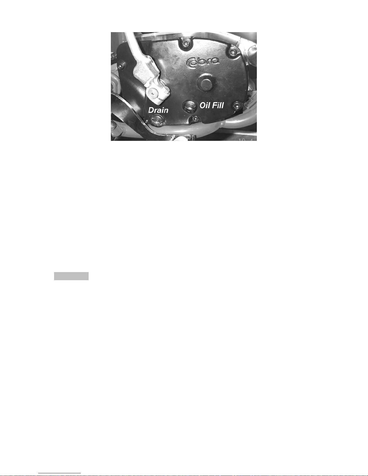
Figure 1
4. After it has drained, reinstall the plug, being sure that the gasket is in place.
5. Reapply oil from oil fill plug 235 cc (8.0 oz) Cobra Venom 3 Shoe Clutch Milk
thru the oil fill plug.
NOTE:
Putting additional oil, up to 350 ml (12 oz), can help clutch life. More than 350 ml
(12 oz) will degrade engine performance.
NOTE:
Lean bike over onto it’s left hand side so that the clutch cover is up unless you
have a squeeze bottle.
6. Reapply the oil fill plug, hand tight, being sure the gasket is in place.
CAUTION:
Cobra has spent considerable time and money developing the proper lubrication
to handle the harsh environment of the automatic clutch and transmission of this
motorcycle. Cobra’s specially developed Cobra Venom 3 Shoe Clutch Milk
(Part
# MCMUGF01) was formulated to provide superior lubrication and cooling
capability over extended periods of time and is the recommended lubricant for
your Cobra motorcycle.
13
Proper Chain adjustment
Tools required for chain adjustment
• 19 mm wrench or socket
• 13 mm wrench or socket
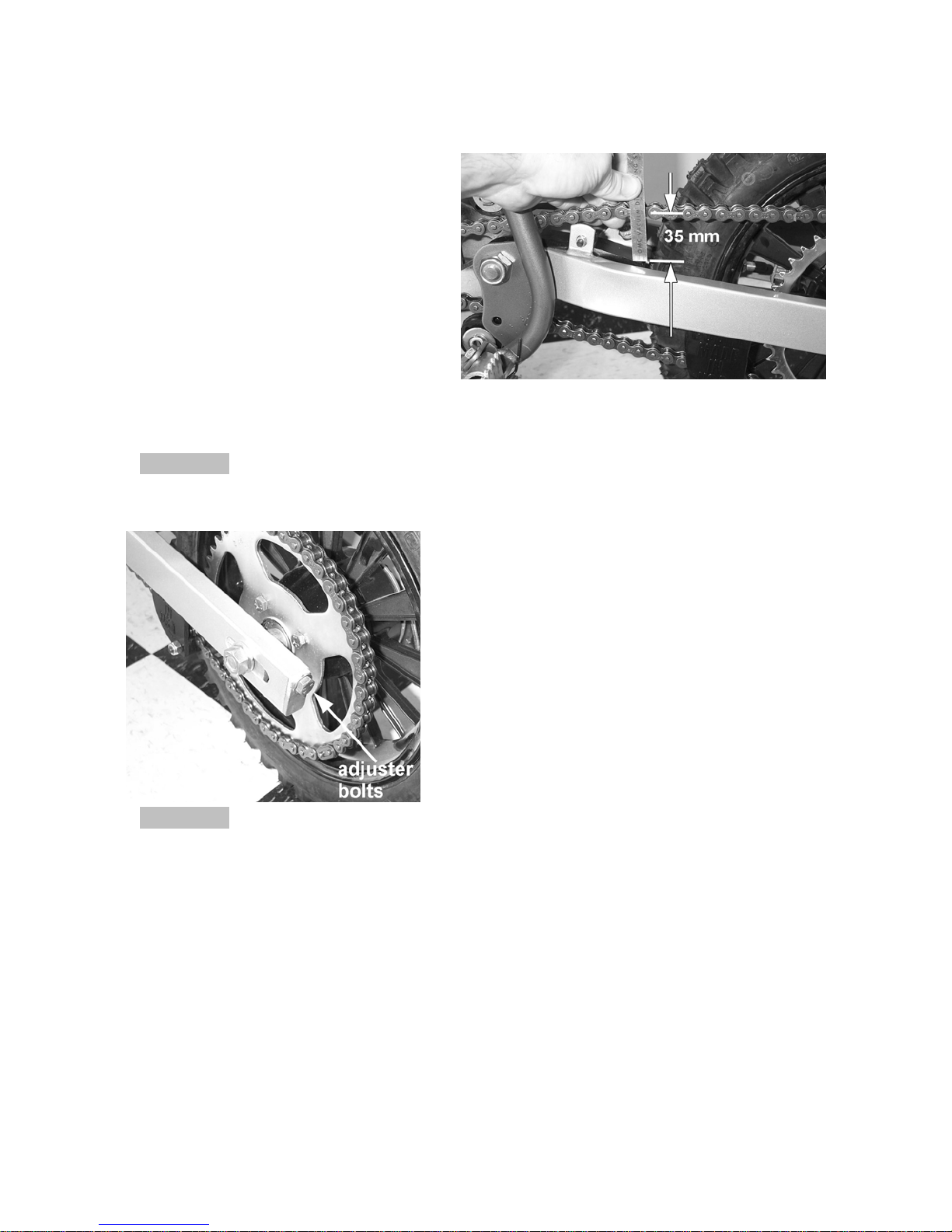
1. Make sure that the rear wheel is
aligned properly.
2. For proper adjustment, the chain
should have 35 mm (1 3/8”) free
movement just behind the chain
block with no load on the bike
(figure 2)
CAUTION:
Sit on the bike and verify that the chain has a minimum of 12mm (1/2”) free
movement when the chain is at it’s tightest point.
CAUTION:
Always check rear brake adjustment and free-play after adjusting the chain.
Figure 2
3. If the chain requires adjusting, loosen the
axle with a 19 mm wrench and tighten the
chain by rotating the adjustor bolts
clockwise (CW) or loosen the chain by
rotating the adjustor bolts (CCW).
4. Retighten the axel bolt to 25 ft-lb (34 Nm).
5. Retighten the adjustor bolt
Figure 3
Air Filter Cleaning
Tools recommended for air filter maintenance:
• #2 Phillips head screwdriver
• 4 mm hex key (Allen)
• Foam filter oil
Procedure
1. Removed the seat with the 4 mm hex key
2. Remove the filter/air inlet boot from the back of the carburetor with a phillips
14
screwdriver
3. Pull the filter / boot assembly back, up, and out the top of the airbox.
4. Clean the filter in a nonflammable solvent to remove the filter oil.
Do not clean the air filter with gasoline or other highly volatile petroleum product.
Diesel fuel or kerosene would be preferred but caution should still be taken. Hot
soapy water works well.
5. Clean the filter in hot soapy water to remove all dirt particles.
6. Allow it to dry thoroughly.
7. Saturate with filter oil and remove excess.
NOTE:
The Cobra is equipped with a special designed Air box. It is very important to
keep the air filter clean and properly oiled with high quality water-resistant foam
filter oil. It’s very important to oil your filter consistently each time because varied
amounts of oil will change your carburetor jetting.
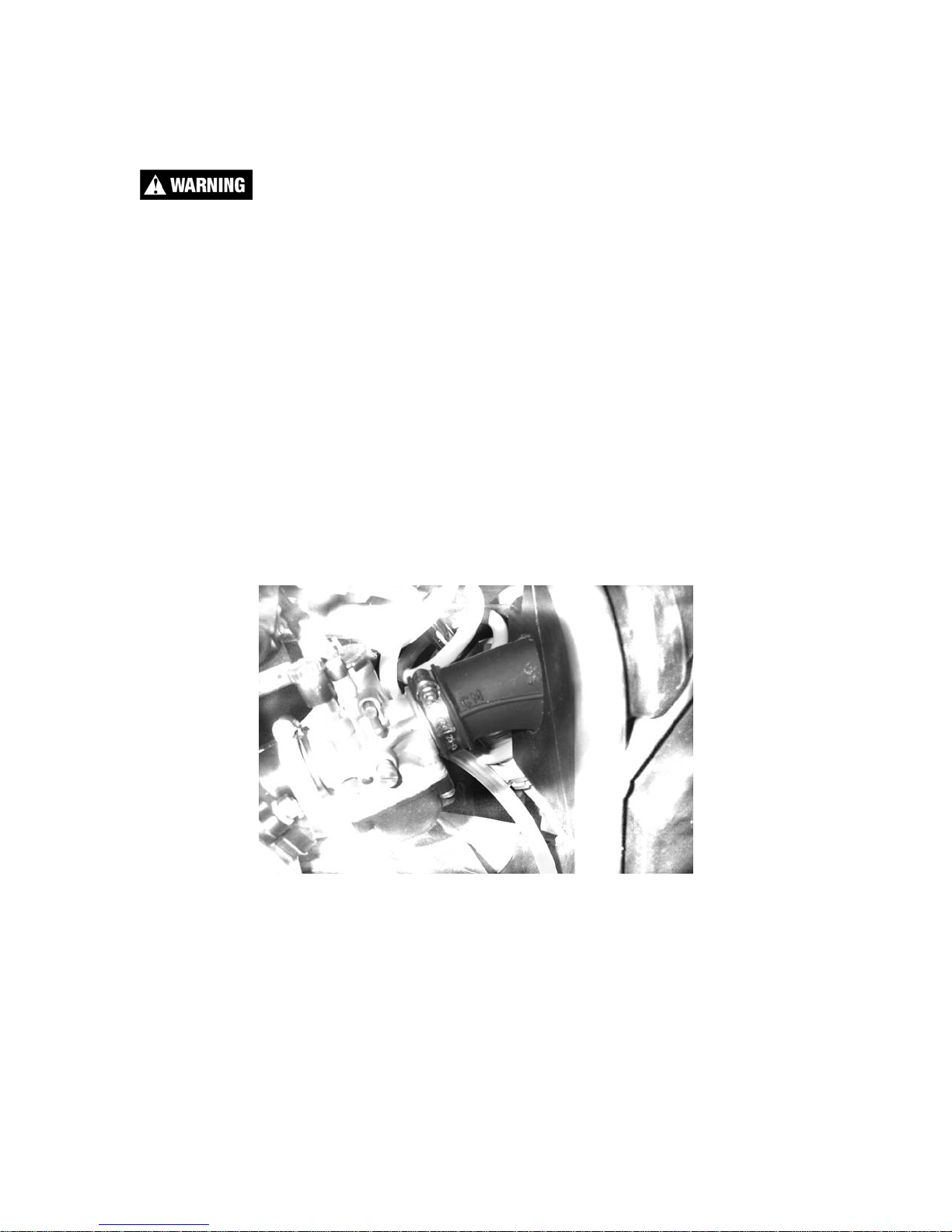
8. Reinstall the filter / boot assembly by pushing it down and forward into the
airbox making sure the letters “CM” are visible between the carburetor and
airbox (figure 8).
Figure 8
NOTE:
Make sure you change or clean your filter after each moto. We recommend
carrying multiple filters in your toolbox, one for each practice session and moto.
15

Fork Oil Replacement
Tools required
• 5 & 6 mm Allen wrench
• 19 mm wrench or socket (two required)
• Spring clip remover
Disassembly
1. Remove the front wheel.
2. Remove the fork legs from the triple clamps.
3. Perform the following on one leg at a time.
4. Using your hands, remove the black rubber plug from the top of the fork leg
exposing the white plastic cap.
5. Secure the fork leg assembly in a vice by gripping the leg across the flats
through which the axle bolt goes through.
6. Depress the white plastic cap inwards (down) and remove the wire spring clip
from its groove.
7. Remove the white cap, the fork spring preload sleeve, and the fork spring.
NOTE: Depressing the fork leg will facilitate removing the white cap.
8. The fork can now be turned upside down and drained.
Assembly
1. Fill the leg with 200 cc (6.8 oz) 20 wt fork oil.
2. Standard fork oil level is 70 mm (2.75”) from the top edge with the fork
collapsed.
NOTE: Remove the preload sleeve but leave the spring in for the measurement.
3. Install the preload sleeve.
4. Install and depress the white cap while installing the spring clip.
5. Fork may be reinstalled.
16
Frictional Drive (CFD)
The Cobra Frictional Drive (CFD) is essentially a slip clutch that dissipates torque
spikes transmitted from the rear wheel to the rest of the drive line and engine.
Instead of these torque spikes potentially damaging internal components, the
CFD allows the transmission to slip with respect to the engine. For this to occur,
the CFD must function properly by ‘slipping’ between a minimum torque value,
and a maximum torque value.
The slip torque of the CFD should be checked every 5 hours of operation.
Slip Torque
Minimum 55 75
Maximum 92 125
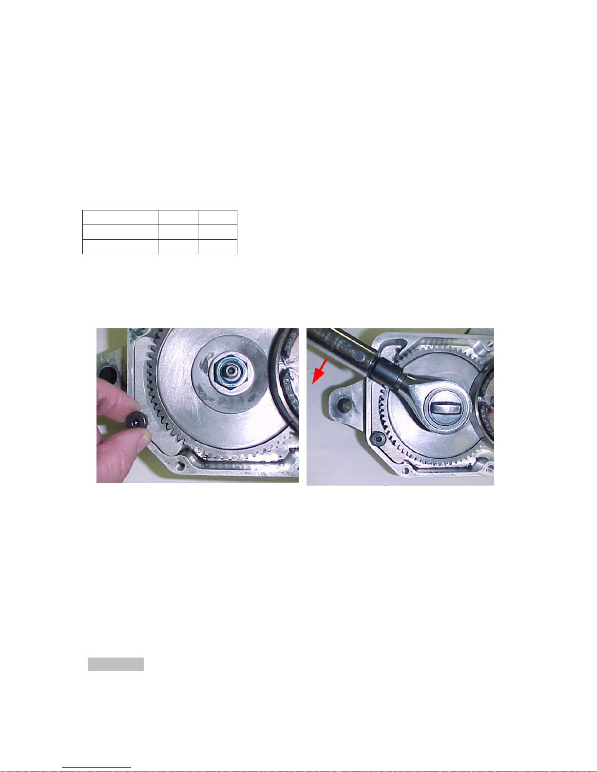
To properly measure the torque at which the CFD (Cobra Frictional Drive) slips,
one first access the slip clutch by draining the oil and removing the cover
exposing the CFD. Next, brace the CFD gear from turning with a suitable device
(Cobra tool EAMU0004 or similar).
Ft-lb N-m
Using a beam style torque wrench, turn the torque wrench counter clockwise and
observe the torque measurement when the shaft slips relative to the gear. Using
a preset value torque wrench, adjust the setting 55 ft-lb (75 Nm) and observe
whether the wrench clicks first or the shaft slips. If the shaft slips first, the slip
torque is below 55 ft-lb and the CFD needs servicing. If the wrench clicks first,
the CFD is of acceptable value.
NOTE
To loosen and tighten the blue CFD nut, use a strong wooden object (large
hammer handle) through the spokes of the rear wheel as a brace against the
swingarm to stop transmission shaft rotation.
CAUTION:
The blue CFD nut has left hand threads which require clock-wise rotation to
loosen.
17
Parts
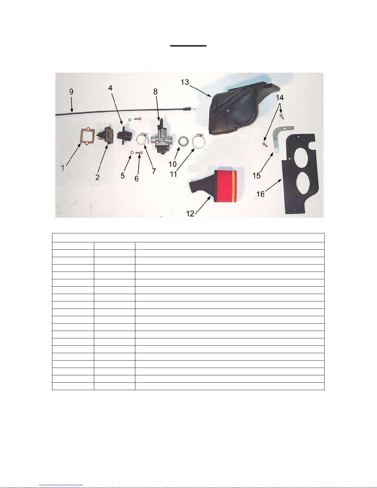
Parts – Airbox and Inlet System
Figure 7
Airbox and Inlet System
REF # PART # DESCRIPTION
1 ZCMU0132 GASKET – REED TO CYLINDER
2 ECKG0202 REED BLOCK ASSEMBLY
Not Shown ECKG0205 REEDS REPLACEMENT
4 ECKG0203 INLET MANIFOLD
5 HCWF0601 6MM FLAT WASHER
6 HCBC0625 M6X25 SOCKET HEAD CAP SCREW
7 MCKGHO04 HOSE CLAMP – CARBURETOR TO MANIFOLD
8 RACM0002 CARBURETOR 14MM
Not Shown FCMU0026 FUEL LINE 5”
Not Shown MCMUCL04 HOSE CLAMPS – FUEL LINE
Not Shown RCMU0022 VENT HOSE
9 FCMU0067 THROTTLE CABLE
10 RCCM1301 VELOCITY STACK
11 MCKGHO01 HOSE CLAMP – AIR BOOT TO CARBURETOR
12 RCMU0403 AIR FILTER WITH BOOT
13 RCMU0405 AIR BOX – CM
14 HCBB0612 M6X12 BUTTON HEAD BOLT (2 REQ’D)
15 RCMU1407 BRACKET – MUD FLAP
16 RCMU0406 MUD FLAP – CM
18
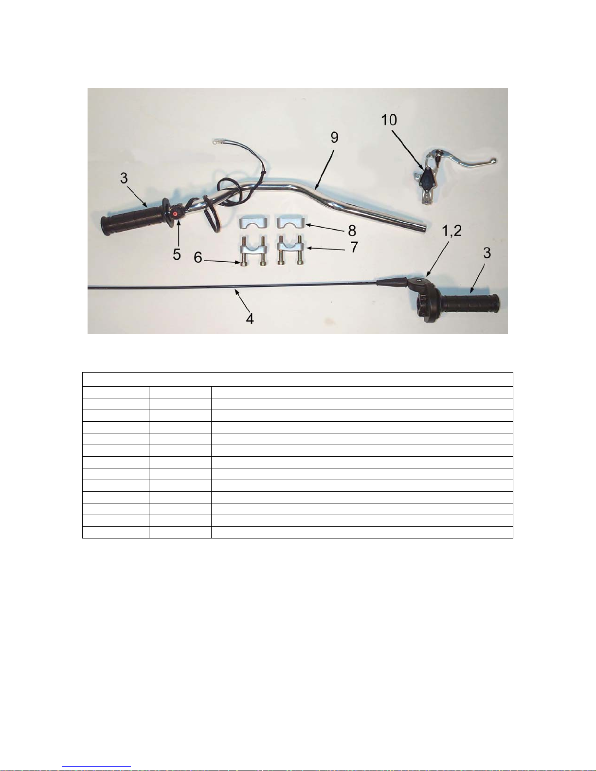
Parts – Bars and Controls
Figure 8
Bars and Controls
REF # PART # DESCRIPTION
1 FCMU0066 THROTTLE ASSEMBLY
2 FCMU0068 THROTTLE COVER
3 TCMU0008 GRIPS (SET OF TWO)
4 FCMU0019 THROTTLE CABLE
5 FCMU0033 KILL SWITCH ASSEMBLY
6 KCMZ0001 M8X50 SOCKET HEAD CAP SCREW (4 REQ’D)
7 KCMZ0003 LOWER HANDLE BAR CLAMP (2 REQ’D)
8 KCMZ0002 TOP HANDLE BAR CLAMP (2 REQ’D)
9 TCMU0019 HANDLEBAR - ALUMINUM
10 BCKG0024 BRAKE PERCH ASSY W/LEVER & BALL
FOR FRONT BRAKE ACCESSORIES SEE “FRONT BRAKE” SECTION
19
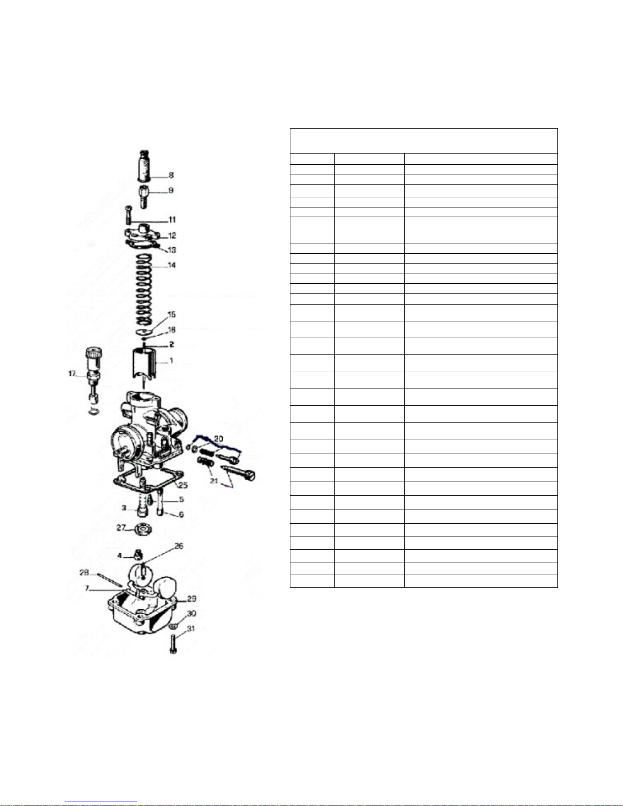
Parts - Carburetor
Figure 9
Carburetor
REF. # PART # DESCRIPTION
RCCM0001 COMPLETE CARBURETOR 14MM
1 RCMU0305 CARB SLIDE
2 RCMU0601 NEEDLE
3 RCMU00 ATOMIZER AU2.62
4 RCMU00xx MAIN JET, xx denotes size
5 RCMU00xx PILOT JET, xx denotes size
6 CHOKE JET
7 RCMU0301 FLOAT
8 RCMU0102 RUBBER CABLE CAP SEAL
9 RCMU0003 CABLE ADJUSTOR
11 RCMU0006 TOP CARB SCREW
12 RCMU0106 CARB TOP
13 ZCMU0007 TOP CARB GASKET
14 RCMU0004 SLIDE SPRING
15 RCMU0028 NEEDLE RETAINER PLATE
16 RCMU0007 NEEDLE CLIP
17 RCMU0204 CHOKE ASS’Y. 2001 CM
20 RCMU0009 FUEL MIXTURE SCREW
21 RCMU0011 IDLE ADJUSTMENT SCREW
25 RCMU0103 FLOAT BOWL GASKET
26 RCMU0107 FLOAT NEEDLE
27 RCMU0012 DIFFUSER
28 RCMU0016 FLOAT RETAINER PIN
29 RCMU0108 FLOAT BOWL
30 HCWF0401 WASHER 4MM FLAT
31 RCMU0201 BOTTOM FLOAT SCREW
Not Shown RCCM1301 VELOCITY STACK – 05 style
RCCM0314 14MM CARB RESTRICTOR
Not Shown FCMU0026 FUEL LINE 5”
Not Shown MCMUCL04 HOSE CLAMPS – FUEL LINE
Not Shown RCMU0022 CARB VENT HOSE 2” EACH
20
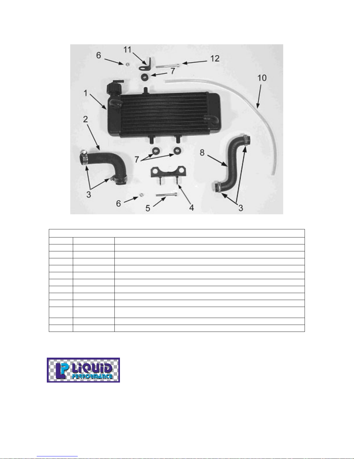
Parts – Coolant System
Figure 10
Coolant System
REF # PART # DESCRIPTION
1 ECMU0061 RADIATOR WITH CAP
2 MCMUHO02 RADIATOR HOSE LEFT
3 MCMUCL07 HOSE CLAMP
4 ECHA0003 MOUNTING BRACKET – RADIATOR BOTTOM
5 HCBC0607 M6X50 SOCKET HEAD CAP SCREW
6 HCNL0601 6MM LOCK NUT
7 MCKGGR00 GROMMET – RADIATOR MOUNTING
8 MCCMHO01 RADIATOR HOSE RIGHT
10 FCMU0049 OVERFLOW HOSE – 20”
Not
Shown
11 ECHA0109 MOUNTING BRACKET – RADIATOR TOP
12 HCBC0660 M6X60 SOCKET HEAD CAP SCREW
MCMUCL05 HOSE CLAMP, OVERFLOW HOSE
21
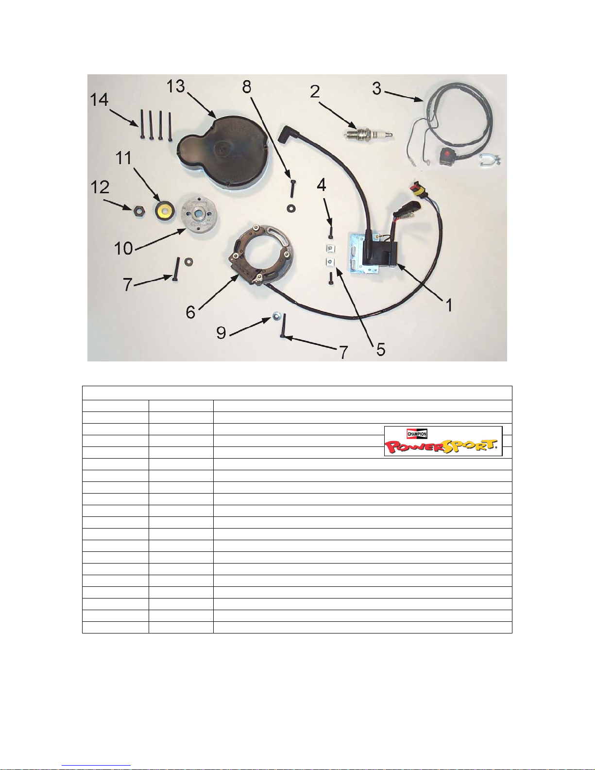
Parts – Electrical System
Figure 6
Electrical System
REF # PART # DESCRIPTION
1 IAMU0005 COIL W/SPARK PLUG CAP
2 ECMU0065 SPARK PLUG, CHAMPION (8339-1)
2H ECMU0067 OPTIONAL HOTTER PLUG (8332-1)
2C ECMU0066 OPTIONAL COLDER PLUG (8904-1)
3 FCMU0033 KILL SWITCH ASSEMBLY
4 HCBC0516 SCREW, M5 X 16 (2 PER)
5 HCCN0000 5MM CLIP NUT (2 PER)
6 ICMU0018 STATOR WITH GROMMET
7 HCBC0535 5mm x 35 SOCKET HEAD CAP SCREW (2 REQ’D)
8 HCBC0525 5mm x 25 SOCKET HEAD CAP SCREW
9 HCWF0504 WASHER FOR STATOR (3 PER)
10 ICMU0006 ROTOR
NOT SHOWN
11 ECKG0042 PULLEY, WATERPUMP CRANK
12 HCNS1001 NUT 10MM
13 ECKG0001 IGNITION COVER
14 HCBC0445 M4 X 45 SOCKET HEAD CAP SCREW (4 REQ’D)
NOT SHOWN
ICMU0012 WOODRUFF KEY
ZCKG0101 GASKET – IGNITION COVER
22
 Loading...