

Page 1

©2020 Cobra Electronics Corporation Version A
1 | Page
Page 2

Table of Contents
Table of Contents ................................................................................................................... 2
INTRODUCTION ...................................................................................................................... 3
HOW YOUR POWER INVERTER WORKS ................................................................................... 3
PRODUCT SERVICE AND SUPPORT .......................................................................................... 3
WHAT'S IN THE BOX ............................................................................................................... 3
OPTIONAL ACCESSORIES ......................................................................................................... 3
CONTROLS AND CONNECTIONS .............................................................................................. 4
IMPORTANT PRODUCT/SAFETY INFORMATION ...................................................................... 8
PENTAGON PROTECTION® ...................................................................................................... 9
GETTING STARTED ................................................................................................................. 10
POWER CONSUMPTION ........................................................................................................ 10
MOUNTING THE INVERTER .................................................................................................... 11
INSTALLATION REQUIREMENTS ............................................................................................. 12
CONNECTING TO A VEHICLE BATTERY .................................................................................... 12
PRO 1500W INSTALLATION INSTRUCTIONS ........................................................................... 13
PRO 2500W & 3000W INSTALLATION INSTRUCTIONS ............................................................ 16
TURNING YOUR INVERTER ON AND OFF ................................................................................ 19
CHANGING THE LOW VOLTAGE ALARM SETTING ................................................................... 20
COBRA REMOTE ON/OFF CONTROLLER WITH FAST CHARGE USB .......................................... 21
OPERATING INDICATORS ....................................................................................................... 22
OPERATING LIMITS ................................................................................................................ 23
TROUBLESHOOTING GUIDE ................................................................................................... 24
SPECIFICATIONS .................................................................................................................... 25
MAINTENANCE & PRODUCT SERVICE ..................................................................................... 25
REMOTE ON/OFF CONTROLLER with FAST CHARGE USB OPERATING INSTRUCTIONS……………26
WARRANTY & TRADEMARK ACKNOWLEDGEMENT ................................................................ 33
MOUNTING TEMPLATE .......................................................................................................... 34
2 | Page
Page 3

INTRODUCTION
Thank you for purchasing the Cobra PRO Series Power Inverter. Used properly, this Cobra
product will give you reliable power to run your appliances and devices. Please read this
manual thoroughly before you install and set up your new power inverter.
HOW YOUR POWER INVERTER WORKS
The Cobra PRO Power Inverter is a power conversion device that is designed and built to
operate from low Voltage DC (Direct Current) power from your vehicle battery and converts it
to standard 115 Volt AC (Alternating Current) power like you have in your home. This
conversion process allows you to use many of your household appliances and electronic
products in automobiles, RVs, boats, trucks and virtually anywhere else with a 12 Volt battery.
PRODUCT SERVICE AND SUPPORT
For any questions about operating or installing this new Cobra product, PLEASE CONTACT
COBRA FIRST…do not return this product to the retail store. The contact information for Cobra
will vary depending on the country in which you purchased and utilize the product. For the
latest contact information, please go to www.cobra.com/support or call 1-800-543-1608.
If your product should require factory service, please go to www.cobra.com/support and follow
the instructions.
WHAT’S IN THE BOX
• PRO Power Inverter (1500W, 2500W or 3000W)
• (2) 48-inch #4AWG Power Cables (PRO 1500W)
• (4) 48-inch #4AWG Power Cables (PRO 2500W)
• (4) 48-inch #2AWG Power Cables (PRO 3000W)
• Terminal Protector Boots
• Quick Start Guide
• Remote On/Off Controller with Fast Charge USB (PRO 3000W only)
OPTIONAL ACCESSORIES – available at www.cobra.com
• CPIALCDG1 - Remote On/Off controller with Fast Charge USB
3 | Page
Page 4
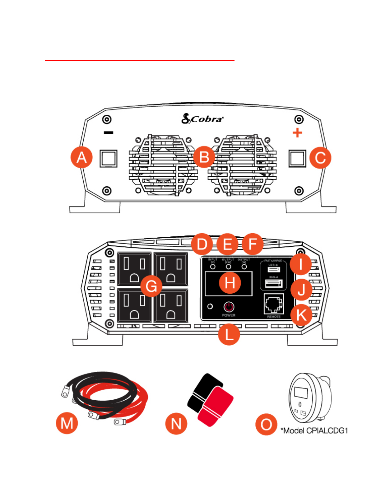
CONTROLS AND CONNECTIONS
PRO 1500W Features
4 | Page
Page 5

A. Negative Power Input Terminal
B. Cooling Fans – regulate the temperature of the inverter, turning on
when temperature exceeds the preset limit, and turning off when
the temperature reduces
C. Positive Power Input Terminal
D. Green LED – Battery Voltage Indicator (V)
E. Yellow LED – Output Power Indicator. When active, output power
in is kilowatts (kW)
F. Red LED – Output Power Indicator. When active, output power is
in Watts (W)
G. (4) GFCI Protected AC Outlets
H. Digital Display showing Battery Voltage (V), Power in kilowatts (kW),
Power in Watts (W) and Error Codes
I. USB-C Fast Charge port (5V/9V/15W)*
J. USB-A Fast Charge port (5V/9V/15W)*
K. Port for Cobra Remote On/Off Controller with Fast Charge USB
(Sold Separately)*
L Power Button
M. Power Cables
N. Inverter Terminal Protector Boots
O. Cobra Remote On/Off Controller with Fast Charge USB
(Sold Separately)
* = Fast Charge works only on devices capable of supporting a charge up to 10W
5 | Page
Page 6

PRO 2500W and 3000W Features
6 | Page
Page 7

A. Negative Power Input Terminal
B. Cooling Fans – regulate the temperature of the inverter, turning on when
temperature exceeds the preset limit, and turning off when the temperature
reduces
C. Positive Power Input Terminal
D. Green LED – Battery Voltage Indicator (V)
E. Yellow LED – Output Power Indicator. When active, output power in is
kilowatts (kW)
F. Red LED – Output Power Indicator. When active, output power is in Watts
(W)
G. (4) GFCI Protected AC Outlets
H. Digital Display showing Battery Voltage (V), Power in kilowatts (kW), Power
in Watts (W) and Error Codes
I. USB-C Fast Charge port (5V/9V/15W)**
J. USB-A Fast Charge port (5V/9V/15W)**
K. Port for Cobra Remote On/Off Controller with Fast Charge USB (Sold
Separately)*
L Power Button
M. Power Cables
N. Inverter Terminal Protector Boots
O. Cobra Remote On/Off Controller with Fast Charge USB
(Sold Separately)*
*Included with PRO 3000W/Sold Separately from PRO 2500W
** = Fast Charge works only on devices capable of supporting a charge up to 10W
7 | Page
Page 8

IMPORTANT PRODUCT /SAFETY INFORMATION
Before installing and using your Cobra power inverter, please read these general precautions and
warnings.
Caution and Warning Statements
Special attention must be paid to the CAUTION and WARNING statements in the manual.
CAUTION: Statements specify conditions which could cause damage to the unit or other equipment.
WARNING: Statements identify conditions that could result in personal injury or loss of life.
General Precautions
1. Never install the inverter in a boat’s engine compartment where gas and battery fumes are
present.
2. Do not operate the inverter if it has been dropped or damaged in any way.
3. Do not open the inverter; it contains no user-serviceable parts. Attempting to service unit could
cause electrical shock.
NOTE: Internal components remain charged after all power is disconnected.
3. Do not expose the inverter to rain, snow, bilge water or spray.
4. Do not obstruct the ventilation openings.
5. Do not install the inverter in zero-clearance compartment.
6. Do not allow water or liquids in contact with the power inverter
7. Do not use appliances with damaged or wet cords.
CAUTION: This inverter should be used in negative ground applications only.
CAUTION: The inverter must only be connected to batteries with a nominal output voltage of 12
volts. Do not connect the power inverter to a 6 Volt battery and will be damaged if connected to a
24 Volt battery.
WARNING: Power inverters contain components that tend to produce arcs or sparks. To prevent fire
or explosion, do not install the inverter in areas or compartments containing batteries or flammable
materials or in locations that require ignition-protected equipment.
WARNING: To avoid fire, do not cover or obstruct the ventilation openings. Do not install the power
inverter in a tight space or closed compartment where airflow may be restricted.
Proposition 65: Warning: Wash Hands After Handling Power Cord
The power cord on this product contains lead, a chemical known in the state of California to cause
birth defects or other reproductive harm.
8 | Page
Page 9

Caution: Rechargeable Appliances
Certain chargers for small nickel cadmium batteries can be damaged if
connected to a Cobra PRO Power Inverter. Two particular types of equipment
are prone to this problem:
1. Small battery-operated appliances such as flashlights, razors, and night lights
that can be plugged directly into an AC receptacle to recharge.
2. Certain battery chargers for battery packs used in hand power tools. These
chargers have a WARNING label stating that dangerous voltages are present at
the battery terminals.
This problem does not occur with the vast majority of battery operated equipment. Most use a
separate charger or transformer that is plugged into the AC receptacle and produces a low voltage
output. If the label on the AC adapter or charger states that it produces a low voltage AC or DC output
(less than 30 volts), the inverter will have no problem powering the adapter safely.
Cobra PRO Output Waveform
Some very sensitive electronic equipment may not operate satisfactory on the output waveform referred
to as "modified sine wave" which this inverter is designed. It is a stepped waveform designed to have
characteristics similar to the sine wave shape of utility power. A waveform of this nature is suitable for
most AC loads (including linear and switching power suppliers used in electronic equipment, transformers
and motors).
PENTAGON PROTECTION®
Cobra power inverters provide five levels of protection:
1. Over-Temperature: Auto-shut off will occur when the safe operating temperature has been
exceeded.
2. Reverse Polarity: The inverter will not operate if connected incorrectly to the power source.
3. Over-Voltage: Auto-shutdown will occur if the DC input exceeds safe operating levels.
4. Low Voltage Alarm: The inverter will sound an alarm to indicate a low battery voltage condition.
5. Low Voltage Cutoff: The inverter will automatically shut off to prevent a dead battery condition.
For detailed specifications go to Specifications section of this manual, starting on page 25.
9 | Page
Page 10
GETTING STARTED
This section provides you with the basic information about the inverter and a few tips before installation.
To get started, you will need:
1. A 12 Volt DC battery (i.e. vehicle battery). In order to understand how much current your battery
must deliver, divide the number of Watts from your AC appliance or device by 10.
2. Cables to connect your inverter to the vehicle battery. These come with your PRO Inverter and
provide a length of 48".
DETERMINING THE POWER REQUIREMENTS FOR YOUR PRO INVERTER
Before you turn on your power inverter and plug in an appliance or device, you will want to understand
its power requirements.
To determine the requirements, you will need to know the Watts of your device. This can be calculated by
multiplying the Amps by 110 Volts (See Below).
POWER CONSUMPTION
For each piece of equipment you will be operating from the power inverter, you must determine the
battery’s reserve capacity (how long the battery can deliver a specific amount of current – in
automotive batteries, usually 25 ampere) or ampere-hour capacity (a measure of how many amperes
a battery can deliver for a specified length of time).
Example – Ampere-hour capacity: a battery with an ampere-hour capacity of 100 ampere-hours can
deliver 5 ampere for 20 hours before it is completely discharged.
To determine the battery ampere-hour capacity you require:
1. Determine how many Watts each piece of equipment consumes. This can normally be found on the
product label. If only the Amperage is provided, then multiply the Amps by 115 to determine the
power in Watts.
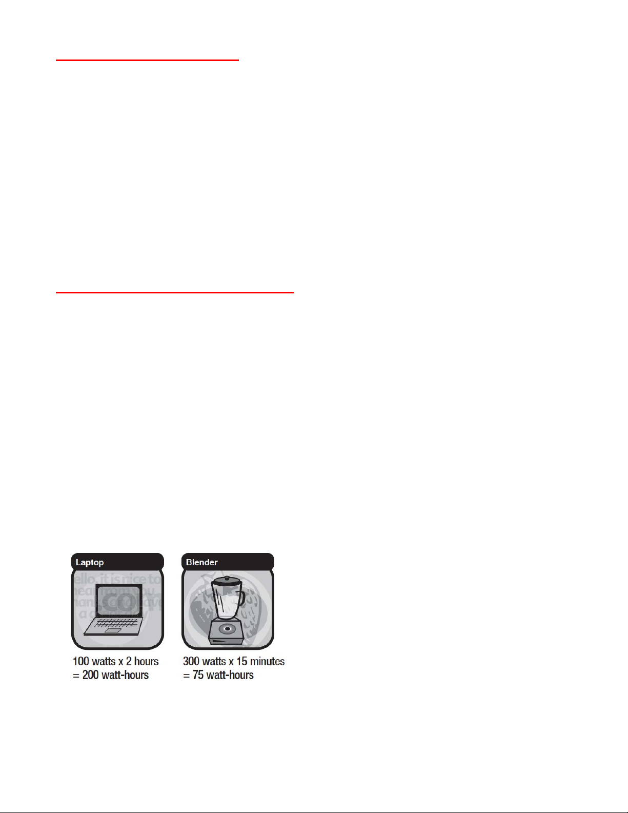
2. Estimate how long you need your appliance to run.
3. Now calculate the Amp-hour rating for the battery. You can do this by multiplying the total AC
load (in Watts) by the length of time (in Hours) needed to run your appliance. This will give you
the Watt-Hours needed.
4. Divide the watt-hours by 10 to determine how many battery (12 volt) ampere-hours will be
consumed.
10 | Page
Page 11
Multiply: AC AMPS X 110 (AC Voltage) = WATTS. This formula yields a close approximation of the
continuous load of your appliance.
Multiply: WATTS X 2 = Starting load for most appliances, tools and devices. This formula yields a close
approximation of the starting load for most appliances. Exceptions are motorized appliances such as
pumps, freezers, and air conditioners. These appliances can have startup loads of up to eight times the
rated Watts.
For electrically sensitive equipment, contact the manufacturer to determine if the device you are using is
compatible with modified sine wave AC. If not, then a Pure Sine Wave Inverter is recommended.
Determining the DC Power Requirements
Your inverter requires the input of a 12-Volt battery. To calculate the approximate power in Amps a 12Volt battery bank you need to know the current, or Amps required for powering the continuous AC load.
A shortcut method is to divide
of the PRO 3000W Power Inverter is 3000 Watts
VDC. Add to the
load any DC appliances that may be powered by the battery bank.
the continuous AC load Wattage by 10.
. The current (Amps) is: 3000/10 or 300 Amps at 12
For example, the continuous load
MOUNTING THE INVERTER
Do not mount the power inverter under the hood of any vehicle. Choose a cool, dry, and well-ventilated
area inside the vehicle as close to the battery as possible. Place the power inverter on a flat, secure
surface. Make sure there are no wires, fuel lines or fluid tanks directly behind the wall or surface being
drilled. When mounting, secure the power inverter in place using corrosion-resistant mounting hardware
(not included).
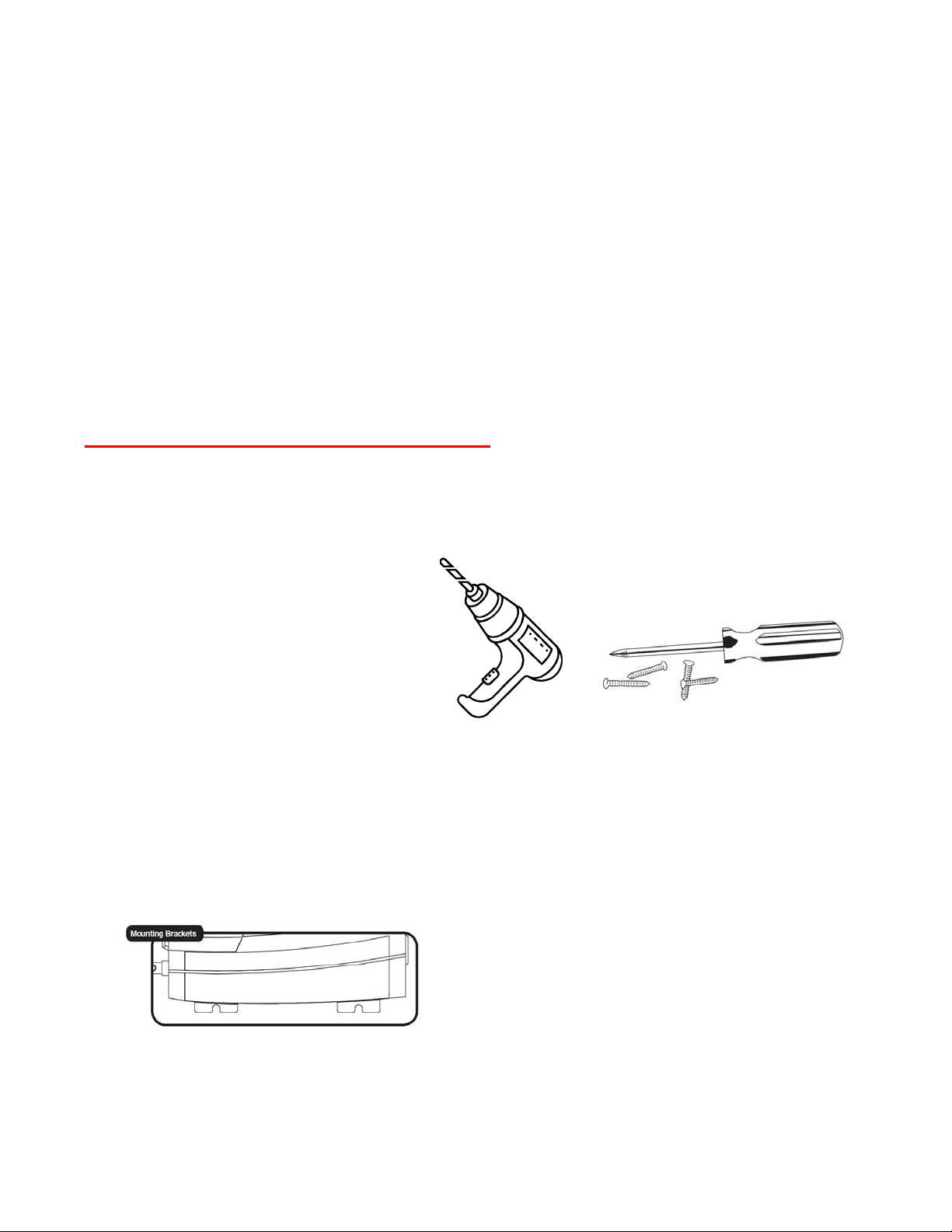
What you will need:
• Assess your mounting needs depending
on the inverter and type of surface you
are mounting (i.e. wood or fiber glass)
• Gather the necessary tools depending
on the surface (i.e. drill or screwdriver)
• Determine size of mounting hardware.
Use only corrosive resistant screws (not included)
Mounting Instructions:
1. Make sure the inverter is OFF.
2. Check for wires, fuel lines or fluid tanks behind the wall or surface you plan to drill.
3. Position the power inverter horizontally when choosing the mounting location. If mounted on a wall
be sure the front of the inverter is facing out. Do not mount vertically to prevent debris or dust from
falling into the power inverter.
4. Mark the locations of the mounting screws before drilling.
5. Remove the inverter and drill the (4) mounting holes.
6. Fasten the inverter to the mounting surface using corrosion-resistant screws (not included).
11 | Page
Page 12

INSTALLATION REQUIREMENTS
The inverter must be installed in an area that meets all of the following requirements:
1. Dry - Do not place in an area where water can drip or splash on the inverter.
2. Cool - Ambient air temperature should be between 30°F and 105°F (0°C and 40°C).
The cooler the better.
3. Ventilate - Allow at least one inch (three cm) of clearance around the inverter for proper airflow.
Make sure that ventilation openings on the ends of the unit are not obstructed.
4. Safe - Do not install the inverter in the same compartment as a battery or in any compartment that
contains flammable liquids such as gasoline.
5. Close to Battery - Install unit as close to battery as possible (without being in the same
compartment) to minimize the length of cable required to connect the inverter to the battery. It is
better and cheaper to run longer AC wires than longer DC wires (cables).
CAUTION: To avoid fire, do not cover or obstruct ventilation openings. Do not install inverter in a zero-
clearance compartment. Overheating may result.
CAUTION: The inverter must only be connected to batteries with a nominal output voltage of 12 volts. It
will not work with a 6 volt battery, and will be damaged if it is connected to a 16 volt battery.
WARNING: This unit contains components which can produce arcs or sparks. To prevent fire or explosion,
do not install in compartments containing a battery or flammable materials, or in a location
which requires ignition protected equipment.
WARNING: This unit is suitable for installation in negative ground applications only. Do not attempt to
install to a positive ground application.
CONNECTING TO A VEHICLE BATTERY
Power wire and wiring are very important to the performance of the inverter. Because the inverter has a
low voltage, high current input, low resistance wiring is essential between the battery and inverter. This is
so it can deliver the maximum amount of energy to the load.
For safety reasons, it is recommended to install a properly rated ANL fuse (not included) on the red cable
as close to the positive (red) battery terminal as possible. If you have a dual cable installation, install a
properly rated ANL fuse on each red cable. Cut about 12 inches from ring terminal and install fuse. Use (1)
150 Amp ANL fuse or equivalent for the PRO 1500W, (2) 150 Amp ANL fuses or equivalent for the PRO
2500W, or (2) ANL 200 Amp ANL fuses or equivalent for the PRO 3000W power inverter.
Do not use aluminum wire. Aluminum has about one-third more resistance than copper wire of the same
size, plus it is difficult to make good, low-resistance connections to aluminum wire. Your PRO Power
Inverter comes with heavy duty copper cladded cable for connections between the battery and inverter.
Keep the cable length as short as possible. The recommendation is no more than six feet. This will keep
the voltage drop to a minimum.
If the cable has too much voltage drop, the inverter may shut down when drawing higher currents
because voltage at the inverter may drop below 10 volts. If you must use longer cables, make sure you
choose a thicker or heavier gauge cable appropriate for your installation requirements.
12 | Page
Page 13

PRO 1500W INSTALLATION INSTRUCTIONS:
These instructions are specific for Negative Ground 12 Volt Systems. In a Negative Ground System, the
negative terminal (Black) is connected to the chassis or engine housing.
CAUTION: If you are not familiar with 12 Volt high current wiring, please contact a professional installer
for assistance.
Items required for installation (not included with cable kit):
• 1 x 150 Amp ANL fuse for a 1500W inverter (on single red cable only)*
• #2 Philips screwdriver - used on the end of the DC input terminal bolt assembly
• Adjustable wrench - used to hold the nut while securing the DC input terminal bolt assembly
• Crimping tool for #2 lug terminal
*A UL recognized fuse is recommended
1. Mount the inverter inside the vehicle in a well ventilated location as close to the battery as possible.
2. Disconnect negative battery terminal of the vehicle.
3. Route cables close to the battery. Choose the shortest path from the power inverter to the battery.
If a longer cable is required to connect your inverter to your battery, use a wire gauge that is
appropriate for your installation.
4. For safety reasons install a properly rated fuse (not included) on the red cable as close to the positive
(red) battery terminal as possible. Cut about 12 inches from ring terminal and install fuse. Use a 150
Amp ANL fuse or equivalent for the PRO 1500W inverter.
5. Disconnect the battery clamp connector at the negative (-) battery terminal.
6. Connect the black cable to the ring terminal connector to the negative (-) battery connector.
NOTE: Please install the supplied plastic protector boots on the input terminals to prevent a short circuit.
7. Connect the other end of the black cable to the inverter negative (-) input terminal.
8. Connect the red positive (+) cable to the inverter positive input terminal.
9. Connect the red positive (+) cable ring terminal connector to the fuse end of the positive (+)
battery terminal.
10. Make a visual inspection to make sure the red wire or its connectors are not touching any metal
parts of the vehicle or the black wire connectors.
11. Connect the battery negative (-) connector to the battery negative (-) terminal.
CAUTION: There is normally a spark at the point of contact at the negative terminal.
12. Turn powe r inverter ON.
13 | Page
Page 14

WARNING: You may observe a spark when making the connection because current can flow to charge the
capacitors in the inverter. Do not make this connection in the presence of flammable fumes. Explosion or
fire may result. Thoroughly ventilate the battery compartment before making this connection.
All power connections to your Cobra inverter must be Positive to Positive and Negative to Negative.
CAUTION: Electrical installations must meet local and national wiring codes, and should be performed by
a qualified electrician.
CAUTION: Do not connect the inverter and another AC source (such as a generator or utility power) to the
AC wiring at the same time. The inverter will be damaged if its output is connected to AC voltage from
another source. Damage can even occur if the inverter is switched off.
CAUTION: It is not recommended to operate loads at the maximum rated output for permanent or
extended periods of time. For continuous operation (greater than 60 minutes), it is recommended to
operate a load 20% less than the inverter maximum output rating. For example, for a 1500 Watt inverter,
a maximum load of 1200 Watts is recommended.
CAUTION: Loose connectors result in excessive voltage drop and may cause over heated wires and
melted insulation.
CAUTION: Reverse polarity connections (positive to negative) will blow internal fuses in the inverter and
may permanently damage the unit. Such damage is not covered by the warranty.
CAUTION: We recommend a main fuse in the battery’s positive cable to protect against DC wiring short
circuits (external to the inverter). The fuse should be as close to the battery as possible. We recommend
(1) 150 Amp ANL fuse or equivalent for the PRO 500W power inverter. The specific fuse ampere rating
should be sized to allow operation of all your DC powered equipment.
CAUTION: Remove any jewelry (watch, ring, etc.). Be careful not to short circuit the battery with any
metallic object (wrench, etc.).
WARNING: If you are making a permanent AC connection to the inverter, make sure that the AC wiring
steps are performed before any DC wiring is done. (DC hook-up energizes internal components,
regardless of the position of the On/Off Switch). Working on AC connections in such a circumstance may
result in an electric shock.
WARNING: 115 volt AC power is potentially lethal. Do not work on AC wiring when it is connected to the
inverter (even if it is switched off) unless the DC power source is physically disconnected from the
inverter. Also, do not work on AC wiring if it is connected to another AC power source such as a generator
or the utility line.
14 | Page
Page 15

PRO 1500W INSTALLATION
15 | Page
Page 16

PRO 2500W & 3000W INSTALLATION INSTRUCTIONS
These instructions are specific for Negative Ground 12 Volt Systems. In a Negative Ground System, the
negative terminal (Black) is connected to the chassis or engine housing.
CAUTION: If you are not familiar with 12 Volt high current wiring, please contact a professional installer
for assistance.
Items required for installation (not included with cable kit):
• 2 x 150 Amp ANL fuses for a 2500W inverter (two cables per inverter terminal)*
• 2 x 200 Amp ANL fuses for a 3000W inverter (two cables per inverter terminal)*
• #2 Philips screwdriver - used on the end of the DC input terminal bolt assembly
• Adjustable wrench - used to hold the nut while securing the DC input terminal bolt assembly
• Crimping tool for #2 lug terminal
*A UL recognized fuse is recommended
1. Mount the inverter inside the vehicle in a well ventilated location as close to the battery as possible.
2. Disconnect negative battery terminal of the vehicle.
3. Route cables close to the battery. Choose the shortest path from the power inverter to the battery.
If a longer cable is required to connect your inverter to your battery, use a wire gauge that is
appropriate for your installation.
4. For safety reasons install a properly rated fuse (not included) on the red cable as close to the positive
(red) battery terminal as possible. Cut about 12 inches from ring terminal and install fuse. Use (2) 150
Amp ANL fuses or equivalent for PRO 2500W or (2) 200 Amp ANL fuses or equivalent for the PRO
3000W power inverters.
5. Disconnect the battery clamp connector at the negative (-) battery terminal.
6. Connect the black cable(s) to the ring terminal connector to the negative (-) battery connector.
7. Connect the other end of the black cable(s) to the inverter negative (-) input terminal.
8. Connect the red positive (+) cable(s) to the inverter positive input terminal.
9. Connect the red positive (+) cable(s) ring terminal connector to the fuse end of the positive (+)
battery terminal.
10. Make a visual inspection to make sure the red wire or its connectors are not touching any metal
parts of the vehicle or the black wire connectors.
11. Connect the battery negative (-) connector to the battery negative (-) terminal.
CAUTION: There is normally a spark at the point of contact at the negative terminal.
12. Turn power inverter ON.
16 | Page
Page 17

WARNING: You may observe a spark when making the connection because current can flow to charge
the capacitors in the inverter. Do not make this connection in the presence of flammable fumes.
Explosion or fire may result. Thoroughly ventilate the battery compartment before making this
connection. All power connections to your Cobra inverter must be Positive to Positive and Negative
to Negative.
CAUTION: Electrical installations must meet local and national wiring codes and should be performed by
a qualified electrician.
CAUTION: Do not connect the inverter and another AC source (such as a generator or utility power) to
the AC wiring at the same time. The inverter will be damaged if its output is connected to AC voltage
from another source. Damage can even occur if the inverter is switched off.
CAUTION: It is not recommended to operate loads at the maximum rated output for permanent or
extended periods of time. For continuous operation (greater than 60 minutes), it is recommended to
operate a load 20% less than the inverter maximum output rating. For example, for a 2500 Watt
inverter, a maximum load of 2000 Watts is recommended.
CAUTION: Loose connectors result in excessive voltage drop and may cause over heated wires and
melted insulation.
CAUTION: Reverse polarity connections (positive to negative) will blow internal fuses in the inverter and
may permanently damage the unit. Such damage is not covered by the warranty.
CAUTION: We recommend a main fuse in the battery’s positive cable to protect against DC wiring short
circuits (external to the inverter). The fuse should be as close to the battery as possible. We recommend
(2) 150 Amp ANL fuses or equivalent for PRO 2500W or (2) 200 Amp ANL fuses or equivalent for the
PRO 3000W power inverter. The specific fuse ampere rating should be sized to allow operation of all
your DC powered equipment.
CAUTION: Remove any jewelry (watch, ring, etc.). Be careful not to short circuit the battery with any
metallic object (wrench, etc.).
WARNING: If you are making a permanent AC connection to the inverter, make sure that the AC wiring
steps are performed before any DC wiring is done. (DC hook-up energizes internal components,
regardless of the position of the On/Off Switch). Working on AC connections in such a circumstance may
result in shock.
WARNING: 115 volt AC power is potentially lethal. Do not work on AC wiring when it is connected to the
inverter (even if it is switched off) unless the DC power source is physically disconnected from the
inverter. Also, do not work on AC wiring if it is connected to another AC power source such as a
generator or the utility line.
17 | Page
Page 18

PRO 2500W AND 3000W INSTALLATION
18 | Page
Page 19

TURNING YOUR POWER INVERTER ON AND OFF
Be sure to have your power inverter properly mounted and installed before attempting to turn it on
(see page 11).
PRO1500W/2500W POWER INVERTER BASIC OPERATION
1. Press the POWER button to turn on your inverter.
2. When powered on the Input Voltage LED is green.
PRO 3000W POWER INVERTER BASIC OPERATION
1. Connect the Remote On/Off Controller in the RJ-45 jack labeled "REMOTE" (optional).
2. Press the POWER button to turn on your inverter (or the POWER button on the remote controller).
3. When the inverter is powered on the Input Voltage LED is green.
19 | Page
Page 20

The power inverter is now ready to deliver AC power to your loads. If several loads are to be operated by
the inverter, turn them on separately, after the inverter has been turned on. This will ensure that the
inverter does not have to deliver the starting currents required for all the loads at once.
NOTE: The Power Button turns the control circuit in the inverter on and off. It does not disconnect
power from the inverter.
When the button is in the off position, the inverter draws no current from the battery. When it’s in
the on position, but no power is being supplied to a load, the inverter draws less than 600
milliamperes from the battery. This is low current draw. It would take more than a week to discharge
a 100 ampere-hour battery at this rate depending on the age of the battery.
CHANGING THE LOW VOLTAGE ALARM SETTING
Cobra Pro Power Inverters are equipped with (2) settings to accommodate battery run times for both
professional trucks and other vehicles. From the factory the inverter defaults to a 11.5 Volt Low Voltage
Alarm setting for professional trucks. If using a Cobra Pro Power Inverter with other vehicle types such as
a car, van or RV, run time can be extended by changing the default Low Voltage Alarm to the alternate
setting at 10.5 Volts. Instructions to change the Low Voltage Alarm setting are as follows:
1. Turn Power Inverter on.
2. Press and hold the POWER button for 5 seconds or until Input Voltage LED turns blue.
3. Once blue, the Low Voltage Alarm will be set to 10.5 Volts.
The setting will not change when the inverter is turned off or the battery is disconnected (to go back
to the default 11.5 Volt Low Voltage Alarm Setting, follow steps 1 and 2).
20 | Page
Page 21

COBRA REMOTE ON/OFF CONTROLLER WITH
FAST CHARGE USB
The Cobra Remote On/Off Controller with Fast Charge USB is included with the Cobra PRO 3000W Power
Inverter. All PRO Inverters come equipped with an RJ-45 jack labeled "REMOTE" for compatibility with the
Cobra Remote On/Off Controller with Fast Charge USB to allow you to conveniently turn the inverter ON
and OFF from anywhere inside your vehicle as well fast charge your devices at the same time. Perfect for
use while driving or when inside your RV, camper or Professional Truck when your inverter is out of reach.
Operating instructions and details start on page 26.
*Sold Separately. Can be purchased on www.Cobra.com
21 | Page
Page 22

OPERATING INDICATORS
Indicators on the power inverter show the unit’s power status and alarms for conditions that could cause it to
shut down.
Power on – The Voltage Input and Power Output indicators automatically toggle between
input and output values at three-second intervals. The three LEDs indicate the mode the
meter is in and the three digits indicate the voltage or power value.
Current Overload Protection – If the inverter is overloaded, it will shut down to protect
itself. The meter will flash as shown to indicate Overload Protect.
To restore normal operation, disconnect the excessive load and turn the unit Off and On
again using the Power Button.
Short Circuit Protection – If the AC output of the inverter is short-circuited for one second
or more, it will shut down to protect itself. The meter will flash as shown to indicate Short
Circuit Protect and an alarm will sound. To restore normal operation, disconnect the short
circuit and turn the unit Off and On again using the Power Button.
Low Voltage Protection - If the DC input voltage drops below the alarm threshold of 11.3V
the meter will flash as shown to indicate Low Voltage Protection, but the unit will continue
to operate. If the input voltage drops to 10.0V or less, the inverter will shut down to
protect itself, the meter will continue to flash as shown, and an alarm will sound. To
restore normal operation, return the DC input voltage to at least 12V. The inverter will
automatically return to normal operation.
High Voltage Protection - If the DC input voltage rises above 15.0V, the inverter will shut
down to protect itself, the meter will flash as shown to indicate Over Voltage Protection,
and an alarm will sound. To restore normal operation, return the DC input voltage to less
than 15V. The inverter will automatically return to normal operation.
Over Temperature Protection – If the internal inverter temperature rises above the alarm
threshold, the meter will flash as shown, an alarm will sound to indicate Over Temperature
Protect, and the unit will continue to operate. If the internal temperature rises to 40ºC
(104ºF), the inverter will shut down to protect itself, the meter will flash as shown and the
alarm will continue to sound.
GFI Tripped Indicator – if the power inverter detects a ground fault then the AC output is
disabled, an alarm will sound then you will get the following display. To restore to normal
inverter operation, first unplug faulty appliance. Then, manually reset the power inverter
by turning it OFF then ON.
NOTE: Internal inverter temperature can rise due to being operated in a high heat environment or due to the
fan or vents being blocked during operation (even in relatively cool outside air). To restore normal operation,
turn the unit Off and allow it to cool. The inverter will automatically return to normal operation after it has
cooled.
22 | Page
Page 23

OPERATING LIMITS
Power Output
Your PRO Series power inverter can operate on its full rated output for about 60 minutes. The inverter
must cool for 15 minutes before it can resume operation at maximum output.
The inverter will operate most AC loads within its power rating. Some induction motors used in freezers,
pumps, and other motor-operated equipment require very high surge currents to start. If the motor surge
current exceeds the inverter surge capability then the inverter may shut down.
Input Voltage
The inverter will operate from input voltage ranging from 10 volts to 15 volts. Optimum performance will
occur when the voltage is between 12 volts and 14 volts. If the voltage drops below 11.5V+/-0.3V, an
audible low battery warning will sound. Your inverter comes equipped with (2) low voltage alarm or
cutoff settings. The default setting is typically used for Professional Trucks. This setting will sound the
low voltage alarm at 11.5V +/-0.3V. The alternate setting is used for vehicles and RVs and will sound the
alarm at 10.5V +/-0.3V. To change the default setting to the alternate or vehicle setting go to page 20.
The inverter will also shut down if the input voltage exceeds 15.5V+/-0.5V. This protects the inverter
against excessive input voltage. Although the inverter has protection against over-voltage, it may still be
damaged if the input voltage were to exceed 16 volts.
23 | Page
Page 24

TROUBLESHOOTING GUIDE
Problem/Symptom Possible Causes on
Low output voltage Overload Reduce the load.
No output voltage Low input voltage
Recharge ba!ery. Check
connec"ons and cable.
No output voltage
a#er prolonged use
Thermal shutdown Allow inverter to
cool off.
Reduce load, con"nuous
opera"on input current
required.
Improve ven"la"on;
make sure ven"la"on
openings in the inverter
are not obstructed.
Reduce ambient
temperature.
No output voltage,
“Protect” indicator
lighted
High input voltage Make sure the inverter
is connected to 12V
ba!ery.
Check regula"on or
charging system.
No output voltage Short circuit
Check load for proper
opera"on.
No output voltage Inverter switched off
No power to inverter
Reverse DC polarity
Turn inverter on.
Check wiring to inverter.
Observe correct
polarity.
Low ba!ery alarm on
all the "me
Poor DC wiring
Poor ba!ery
condi"on
Check connec"ons.
Make sure ba!ery is
fully charged.
24 | Page
Page 25

SPECIFICATIONS
Specifications:
PRO 1500W
PRO 2500W
PRO 3000W
Model
CPI1500W
CPI2500W
CPI3000W
Input
13.0V DC
13.0V DC
13.0V DC
Output
115V AC, 60Hz, 13.0A, 1500W
115V AC, 60Hz, 21.7A, 2500W
115V AC, 60Hz, 26.1A, 3000W
Output Waveform
Modified Sine Wave (MSW)
Modified Sine Wave (MSW)
Modified Sine Wave (MSW)
Continuous Power
1500 Watt
2500 Watt
3000 Watt
Peak Power
3000 Watt
5000 Watt
6000 Watt
Efficiency
90%
90%
90%
No Load Draw
< .6A
< .6A
< .6A
Low Battery Alarm
11.5V DC Default, 10.5V Selectable
Option
11.5V DC Default, 10.5V
Selectable Option
11.5V DC Default, 10.5V
Selectable Option
Low Battery Shutdown
10.5V DC Default, 9.5V DC Selectable
Option
10.5V DC Default, 9.5V DC
Selectable Option
10.5V DC Default, 9.5V DC
Selectable Option
USB-A Output Port
5V/3.0A, 9V/1.67A Fast Charge
5V/3.0A, 9V/1.67A Fast Charge
5V/3.0A, 9V/1.67A Fast
Charge
USB-C Output Port
5V/3.0A, 9V/1.67A Fast Charge
5V/3.0A, 9V/1.67A Fast Charge
5V/3.0A, 9V/1.67A Fast
Charge
AC Output Socket
4 GFCI Protected AC Outputs
4 GFCI Protected AC Outputs
4 GFCI Protected AC Outputs
Protection
Overload, Over Temperature,
Short Circuit, Reverse Polarity,
Over/Under Voltage and GFCI
Overload, Over
Temperature, Short Circuit,
Reverse Polarity,
Over/Under Voltage and
GFCI
Overload, Over
Temperature, Short Circuit,
Reverse Polarity,
Over/Under Voltage and
GFCI
Operating Temperature
-10°C/14°F - 40°C/104°F
-10°C/14°F - 40°C/104°F
-10°C/14°F - 40°C/104°F
Storage Temperature
-40°C/-40°F - 65°C/149°F
-40°C/-40°F - 65°C/149°F
-40°C/-40°F - 65°C/149°F
Power Cable Length:
48" #4 AWG (1) Red, (1) Black
48" #4 AWG (2) Red, (2) Black
48" #2 AWG (2) Red, (2) Black
Compatible with Cobra
Remote LCD (SKU CPIALCDG1)
Yes
Yes
Included
Dimensions
3.46"x8.35"x9.84"
3.74" x 8.94"x11.5"
4.72"x10.47"x13.07"
Net Weight
3.85 lbs
5.73 lbs
7.83 lbs
MAINTENANCE & PRODUCT SERVICE
Maintenance
Very little maintenance is required to keep the inverter operating properly. The exterior of the unit should
be cleaned periodically with a damp cloth to prevent accumulation of dust and dirt. At the same time,
tighten the screws on the DC input terminals. Be sure vents and fans are free of dust or debris.
Product Service
For any questions about operating or installing this new Cobra product, please go to www.cobra.com
25 | Page
Page 26

Cobra Remote On/Off Controller
with Fast Charge USB
(Model CPIALCDG1)
Cobra® and the snake design are registered trademarks of Cobra Electronics Corporation, USA.
Cobra Electronics Corporation™ is a trademark of Cobra Electronics Corporation, USA.
Other trademarks and trade names are those of their respective owners.
©2020 Cobra Electronics Corporation
When used with your Cobra Power Inverter, the Cobra Remote
On/Off Controller with Fast Charge USB provides convenience
to turn your power inverter on or off from anywhere inside
your vehicle and simultaneously charge your Smartphone and
other devices.
Count on Cobra for Power Where You Need It.
Works with Cobra Power Inverters:
CPI400PSW, CPI500W, CPI1500W, CPI2500W and CPI3000W.
26 | Page
Page 27

Remote Controller Features
A. LCD Display
B. Power Button
C. Fast Charge USB-C*
D. Fast Charge USB-A*
E. Flush Mounts
F. Clip Mount for Clip Mounting Option
G. Keyhole Mount
H. RJ-45 Remote Control Cable Jack
I. RJ-45 Remote Control Cable
J. Clip Mont
K. M3.5 Screws
* = Fast Charge works only on devices capable of supporting
a charge up to 10W
27 | Page
Page 28

4-Point Mounting System
Whether you own a standard vehicle, RV, Professional Truck, or Camper, Cobra gives you (4) Mounting
options to remotely turn your inverter on and off as well as charge your devices from anywhere in your
vehicle:
+
See Mounting
Template on page 34
+
28 | Page
Page 29

29 | Page
Page 30

REMOTE DISPLAY MESSAGING
Standby Mode
When you plug in the Remote On/Off Controller with Fast Charge USB and press the power button to
ON, the display will show AC Output (Watts being used) and the DC Input (Battery Volts). The images
below show the messaging on the LCD display when the remote is turned ON or OFF.
Inverter ON Inverter OFF
NOTE: Backlight turns off after 5 seconds from pressing the POWER
…………………………………………………………………………………………………………………………………………………………………..
Fault Messaging
Your inverter and remote are equipped to sound an alarm to alert you when power requirements or
battery voltage is not in range. This is considered a "fault". When this happens, both the inverter and
remote alarms will sound, and if the fault is not addressed, the inverter will shut down and the remote
will display a fault message. Below is a list of "faults" and the messaging that will appear on the LCD
display when these faults occur.
DC Input Low Voltage Alarm (Default Setting) DC Input Low Voltage Cutoff (Default Setting)
The alarm will sound when the battery is at 11.5V The alarm will sound and the inverter will shut down
when the battery is at 10.5V.
……………………………………………………………………………………………………………………………………………………..
DC Input Low Voltage Alarm (Alternate Setting) DC Input Low Voltage Cutoff (Alternate Setting)
The alarm will sound when the battery is at 10.5V. The alarm will sound and the inverter will shut
down when the battery is at 9.5V.
30 | Page
Page 31

DC Input High Voltage Alarm AC Output Short
The alarm will sound when the battery is at 15.0V. The alarm will sound and the inverter will
shut down when the AC output is shorted.
…………………………………………………………………………………………………………………………………………………………………..
AC Output Overload Inverter Over Temperature
The alarm will sound and the inverter will shut down The alarm will sound and the inverter will
AC output exceeds the inverter limits. shut down when the inverter overheats.
…………………………………………………………………………………………………………………………………………………………………..
GFCI Trip
The alarm will sound and the inverter will shut down
when a Ground Fault is detected.
31 | Page
Page 32

TROUBLESHOOTING GUIDE
Problem/Symptom
Possible Cause
Troubleshoot
Remote will not turn ON
Remote cable connection,
battery connection, or car
battery needs recharging
1. Check cable connection at remote and inverter
2. If these are secure and the remote will still not
turn on, check cable connection from the
inverter to the battery or the CLA
Remote will not turn
OFF
Power button not pushed hard
enough or poor cable
connection
1. Disconnect the remote from the inverter
2. Plug it back in again and Power ON
Inverter turns ON and
Remote LCD on remote
stays dark
Remote cable connection
1. Disconnect the remote from the inverter
2. Plug it back in again and Power ON
The inverter is sounding
an alarm but no Error
messages are showing
on the LCD
Remote is being used with
models that do not support
this function
Display Error messages are only supported by
PRO Series inverters. CPI500W and CPI400PSW
Models do not support error messages
USB port on remote is
not charging my device
Bad phone charging cable,
loose connection or car
battery charge is too low
1. Check cable connection from your device to
the USB port
2. If still not working, check cable connection
from the remote to the inverter
3. If 1. and 2. do not solve the problem, it is
possible you need to recharge your car battery
Specifications:
COBRA REMOTE ON/OFF CONTROLLER
Model
CPIALCDG1
USB-A Output Port
5V/2A/10W
USB-C Output Port
5V/2A/10W
Operating Temperature
-10°C/14°F - 40°C/104°F
Storage Temperature
-40°C/-40°F - 65°C/149°F
Power Cable Length:
15-feet #16 AWG
Dimensions
3.35" x 3.35" x 1.64"
Net Weight
.11 lbs
If none of these solutions fix the problem you are having, please contact Product Service and Support
online at www.cobra.com/support or call 1-800-543-1608
SPECIFICATIONS
32 | Page
Page 33

WARRANTY & TRADEMARK ACKNOWLEDGEMENT
Limited Two-Year Warranty
For Products Purchased in the U.S.A.
Cobra Electronics Corporation warrants that its Cobra power inverter, and the component parts thereof,
will be free of defects in workmanship and materials for a period of two years from the date of first
consumer purchase. This warranty may be enforced by the first consumer purchaser, provided that the
product is utilized within the U.S.A.
Cobra will, without charge, repair or replace, at its option, defective power inverters, products or
component parts upon delivery to the Cobra Factory Service department, accompanied by proof of the
date of first consumer purchase, such as a duplicated copy of a sales receipt.
You must pay any initial shipping charges required to ship the product for warranty service, but the return
charges will be at Cobra’s expense, if the product is repaired or replaced under warranty. This warranty
gives you specific legal rights, and you may also have other rights which may vary from state to state.
Exclusions: This limited warranty does not apply:
1. To any product damaged by accident.
2. In the event of misuse or abuse of the product or as a result of unauthorized alterations or repairs.
3. If the serial number has been altered, defaced, or removed.
4. If the owner of the product resides outside the U.S.A.
All implied warranties, including warranties of merchantability and fitness for a particular purpose are
limited in duration to the length of this warranty. Cobra shall not be liable for any incidental,
consequential or other damages; including, without limitation, to damages resulting from loss of use or
cost of installation.
Some states do not allow limitations on how long an implied warranty lasts and/or do not allow the
exclusion or limitation of incidental or consequential damages, so the above limitations may not apply to
you.
For Products Purchased outside the U.S.A.
Please contact your local dealer for warranty information.
Trademark Acknowledgement
Cobra®, Nothing Comes Close to a Cobra®, Pentagon Protection® and the snake design are registered
trademarks of Cobra Electronics Corporation, USA. Cobra Electronics Corporation™ is a trademark of
Cobra Electronics Corporation, USA.
33 | Page
Page 34

This template should measure 3.35". Please ensure that this measurement is
checked on your print-out for accuracy before making your cuts and installing.
34 | Page
 Loading...