

Page 1

Page 2
CONTENTS
ENGINE PART.....................1-16
BRUSH CUTTER................17-27
POLE PRUNER..................28-39
HEDGE TRIMMER..............40-49
Attention Statements
Throu ghout t his man ual are s pecial
atten tion st ateme nts.
DANGER!
DANGER!
A statem ent pre ceded b y the trian gular
atten tion sy mbol an d the wor d
"WA RNING "indi cates a p otent ially
hazar dous si tuati on whic h, if not
avoid ed, COU LD resu lt in dea th or
serio us inju ry!
CAUTION!
A statem ent pre ceded b y the word
"CAUT ION" co ntain s infor mation
that sh ould be a cted up on to avo id
damag e to the ma chine .
IMPORTANT!
NOTE:
A statem ent pre ceded b y the word
"IMPO RTAN T" is one t hat pos sesse s
speci al sign ifica nce.
A statem ent pre ceded b y the word
"ONTE " conta ins inf ormat ion that is
handy t o know an d may mak e your jo b
easie r.
A statem ent pre ceded b y the triangular
atten tion sy mbol an d the wor d
"DANG ER"in dicat es an imm inently
hazar dous si tuati on whic h, if not
avoid ed, wil l resul t in deat h or
serio us inju ry!
1
Page 3

DANGER!
Appro achin g or cont actin g electri cal
lines w ith the t rimme r could c ause
death o r serio us inju ry. Keep t he
trimm er at lea st 10me ters aw ay from
elect rical l ines or b ranch es that
conta ct elec trica l lines .
Introduction
Long re ach hed ge trim mer 260 0 is
desig ned and b uilt to d elive r superio r
perfo rmanc e and rel iabil ity witho ut
compr omise t o quali ty, comf ort, sa fety or
durab ility.
IMPORTANT!
The information contained in these
instrucitions describes components
available at the time of publication.
While every attempt has been made to
provide the latest information about your
product, there may be some differences
between your attachment and
what is described here. We reserves
the right to make changes to products without
prior notice and without obligation to make
alterations to components
previously manufactured.
The procedures described in this manual
are intenaded to help you get the most
from your machine as well as to protect
you and others from harm.
these procedures are guidelines for safe
operation under most conditions, and are
not intended to replace any safety rules
and/or laws that may be in force in your
area.
If you have questions regarding your
power tool, or if you do not understand
someting in this manual, your local
dealer will be glad to assist you.
Safety Precautions
NOTE!
THE ARTICUL ATED HEDGE
TRIMMER IS NOT INSULATED
AGAINST ELECTRICA L SHOCK1
An arti culat ed hedg e trimm er has the po tenti al
to do ser ious da mage if m isuse d, abused o r
misha ndled . To reduce t he risk o f injur y, you
must ma intai n contr ol at all t imes, and o bserv e
all saf ety pre cauti ons dur ing opera tion.
Never p ermit a p erson w ithou t trainin g or
instr uctio n to oper ate thi s machine !
For spe cific m ainte nance a nd safety
infor matio n about y ou long reach Hedg e
trimm er T260 0 Multi purpo se Engi ne or
long re ach pru ner P26 00 power head,
consu lt the ow ner's m anual p rovided
with it . If it has b een los t or misp lace,
conta ct us for a r eplac ement .
2
Page 4

Operating Precautions
Never o perat e this to ol or any
other p ower eq uipme nt if you a re
tired , ill, or u nder th e influ ence of
alcoh ol, dru gs, or an y subst ance
that co uld aff ect you r abili ty or
judge ment.
Keep by stand ers at le ast 15 me ters
(50 fee t) away f rom the o perat ing
trimm er to red uce the r isk of be ing
struc k by fall ing obj ects or thrown
debri s.
Never c ut off br anche s over yo ur
head. T he cut- off b ranch es may
hit you a nd caus e serio us inju ry.
read an d follo w this ma nual,
make su re anyo ne usin g the
trimm er dose l ikewi se. Fai lure
to do so co uld res ult in se rious
perso nal inj ury or ma chine
failu re. Kee p this ma nual fo r
futur e refer ence.
Alway s wear a ha rd hat to r educe
the ris k of head i njuri es during
opera tion of t his mac hine. In
addit ion, al ways we ar eye an d
heari ng prot ectio n. We
recom mends w earin g a face
shiel d as addi tiona l face an d eye
prote ction .
Wear no n-sli p heavy -duty g loves
to impr ove you r grip on t he
trimm er hand le. Wea r sturd y
footw ear wit h nonsh ip sole s to
proiv ide goo d footi ng. Ste el-toes
safet y boots a re reco mmend ed.
Were sn ug-fi tting c lothe s that al so
permi ts free dom of mo vemen t.
3
Page 5

Operating Precautions
Never p ermit a p erson w ithou t trainin g
or inst ructi on to ope rate this machin e.
WARNING!
Alway s make su re the cu tter
attac hment i s prope rly installed an d
firml y tight ened be fore operation .
Never u se a crac ked or wa rped cu tter
or cutt er bar: r eplac e or repa ir before
use.
Befor e start ing the e ngine , make sure
the cut ter is cl ear of al l objects.
Alway s stop th e engin e immed i-ately
and che ck for da mage if y ou strike a
forei gn obje ct or if th e machi ne
becom es tang led. do n ot operate with
broke n or dama -ged eq uipme nt.
When cu tting a b ranch t hat is un der
tensi on, be al ert for s pring -back so th at
you wil l not be st ruck by t he movi ng
branc h.
Stop th e machi ne imme diate ly if it
sudde nly beg ins to vi brate o r shake.
Inspe ct for br oken, m issing or
impro perly i nstal led par ts or
attac hment s.
Never s moke or l ight fi res nea r the
hedge t rimme r. Keep th e trimmer a way
from ex cessi ve heat . Engin e fuel is
very fl ammab le and fi re could lead to
serio us pers onal in jury or p roperty
damag e.-
Never o perat e this ma chine o r other
power e quime nt if you a re tire d, ill, or
under t he infl uence o f alcohol, drugs ,
or any ot her sub stanc e that co uld
affec t your ab ility o f judge ment.
Do not op erate t he arti culated hedge
trimm er with t he muff ler rem oved.
Make su re ther e is alwa ys good
venti latio n when op erati ng the
artic ulate d hedge t rimme r. Fumes fro m
engin e exhau st can ca use ser ious
injur y or deat h. Neve r run the e ngine
indoo rs!
Make su re ther e are no mi ssing o r
loose f asten ers, an d that th e stop
switc h and thr ottle c ontro ls are work ing
prope rly
If a cutt er shou ld bind f ast in a cu t,
shut of f the eng ine imm ediat ely. Push
the bra nch or tr ee to eas e the bin d and
free th e cutte r.
Make su re the cu tters a re corr ectly
adjus ted bef ore ope rating the
artic ulate d hedge t rimme r (see page
17 for cu tter ad justm ent pro cedures ).
Never a ttemp t cutte r adjus tment wit h
the eng ine run ning!
Make su re of no fu el leak ing fro m Fuel
tank, f uel cap , Fuel pi pe and
carbu retor a nd othe r parts which fuel
may lea k. Repa ir the ma chine if fuel
leaki ng, mak e sure no l eakin g again.
4
Page 6
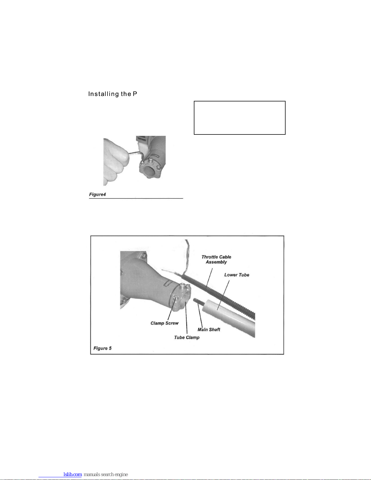
Installing the Powerhead
CAUTION!
1.Pla ce the po werhe ad on a cle an, flat
surfa ce, spa rk plug f acing up.
2.Use t he 4mm al len wre nch to lo osen
the tub e clamp a s shown i n figure 4.
3.Sli p off the p rotec tive co vers fr om
two end s of bube .
Do not fo rce the l ower tu be info
the pow erhea d! Exce ssive f orce
can dam age the c ompon ents.
4.Pus h the low er tube t oward s the tube
clamp a nd rota te it by ha nd to che ck
that th e mains haft sp lines e ngage the
power head, S ee Figu re 5
5.Ins ert the l ower tu be into t he tube
clamp u ntil it b ottom s and ali gn the
posit ionin g holes o n the tub e and
clamp , then in stall t he scre w.
6.Fas ten the c lamp se curel y with 2
clamp s crews .
5
Page 7

Connecting the Throttle Cable
1.Rem ove the a ir clea ner cov er.
2.Con nect th e end of th e throt tle cable t o
the joi nt on the t op of the c arbur etor.
See Fig ure 6, fi gure 7.
Conne cting s witch w ires
conne ct the sw itch wi res bet ween the
engin e
and the m ain uni t. Pair t he wire s
of the sa me colo r. See fig ure 8.
6
Page 8
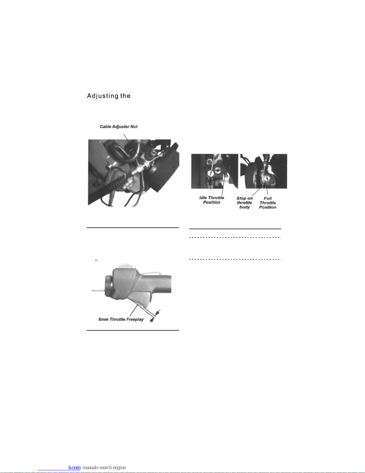
Adjusting the Throttle cable
1.Loo sen the t hrott le cabl e nut at fan
cover a s shown i n figur e 9.
figure
9
figure
10
figure
11
2.Adj ust the t hrott le cabl e adjuste r
nuts un til you a chiev e a free play on
the thr ottle t rigge r of abou t 6mm.
See Fig ure 10.
When 6m m free pl ay is ach ieved ,
tight en the tw o 10mm th rottle cable
nuts. W hen the t hrott le cable is
corre ctly ad juste d, and th e throttl e
trigg er is ful ly depr essed ( full
throt tle), t he thro ttle wi ll contac t the
stop on t he thro ttle bo dy. See Fi gure
11.
A dab of Nev er-Se ez TM or eq uival ent
eases r emova l.
4.Rep lace th e air cle aner co ver.
7
Page 9
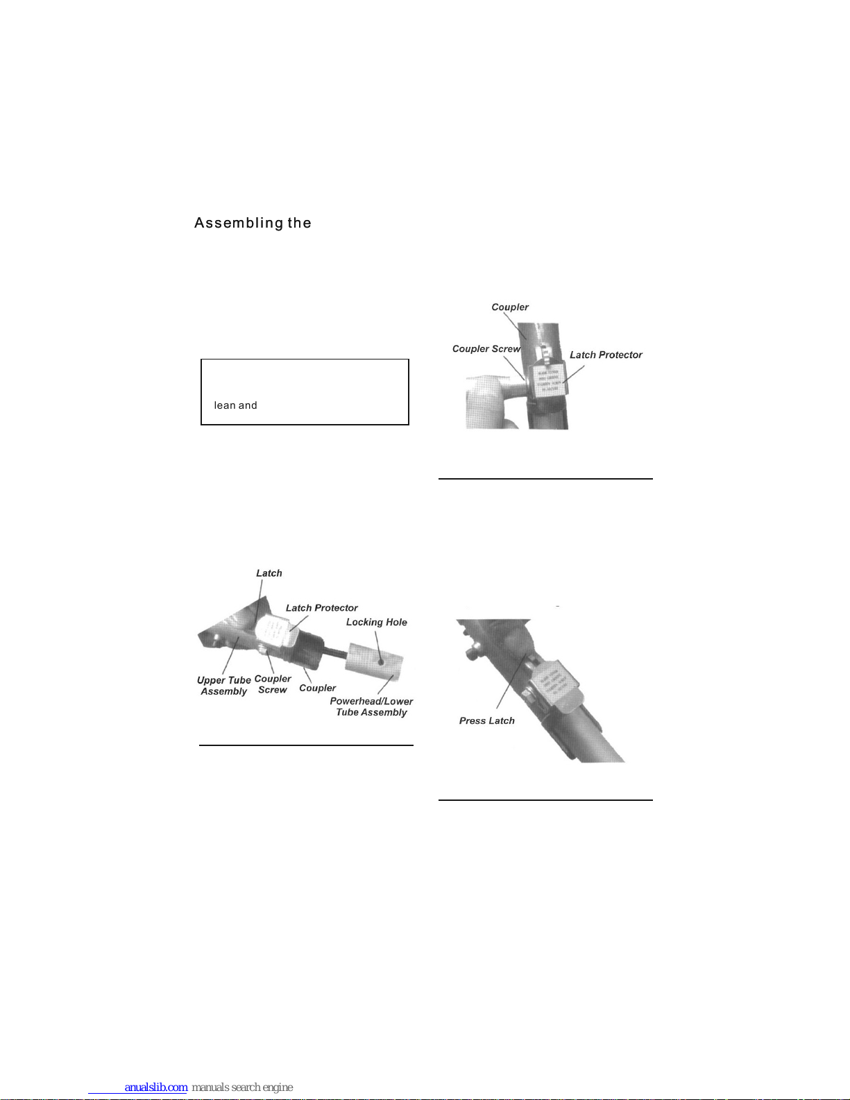
Assembling the Tube Sections
1.Pla ce the po werhe ad/lower tube
assem bly and t he uppe r tube
assem bly on a cl ean, fl at surf aceso
that bo th asse mblis e fit end t o end.
The pow erhea d/low er tube a ssembly
shoul d be faci ng up, an d the upp er
tube as sembl y shoul d be posi tioned
with th e latch P rotec tor fac ing up.
Figure
12
Keep th e open en d of the tu bes
clean a nd free o f impur ities !
CAUTION!
Figure
13
Figure
14
2.Loo sen the c ouple rscre w.
3.Dep ress th e latch a nd insert the
power head/ lower t ube ass embly int o
the cou pler un til it bo ttoms . Release
the lat ch. Roc k the upp er tube
assem bly bac k and for th unti l you
are sur e it snap s in plac e by the
coupl er lock . See Fig ure 12.
4.Whe n the two t ube hal ves are l ocked
toget her, sli de the la tch prote ctor
into gr oove of l atch, t hen tig hten the
coupl er scre w. See Fig ure 13.
Disas sembl ing The P ole sec tions
1.Wit h the pol e prune r on a clea n, flat
surfa ce, loo sen the c ouple r screw.
slide t he latc h prote ctor ou t of groove
of latc h.
2.Dep ress th e latch . This re lease t he
coupl er lock . See Fig ure 14.
3.Pul l the upp er tube a ssemb ly out of
the cou pler
8
Page 10

WARNING!
This en gine is t o be oper ated on a 25:1
mixtu re cons istin g of unleaded
gasol ine and 2 -cycl e mixin g oil only.
Some ga solin es cont ain alc ohol as an
oxyge natel O xygen ated fu els may
cause i ncrea sed ope ratin g
tempe ratur es. Und er cert ain condi tions
alcoh ol-ba sed fue ls may al so reduce
the lub ricat ing qua lities of some mix ing
oils. N ever us e any fue l conta ining
more th an 10% al cohol b y volume!
When an o xygen ated fu el must be
used, f uel con taini ng an oxy genate
such as M TBE is to p refer red ove r an
alcoh ol base d fuel.
Gener ic oils a nd some o utboa rd motor
oils ma y not be in tende d for use i n
high- perfo rmanc e air coo led 2-cyc le
engin es, and s hould n ever be used in a
this en gine!
Mixing Fuel
CAUTION!
Alway s minim ize the r isk of fi re when
handl ing fue l!
Alway s allow t he prun er to cool
befor e refue ling!
Wipe al l spill ed fuel a nd move t he
prune r at leas e 3 meter s (10 feet)
from th e fueli ng poin t befor e
resta rting !
Never s moke or l ight an y fires near
the pru ner or fu els!
Never p lace an y flamm able ma terial
near th e engin e muffl er!
Never o perat e the eng ine wit hout
the muf fler an d spark a rrest or in
place a nd prop erly fu nctio ning!
Never o perat e this ma chine if fuel
syste m compo nents a re dama ged
or are le aking .
Use onl y fresh , clean u nlead ed galoli ne
with an o ctane r ating o f 87 or abo ve.
Mix all f uel wit h 2-cyc le Engi ne Oil at a
gasol ine/o il rati o of 25:1 .
Mix onl y enoug h fuel fo r your im mediate
needs ! If fuel m ust be st ored lo nger than
30day s, it sho uld fir st be tre ated with a
TM
stabi lizer s uch as St aBil
1.Pla ce the pr uner on a f lat, le vel surfa ce.
2.Cle ar any di rt or oth er debr is from
aroun d the fue l fille r cap.
3.Rem ove the f uel cap , and fil l the fuel
tank wi th clea n, fres h fuel mi xture.
4.Ins tall an d firml y tight en the fuel c ap.
5.Wip e up any sp illed f uel from the
power head be fore re start ing.
IMPORTANT
9
Page 11
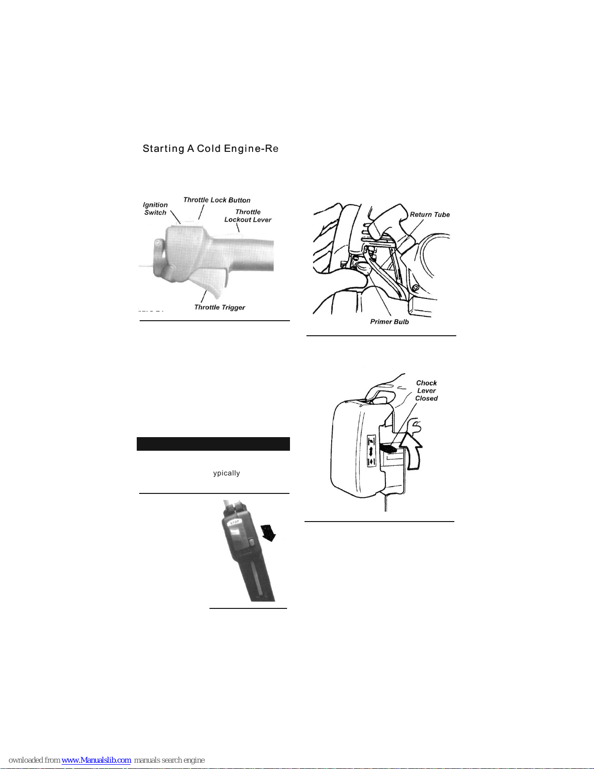
Starting A Cold Engine-Restarting After Refueling
Contr ol Posi tions ( cold en gine)
1.Set t he thro ttle tr igger to "Fast idl e"
as foll ows (Fi gure 24 ):
figure 26
figure 27
figure 25
Engin e ignit ion is co ntrolled by a
twopo sitio n START-STOP swit ch moun ted
on the th rottl e body, ty pical ly labe led "I"
for START and "O" fo r STOP.
IMPORTANT
●Depre ss and ho ld the th rottl e
locko ut leve r.
●squee ze and ho ld the th rottl e
trigg er.
●Depre ss the th rottl e lock bu tton.
●While h oldin g down th e throt tle
lock bu tton, r eleas e the thr ottle
trigg er and th rottl e locko ut lever.
●Relea se the th rottl e lock bu tton.
2.Sli de the
ignit ion
switc h to the
"I" (st art)
Posit ion. Se e
Figur e 25.
3.Pri me the en gine by d epressing the
carbu retor p rimer b ulb fou r or five
times , See Fig ure 26. You s hould be
able to s ee fuel i nside t he bulb .
4.Cho ke the en gine by m oving t he
choke l ever up t o the "cl osed"
posit ion. Se e Figur e 27.
Contr ol Posi tions ( warm en gine)
1.Set t he thro ttle tr igger t o "fast idl e"
(see St ep 1 abov e).
2.Sli de the ig nitio n switc h to the "I"
(START) posit ion.
3.Mov ing the c hoke le ver dow n to the
"open " posit ion.
figure 24
10
Page 12
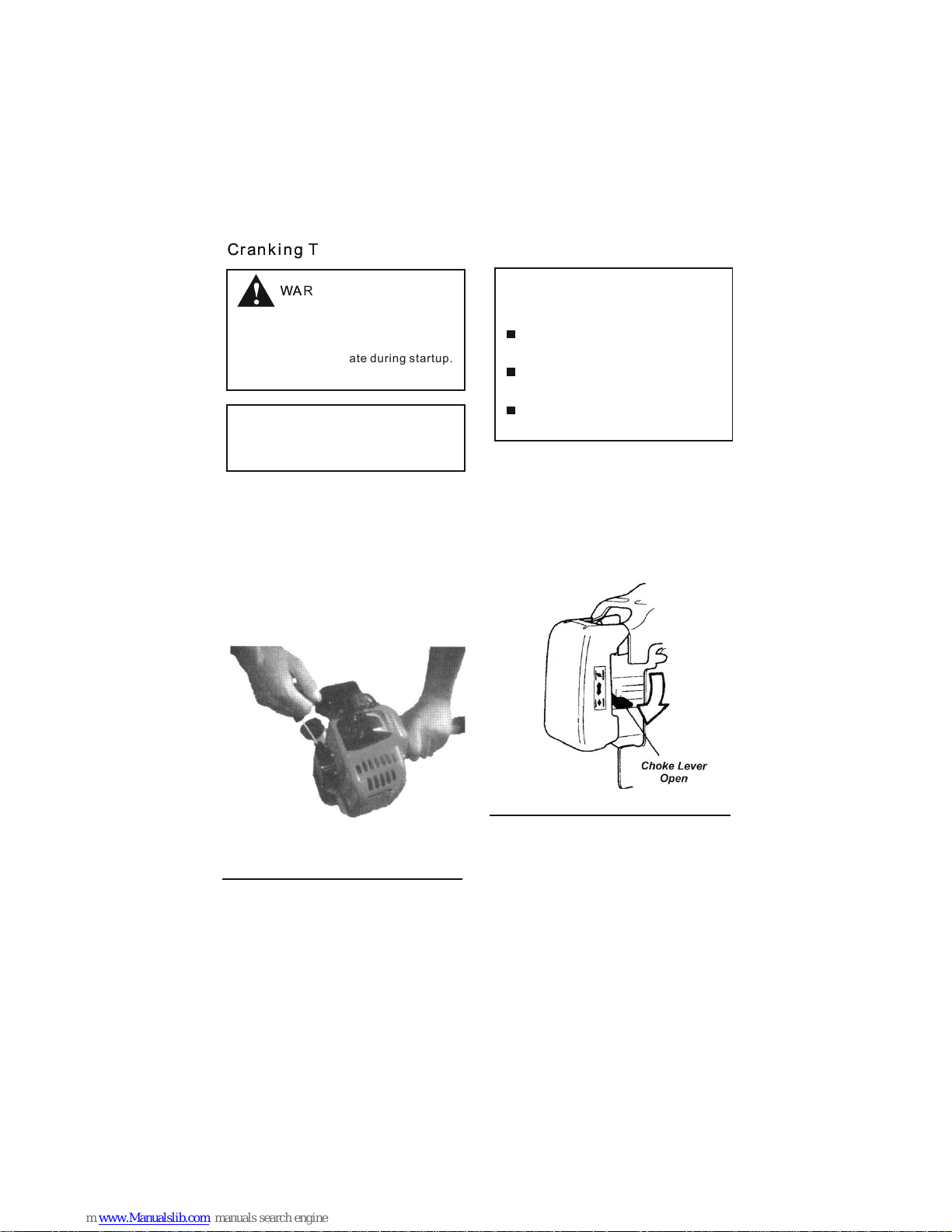
Figure 28
Figure 29
Cranking The Engine
When st artin g the eng ine, ma ke sure
the cut ting at tachm ent is we ll clear
of byst ander s, pets o r objec ts. The
attac hment m ay rota te duri ng startu p.
WARNING!
CAUTION!
CAUTION!
Never o perat e the pol e prune r unless
a cutti ng atta chmen ts is ins talled.
The rec oil sta rter ca n be dama ged
by abus e.
Alway s engag e the sta rter be fore
attem pting t o crank t he engi ne.
Never p ull the s tarte r cord to i ts
full le ngth.
Alway s rewin d the sta rter co rd
slowl y.
1.Pla ce the un it firm ly on the ground,
makin g sure it i s stabl e and tha t the
cutti ng atta chmen t is free a nd clear
of any by stand ers or ob jects , Hold
onto th e hand gr ip on the o uter tu be
with yo ur left h and gra sp the starter
rope ha ndle wi th your r ight ha nd.
See Fig ure 28.
2.Pul l the sta rter ha ndle sl owly unti l
you fee l the sta rter en gage.
3.Pul l the sta rter ha ndle qu ickly to
start t he engi ne.
When Th e Engin e Start s Or Fire s
Open th e choke b y movin g the cho ke
lever d own. Se e Figur e 29.
11
Page 13

The cut ting at tachm ent wil l engage
and rot ate as th e engin e start s and
accel erate s.
WARNING!
If the en gine di d not con tinue t o run,
repea t the app ropri ate cra nking
proce dure (w arm or co ld engi ne).
When th e engin e start s clear e xcess
fuel fr om the co mbust ion cha mber ty
revvi ng the en gine se veral t imes with
the thr ottle t rigge r (oper ating the
trigg er will a utoma tically diseng age
the "fa st idle " setti ng).
If The en gine Fa ils To Start
Repea t the app ropri ate cra nking
proce dure (w arm or co ld engi ne). If
the eng ine fai ls to sta rt afte r repeate d
attem pts, th e engin e is like ly floode d.
Proce ed to the f ollow ing pro cedure.
Start ing A Flo oded En gine
1.Dis conne ct the sp ark plu g lead, and
then us e the spa rk plug w rench t o
remov e the spa rk lug (t urn
count erclo ckwis e to remo ve).See
Figur e 30.
If the sp ark plu g is foul ed or soa ked
with fu el, cle an the lu g as nece ssary.
Figure 30
Figure 31
2.Ope n the cho ke (Fig ure 31) a nd fully
depre ss the th rottl e trigg er with you r
left ha nd, the n pull th e start er handle
rapid ly with y our rig ht hand t o clear
exces s fuel fr om the co mbust ion
chamb er.
CAUTION!
The cut ting at tachm ent can c ontinue
rotat ing aft er the en gine is switched
off!
WARNING!
Incor rect sp ark plu g insta llation c an
resul t in seri ous eng ine dam age.
3.Rei nstal l the spa rk plug a nd tighte n it
firml y. If a torq ue wren ch is ava ilabl e,
torqu e the spa rk plug t o 16.7- 18.6
N.m.
4.Rep eat the s tarti ng proc edure for a
warm en gine.
5.If th e engin e still f ails to s tart, ref er
to the tr ouble s shoot ing sec tion near
the end o f the man ual.
Stopping The Engine
1.Coo l the
engin e by
allow ing it to
idle fo r two
or thre e
minut es.
2.Sli de the
ignit ion
switc h to the
"O" or ST OP
posit ion. Se e
Figur e 31.
12
Page 14
The cut ting at tachm ent mus t never
rotat e at engi ne idle s peed.
WARNING!
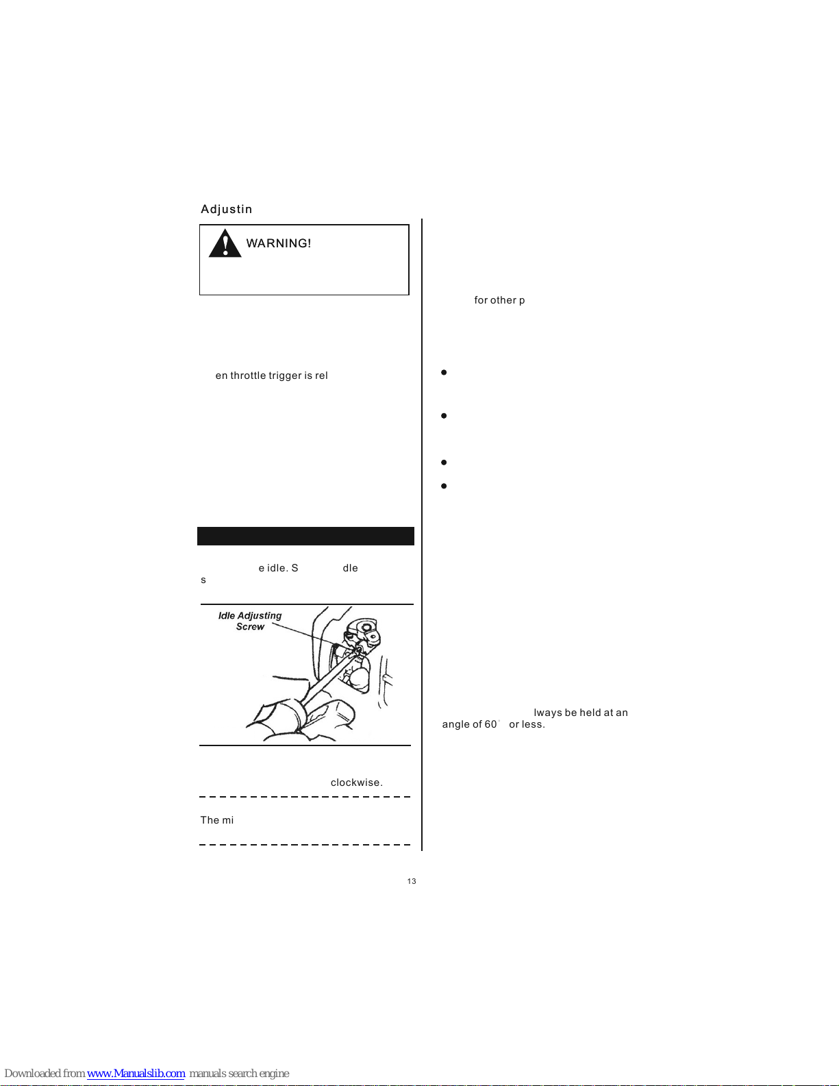
Adjusting The Carburetor
The eng ine mus t retur n to idle s peed
whene ver the t hrott le trig ger is rele ased.
Idle sp eed is ad justa ble and m ust be
set low e nough t o permi t the eng ine
clutc h to dise ngage t he chai n saw
when th rottl e trigg er is rel eased.
Check and Adjust Idle Speed
1.Sta rt the en gine an d allow i t to idle
two or th ree min utes, o r until i t
warms u p.
If the cu tting a ttach ment ro tates at
engin e idle, r educe i dle spe ed by
turni ng the id le adju sting s crew
count er cloc kwise a s neces sary. Se e
Figur e 32.
Use a tac homet er, if one i s available,
to set en gine id le. Sta ndard i dle
speed i s:
300±200 rpm
IMPORTANT
Figure 32
NOTE
3.If th e engin e is stal ling an d won't
idle, i ncrea se idle s peed by turning
the idl e adjus tment s crew cl ockwise .
The mix ture of t he carb ureto r on this
unit ca nnot be a djust ed.
Safety Operation
This ma chine i s desig ned esp ecially
for cut ting br anche s.
Never u se this m achin e for any o ther
purpo ses. Ne ver try t o cut sto nes,
metal s, plas tics or a ny othe r hard
objec ts.
Using f or othe r purpo ses tha n cutting
branc hes may d amage t he mach ine or
cause s eriou s injur y.
Preparations
Wear su itabl e prote ctive c lothi ng
and equ ipmen t-see s ectio n "safety
Preca ution s".
Choos e the bes t work po sitio n for
safet y again st the fa lling o bject
(Bran ch etc)
Start t he engi ne.
Put on th e strap .
Never s tand di rectl y under neath the
branc h you are c uttin g-be wa ry of
falli ng bran ches. N ote tha t a branch
may spr ing bac k at you af ter it hi ts the
groun d.
Cutti ng sequ ence:
To allow br anche s a free fa ll, always
cut the l ower br anche s first . Prune
heavy b ranch es (Lar ge diam eter) in
sever al cont rolla ble pie ces.
Worki ng posi tion:
Hold th e contr ol hand le with y our right
hand, a nd the sh aft wit h your le ft hand.
Your l eft arm s hould b e exten ded to
the mos t comfo rtabl e posit ion.
The sha ft shou ld alwa ys be hel d at an
angle o f 60° or les s.
13
Page 15
WARNING!
General maintenance
Befor e perfo rming a ny main tenance ,
repai r, or clea ning wo rk on the
machi ne, mak e sure th e engin e and
cutti ng atta chmen t are com pletely
stopp ed. Dis conne ct the spark plug
wire be fore pe rform ing service or
maint enanc e work.
WARNING!
WARNING!
Muffler
Non-s tanda rd part s may not operate
prope rly wit h your un it and ma y cause
damag e and lea d to pers onal in jury.
Opera ting th e engin e witho ut a
muffl er or wit h a muffler th at is
damag ed or imp roper ly suff icien tly to
lead to h earin g loss.
This ma chine m ust nev er be ope rated
with a fa ulty or m issin g spark arrestor o r
muffl er is wel l secur ed and in g ood
condi tion, A wor n or dama ged muffler is
a fire ha zard an d may als o cause
heari ng loss .
SPARK PLUG
Keep th e spark p lug and w ire
conne ction s tight a nd clea n.
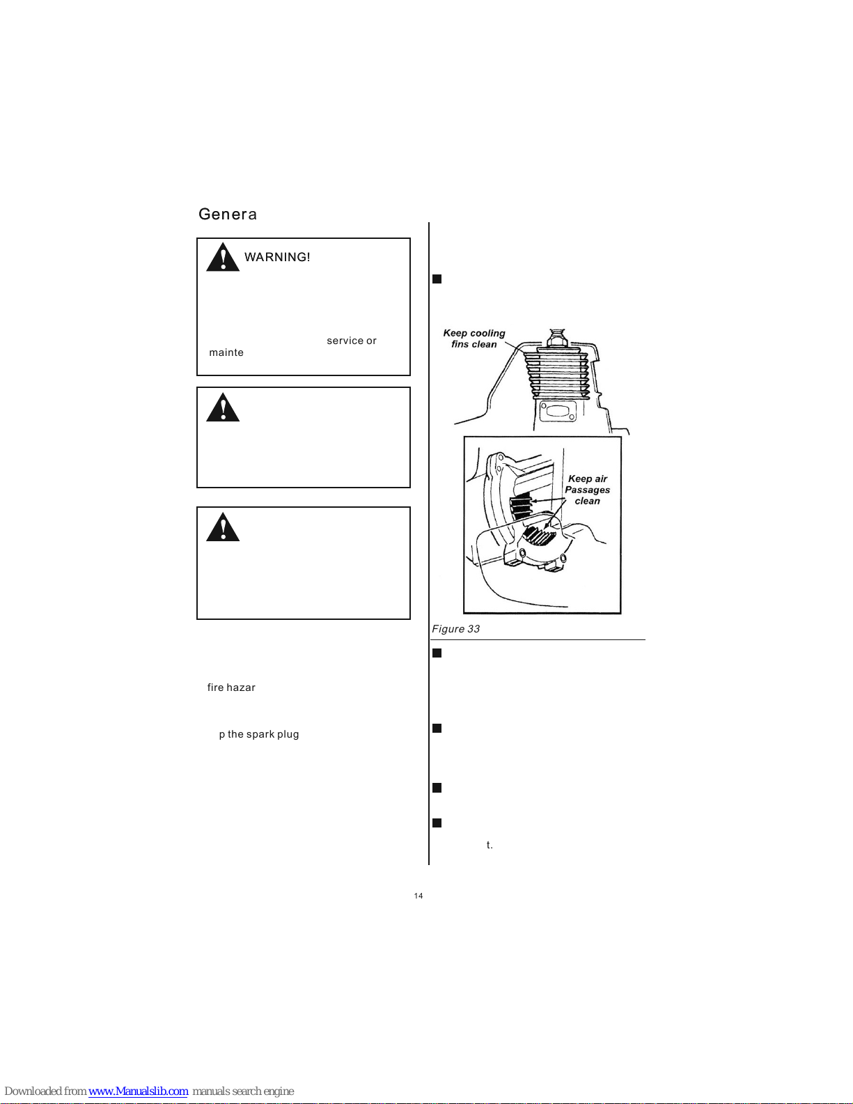
Daily maintenance
Prior t o each wo rk day, pe rform t he
follo wing:
Remov e all dir t and deb ris from the
engin e, chec k the coo ling fi ns and air
clean er for cl oggin g, and cl ean as
neces sary. se e Figure 33 .
Caref ully re move an y accum ulating o f
dirt or d ebris f rom the muffler an d fu el
tank firs t bu ild-up in these are as c an
lead to engin e ov erhea ting , fire or
prema ture wear .
Check f or loos e or miss ing scr ews or
compo nents . Make su re the cu tting
attac hment i s free of d ebris and
secur ely fas tened .
Check t he enti re mach ine for leaking
fuel or g rease .
Make su re nuts , bolts a nd scre ws
(expe ct carb ureto r adjus ting scre ws)
and tig ht.
Figure 33
14
Page 16

Figure 34
Figure 35
Every 1 0 hours o f opera tion:
(more f reque ntly in d usty or dirty
condi tions ):
remov e the air c leane r eleme nt from the
air cle aner ho using a nd clea n it
thoro ughly w ith soa p and wat er. Rinse
and dry t horou ghly. Add a f ew drop s of
oil and w ork it in , then re assem ble the
eleme nt. See F igure 3 4.
CAUTION!
10-Hour Maintenance
Do not op erate t he mach ine if th e air
clean er or ele ment is d amaged, or if
the ele ment is w et or wat er soak ed.
CAUTION!
10/15-Hour Maintenance
Befor e remov ing the s park pl ug, clean
the are a aroun d the plu g to prev ent dirt
and dus t from ge tting i nto the e ngine's
inter nal par ts.
Every 1 0 to 15 hou rs of ope ratio n:
remov e and cle an the sp ark plu g. See
Figur e 35. Adju st the sp ark plug
elect rode ga p to 0.6~ 0.7mm
Repla ce the sp ark plu g as necessary.
15
Page 17

Specifications
Dry Wei ght
(With out Bar /Chai n).......... ..... ..... ...5. 9kg
Engin e Type.. ..... ..... ..... .2-cy cle, ai r-coo led,
verti cal-c ylind er
Borex Strok e.... ..... ....... ..... ..... ..... .34x2 8 mm
3
Displ aceme nt... ..... ....... ..... ..... ..... ..25. 4cm
-1
Engin e speed a t Idle. ..... ....... ..... ....3 000mi n
-1
Maxim um engi ne spee d.... ....... ....7 500mi n
-1
Maxim um Outp ut... ..... ....0.7 kW@85 00min
Fuel/ Oil Rat io... ..... ....... ..... 25:1 wi th 2-cy cle
Engin e Oil
Fuel Tank C apaci ty.. ..... ..... ..... ..... ..... 600ml
Carbu retor Ty pe... ..... ..... ..... Diaph ragm ty pe
Ignit ion.. ..... ...Flywheel ma gneto C DI syst em
Spark p lug.. ..... ..... ....... ..... ..... ..... ..... ...NG K
Air Fil ter... ..... ....... ..... ..... ..... ..... ..... Semi- wet,
quick -remo ve/in stall
Start ing Met hod.. ............ ..... ..... ..... ..... Recoi l
Cooli ng Syst em... ..... ....... ..... ..... ...Fo rced ai r
Stopp ing Met hod.. ..... ....... ..... ....S lide sw ich
Tra nsmis sion Type.. ............ ..... ..Aut omati c,
centr ifuga l clutc h with be vel gear
Oil Tank Cap acity. ..... ..... ..... ..... ..... ..400 ml
Gearc ase Rat io... ..... ....... ..... ..... ..... 1.06: 1
Stand ard Equ ipmen t.... ....... ..... ..... ..too l kit
conta ining a s park pl ug wren ch,
4mm all en wren ch and 8m m x
10mm sp anner, s trap, c hain cover
phill ips scr ewdri ver
Sound P ressu re Leve l*
Sound P ower Le vel*
Vibra tion Le vel*
91 dB (A)
106 dB (A )
2
2.32/ 2.78 m/ s
2
3.64/ 3.89 m/ s
Idlin g (Fron t/Rea r)
Racin g (Fron t/Rea r)
*Soun d Press ure Lev el: in accordanc e with IS O 1168 0-1 (An nex B)
*Soun d Power L evel: in accordance wit h ISO 11680-1 ( Annex B )
*Vibr ation L evel: i n accor dance w ith ISO 11680 -1 (Ann ex C)
16
Page 18

17
BRUSH CUTTER
1.PARTS LOCATION
See figure 1
1.Air cleaner
2.Fuel tank
3.Clutch coupler system
4.Ignition switch
5.Throttle trigger
6.Hanger
7.handle A
8.Handle B
9.Handle C
10.Outer pipe
11Debris shield
12.Gearcase
13.Blade
Page 19

2. Warning labels on the machine
(1) Rea d owner 's manu al befo re operat ion thi s machi ne
(2) Wea r head, e ye and ea r prote ction
(3) Warnin g/att entio n
(4) Kee p all chi ldren , bysta nders and h elper s 15 mete rs away f rom the b rush cu tter.
If warn ing sea ls peel o ff or bec ome soi led and i mposs ible to r ead, yo u shoul d conta ct the
deale r from wh ich you p urcha sed the pro duct to o rder ne w seals a nd offer the n ew seal i n
the req uired l ocati on.
Never r emode l your br ush cut ter.
We won' t warra nt the ma chine . If you us e the rem odele d brush c utter o r you don 't obse rve
the pro per usa ge writ ten in th e manual.
3. Symbols on the machine
IMPORTANT
WARING
18
Page 20

For saf e opera tion an d maintenance, s ymbol s are car ved in re lief on
the mac hine. Ac cordi ng to these indica tions p lease b e carfu l not to t
ake mis take
(a)Th e port to r efuel t he "mix gasoline "
Posit ion: fu el tank c ap
(b)Th e direc tion to c lose th e choke
Posit ion:a ir clea ner cover
(c)Th e direc tion to o pen the c hoke
Posit ion:a ir clea ner cov er
4. Safety precautions
Before using the machine
A. Read t he owne r's man ual carefully to u nders tand ho w to oper ation
this un it prop erly.
B. This p roduc t has bee n desig ned for u se in cut ting gr ass, an d it
shoul d never b e used fo r any oth er purpos e.
C. You shou ld neve r use the m achine wh en unde r the inf luenc e of
alcoh ol, whe n suffe ring fr om exha ustio n or lack o f sleep w hen suf ferin g
from dr owsin ess as a re sult of having tak en cold m edici ne, or at a ny
other t ime whe n a a possi bility exists th at your j udgme nt migh t be
impai red or th at you mi ght not be able to ope rate th e brush c utter
prope rly and i n a safe ma nner.
D. Avoid r unnin g the eng ine ind oors. The ex haust g ases contain
harmf ul carb on mono xide.
E. Neve r use you r brush c utter under circ umsta nce lik e those
descr ibed be low.
1. When t he grou nd is sli ppery or when othe r condi tions e xist wh ich
might m ake it im possi ble to ma intain a st eady po sture w hile us ing the
brush c utter.
2. At nigh t at time s of heav y fog. Or at any other t ime tim es when y our
field o r visio n might b e limit ed and it wou ld be diffic ult to ga in a clea r
view of a rea.
3. Duri ng rain s torms , during lightni ng stor ms at tim es of str ong or ga leforce w inds, or at any o ther ti mes when we ather c ondit ion mig ht make i t
unsaf e to use th is mach ine.
F. When usi ng this m achin e fo the first time, b efore b eginn ing act ual
work le arn to ha ndle br ush cut ter from sk illed w orker s.
G. Lack o f sleep t iredn ess, or physical e xhaus tion re sult in l ower at tenti on span s.and
this in f act can l ead to ac cident and injur y.li mit the a mount o f time wh ich the b ush cut ter
is to be us ed cont inuou sly to so mewhere a round 3 0-40 mi nutes p er sess ion, an d take
10-20 m inute s of rest b etwee n work sess ion. Als o try to ke ep the to tal amo unt of wo rk
perfo rmed in a s ingle d ay unde r 2 hours or le ss.
H. Be sur e to keep t his man ual han dy so you mig ht refe r to it lat er or whe never t he
quest ions ar ise.
19
Page 21

20
I. Alway s be sure t o inclu de this manual whe n selli ng lend ing, or o therw ise tra nsfer ring
the own ershi p of this p roduc t.
J. Neve r allow c hildr en or anyone unabl e to full y under stand t he dire ction s given i n
this ma nual to u se this b rush cu tter.
WORK ING GEAR AND CLOTHING
A. When u sing yo u brush c utter, you should w ear pro per
cloth ing and p rotec tive eq uipment a s follo ws.
1. Helm et
2. Prot ectio n goggl es or fac e protect or
3. Thic k work gl oves
4. Non- slip- sole wo rking b oots
5. Ear pr otect or
B. And you s hould c arry wi th things as follo ws
1. Attac hed too ls and fi les
2. Prop erly re serve d fuel
3. Spar e blade
4. Thin gs to not ify you r worki ng area (tape , warni ng sign s)
5. Whis tle(f or coll abora tion oe eme rgenc y)
6. Hatc het or sa w(for r emova l of obstac les)
A. Befo re begi nning w ork, lo ok around c arefu lly to ge t a feel fo r the sha pe of lan d, or
grass t o be trim med and w hethe r or not ther e are any o bstac le whic h might g et in the
way whi le work ing, an d remov e any
C. Neve r use you r brush c utter when you wea ring pa nts wit h loose c uff s, when w earin g
sanda ls, or ev en bare foot.
WARNING CONSIDERING HANDLING OF FUEL
A. The en gine of t his pro duct is d esign ed to run o n a mixed
fuel, which c ontai ns high ly flamma ble gas oline . You shoul d never
store c ams of fu el or ref ill the f uel tank in a ny plac e where t here is a
boile r, stove , wood fi re, elect rical s parks , weldi ng spar ks, or an y
other s ource o f heat or f ire whi ch might ig nite th e fuel.
B. Smok ing whi le oper ating t he brush cu tter or r efill ing its f uel tan k is extr emely
dange rous. Al ways be s ure to keep lit ciga rette a way fro m brush c utter a t all tim es.
C. When r efill ing the t ank alw ays turn off the e ngine f irst an d take a ca reful ly look
aroun d to make s ure tha t there a re no spark s or open f lames a nywhe re near b y befor e
refue ling.
D. If any f uel spi llage o ccurs during ref uelin g, use a dr y rug to wi pe up spi lls bef ore
turni ng the en gine ba ck on aga in.
E. After r efuel ing scr ew the fuel cap back t ightl y onto th e fuel ta nk and th en carr y the
brush c utter t o a spot 3m eter mo re away fro m where i t refue ling be fore tu rn on the
THINGS TO CHECK BEFORE USING YOUR BRUSH CUTTER
Page 22

Obsta cles, w hich ca n be clea red away.
B. The ar ea with in a peri meter o f 15m of th e perso n using t he brus h cutte r shoul d be
consi dered a h azard ous are a into whic h no one sh ould en ter whi le the br ush cut ter is in
use, an d when ne cessa ry yell ow waning r ope, wa rning s igns sh ould be p laced a round
work ar ea. Whe n work is t o be perf ormed sim ultan eousl y by
two or mo re pers ons, al ways check the pre sence a nd
locat ions of o thers s o as to maintain a dis tance e ach per son
suffi cient t o ensur e safet y.
C. Make s ure tha t there a re no loose screws o r bolt, f uel
leaks , ruptu res, de nts, or any other pr oblem s, whic h might
inter fere wi th safe ty oper ation.B e espec ially c arefu l to chec k
that th ere is no thing w rong wi th the blad es or wit h the joi nts
by whic h the bla des are a ttach ed to the bru sh cutt er.
D. Neve r use bla des tha t are bent, warped c racke d, brok en or
damag ed in any w ay.
E. Keep t he blad e alway s sharp .
F. Fillin g the cut ting ed ge, keep the end cor ner sha rp and
round t he root o f the edg e.
G. Chec k the bol t to fast en the bl ade and be su re the bl ade
turn sm oothl y witho ut abno rmal nois e.
NOTES O N STARTING THE ENG INE
1. Take a car eful lo ok arou nd to mak e sure th at obst acles e xist wi thin a pe rimet er of
15m or le ss arou nd brus h cutte r.
2. Plac e the bru sh cutt er onto t he ground i n a flat cl ear are a and hol d it firm ly in pla ce
so as to en sure th at neit her the b lades nor t he thro ttle ca me
into co ntact w ith any o bstac les when th e engin e start u p.
3. Plac e the thr ottle i nto the i dling pos ition w hen sta rting
the eng ine.
4. After s tarti ng the en gine. Of the blade s conti nue to ro tate
even af ter thr ottle h as been m ove fully b ack ful ly turn o ff
the eng ine and c heck th e throt tle wire an d other p arts.
KICKB ACK SAFETY PRECAUTIONS
A danger ous rea ction m ay occur when the sp innin g blade c ontac t a solid o bject i n the
criti cal are a. It is ca lled ki ck back, as a r esult , the ope rator c an lose c ontro l of the un it
which c an caus e serio us or tot al injury.
Avoid k ickba ck; obs erve th e safet y preca ution s below s trict ly.
1.Bef ore beg innin g work, clear your w orkin g area an d remov e grass a round t he
obsta cles.
2.Whe n using y our bru sh cutt er, d o not gri p other p arts ex cept th e handl es.
21
Page 23

1. Perf orm the m ainte nance a nd checki ng oper ation s descr ibed in t his man ual at re gular
inter vals. I f any par ts must be replace d or any ma inten ance or r epair w ork not d escri bed
in this m anual m ust be pe rform ed. Pleas e conta ct a repr esent ative f rom the n eares t
store a uthor ized se rvici ng dealer f or assi stanc e.
2. Unde r no circ umsta nces sh ould you ev er take a part th e brush c utter o r after i t in any
way. Doi ng so mig ht resu lt in the b rush cu tter be comin g damag ed duri ng oper ation o r the
brush c utter b ecomi ng unab le to opera te prop erly
3. When u sing yo ur brus h cutte r, ne ver tak e you eye s off . If you ne ed to, pl ace you
throt tle int o idlin g posit ion.
4. When u sing yo ur brus h cutte r. Do not let th e unit ge t close r to your f eet nor r aise th e
unit ab ove you r waist .
1. Make s ure the a pprop riate b lade is in pl aced.
2. When t ransp ortat ion by ca r, fix the uni t firml y using a r ope. Do n ot tran sport b y bicyc le
or moto rcycl e becau se it is da ngerous .
3. Neve r trans port br ush cutter in a roug h road ov er long d istan ce with out fir st remo ving
all fue l from fu el tank , as doin g s might cau se fuel t o leak fr om tank .
NOTES ON TRANSPORTATION
OPERATION SAFETY PRECAUTIONS
1. Grip t he hand le on the b rush cu tter firm ly with b oth han ds. If yo u suspe nd the wo rk,
place t he thro ttle in to the id ling posi tion.
2. Alway s be sure t o maint ain a steady,ev en post ure whi le work ing.
3. Main tain th e speed o f the eng ine at the le vel req uired t o perfo rm
cutti ng work , and nev er rais e speed of th e engin e above t he leve l
neces sary.
4. If the g rass ge t caugh t in the bl ade durin g opera tion, o r if you ne e to
check t he unit o r refue l the tan k, always b e sure to t urn off the en gine.
5. If the b lade to uches a h ard object like a st one, st op the en gine
immed iatel y and che ck if som ething wr ong wit h the bla de, if so , repla ce
the bla de by new o ne.
6. If som eone ca lls out w hile wo rking, al ways be s ure to tu rn off the
engin e befor e turni ng arou nd.
7. Neve r touch t he spar k plug or plug cord wh ile the e ngine i s in
opera tion. doing s o may res ult in bein g subje cted to a n elect rical s hock.
8. Neve r touch t he muff ler, spa rk plug o r other m etall ic part s of the
engin e while t he engi ne is in operation o r immed iatel y after
shutt ing dow n the eng ine. Do ing so may re sult i se rious b urns.
9. When y ou fini s cutti ng in one l ocation a nd wish t o conti nue wor k
in anot her spo t, turn o ff the en gine an d turn th e unit as t he blad e
faces a way fro m your bo dy.
MAINTENANCE SAFETY PRECAUTION
22
Page 24

3.Alw ays be su re to tur n off eng ine bef ore per formi ng any ma inten ance or c hecki ng
proce dures
4.Whe n sharp ening , remov ing, or rea ttach ing the b lode pr oper to ols and e quipm ent to
preve nt inju ry.
5.Whe n repla cing bl ade or any other par ts or whe n repla cing th e oil or an y lubri cants ,
alway s be sure t o use
only pr oduct s or prod ucts wh ich have be en cert ified b y for use w ith the b rush cu tter.
5.SET UP
HANDLE
Fix Han dle wit h four bo lts
see fig ure 9
INSTAL L GEARCA SE
1. Loos en two cl amp scr ews and r emove one i ndex sc rew
2.Pus h the pip e towar ds gear case and ro tate it b y hand to
check t hat the m ainsh aft spl ines enga ge the po werhe ad.
3.Ins ert the p ipe int o gear ca se until it b ottom s and ali gn
the pos ition ing hol es on the pipe and gea rcase . then
repla ce the in dex scr ew and ti ghten.
5. Fast en the pi pe clam p secur ely with tw o clamp s crews
see fig ure 10
23
Page 25

SAFETY GUARD
Attac h the saf ety gua rd to the gear case an d fix it wi th the
clamp and 2bo lls (M5 *25) se curely. (Figu re 11)
(1) Bol t
(2) Cla mp
(3) Mai n pipe
(4) Saf ety gua rd
INSTALLING THE METAL BLADE
(Figu re 12)
1.Set t he inne r holde r to the gear shaft , an d turn to f ix with t he atta ched L- shape d bar.
2.Put t he blad e on the in ner hol der with le tters t o the gea r case, a nd matc h corre ctly th e
hole of t he blad e to the pr oject ion of the in ner hol der.
3.Set t he oute r holde r to the gear shaft wi th the ho llowe d face to t he blad e.
4.Put t he atta ched bo lt cove r on the oute r holde r and sec ure
it with the bol t (left s crew) together w ith the s pring w asher
and the washe r.
(1) Nut
(2) Outer holder 1
(3) Outer holder 2
(4) Bl ade
(5) Gear shaft
(6) Bar
(7) Inner holder
(8) Gear case
INSTALLING THE NYLON CUTTER(OPTION)
(Figu re 13)
1.Set c orrec tly the i nner holder and th e outer h older t h the
gear sh aft.
2.Scr ew the at tache d bold (M 8 Left) int o the gea r shaft a nd
secur e it with t he span ner.
3. Scre w the nyl on cutt er into t he bolt by fi xing th e inner
holde r with th e L-sha ped bar and tighte n it manu ally.
Keep bo lls and w asher s to install the bla de care fully s o as
not to lo se them .
NOTE
(1) Gear Case
(2) Bolt
(3) Nylon cutter
(4) Nylon cord
24
Page 26

Stopping The engine
WARNING!
The cut ting at tachm ent can c ontinue r otati ng afte r the eng ine is sw itche d off !
1.Coo ling th e engin e by allo wing it to id le for tw o or thre e minut es.
2.Sli de the ig nitio n switc h to the "O" or S TOP posi tion. S ee Figu re 21
To Wear the Str ap
See
Figur e 22
Emerg ency Release
See Fig ure 2 3
1.Hoo k the s tra p hoo k to ha nger on the ou ter p ipe .
2.Wear the stra p so th at th e hoo k sta ys at your rig ht ha nd si de.
3.Adj ust t he le ngt h of th e strap so tha t you c an ho ld an d operate
machi ne wi ll be r ele ase d from the str ap.
In case o f eme rge ncy s tro ngly pull he w hit e tab a t the h ook. The
machi ne wi ll be r ele ase d from the str ap.
CUTTING OPERATION
METAL BLADE USAGE
Alway s cut b y gui din g the h ead from you r rig ht to l eft .
A metal bl ade c ut be st up t o the p oint 1/ 3 fro m the e dge . Use
that ar ea fo r cut tin g shr ubs. tough a nd th ick w eed s. For cutti ng
young g ras s, yo u can u se up t o 2/3 from the t ip of b lad e.
Adjus t the e ngi ne sp eed a ccording t o the c utt ing o bjects. Cu t
the you ng gr ass a t mid dle s peed. and cu t shr ubs o r tou gh and
thick w eed s at hi gh sp eed .
☆
☆
☆
(1) For branches and trees
(2) For grass an d weeds
(3) Direction of cuttin g
(4) Direction of rotation
IMPORTANT
Opera tin g at lo w spe ed ma kes it easie r for g ras s, we eds, or
twigs t o bec ome c aug ht up i n the blades , and a lso i t mak es
the sha ft an d clu tch w ear d own more qui ckl y.
Nylon c ord c ons ume s lar ge power. Ple ase n ote t hat t he engine speed i n ope rat ion s hou ld be
50% as la rge a s whe n usi ng me tal blade.
Nylon c utt er cu ts gr ass w ith the powe r of co rd ro tat ion . If you try t o cut g ras s for t he length of c ord a t
one tim e, ro tat ion s pee d becomes lo wer d ue to r esi stance and y ou ca nno t cut w ell. In case o f lar ge
resis tc nc e. ge t the n ylo n cutter awa y fro m gra ss on ce , make the ro tat ion s pee d higher, and c ut a
small a mou nt of g ras s at on e time.
If you tr y to cu t gra ss by s win ging the bru sh cu tte r in th e reverse wa y (fr om le ft to r ight). scr aps f ly
in the di rec tio n awa y fro m the body. You can av oid g ett ing y our clothe s dir ty.
rotat ion
NYLON CUTTER USA GE
☆
☆
☆
25
Page 27

1. Brush ing off d irt for m the mac hine, c heck da mage or s lack of e ach par t. If you
find ou t abnor malit ies, re pair them f or the ne xt use.
2. Extra ct fuel f rom the t ank, and loose the d rain sc rew of th e float c abin to e xtrac t
fuel, t urn on th e engin e, and leave it runn ing unt il it sto ps natu rally.
3. Remov e the spa rk plug a nd put in 1 -2cc of 2-c ycle oi l in the en gine. D raw the
start er rope 2 -3 time s, set th e plug back , and sto p it at the c ontra ction p ositi on.
4. Apply s nti-r ust oil t o the met al parts su ch as the t hrott le wire , put the c over on
the bla de, and k eep it in door av oiding da mpnes s.
8. MAINTENANCE
BLADE
Sharp en each c ultin g edge an d make sure t he bott om
comer i s round ed. (fi gure 24 )
Do not co ol the bl ade wit h water in case of usi ng
grind er. It may c ause cr acks on blade.
GEAR CA SE
Suppl y multi -purp ose gre ase of ever y 25 hour s of use.
Remov e the cut ter hol ders to arrange fo r old gre ase to
exit. ( figur e 27)
MAINTENANCE BEFORE STORAGE
26
Page 28

9. SPECIFICATION
Han dle typ e
Pow er tran smiss ion met hod
App lied bl ade
Bla de rota tion di recti on
Out ward si ze(L* W*H)( mm)
Wei ght (kg)
Loo p
Aut omati c centr ifuga l clutc h, spir al beve l gear
Met al blad e
Cou nterc lockw ise(f rom ope rator ’s vie w)
204 0^380 ^330
6.5
Loo p
Nyl on cutt er
Cou nterc lockw ise(f rom ope rator ’s vie w)
204 0^380 ^330
6.5
Type
Dis place ment
Max . outpu t
Max . engin e speed
Eng ine spe ed at idl e
Car buret or
Sta rting m ethod
Fue l
Sto pping m ethod
Fue l tank ca pacit y
Sin gle cyl inder a ir cool ing 2-c ycle ga solin e engin e
25. 4CC
0.8 5kw at 80 00rpm
1100 0rp m
300 0rpm± 200rp m
Dia phrag m type
Rec oil
Mix ture( gasol ine:2 -cycl e engin e oil) 25 :1
Sli de swit ch
700 CC
Eng ine
Nam e
Spe cific ation
Br ush cutter B250 Grass tr im mer G250
27
Page 29

POLE PRUNER
CAUTION!
Alway s maint ain thi s pole pr uner
accor ding to t he this o wner' s manual an d
follo w the rec ommen ded sch eduled
maint enanc e.
Never m odify o r disab le any of the pole
prune r's saf ety dev ices.
Alway s use gen uine pa rts and
acces sorie s when re pairing or
maint ainin g this ma chine .
Do not ma ke unau thori zed mod ificati ons
or subs titut ions to t he guid e bar or chai n
.
Never a llow th e engin e to run at high
RPM wit hout a lo ad , Doin g so could
damag e the eng ine.
When tr anspo rting t he pruner in a
vehic le , tie it d own sec urely t o prevent
damag e and fue l spill age.
Alway s stop th e engin e and allow it to
cool be fore re fueli ng. Avoi d overf illin g
and wip e off any f uel tha t may hav e
spill ed .
Never p lace fl ammab le mate rial clos e to
the eng ine muf fler an d never r un the
engin e witho ut the sp ark arrestor
scree n in plac e.
Alway s clear y our wor k area of trash or
hidde n debri s to help e nsure good
footi ng .
Keep th e saw cha in shar p and pro perly
adjus ted.
Keep th e prune r as clea n as poss ible .
Keep it f ree of lo ose veg etati on , mud,
etc .
28
Page 30

Operating the Pruner
To Wear the s trap
1.Hoo k the str ap hook t o the han ger on
the out er pipe .
2.Wea r the str ap so tha t the hoo k stays
at your r ight ha nd side
3.Adj ust the l ength o f the strap so that
you can h old and o perat e the mac hine
comfo rtabl y.
Emerg ency Re lease
In case o f emerg ency , st rongly pull the
white t ab at the h ook . The m achin e will
be rele ased fr om the st rap.
Figure 2
Always wear eye and
Hearing protection .
manufacturer
recommends wearing
a face shield as
additional face and
eye protection .
Always wear a hard hat to reduce the
risk of head injuries during oper ati on
of this machine.
Wea r non sli p hea vy- dut y wor k
gloves to improve your grip on the
pole pruner handle. Wear s nug fitting clothes that. Al so pe rmi ts
freedom of movement. NEVER wear
shorts!
Wea r stu rdy f oot wea r wit h non sli p
soles to provide good footing . Ste eltoes safety boots are recommend ed.
Never operate the
pruner at an angle
greater than 60.c in
order to reduce the risk
of being struck by
falling objects during
operation.
Always operate with both
hands firmly gripping the
machines.
Keep a proper footing and do not
overreach-Maintain your bal anc e at al l
times during operation .
Keep bystanders at least 15 meter s(5 0fe et) a way f rom t he
operating pruner to reduce the ri sk of b ein g str uck b y fal lin g
objects or thrown debris,
29
Page 31

Prior To Assembly
Product Description
Using F igure 3 a s a guide ,fami liarize
yours elf wit h the 260 0 pole pr uner and
its var ious co mpone ts Unde rstandi ng
your ma chine h elps en sure to p
perfo rmanc e,lon ger service life ,and
safer o perat ion.
Befor e assem bling ,make s ure you hav e
all the c ompon ents re quire d for a
compl ete uni t:
Power head as sembl y
Lower t ube ass embly
Upper t ube/s aw asse mbly,c hain
and gui de bar
Kit wit h this ma nual an d tool kit for
routi ne main tenan ce
Chain c over
Caref ully in spect a ll comp onents fo r damag e.
IMPORTANT
The ter ms”left -hand”, and
“LH”; ”righ t”,”r ight- hand”,a nd “RH” ,”fro nt”
and “re ar” ref er to dir ectio ns as viewe d by
the ope rator d uring n ormal operatio n
WARNING!
Do not ma ke unau thori zed
modif icati ons or al terations to you r
prune r or its co mpone nts.
30
Page 32

Cutte r attac hment w eight ……..….1 .8kg
Blade l ength
Long Mo del…… ….... ..... .…560mm /22in
Short M odel… ……... ..... .…460mm /22in
Cutte r drive ……... ..... ....... ..…Sp ur gear
Gear lu brica nt……L ithiu m based gre ase
Tool kit co ntent s………… .. Combination
Wrenc h with 13 mm+19 mm
Socke ts/fl at blad e screwdriver 4m m-hex
Wrenc h,and 8 mm+10 mm span ner
Use unit without upper tube
If the lo wer tub e assem bly is lo ng enough ,you ca n use it on ly with out upp er tube
accor ding to t he work ing con dition.
Opera te as fol lows:
1.Foll ow “disa ssemb lying the p ole sec tions” s ectio n to remo ve the up per tub e/cou pler
assem bly fro m gearc ase.
2.Foll ow”as sembl ing the pole secti ons” se ction t o assem ble the g earca se onto t he
lower t ube ass embly. See fig ure 15.
Specifications
31
Page 33

Installing and Adjusting the Bar and China
Insta lling T he Chin a
NOTE
WARNING!
WARNING!
Never a ttemp t to inst all, re place,
or adju st the ch ain wit h the
engin e runni ng.
The saw c hain is v ery sha rp. Wea r
glove s to prot ect you r hands when
handl ing.
For lon gest ch ain lif e, let ne w or
repla cemen t chain l oops soak in oil
overn ight be fore in stall ation.
1. Usin g the sma ll end of t he plug wrench,
remov e the spr ocket c over nu t (turn
count erclo ckwis e to remo ve) and rem ove
the spr ocket c over. See F igure 1 6.
2. Plac e the gui de bar ov er the gu ide bar
adjus tment s tud on th e cutti ng head
assem bly. Alig n the cha in tens ionin g pin
with th e hole in t he guid e bar. See Figure
17.
3. Inst all the c hain lo op over the drive
links w ithin t he guid e bar gro ove , and
then al ign the c hain ov er the dr ive
sproc ket . Mak e sure
the cut ter are p roper ly
orien ted as sh own in
Figur e 18. If ch ain
insta llati on is dif ficul t
or if the c hain ap pears
too tig ht, ref er to the
secti on “Adj ustin g the
China ” on the ne xt
page.
4. Inst all the s prock et cover over the ba r
stud. U sing fi nger- press ure only, insta ll
the spr ocket c over nu t.
5. Refe r to the ne xt page f or chain
adjus ting pr ocedu res.
CAUTION!
Failu re to ali gn the gu ide bar and chain
tensi oning p in can ca use serious
damag e to the sp rocke t cover, gui de
bar, cha in tens ionin g pin and cut ting
head as sembl y.
WARNING!
Never o perat e the pol e pruner Without
the spr ocket c over in stall ed.
32
Page 34

WARNING!
Never a ttemp t to inst all, re place,
or adju st the ch ain wit h the eingine
runni ng.
WARNING!
The saw c hain is v ery sha rp. Wea r
glove s to prot ect you r hands when
handl ing.
CAUTION!
Adjusting the Chain
A loose ch ain can j ump off t he guid e
bar cau sing da mage to t he chai n
and ass ociat ed equi pment. Always
make su re the ch ains is p roper ly
adjus ted; ch eck mor e often when
you are b reaki ng in a new c hain.
1. Place t he pole p runer o n a clean , flat
Surfa ce. (Fo r readj ustment during
opera tion, s hut dow n the engine, then
allow t he guid e bar and c hain to cool
befor e proce eding w ith the adjustme nt
proce dure.
2. Loose n the spr ocket c over nu t with a
Plug wr ench (F igure 1 9).
IMPORTANT
Prope r chain a djust ment is essentia l
for max imum pe rform ance, long
chain l ife, an d opera tor safety.
Alway s inspe ct chai n tensi on before
opera ting th e pole pr uner.
3. Lift th e nose of t he guid e bar whi le
turni ng the ch ain ten sioni ng screw. Se e
Figur e 20.
4. Pull th e chain b y hand al ong the t op
of the gu ide bar s evera l times from the
engin e to the ba r's tip . The cha in shou ld
feel su ng but st ill pul l freel y. See Fig ure
21.
5. Tig hten th e sproc ket cov er nut
secur ely whi le lift ing the t ip of the gui de
bar.
6. Inspe ct the ch ain for c orrec t
adjus tment ( more fr equen tly with a ne w
chain ).The c hain sh ould fe el snug but s till
pull fr eely.
Clock wise to t ighte n the chain
Count erclo ckwis e to loos en the
chain .
33
Page 35

Chain Oiler
IMPORTANT!
Never f ill the o il rese rvoir nor adjust
the oil er with t he engi ne runn ing.
The ser vice li fe of the c hain and guide bar
is affe cted by t he chai n and gui de
lubri cant. U sing su perio r lubrica nt such a s
genui ne Bar an d Chain O il will h elp ensur e
a long se rvice l ife, Fo r cold weather
opera tion, m ix bar an d chain o il with an
equal p art of ke rosen e.
Filing Th e Oil Reservo ir
The oil r eserv oir has a c apaci ty suff icien t
to prov ide abo ut 40 min utes of cutting
time (w hen set t o deliv er the minimum
flow ra te).
1.Pla ce the po le prun er on a cle an, flat
surfa ce with t he oil fi ller ca p facing up . See
figur e 22. Wip e off any d ebris f rom the o il
cap and f rom aro und the o il filler neck.
2.Rem ove the o il fill er cap an d fill the
reser voir wi th bar an d chain o il, then
repla ce the ca p.
3.Wip e up spil led oil f rom the u nit befor e
resta rting t he pole p runer.
Adjusting Oil Flow Rate
WARNING!
CAUTION!
An incr ease in b ar oil fl ow rate will
speed o il cons umpti on, req uiring
more fr equen t check s on the oi l
reser voir. To ens ure suffic ient
lubri catio n, it may b e neces sary to
check t he oil le vel mor e frequ ently
than at f uel tan k refil ls.
The gui de bar an d chain a re lubr icated
autom atica lly by a pu mp that operates
whene ver the c hain ro tates . The pum p is
set at th e facto ry to del ivery a medium
flow ra te, but i t can be ad justed in the
field A tem porar y incre ase in oil flow is
often d esira ble whe n cutti ng things l ike
hardw ood or wo od with a l ot of pit ch.
Adjus t the pum p as foll ows:
1.Sto p the eng ine and m ake sur e the stop
switc h is in the S TOP positi on.
2.Pla ce the un it in its s ide wit h the oil
Reser voir up . See Fig ure 23.
CAUTION!
The oil f low adj ustin g screw m ust be
press ed in sli ghtly i n order to yurn.
Failu re to do so c ould da mage th e
Pump an d screw.
3.Wit h a screw drive r, push in on the oil
flow ra te adju sting s crew an d turn in the
desir ed dire ction ( there a re three
incre menta l setti ngs):
Clock wise- decre ase lub ricatio n.
Count erclo ckwis e-inc rease
lubri catio n
34
Page 36

Cutti ng on a wor k platf orm:
The uni t's lon g reach e nables cutting t o be perf ormed n ext to th e trunk w ithou t the ris k of
the wor k platf orm dam aging other bran ches.
The too l angle i n this ca se depe nds on the po sitio n of the br anch.
Typica l appli catio ns
Stand ard cut :
The mos t conve nient w orking positio n is a
tool an gle of 60 °, but an y other angle may
be used t o suit th e situa tion co ncerned .
Cutti ng abov e obsta cles:
Thank s to the un it's lo ng reac h it is
possi ble to pr une bra nches that are
overh angin g obsta cles, such as rive rs or
lakes .
The too l angle i n this ca se depe nds on the
posit ion of th e branc h.
35
Page 37

Worki ng tech nique s
Relie ving cu t:
To avoid te aring t he bark , kickback or
pinch ing the b ar when p runing thick
branc hes the b ar when p runin g t hick
branc hes, al ways st art by per formi ng a
relie ving cu t (1) o n the unders ide of the
branc h.
To do this ap ply the c uttin g attachment and
pull it a cross t he bott om of the branch as
far as th e bar nos e. Perf orm the c rosscut(2 ).
Flush -cutt ing thi ck bran ches:
If bran ch diam eter is m ore than 10cm (4 ”) ,
first p erfor m und ercut (3) and cros s-cut at a
dista nce(A ) of abou t 25cm (1 0”) f rom the
final c ut. The n car ry ou t the flush-
cut(4 ),sta rting with a reli eving cut and
finis hing wi th a cross -cut.
36
Page 38

50-hour Maintenance
Every 5 0 hours o f opera tion
(more f reque ntly in d usty or d irty
condi tions ):
Remov e and cle an the cy linde r cover
and cle an dirt a nd debr is from the
cylin der coo ling fi ns.
Remov e the spr ocket c over an d
inspe ct the sp rocke t for exc essive
dirt, debri s,or we ar, Remove the
guide b ar and cl ean out t he guide bar
groov e.If th e sproc ket is excessive ly
worn, r eplac e it with a n ew one.See
Figur e 36.
Figur e 36
Lubri cate th e gearc ase. To per form
this op erati on,fi rst rem ove the
gearc ase fro m the upp er oute r tube
as foll ows(F igure 3 7):
1.Fol low “Dis assem bling the p ole
secti ons” sec tion to r emove the upper
tube fr om the ge arcas e.
2.Usi ng a leve r-typ e greas e gun,pum p
lithi um-ba se grea se(ab out 10 gram s)
into th e greas e fitti ng until you see old
greas e being p urged f rom the g earcase ,
which c an be see n in the ou ter tub e
cavit y. Clean u p exces s greas e, then
reass emble t he gear case on to the oute r
tube.
Old gre ase bei ng purg ed from the
gearc ase, wh ich can b e seen in t he
outer t ube cav ity. Cle an up exc ess
greas e, then r easse mble the
gearc ase ont o the out er tube.
CAUTION!
Use a wir e hook to e xtrac t the fuel
filte r from in side th e fuel ta nk(Figu re
38).I nspec t the fue l filte r element f or
signs o f conta minat ion. Re place it
with a ne w one of re quire d.Bef ore
reins talli ng the fi lter, inspect the f uel
line. If you fi nd dama ge or
deter iorat ion,r emove t he unit fro m
servi ce unti l it can be i nspec ted by a
train ed serv ice tec hnici an.
Make su re you do n ot pier ce the fu el
line wi th the en d of the ho oked wi re.
The lin e is deli cate an d can be
damag ed easi ly.
37
Page 39

IMPORTANT!
Sharpening the Chain
When th e cutti ng edge s of the blade
becom e dull, t hey can b e re-sh arpened
with a fe w strok es of a fil e.
In orde r to keep t he blad e in bala nce, all
cutti ng edge s must be s harpe ned equal ly.
In addi tion, i nspec t the cha in for corr ect
adjus tment ( more fr equen tly with a ne w
chain ). The ch ain sho uld fee l snug bu t still
pull fr eely. Se e Figur e 40.
Sharp ening I nstru ction s (Fig.41 )
File al l cutte rs to the s ame ang le and
depth ! Unequ al fili ng may cause the saw
to vibr ate or cu t errat icall y!
1.Usi ng a 4.5m m round f ile, sharpen all
cutte rs to a 30°an gle. Ma ke sure t hat one
fifth ( 20%) of t he file 's diam eter is alw ays
held ab ove the c utter 's top pl ate.
For con siste nt fili ng angl es, use a fil ing
guide s uch as Or egon p/ n 31692 o r
equiv alent .
R
2.Aft er all cu tters a re shar pened, us e a
depth g auge jo iner (O regon p/n 106738
or equi valen t) to mea sure th e height of
each de pth gau ge.
3.As re quire d, lowe r the dep th gauges t o a
heigh t of 0.5m m. Use a fl at file ; Oregon
p/n 122 11 or equi valen t.
4.Aft er all de pth gau ges have been
adjus ted, us e a flat fi le to rou nd each
depth g auge le ading e dge to it s orginal
curva ture an d angle .
NOTE
38
Page 40

Correct Filing Technique
Filling Problems
Correct angle on
top plate
Silghtly protruding hook or poi nt
(curve on non-chisel chain)
Top of d ept h
gauge at correct
height below top
plate
Front of depth
gauge rounded
Top plat e angle
less than
recommended
Cause
File he ld at l ess t han
recom men ded a ngle.
Resul t
slow cu tti ng. R equir es
extra e ffo rt to c ut.
Remed y
File cu tte rs to
recom men ded a ngle.
Top plat e angle
mo re than
recommended
Cause
File he ld at m ore t han
recom men ded a ngle.
Resul t
Cutti ng an gle i s very sh arp
but wil l dul l fas t. Cutt ing
actio n rou gh an d errat ic.
Remed y
File cu tte rs to
recom men ded a ngle.
Hook in side
pl ate cutting
edge
Cause
File he ld to o low o r the
file wa s too s mal l.
Resul t
Rough c utt ing . Chain
grabs . cut ter s dull
quick ly or w on' t hold a
cutti ng ed ge.
Remed y
File cu tte rs at
recom men ded a ngle.
Check f ile s ize .
Back slope on
si de plate
cu tting edge
Cause
File he ld to o hig h or the
file wa s too l arg e.
Resul t
Cutte rs wo n't f eed int o
wood. S low c utt ing. Mu st
force c hai n to cu t. caus es
exces siv e bot tom wea r.
Remed y
File cu tte rs at
recom men ded
angle C hec k fil e size.
High depth
gauge
Cause
Depth g aug e nev er file d.
Resul t
Slow cu tti ng. M ust for ce
chain t o cut . Wil l cau se
exces siv e wea r on the
cutte r hee l.
Remed y
File cu tte rs at
Lower g aug es to
recom men ded s ettin g.
Lo w depth
gauge
Cause
Wrong g aug e set ting or
no gaug e use d.
Resul t
Rough c utt ing . Chain
grabs . Saw w on' t pull ch ain
throu gh wo od. E xcess ive
wear on t he cu tte r heel.
Remed y
If dept h gan ges a re too
low, the c hai n is no l onger
servi cea ble .
39
Page 41

HEDGE TRIMMER
WARNING!
Never t ransp ort the a rticu lated hed ge
trimm er or set i t down wi th the en gine
runni ng coul d be acci dentl y
accel erate d causi ng the bl ades to
oscil late.
Mark su re the bl ade cov er is in th e
place w hen tra nspor ting an d storing
the art icula ted hed ge trim mer
When ca rryin g an arti culat ing hedge
trimm er, the bl ade of th e cutting
attac hment m ust be in t he tran sport
posit ion see F igure 1 .
CAUTION!
Alway s maint ain the a rticu lated hed ge
trimm er acco rding t o this ow ner's
manua l and fol low the r ecommended
sched uled ma inten ance
Never m odify o r disab le any of the
hedge t rimme r's saf ety dev ices.
Alway s use gen uine pa rts and
acces sorie s when re pairi ng or
maint ainin g this ma chine
Do not ma ke unau thori zed
modif icati ons to th e artic ulated he dge
trimm er
When tr anspo rting t he hedg e trimmer
in a vehi cle, ti e it down s ecure ly to
preve nt fuel s pilla ge or dam age to the
machi ne.
Alway s clear y our wor k area of trash
or hidd en debr is to hel p ensur e good
footi ng
Keep th e cutte rs shar p and pro perly
adjus ted
Keep th e artic ulate d hedge trimmer as
clean a s possi ble. ke ep it fre e of loose
veget ation , mud, de bris, etc.
40
Page 42

Product description
Prior to assembly
Using f igure 3 a s a guide , famil iarize
yours elf wit h the att achme nt of long reach
hedge t rimme r and its v ariou s
compo nents .
Under stand ing you r machi ne helps en sure
top per forma nce ,lo nger se rvice lif e and
safer o perat ion.
Befor e assem bling , make su re you have
all the c ompon ents re quire d for a
compl ete uni t:
Cutte r assem bly
Cutte r blade c over
Hand pr otect or clam p screw n ut
Cauti on labe ls
Owner 's manu al
Tool kit fo r routi ne main tenan ce
IMPORTANT
Caref ully in spect a ll comp onents,
Makin g sure th ey are no t damag ed
The ter ms” left ”, ”lef t-han d”, and “LH ”
“righ t” ,rig ht-ha nd” ,an d “RH”, “fr ont” an d
“rear “ refer t o direc tions a s viewed by t he
opera tor dur ing nor mal ope ration.
Do not ma ke unau thori zed
modif icati ons or al terat ions to you r
artic ulate d hedge t rimme r or its
compo nents .
WARNING!
41
Page 43

Installing the Hedge Trimmer Cutter Assembly
The cut ter bla des are v ery sha rp. Do
not han dle the c utter a ssemb ly unless
the pro tecti ve blad e cover i s in place.
IMPORTANT
WARNING!
Alway s wear gl oves wh en work ing with or
near th e cutte r assem bly.
1.
Remove the output shaft from the rubber
sleeve.
2.Insert the output shaft into the gearbox, align
the hexagonal screws and then tighten on
both sides, as shown in the illustration.
3.
Working head rotation:
Only change the position of the head when
the engine is not operating.
1. Pull back the lock collar as shown in the
illustration.
2. Select the required working angle for the
hedge trimmer head, rotating the side
lever.
42
4.
Gearbox Grease
1. After 25 hours run time, grease the
gearbox.
2. Use an injection pump at the designated
gearbox nozzle points, as shown.
3. Gearbox grease recommended:
OEST LT200EP
Page 44

Safety Operation
Applications
Preparations
Cutting sequence
Cutting techniques
This ma chine i s desig ned esp ecially f or
trimi ng hedg e.
Never u se this m achin e for any o ther
purpo ses. Ne ver try t o cut sto nes, metals,
plast ics or an y other h ard obj ects.
Using f or othe r purpo ses tha n trimmin g
hedge m ay dama ge the ma chine o r cause
serio us inju ry.
Prepa ratio ns
●Wear su itabl e prote ctive c lothi ng and
equip ment- see sec tion "S afety Pre cauti ons."
●Choos e the bes t work po sitio n for safet y
again st the fa lling o bject
(bran ch etc)
●Start t he engi ne.
●Put on th e strap .
Never s tand di rectl y under neath the b ranch
you are c uttin g-be wa ry of fal ling bran ches.
Note th at a bran ch may sp ring ba ck at you
after i t hits th e groun d.
Worki ng posi tion:
Hold th e contr ol hand le with y our right h and,
and the s haft wi th your l eft han d. Your left
arm sho uld be ex tende d to the mo st comfor table
posit ion.
Use lop ping sh ears to c ut out th ick
branc hes fir st.
If a radi al cut is n ecess ary, cut a l ittle a t
a time in s evera l passe s.
Vertic al cut:
Swing t he cutt ing bla de up and d own in
an arc as y ou move a long th e hedge use
both si des of th e cotti ng blad e.
Horiz ontal c ut:
Hold th e cutti ng blad e at an ang le of 0°
to 10° as yo u swing t he hedg e trimm er
horiz ontal ly.
Swing t he blad e in an arc t oward s the
outsi de of the t edge so t hat the c uttings
are swe pt on to th e groun d.
45
Page 45

46
Horizontal cut
Cutti ng clos e to grou nd from a standing
posit ion, e. g.low s hrubs .
Overhead cut
Hold th e shaft u prigh t with a 90 ° blade
angle t o cut an up per sur face of a hedge.
Vertical cut
Cutti ng with out sta nding d irectly n ext to
hedge , e.g. fl owerb ed betw een opera tor
and hed ge.
Horizontal cut
Cutti ng with out sta nding d irectly i n front
of the he dge, e. g. reac hing over a
flowe rbed.
Page 46

47
Operating the Articulated Hedge Trimmer
Always we ar a hard h at to red uce
the risk of h ead inj uries d uring
operati on of thi s machi ne.
Always we ar eye an d heari ng
protect ion. We reco mm ends
wearing a f ace shi eld as ad ditiona l
face and ey e prote ction .
Secure lo ng hair
so it is abov e
shoulde r level .
Wear no n-sli p heavy -d uty
gloves to i mprov e your gr ip
on the trim mer han dle.
Wear sn ug-fi tting c lo thes
that also p ermit f reedo m of
movemen t. NEVE R wear
shorts!
Always op erate w ith
both hand s firml y
grippin g the mac hine.
Keep a prop er foot ing and d o not
overrea ch-ma intai n your bala nce
at all time s durin g opera tion.
Keep byst ander s at leas t 50feet
15meter s away fr om the
operati ng trim mer to re duce the
risk of bei ng cut by t he movi ng
blades or s truck b y falli ng
objects o r throw n debri s.
Wear st urdy fo otwea r wi th
nonslip s oles to p rovid e good
footing . Steel -toed s afety boo ts
are recom mende d
Figure 1
Page 47

EC-DECLARATION OF CONFORMITY
EC Declaration of Conformity
We herewith declare, Cobra Garden Machinery
Henton & Chattell Ltd, London Road, Nottingham NG2 3HW United Kingdom
That the following machine complies with the appropriate basic safety and health requirements of the EC Directive
based on its design and type, as brought into circulation by us.
In case of alteration of the machine, not agreed upon by us, this declaration will lose its validity
Machine Description: 26.3 cm3 Multi-cutter
Machine Type: MT270K (PNM270K)
Displacement 26.3 cm
3
Max, Cutting width Brush cutter 255mm, Grass trimmer 420mm, Pruner 295mm,
Hedge trimmer 620mm
Measured sound power level: 98dB(A)
Guaranteed sound power level: 110dB(A)
Notified Body for EC Directive:
Intertek Testing Services Shanghai
Building No. 86, 1198 Qinzhou Road(North), Shanghai 200233 China
Applicable EC Directives 2006/42/EC 2004/108/EC
2000/14/EC 97/68/EC
Applicable Harmonized
Standards
EN ISO 11680-1:2011 EN ISO 11806-1:2011
EN ISO 10517:2009 +A1:2013
The conformity assessment procedure followed was in accordance with Annex
III of the Directive 2000/14/EC
Authorized Signature/Date
P
eter J. Chaloner 12-06-2014
Title of Signatory Managing Director
Name and address of the
person authorised to compile
the technical file
Cobra Garden Machinery
Henton & Chattell Ltd, London Road, Nottingham NG2 3HW United Kingdom
- 1 -
 Loading...