

Page 1

INVERTER GENERATOR
USER MANUAL
Model:IG32ESI
4-Stroke Engine
Page 2

Page 3

Thank you for purchasing a Cobra Inverter Generator
● Cobra reserves the right of modification of product and revision of the manual without any notice.
● Take this manual as a part of the generator. If the generator is resold, it is required to take the manual along
with the generator.
● This manual contains how to correctly operate the generator, please read carefully before using the generator.
Correct and safe operation will guarantee your safety and extend the working life of generator.
● Cobra will continuously innovate and develop its products both in design and quality. The content of this
manual may have minor difference from the updated product. Please contact your supplier for further support.
IMPORTANT SAFETY NOTICE:
The emission of engines contains poisonous carbon monoxide. Use the generator
only outdoors and away from people.
NEVER use petrol powered equipment in a home, garage, tent, camper-van,
caravan, motor-home or boat. Even if doors, windows or vents are open. Only use
outdoors, well away from doors, widows and openings. Prevent inhaling exhaust
fumes.
Page 4

Page 5
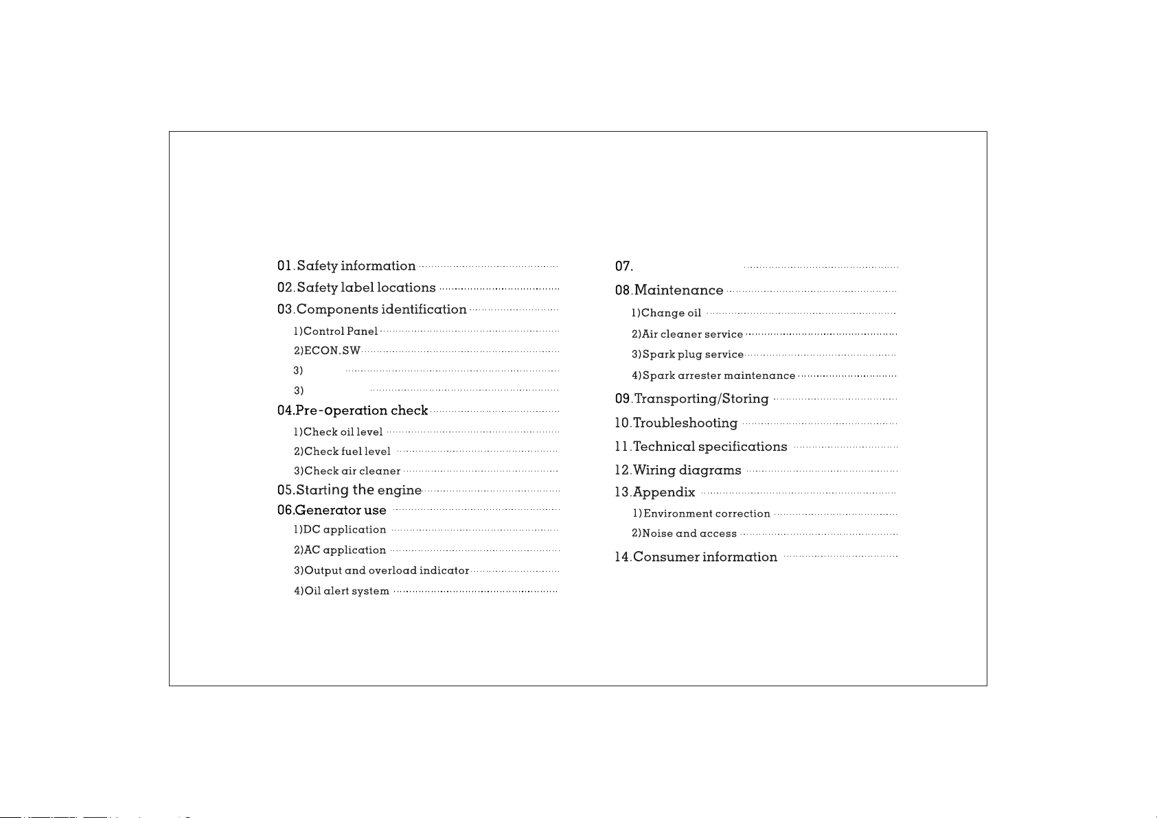
CONTENT
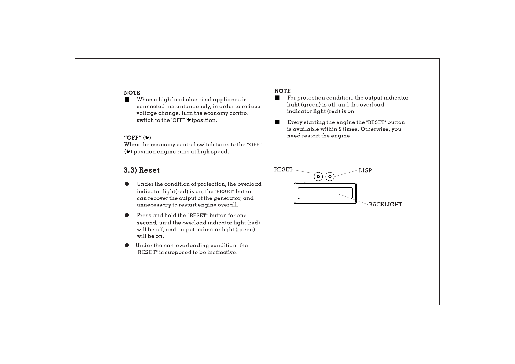
RESET
Hour-meter
04
06
07
08
08
09
09
10
10
11
12
13
15
16
18
19
19
Stop the engine
20
21
21
23
24
25
27
29
30
31
32
32
33
34
Page 6

1.SAFETY INFORMATION
To ensure personal and property safety, please
carefully read the following information.
WARNING
• Read and understand the user manual before
using the generator.
• The emission of engine contains poisonous
carbon monoxide. Use the generator in the
ventilated condition.
• Do not touch the hot muffler, when the generator
is running, or before cooling.
• Petrol is explosive and flammable in the
specified conditions when refueling, the
generator needs to be stopped and be kept
cigarette and fire source away.
• Do not connect to the building’s electrical system
or other generator, in order to avoid the electric
shocks and fires.
• The running generator must keep one meter
distance with constructions and other
electrical appliances at least.
• Place the generator on the leveled surface, in
order to avoid overturning or spilling fuel.
• Children and pets should be keep away the
operation area.
• Do not operate with wet hand.
• Do not expose the generator to rain, moisture
or snow.
• Place the generator at least 1 m away from
buildings or other equipments during
operation.
• The major repair work should be carried out
only by professionally trained person.
• Do not use the generator in underground
working
• Do not use the generator in potentially
explosive atmospheres
• Use personal protective equipment: glove,
mask, earplugs, when you operate or maintain
the generator
<<04>>
Page 7
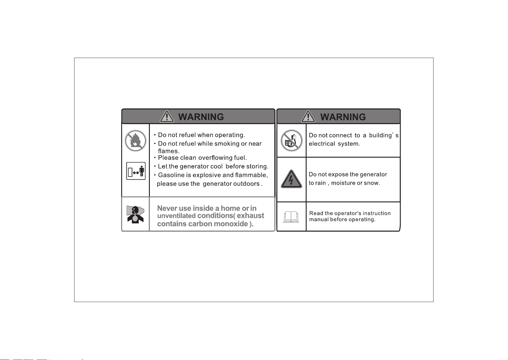
SAFETY LABEL:
<<05>>
Page 8
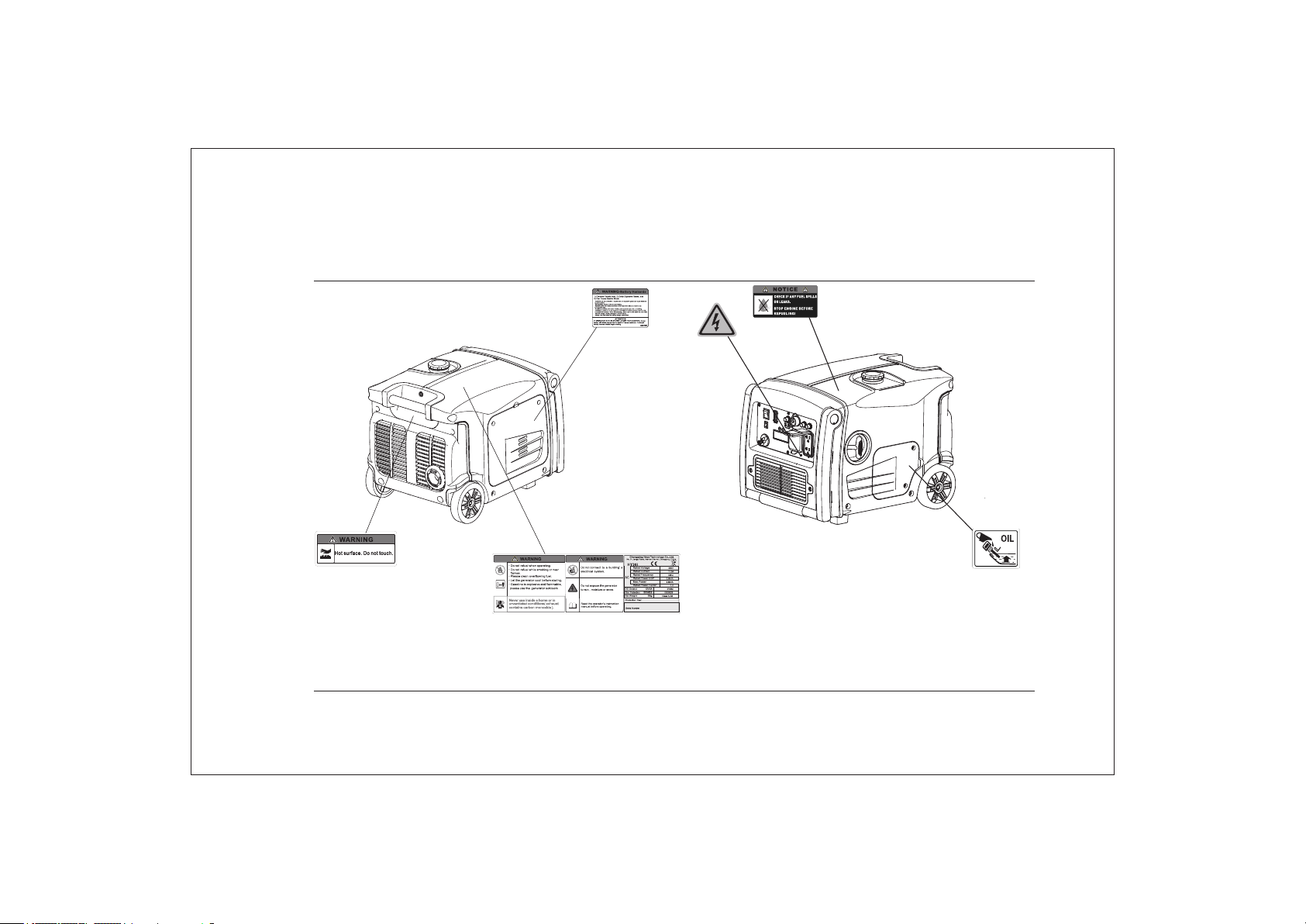
2. SAFETY LABEL LOCATIONS
<<06> >
Page 9
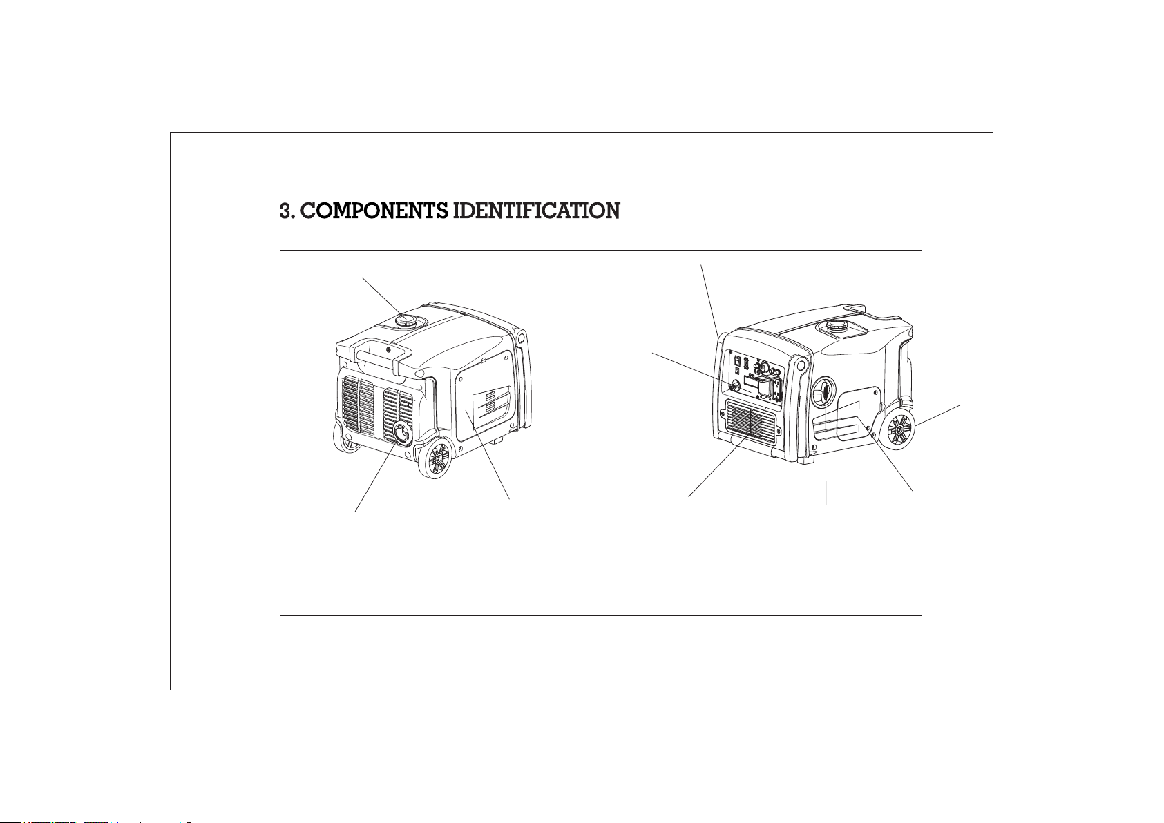
FUEL CAP
MUFFLER
AIR CLEANER
MAINTE NAN CE COVER
HANDLE
CONTROL
PANE L
BATTERY
MAINTE NAN CE COVER
STARTER GRIP
OIL
MAINTENANCE
COVER
<<07> >
WHEEL
Page 10
4
7
5
6
2
3
9
1
Hour meter
1
DC Terminal
2
DC Protector
3
Indicator Lights
4
5
E
CON. SW
6
Fuel Switch
7
Engine Switch
8
AC Receptacle
9
Ground Terminal
8
<<08> >
Page 11
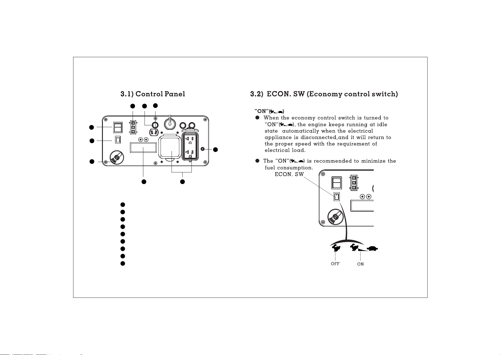
3. 4) Hour-meter
• Press the “DISP” button to display the voltage/
frequency of output, the engine speed and
cumulative working time.
• Press the “DISP” button, the back-light of hourmeter will be on, and it will be off without
operating the button for 10S.
<<09> >
Page 12
Oil Cap acity:0.6L
<<10> >
Page 13
NOTE
• Before the engine oil reduces below the safety
margin, low oil alert system will close the engine
automatically. The oil alert indicator light red will
be on.
• To avoid the inconvenience caused by
unexpected stopping,it is still advisable to check
the engine oil level regularly.
• Before the engine oil reduces below the safety
margin, low oil alert system will close the
engine automatically. The oil alert indicator
light (red) will be on.
• To avoid the inconvenience caused by
unexpected stopping, it is still advisable to
check the engine oil level regularly.
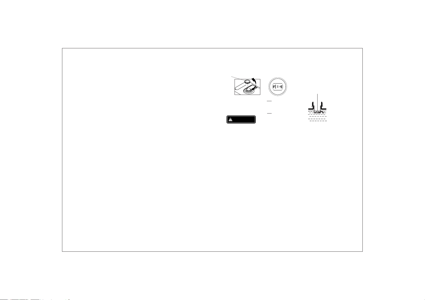
4.2) Check Fuel Level
Fuel recommend: use unleaded Petrol
(Research Octane Number of 91 or higher, Pump
Octane Number of 86 or higher)
Never use stale or contaminated Petrol or an oil/
Petrol mixture,
Avoid getting dirt or water into the fuel tank.
Do not use a mixture Petrol containing ethanol or
methanol; otherwise, it will seriously damage the
engine.
FUEL CAP
OPEN
WARNING
THE HIGHEST
F
FUEL LEVEL
THE LOWEST
E
FUEL LEVEL
UPPER LIMIT MARK
Fuel C apaci ty: 7.4 L
• Petrol is extremely explosive and flammable.
• Around the refueling area and fuel storage
area, prohibit smoking and firing.
• Do not overfill the fuel tank (no fuel above the
red upper limit mark). After refueling, make sure
the fuel cap is closed properly and securely.
• Do not make fuel spill from fuel tank. (No
residual fuel around the neck of tank, before
starting engine)
• Avoid contacting with skin or breathing the fuel
vapor.
• KEEP OUT OF REACH OF CHILDREN.
<<11> >
Page 14

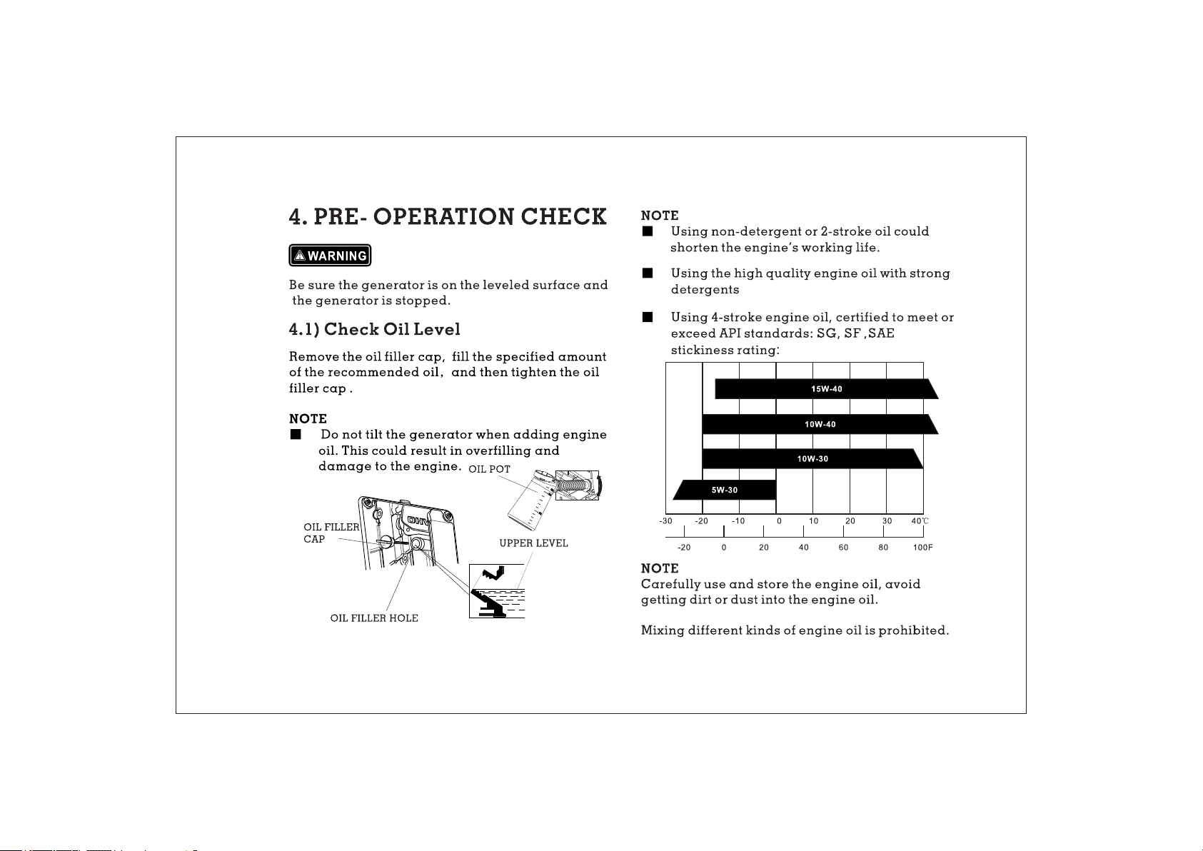
4.3) Check Air Cleaner
Check the air cleaner element to be sure it is clean
and in good condition.
a. Loosen the air cleaner maintenance cover
screws, and remove the cover.
COVER SCREW
AIR CLEANE R
MAI NTENA NCE
COVER
b. Loosen the air cleaner cover screws, and remove
the cover.
c. Check the element, clean or replace it, if
necessary.
NOTE
Do not run engine without the air
cleaner
element, the engine will be
damaged without the air filter being
fitted.
AIR CLEANER ELEMENT
AIR CLEANER
COVER
<<12> >
Page 15
5. STARTING THE ENGINE
■ For some models, the generator provides three
means to starting the engine: recoil starter, local
electrical starting, wireless remote electrical
starting.
NOTE
■ Before starting engine, disconnect load with
AC receptacle.
■ Fueling at the first time, refueling, or storing
for a long time, the Fuel Switch should firstly be
opened for ten or twenty seconds, in order that e
enough fuel enters into carburetor.
WAR NING
● Never use inside a home or the unventilated
condition.
5.1) Turn the fuel switch to the “ON” position.
ON
OFF
5.2) Turn the engine switch to “ RUN/REMOTE”
position.
STOP
RUN/REMOTE
START
<<13> >
Page 16

NOTE
When the engine switch turn to “RUN/REMOTE”
position, the engine will enter the stand-by
starting mode. Starting the engine within
15min, otherwise, the mode will be ineffective.
If the generator re-enters the stand-by starting
mode again, the engine switch should be return
to “STOP”, and then turn to “RUN/REMOTE”.
STARTER GRIP
5.3) Choose one of the starting modes to start the
engine.
CAUTION
The starting battery must be fitted and
sufficiently charged to start the generator, in all
starting modes.
a) Manual starting
Pull the starter grip slowly until it is engaged,
then pull it quickly.
NOTE
Return the starter grip slowly by hand. Do not
make the starter grip spring back quickly.
b) Local electrical starting
Turn the engine switch to “START” position,
and then let the engine switch return to
“RUN/REMOTE” position.
STOP
RUN/REMOTE
START
<<14> >
Page 17

NOTE
Engine switch should not stay “START” position more
than 1 seconds during starting.
c) Wireless remote electrical starting
Press “START” ( ) button of the controller once.
NOTE
• If the generator stops and can not restart,
check the oil level firstly.
• If the oil alert indicator light (red) is on during
the generator running, add oil.
NOTE
• The controller operate distance less than 8m
without any obstacles, or less than 3m with one
obstacle.
• The battery of controller can be used for 2
years. If the battery wares out, replace with a
new one.
Caution
Every generator delivers one controller with
the generator. If the controller is lost, contact
your dealer to purchase and decode a new
one.
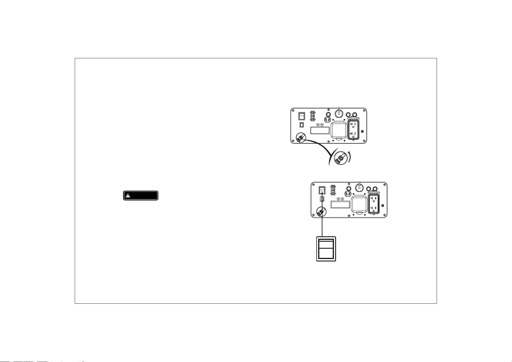
Carbure tor Modificat ion for High Alti tude
Operation
At high altitude, the standard carburetor air-fuel
mixture will be too rich. Performance will
decrease, and fuel consumption will increase. A
very rich mixture will also foul the spark plug and
cause hard starting.
If the generator operates at high altitude, change the
main nozzle or adjust the idling screw of carburetor
If the generator always operates at altitude above
<<15> >
Page 18

1 000 meters contact an authorized Cobra
servicing to modify the carburetor
Generator output power should be modified
according to the altitude and ambient
temperature The correction factor refers to
chapter 13.
WAR NING
If the carburetor has been modified for high
altitude operation, the air-fuel mixture will be
too lean for low altitude use. Operation at low
altitude may cause the engine to overheat
and result in serious engine damage. The
carburetor needs return to original
specifications.
6. GENERATOR USE
WAR NING
Be sure to ground the generator when the
connected electrical appliance is grounded.
Do not connect to the building’s electrical
system, in order to avoid the electric shocks
and fires.
EARTH
MARK
GROUND TERMINAL
Page 19

WARNING
6.1) DC Application
• For continuous operation, do not exceed the
rated out-put power of generator.
• Do not make parallel connection with other
generators.
• Do not connect an extension to the exhaust pipe.
• When an extension cable is required, be sure to
use a tough rubber sheathed flexible cable
(according to IEC245 or equivalent standards).
The maxmim length of the
2 extension cable: 60m for cable of 1.5mm ;
2
100m for cable of 2.5mm .
• Keep away from other electric cables or wires.
NOTE
• The DC receptacle can be used while the AC
power is in use. If both are used at the same
time, be sure not to exceed the total power for
AC and
• (AC:2.6kVA, DC:5A)
• Most of motor appliances require more than
their rated wattage, when starting.
The DC receptacle, 15-30V under no load condition,
may be used for charging 12V battery only.
NOTE
In DC operation, turn the ECON SW to the
“OFF” ( ) position.
6.1.1) Disconnect the vehicle battery ground cable
from the negative battery terminals.
6.1.2) Connect the DC terminals to battery
terminals with the charging cable
CAUTION
Connect red lead to positive battery terminal and
black lead to negative battery terminal.
6.1.3) Turn ECON SW to “OFF” ( ) position and
then start engine
<<16> >
Page 20

CHARGING CABLE
NOTE
Do not start the automobile engine when the
generator is still connected to the battery,
otherwise the generator will be damaged.
Disconnecting the charging cable
WAR NING
The battery can release the explosive gases.
Keep the battery away from spark/fire. Charge
the battery in a ventilated condition.
Battery electrolyte contains sulfuric acid that will
cause severe burn of skin and eyes. Therefore it
is necessary to wear the protective clothing and
mask.
If battery electrolyte gets into eyes flush
thoroughly with
warm water for 15min at least
and call a doctor immediately
If you swallow a little of b
accidentally
flush thoroughly with water
attery electrolyte
your mouth and then drink large quantities
of water or milk
oil
and call a doctor immediately
with magnesia or vegetable
1) Stop the engine.
2) Disconnect the black lead from the negative
battery terminal.
3) Disconnect the red lead from the positive
battery terminal.
KEEP OUT REACH OF CHILDREN
<<17> >
Page 21

NOTE
• While using the AC power, you can use the DC
power at the same time.
• Overload indicator light is on, disconnect
load, press “RESET” button to recover the
output of generator.
OVERLOAD INDICATOR
LIGHT(RED)
6.2) AC applications
6.2.1) Start engine and make sure the output
indicator light (green) is on.
6.2.2) Confirm all electrical appliances are switched
off, and connect the appliance plugs to the
generator receptacle.
NOTE
To obtain the best working and longest working life of
the generator, a new generator is supposed to run for
20 hours at 50% rated load.
PLUG
NOTE
Confirm all electrical appliances are in good working
condition before connecting them to the generator. If
an electrical appliance becomes abnormal, sluggish,
or stops suddenly, shut off the generator engine
immediately, and disconnect the appliance.
<<18> >
Page 22

6.3) Output and Overload Ind
icator
6.4) Oil alert system
In normal operating, output indicator light
(green) will remain on.
If the generator is overload (over 2.6kVA), or the
connected appliance has short-circuited, the output
indicator light (green) is off, and overload
indicator light (red) is on. The AC power will be
switched off, but engine is still running.
If the overload indicator light (red) is on,
disconnect the electrical appliances firstly, then
stop the engine, and start it again. If the overload
indicator light (red) is off and the output
indicator light (green) is on, reconnect the
electrical appliances. Otherwise stop the engine
and check the generator.
OVERLOAD INDICATOR
LIGHT(RED)
OUTPUT INDICATOR
LIGHT (GREEN)
The oil alert system is designed to prevent engine
damage caused by an insufficient amount of oil
in the crankcase. Before the oil level in the
crankcase falls below a safe limit, the oil alert
system will automatically shut down the engine
(the engine switch remains in the
“RUN/REMOTE“position).
If the oil alert system shuts down the engine, the
oil alert indicator light (red) will be on. Check
the engine oil level.
OIL ALERT IND ICATOR
LIGHT ( RED)
<<19> >
Page 23

7. STOPPING THE ENGINE
To stop the engine in an emergency, turn the
engine switch to the
7. 1) Switch off the connected electrical appliances,
and remove their plugs.
PLUG
7.2) Turn the engine switch to the “STOP” position,
or press the “STOP” ( ) button of the
controller.
NOTE
■ The controller operate distance less than 8m
without any obstacles, or less than 3m with
one obstacle.
“STOP ” position immediately.
STOP
RUN/REMOTE
START
7.3) Turn the fuel switch to the “OFF” position.
ON
OFF
<<20> >
Page 24

MAINTENANCE
8.
The purpose of the maintenance and adjustment
schedule is to keep the generator in the best
operating condition.
Spa rk plug
Spark arrester
Valve Clearance
Combustion Chamber
Fuel tank& filter
Fuel l ine
Rep lace
Check-adjust
Cle an
Cle an
Che ck
⊙
+(2)
Aft er ever y 300 hrs(2)
Eve ry year(2)
Eve ry 2 years ( Rep lace if n ecess ary)(2)
WARNING
Stop the engine before performing any
maintenance. If the engine must run, be sure the
area is well ventilated. The exhaust contains
poisonous carbon monoxide gas.
Use genuine Cobra or equivalent quality
components to replace the wear components.
Maintenance Schedule
Reg ular Se rvice
Period (3 )
Ite m
Eng ine
oil
Air
cle aner
Spa rk plug
Check level
Cha nge
Che ck
Cle an
Check-adjust
Eac h
use
First
mon th
or
10 hr s.
Eve ry 3
mon ths
or
50 hr s.
+(1)
Eve ry 6
mon ths
or
100 h rs.
Eve ry
2 yea rs
or
300 h rs.
NOTE
(1) Service more frequently when used in dusty areas.
(2) These items should be serviced by your servicing
dealer, unless you have the proper tools and are
mechanically proficient. Refer to Cobra manual for
service procedures.
(3) For commercial use, long hours of operation to
determine proper maintenance intervals.
8.1) Change Oil
Drain the oil rapidly and completely while the
engine is still warm.
8.1.1) Loosen screws of the oil maintenance
cover, and remove the cover.
8.1.2)Remove the oil dipstick and the bottom
rubber.
<<21> >
Page 25

8.1.3)Place oil collection pan under oil drain plug.
8.1.4)Remove the oil drain plug, and drain oil into
the oil collection pan completely.
8.1.5) Reinstall the oil drain plug.
OIL RULER
BOLT
COVER SCREW
AIR CLEANE R
MAI NTENA NCE COVER
OIL F ILLER
CAP
OIL P OT
UPP ER LEVE L
Oil Cap acity: 0.6L
OIL F ILLER H OLE
8.1.6)Refill the recommended oil, and check the
oil level.
8.1.7)Reinstall the oil dipstick and tight it.
After oil change, wash your hands with soap.
<<22> >
Page 26

NOTE
For conforming to the environment requirement, the
used oil will be put into a sealed container and then
be transported to the service station for recycler. Do
not throw it into the trash or pour it on the ground.
8.2) Air Cleaner Service
A dirty air cleaner will restrict air flow into the
carburetor.Clean and maintain the air cleaner
regularly, especially in the extremely dusty areas.
WAR NING
Do not use Petrol or low ignition point solvents for
cleaning. They are flammable and explosive under
certain conditions.
NOTE
Never run the generator without air
cleaner,damage to the engine result.
8.2.1) Loosen three screws of the air cleaner
maintenance cover, and remove the cover.
COVER SCREW
AIR CLEANE R
MAI NTENA NCE COVER
8.2.2) Loosen the air cleaner cover screws and
remove the cover.
AIR CLEANER
ELEMENT
AIR CLEANER
COVER
<<23> >
Page 27

8.2.3) Take out the air cleaner element, and clean
it with non- flammable or high flash point
solvent, then dry it.
8.2.4) Soak the air cleaner element in the clean
engine oil, and squeeze out the redundant
oil.
ELE MENT
8.2.5) Reinstall the air cleaner element and cover.
8.2.6) Reinstall the maintenance cover, and tighten
the screws.
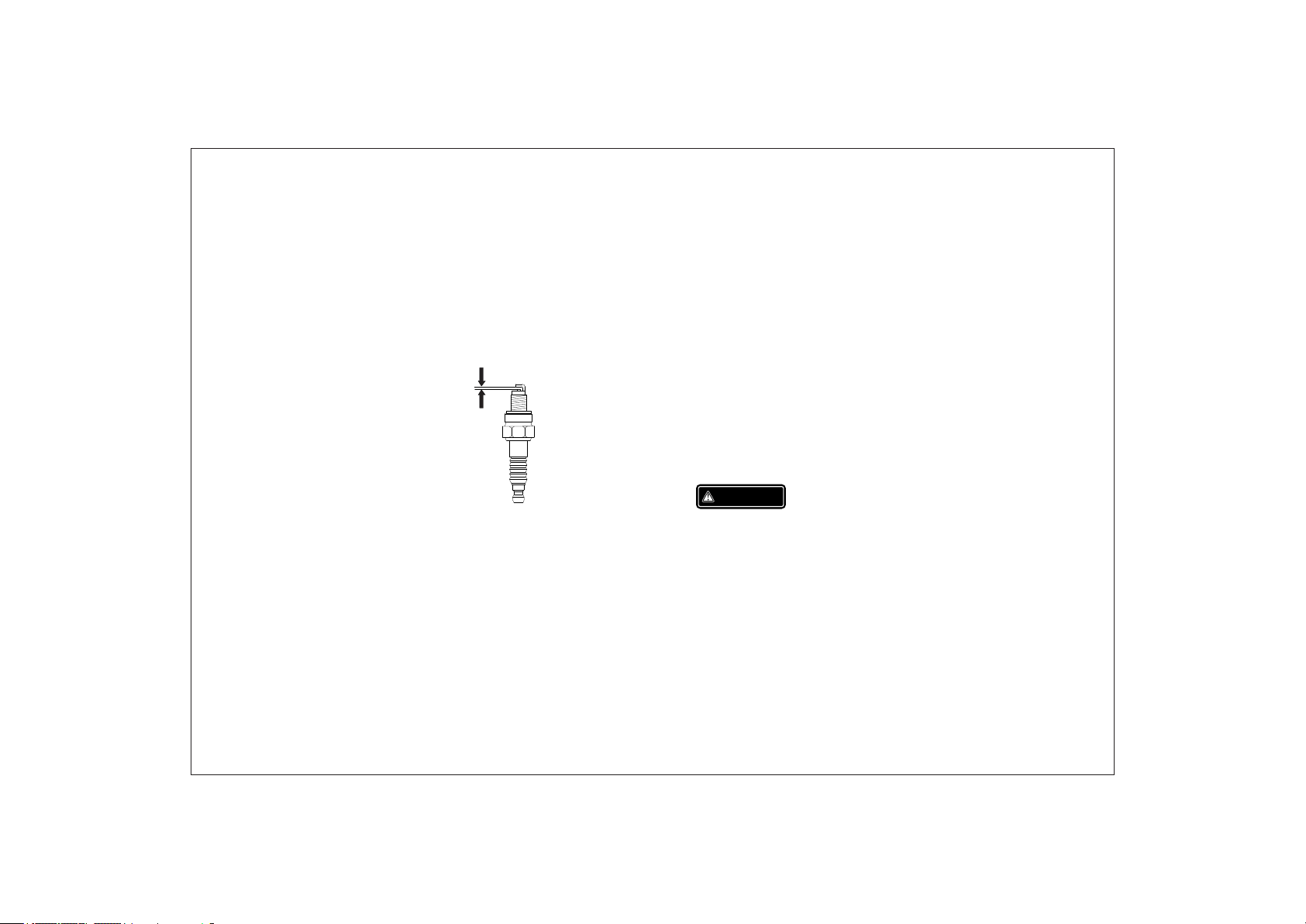
8.3) Spark Plug Service
Recommendation spark plug: NGK BPR7ES or
Torch F7TC
Check the spark plug gap and clean the carbon
deposition at the bottom of the spark plug.
8.3.1) Remove the spark plug cap.
<<24> >
Page 28
8.3.2) Take off the spark plug with the spark plug
spanner.
8.3.3) Visual inspection the spark plug. Fit a
new one if its insulator is cracked or chipped.
Clean it with a wire brush if the spark plug is
reused.
0. 60- 0.7 0 mm
(0.024-0.028in)
8.3.4) Measure the spark plug gap with a feeler
gauge. The normal value:0.6-0.7mm(0.024-
0.028in). Adjust the gap by bend one of the
electrode carefully.
8.3.5) Reinstall the spark plug carefully, by hand,
to avoid cross-threading. A new spark plug
should be tightened 1/2 turn with a spanner.
A used Spark plug should be tightened 1/8 to
1/4 turn with spanner.
8.3.6) Reinstall the spark plug cap
8.3.7) Reinstall the spark plug maintenance cover.
NOTE
• The spark plug must be securely tightened.
Tightening in wrong way will cause the spark
plug to be too hot and damage the engine.
• Never use a spark plug with an improper heat
range.
8.4) Spark Arrester Maintenance
WARNING
The spark arrester must be maintained every
100h service.
8.4.1)Remove the screws, and remove the
muffler guard.
<<25> >
Page 29

8.4.2)Take off the spark arrester from the
muffler after the engine cool down.
8.4.3)Use a brush to remove carbon deposits from
the spark arrester. If the spark arrester is
worn, replace it.
8.4.4)Reinstall the spark arrester and muffler
guard.
8.5 Replace battery and fuse
For some models, fitted with electrical starting
system and starting battery. If the battery does
not function, replace from your dealer.
Battery speci fications
Voltage Capacity Dimension
L≤138mm
12V 7Ah W≤66mm
H≤88mm
<<26> >
Page 30

NOTE
■ When the engine is running, the battery will be
charge by the charging system of generator.
■ The battery will remain charged in storage for a
long period. For using other charging system, the
charging current should be less than 0.15
amperes (c: battery rated capacity) .
Replace t he battery procedure
8.5.1) Loosen the screws of the battery
maintenance cover, remove the cover.
8.5.2) Unhook the battery belt.
8.5.3) Remove the black cable from battery
negative(-) terminal, and then remove the red
cable from battery positive(+) terminal.
8.5.4) Remove the battery from battery tray, and
replace a new one.
8.5.5) Reconnect red cable to battery positive(+)
terminal, and reconnect black cable to
battery negative(+) terminal.
8.5.6) Hook the battery belt, and reinstall the
cover.
Page 31

9.TRANSPORTING/STORING
Storing for a long period:
Avoid fuel spilling during transporting or temporary
storing, the engine switch should turn to “OFF’ position,
and the generator should place in normal operating
position. It is recommended not transport with fuel.
WAR NING
Tran sporting Gene rator:
Do not overfill the fuel tank. (No residual fuel
on the neck of tank)
Do not use the generator on the transport
vehicle. The generator should be used under
a good ventilated condition.
Avoid exposing directly in the sunshine. Avoid
leaving in a vehicle during high temperatures.
The high temperature inside the vehicle could
cause fuel to vapourise resulting in a possible
explosion.
It is recommended to drain off the fuel, when the
generator is transported.
9.1) Make sure the storage area without
excessive humidity and
9.2) Drain off the fuel.
WAR NING
Keep away from smoking, flames and spark,
Petrol is explosive and flammable in the
specified condition.
a. Drain off the Petrol in the fuel tank, storing
into a suitable container.
dust.
<<27> >
Page 32

b Turn the fuel switch to “ON” position, and loosen
the carburetor drain screw to discharge
Petrol inside of carburetor.
c. Take off the spark plug cap, pull the starter grip
three or four times, discharge the Petrol from the
fuel lines.
d. Turn the fuel switch to “OFF” position, and tighten
the drain screw of carburetor.
e. Reinstall the spark plug cap.
STARTER GRIP
9.3) Change new oil while engine is still warm
from operation.
9.4) Remove the spark plug, and pour a
tablespoon of clean engine oil(10~20ml) into
the cylinder. Revolve the engine several
times to distribute the oil,and reinstall the
spark plug.
9.5) Pull the starter grip slowly until you feel
resistance. At this point, the piston is coming
up on its compression stroke and both the
intake and exhaust valves are closed. In this
position, it helps to protect the engine from
internal corrosion.
<<28> >
Page 33

10.TROUBLESHOOTING
Appliance does not operate:
When the engine can not be started:
Is there fuel in the tank?
YES
Is the fuel switch on?
YES
Is the engine switch in” RUN/REMOTE” ?
YES
Is stand-by starting mode exceed 15min?
YES
Is there enough oil in the en gine?
YES
Is the spark plug in good con dition?
YES
If the engine still does no t
start, contact with an
authorized Cobra
dealer
Refill the fuel tank
NO
Turn the fuel switch on
NO
Turn th e engin e switc h to
“RU N/REM OTE”
NO
Reset the engine switch(Turn to
STOP, then to RUN/REMOTE)
NO
Add the recommended oil
NO
Clean, readjust gap
and dry the spark p lug.
NO
Replace it if necessary
Is the output indicator
light ON?
Is the overload indicator
YES
light ON?
YES
Check the electrical
appliance for any fault.
YES
NO
NO
NO
Contact with an
authorized Cobra
dealer
Contact with an
authorized Cobra
dealer
Stop engine and then replace or repair the appliance
Restart the engine
DC receptacle without any electricity:
Check the electrical appliance
for any fault
NO
Is the DC circuit
protector OFF?
Change or replace the appliance
YES
YES
Pus h the DC circuit
protector ON.
NO
Contact with an
authorized
Cobra
dealer
<<29> >
Page 34

11. TECHNICAL SPECIFICATIONS
Specifications
Model
Type
Engine Displacement
Bore*Stroke
ENGINE
Compression Ratio
Rated power
Ignition System
Start System
Fuel Type
Oil Capacity
Oil Model
Model
GENERATOR
Rated Frequency
Rat ed Voltage
Rat ed Current
Rated Speed
Rated Output Power
Max. Output Power
Parameters
DJ170F
4-stroke, overhead valve,
single cylinder, fo rced-air cooling
208ml
70.0mm*54.0mm
8.5:1
4.0kW/3600min
Full t ransistor
Rec oil sta rter& E lectr ical st artin g&
Wireles s remot e start ing
Petrol without lead
0.6L
SE 15W-30
30i
HY
50Hz
230V
12.17A
3600min
2
.6kVA
.8kVA
2
-1
-1
OTHER SPECIFICATIONS
Fuel Tank Volume
Continuous Running Time
Fuel Consumption
Working Ambient Temperature
Max. Altitude
﹡Noise L
﹡﹡ Noise L
Dimensions (L*W*H )
Net Weight
wA
pA
12V/5ADC Output
7.4L
7.0h
490g/kW.h
-20 ~ 40
1000m
90dB/4m
54~59dB/7m
580mm* 508mm *450mm
35kg
Noise level is measured when the ECON.SW is
turned to ‘’ ON‘’( )
﹡: L shows the guaranteed sound power
wA
tested by 2000/14/EC.
﹡﹡: The noise level in “dB/7m” is the
arithmetic mean value of sound press level (L ) in
pA
four directions measured 7 meters away from the
generator.
The noise level may vary in different environments.
<<30> >
Page 35

12
WIRING DIAGRAMS
Hou rmete r
Aux.
.
Main
Winding
Winding 1
Engine Switch
INVERTER
Stepper Motor
ECON.SW
AC
Receptacl e
Ground
Terminal
Mod ule
Ign ition
Aux.
Winding 2
Act uator
Boo ster
Pla te
DC
Connector
Bat tery
12V 7 Ah
Ignition
Winding
Trigger
Winding
Oil sensor
Spa rk
plu g
Ignition
<<31> >
Page 36

13. APPENDIX
13.1) Environment Correction
The standard condition of rated power output:
Altitude:0m
Ambient temperature:25 C
Relative humidity:30%
Factor of environment correction:
Altitude(m)
0
500
1000
2000
3000
4000
25 30 35 40
1
0.93
0.87 0.85 0.82 0.80 0.78
0.75 0.73
0.64 0.62 0.60 0.58 0.56
0.54 0.52 0.50 0.48 0.46
o
Ambient temperature℃
0.98 0.96 0.93 0.90
0.91
0.89 0.87 0.84
0.71
0.69 0.66
NOTE: Relative humidity 60% correction factorC-
0.01;
Relative humidity 80% correction
factorC -0.02;
Relative humidity 90% correction factorC-
0.03;
Relative humidity 100% correctionfactorC-
0.04;
Example:
Rated power(P )2.6kVA generator(Altitude:
N
1000m) Ambient temperature: 35℃ ,Relative
45
humidity: 80%
P=Pn*(C-0.02)= 2.6*( 0. 82-0. 02)=2.08kVA
<<32> >
Page 37

13.2) Noise and Access
Noise emission measure according to ISO 8528-10,
EN ISO 3744, European Directive 2000/14/EC with
amendment 2005/88/EC
Model of generator set: HY30i
Sound Pressure Level: dB(A)68
Guaranteed Sound Power Leve 90dB(A) l:
Measurement Uncertainty K: 1. dB(A) 7
The quoted figures are emission levels and are not
necessarily safe working levels. Whilst there is a
correlation between the emission and exposure
levels, this cannot be used reliably to determine
whether or not further precautions are required.
Factors that influence the actual level of exposure
of work-force include the characteristics of the
work room, the other sources of noise, etc, i.e. the
number of machines and other adjacent
processes, and the length of time for which an
operator is exposed to the noise. Also the
permissible exposure level can vary from county.
This information, however, will enable the user of
the machine to make a better evaluation of the
hazard and risk.
<<33>>
Page 38

14. CONSUMER INFORMATION
Consumer Service Information
Please contact your retailer for any service related issues in the first instance.
As appropriate you may be referred to another Cobra dealer who is professionally trained to complete service
work as necessary. The Cobra dealer list is available at cobragarden.co.uk or contact 0115 986 2161 for
assistance.
When contacting your dealer, please have the following information to hand:
Model and serial number
Date of purchase
Detailed description of the problems
Dealer contact information and your: name, address, and telephone number
<<34> >
Page 39

EC DECLARATION OF CONFORMITY
We herewith declare, Cobra Garden Machinery
Henton & Chattell Ltd, London Road, Nottingham NG2 3HW United Kingdom
that the following machine complies with the appropriate basic safety and health requirements of the EC
Directive based on its design and type, as brought into circulation by us.
In case of alteration of the machine, not agreed upon by us, this declaration will lose its validity
Machine Description: Inverter Generator
Machine Type: IG32ESI (HY3200i)
Engine Displacement: 208 cm
3
Rated Output Power 2.6 kVA Max 2.8 kVA
Measured sound power level 68 dB(A)
Guaranteed sound power
level:
Applicable EC Directives: 2006/42/EC
2006/95/EC
2004/108/EC
2000/14/EC amended 2005/88/EC
Applicable Harmonized
Standards:
EN 12601:2010
EN 61000-6-2:2005
EN 61000-6-4:2007
Authorized Signature/Date/
Place:
Peter J. Chaloner 10/1/2019
96 dB(A)
Notified Body for EC Directive 2000/14/EC:0499
TÜV Rheinland LGA Products GmbH
Tillystrasse 2, 90431 Nürnberg, Germany 0197
Title of Signatory: Managing Director
Name and address of the
person authorized to
compile the technical file
Cobra Garden Machinery
Henton & Chattell Ltd, London Road, Nottingham NG2 3HW United Kingdom
Page 40

Cobra Garden Machinery
Henton and Chattell Ltd, London Road, Nottingham
NG2 3HW UK
 Loading...