

Page 1

INVERTER GENERATOR
USER MANUAL
Model:IG20SI
4-Stroke Engine
Page 2

Thank you for purchasing a Cobra Inverter Generator
● Cobra reserves the right of modification of product and revision of the manual without any notice.
● Take this manual as a part of the generator. If the generator is resold, it is required to take the manual along
with the generator.
● This manual contains how to correctly operate the generator, please read carefully before using the generator.
Correct and safe operation will guarantee your safety and extend the working life of generator.
● Cobra will continuously innovate and develop its products both in design and quality. The content of this
manual may have minor difference from the updated product. Please contact your supplier for further support.
IMPORTANT SAFETY NOTICE:
The emission of engines contains poisonous carbon monoxide. Use the generator
only outdoors and away from people.
NEVER use petrol powered equipment in a home, garage, tent, camper-van,
caravan, motor-home or boat. Even if doors, windows or vents are open. Only use
outdoors, well away from doors, widows and openings. Prevent inhaling exhaust
fumes.
Page 3

CONTENT
Hourm eter
04
06
07
08
08
09
10
10
11
12
13
15
17
18
19
20
20
22
22
23
25
26
28
30
31
32
33
33
34
36
Page 4

1.SAFETY INFORMATION
To ensure personal and property safety, please
carefully read the following information.
WARNING
distance with constructions and other
electrical appliances at least.
• Place the generator on the leveled surface, in
order to avoid overturning or spilling fuel.
• Children and pets should be keep away the
operation area.
• Do not operate with wet hand.
• Read and understand the user manual before
using the generator.
• The emission of engine contains poisonous
carbon monoxide. Use the generator in the
ventilated condition.
• Do not touch the hot muffler, when the generator
is running, or before cooling.
• Petrol is explosive and flammable in the
specified conditions when refueling, the
generator needs to be stopped and be kept
cigarette and fire source away.
• Do not connect to the building’s electrical system
or other generator, in order to avoid the electric
shocks and fires.
• The running generator must keep one meter
• Do not expose the generator to rain, moisture
or snow.
• Place the generator at least 1 m away from
buildings or other equipments during
operation.
• The major repair work should be carried out
only by professionally trained person.
• Do not use the generator in underground
working
• Do not use the generator in potentially
explosive atmospheres
• Use personal protective equipment: glove,
mask, earplugs, when you operate or maintain
the generator
<<04>>
Page 5
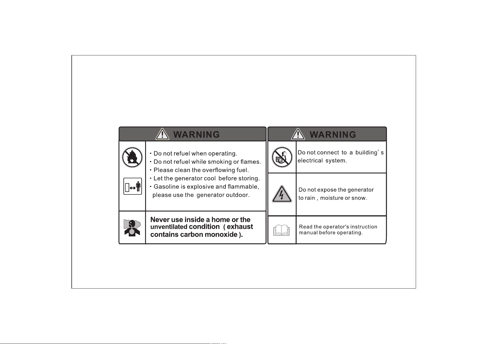
SAFETY LABEL:
<<05>>
Page 6
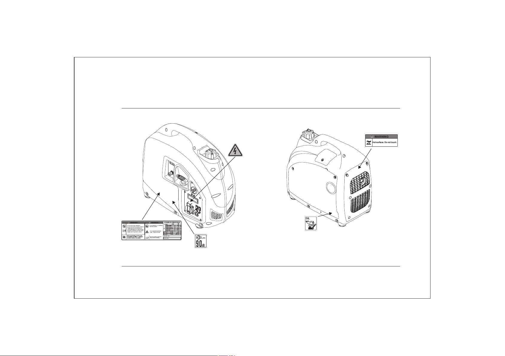
2. SAFETY LABLE LOCATIONS
<<06>>
Page 7
3. C IDENTIFICATIONOMPONENTS
CHOKE
KNOB
STARTER GRI P
FUEL SWIT CH
FUEL CAP
VENT LEVE R
FUEL C AP
CONTROL
PANE L
SPAR K P LUG
MAINTENA NCE
COV ER
AIR CLE ANE R
MAINTENA NCE COVER
MUFFLER
ECON. SW
ENGINE SWI TCH
<<07>>
Page 8
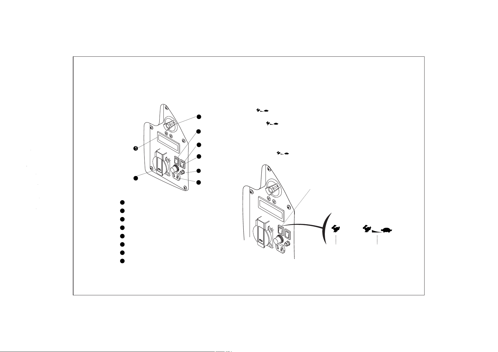
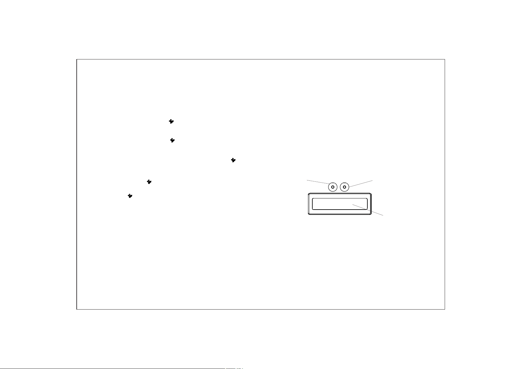
3.1) Control Panel
2
1
Hourmeter
AC Receptacle
2
3
Ground Terminal
4
DC Receptac le
5
DC Circuit Protector
Engine Swit ch
6
7
ECON. SW
8
Fuel Switc h
3.2) ECON. SW (Economy control switch):
“ON”( )
8
7
6
5
3
4
• When the economy control switch is turned to
“ON”( )
,the engine keeps running at idle state
automatically when the electrical appliance is
disconnected,and it will return to the proper speed
with the requirement of electrical load.
● The “ON”( ) is recommen ded to minimize the fuel
ECON. SW
ONOFF
<<08>>
Page 9
NOTE
• When a high load electrical appliance is
connected instantaneously, in order to reduce
voltage change, turn the economy control switch
to the“OFF”( )position.
• In
DC operation, turn the economy control switch
to the “OFF”( )position.
• Connect both AC load and DC load, turn the
economy control switch to the “OFF”( ) position.
will be off, and output indicator light (green)
will be on.
• Under the non-overloading condition, the
"RESET" is supposed to be ineffective.
• Press DISP; then lighten the backlight.
• Display voltage/frequency, engine speed,
cumulative working time in turn.
NOTE
• No button in 10S, the backlight shut off.
“OFF” ( )
When the econ omy control switch turns to th e “OFF”
( ) position en gine runs at high s peed.
3.3) Hourmeter
• Under the condition of protection, the overload
indicator
recover the output of the generator, and
unnecessary to restart engine overall.
• Press and hold the “RESET” button for one second,
until the overload indicator light (red)
light(red) is on, the "RESET" button can
RESET
NOTE
• For protection condition, the output indicator
light (green) is off, and the overload indicator
light (red) is on.
• Every starting the engine the "RESET" button is
available within 5 times. Otherwise, you need
restart the engine.
DISP
backlight
<<09>>
Page 10
4. PRE- OPERATION CHECK
WARNING
Be sure the gen erator is on the le veled surfa ce and
the generat or is stopped.
4.1) Check Oil Level
NOTE
• Using non-detergent or 2-stroke oil could
shorten the engine’s working life.
• Using the high quality engine oil with strong
detergents
• Using 4-stroke engine oil, certified to meet or
exceed API standards: SG, SF ,SAE stickiness
rating:
Remove the oil filler cap, fill the specified amount of
t
he recommended oil and then tighten the oil filler
cap .
NOTE
• Do not tilt the generator when adding engine
oil. This could result in overfilling and
damage to the engine.
OIL FILLER
CAP
UPPER LEVE L
OIL FILLER H OLE
OIL POT
Oil Cap acity:0.41L
15W -40
10W -40
10W -30
5W- 30
-30 -20 -10 0 10 20 3 0
-20
20 40 60 8 0
0
40℃
100 F
NOTE
Carefully u se and store the en gine oil, avo id
getting dir t or dust into the en gine oil.
Mixing diff erent kinds of engine oil is pro hibited.
<<10>>
Page 11
NOTE
• Before the engine oil reduces below the safety
margin, low oil alert system will close the engine
automatically. The oil alert
indicator light red
will be on.
• To avoid the inconvenience caused by
unexpected stopping,
it is still advisable to
check the engine oil level regularly.
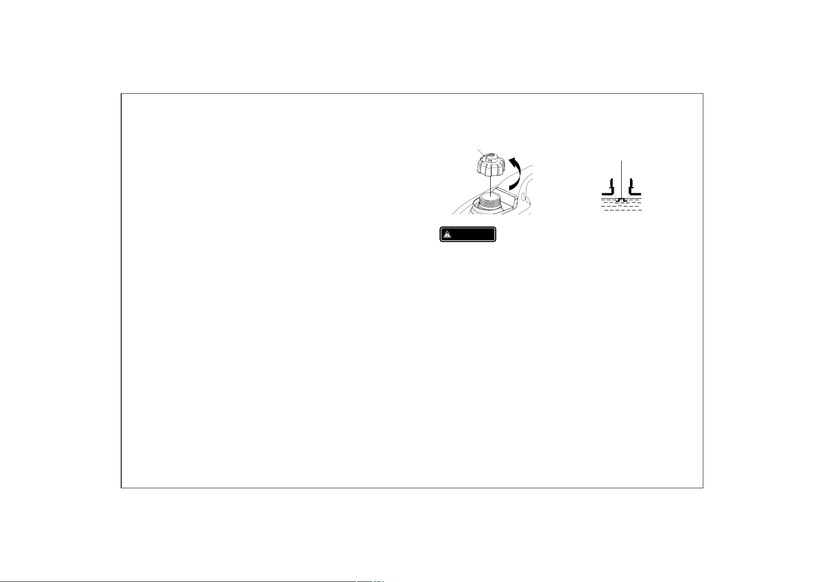
FUEL CAP
WARNING
OPEN
UPPER LIMI T MAR K
Fuel C apaci ty: 3.6 L
4.2) Check Fuel Level
Fuel recommend: use unleaded Petrol
(Research O ctane Number of 9 1 or higher, Pump
Octane Number of 86 or higher)
Never use stale or contaminated Petrol or an oil/
Petrol mixture,
Avoid getting dirt or water into the fuel tank.
Do not use a mixture Petrol containing ethanol or
methanol; otherwise, it will seriously damage the
engine.
• Petrol is extremely explosive and flammable.
• Around the refueling area and fuel storage
area, prohibit smoking and firing.
• Do not overfill the fuel tank (no fuel above the
red upper limit mark). After refueling, make sure
the fuel cap is closed properly and securely.
• Do not make fuel spill from fuel tank. (No
residual fuel around the neck of tank, before
starting engine)
• Avoid contacting with skin or breathing the fuel
vapor.
• KEEP OUT OF REACH OF CHILDREN.
<<11>>
Page 12
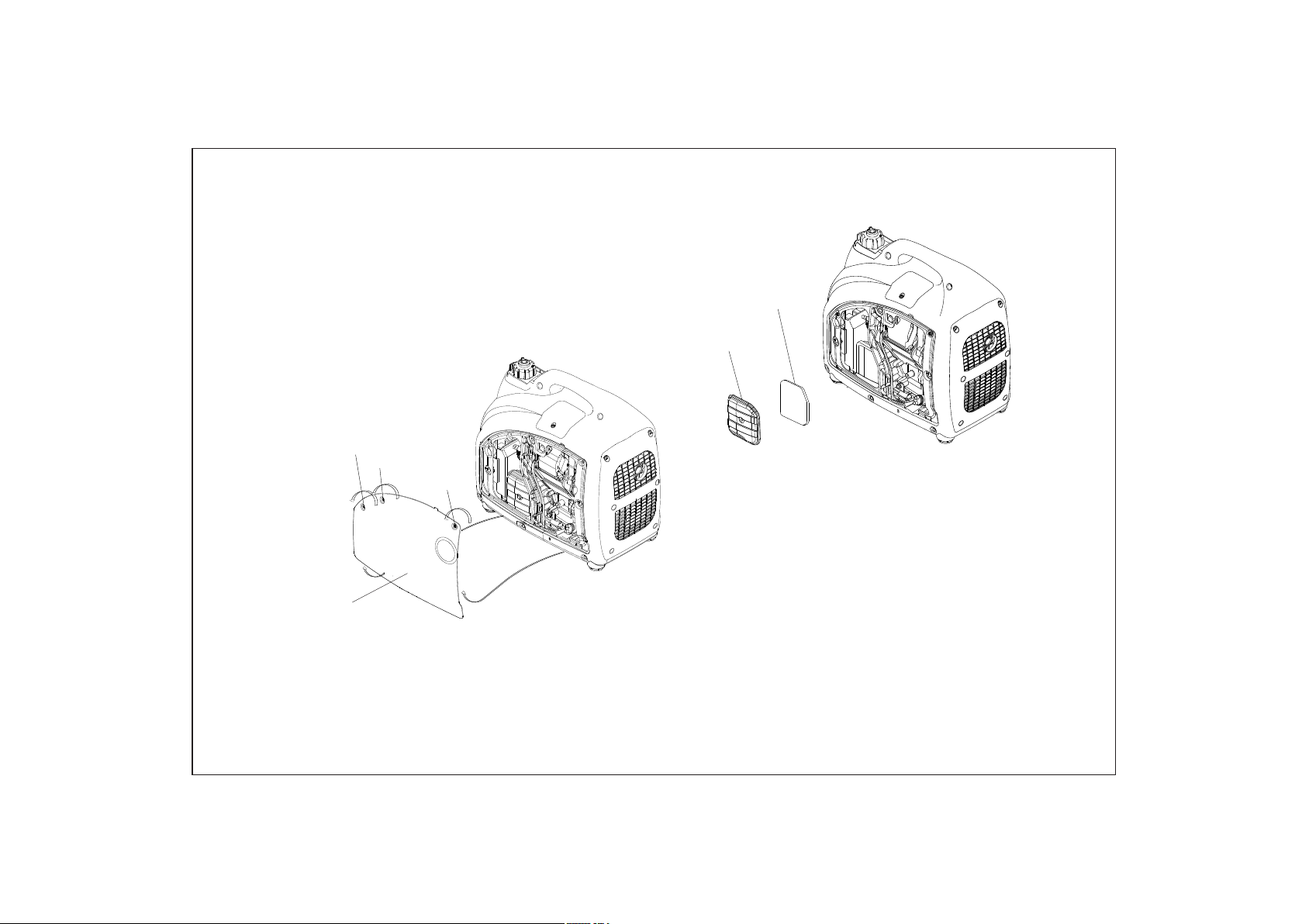
4.3) Check Air Cleaner
Check the air c leaner element to be sure it is cl ean
and in good con dition.
a.Loosen th ree screws of the a ir cleaner
maintenan ce cover, and re move the cove r.
COVER SCREW
COVER SCREW
COVER SCREW
AIR CL EANE R
MAI NTENA NCE COVER
b. Loosen the ai r cleaner cover s crew, and re move
the cover
AIR CLEANER ELEMENT
AIR CLEANER
COVER
c. Check the element, clean or replace it,if necessary.
NOTE
Do not run engine without the air cleaner element.
Operating the generator without the filter will damage
the engine.
<<12>>
Page 13

5. STARTING THE ENGINE
NOTE
Before starting engine, disconnect load with AC
receptacle.
5.1) Turn the fuel ca p vent lever to t he “ ON”
sition.
po
FUEL CAP VEN T LEV ER
OFF
NOTE
When transporting generator, turn the fuel cap vent
lever to the “OFF”
position.
5.2) Turn fuel switch to the “ON ” position.
FUEL SWITC H
ON
5.3) Turn the
ON
ON
engine swit ch to “ON” position.
<<13>>
Page 14

5.4) Pull t he choke knob f ully
CHOKE KNOB
out.
STARTER G RIP
NOTE
Do not pull out the choke knob, when engine is hot or
ambient temperature is high.
5.5) Pull t he starter gr ip slowly
until it is eng aged,
then pull it qu ickly.
NOTE
Return the starter grip slowly by hand. Do not make
the starter grip spring back quickly.
5.6) Push t he choke knob t o the original po sition,
when the engi ne warms up.
<<14>>
Page 15

CHOKE KNOB
NOTE
If the generator stops and can not restart, check
the oil level firstly.
Carbure tor Modificat ion for High Alti tude
Operation
At high altitude, the st andard carburetor air-fuel
mixture wil l be too rich. Perform ance will
decrease, a nd fuel consump tion will inc rease. A
very rich mixture will also foul t he spark plug and
cause hard st arting.
If the generator operates at high altitude, change the
main nozzle or adjust the idling screw of carburetor
If the generator always operates at altitude above
1000 meters contact an authorized Cobra service
dealer to modify the carburetor.
Generator output power should be modified
according to the altitude and ambient temperature.
The correction factor refers to 13.2
WARNING
If the carburetor has been modified for high altitude
operation, the air-fuel mixture will be too lean for low
altitude use. Operation at low altitude may cause the
engine to overheat and result in serious engine
damage. The carburetor needs return to original
specifications.
<<15>>
Page 16

6. GENERATOR USE
WARNING
• Be sure to ground the generator when the
connected electrical appliance is grounded.
• Do not connect to the building’s electrical
system, in order to avoid the electric shocks
and fires.
GROUND TER MIN AL
WARNING
• For continuous operation, do not exceed the
rated out-put power of generator.
• Do not make parallel connection with other
generators.
• Do not connect an extension to the exhaust pipe.
• When an extension cable is required, be sure to
use a tough rubber sheathed flexible cable
(according to IEC245 or equivalent standards).
The maxmin length of the
extension cable: 60m for cable of 1.5mm ;
100m for cable of 2.5mm .
• Keep away from other electric cables or wires.
NOTE
• The DC receptacle can be used while the AC
power is in use. If use both at same time, be
sure not to exceed the total power for AC and
• (AC:1.6kVA, DC:5A)
EARTH
MARK
• Most of motor appliances require more than
their rated wattage, when starting.
<<16>>
Page 17

6.1) DC Application
The DC receptacle, 15-30V under no load condition,
may be used for charging 12V battery only.
NOTE
In DC operation, turn the ECON SW to the
“OFF” ( ) position.
Disconnect the vehicle battery ground cable
6.1.1)
from the negative battery terminals.
6.1.2) Connect the DC receptacle to battery
terminals with the charging cable
CAUTION
Connect
black lead to negative battery terminal.
6.1.3) Turn ECON SW to “OFF” ( ) position and
red lead to positive battery terminal and
then start engine
CHARGING C ABL E
NOTE
Do not start the automobile engine when the
generator is still connected to the battery, otherwise
the generator will be damaged.
Disconnecting the charging cable
1)Stop the engine.
2)Disconnect the black lead from the negative
battery terminal.
3)Disconnect the red lead from the positive battery
terminal.
<<17>>
Page 18

4)Reconnect the vehicle battery ground cable.
WARNING
• The battery can release the explosive gases
• Keep the battery away from spark/fire. Charge
the battery in ventilated condition.
• Battery electrolyte contains sulfuric acid that will
cause severe burn of skin and eyes. Therefore it is
necessary to wear the protective clothing and
mask.
circuit pro tector, remo ve load first ly, and
then reset th e protector aft er a few minute s.
DC
RECEPTACLE
DC CIRCUIT
PROTECTO R
• If battery electrolyte gets into eyes flush
thoroughly with warm water for 15min at least
and call a doctor immediately
• If you swallow a little of battery electrolyte
accidentally flush thoroughly with water your
mouth and then drink large quantities of water or
milk with magnesia or vegetable oil and call a
doctor immediately
NOTE
• The DC receptacle can be used while the AC
power is in use .
• When DC circuit overload will trip the DC
6.2) AC applications
ON OFF
6.2.1) Start engine and make sure the output
indicator light (green) is on.
6.2.2) Confirm all electrical appliances are switched
off, and connect the appliance plugs to the
generator receptacle.
NOTE
To obtain the best working and longest working life of
the generator, a new generator is supposed to run for
20 hours at 50% rated load.
<<18>>
Page 19

OUTPUT IND ICATOR
LIGHT (GRE EN)
PLU G
NOTE
Confirm all electrical appliances are in good working
condition before connecting them to the generator. If
an electrical appliance becomes abnormal, sluggish,
or stops suddenly, shut off the generator engine
immediately, and disconnect the appliance.
6.3) Output and Overload Indicator
In normal ope rating, outpu t indicator l ight (green)
will remain o n.
If the genera tor is overload ( over 1.6 kVA), or the
connected a ppliance is sho rt-circui t, the output
indicator l ight (green) is off, and overl oad
indicator l ight (red) is on. The AC power will be
switched of f, but engi ne is still runni ng.
If the overlo ad indicator light (red) is on ,
disconnec t the electrica l appliance s firstly, press
and hold the re st button 1s. If th e overload
indicator l ight (red) is OFF and the output
indicator l ight (green) is on, reconnec t the
electrica l appliances. O therwise stop the e ngine
and check the g enerator.
OVE RLOAD INDICATOR
LIGHT(RE D)
OUTPUT IND ICATOR
LIGHT (GRE EN)
<<19>>
Page 20

6.4) Oil alert system
7. STOPPING THE ENGINE
The oil alert s ystem is design ed to prevent e ngine
damage caus ed by an insuffic ient amount o f oil
in the crankc ase. Before the o il level in the
crankcase f alls below a safe l imit, the oil a lert
system will a utomaticall y shut down the e ngine
(the engine s witch remains in the “ON“pos ition).
If the oil aler t system shuts do wn the engine , the
oil alert ind icator light (red ) will be on. Che ck
the engine oi l level.
OIL ALERT IND ICATOR
LIGHT ( RED)
To stop the eng ine in an
emergency, turn the en gine
switch to the “ OFF”position.
7. 1) Switch off t he connected
electrica l appliances,
and pull out th eir plugs.
PLU G
7.2) Turn the engine switch to the “ OFF” p osition.
<<20>>
Page 21

7.3) Turn the fuel switch to the “OF F” position .
FUEL SWITC H
OFF
7.4) Turn the fuel cap vent lever to the “OFF”
position.
FUEL CAP VEN T LEV ER
OFF
OFF
NOTE
Be sure the fuel cap vent lever and engine switch
locate the “OFF” position, when stopping,
transporting and storing the generator.
ON
<<21>>
Page 22

8.
AINTENANCE
M
The purpose of the maintenance and adjustment
schedule is to keep the generator in the best
operating c ondition.
Spa rk plug
Spark arre ste r
Valve Clearance
Combustion Chamber
Fuel tank& filter
Fuel l ine
Rep lace
Check-adjust
Cle an
Cle an
Che ck
⊙
+(2)
Aft er ever y 300 hr s(2)
Eve ry yea r(2)
Eve ry 2 yea rs ( Rep lace if n ecess ary) (2)
WARNING
Stop the engi ne before performing any
maintenan ce. If the engine m ust run, be sur e the
area is well ve ntilated. The exhaust cont ains
poisonous carbon monoxide gas.
Use genuine Cobra or equivalent quality
components to replace the wear components.
Maint enanc e Sched ule
Reg ular Se rvic e
Per iod (3 )
Ite m
Eng ine
oil
Air
cle aner
Spa rk plug
Check level
Cha nge
Che ck
Cle an
Check-adjust
Eac h
use
Fir st
mon th
or
10 hr s.
Eve ry 3
mon ths
or
50 hr s.
+(1)
Eve ry 6
mon ths
or
100 h rs.
Eve ry
2 yea rs
or
300 h rs.
NOTE
(1) Service more frequently when used in dusty areas.
(2) These items should be serviced by your servicing
dealer, unless you have the proper tools and are
mechanically proficient. Refer to Cobra manual for
service procedures.
(3) For commercial use, long hours of operation to
determine proper maintenance intervals.
8.1) Change Oil
Drain the oil r apidly and completely whil e the
engine is sti ll warm.
8.1.1) Loos en three screws o f the air clean er
maintenan ce cover, and re move the cove r.
8.1.2) Remo ve the
oil filler ca p.
<<22>>
Page 23

8.1.3) Drai n dirty oil into a container tho roughly.
OIL P OT
8.1.4) Refi ll the recommended oil and che ck the oil
level.
8.1.5) Rein stall the oil filler cap.
8.1.6) Rein stall the maint enance cove r and tighten
the cover scr ews.
COVER SCREW
COVER SCREW
AIR CL EANE R
MAI NTENA NCE COVER
COVER SCREW
OIL F ILLER
CAP
UPP ER LEVE L
Oil Cap acity: 0.41L
OIL F ILLER H OLE
After oil change, wash your han ds with soap.
NOTE
For conforming to the environment requir ement,
the used oil will be put into a sealed container and
then be transport ed to the service station fo r
recycler. Do not throw it into the trash or po ur it on
the ground.
8.2) Air Cleaner Service
A dirty air cle aner will restrict air flow in to the
carbureto r.Clean and maintain the air c leaner
regularly, especi ally in the ext remely dusty ar eas.
<<23>>
Page 24

WARNING
Do not use Petrol or low ignition point solvents for
cleaning. They are flammable and explosive under
certain conditions.
NOTE
Never run the generator without the air cleaner, rapid
damage to the engine will occur.
8.2.1) Loosen three screws of the air cleaner
maintenan ce cover, and re move the cove r.
COVER SCREW
COVER SCREW
AIR CL EANE R
MAI NTENA NCE COVER
COVER SCREW
8.2.2) Loosen the air cleaner cover screw and
remove the c
over.
AIR CLEANER ELEMENT
AIR CLEANER
COVER
8.2.3) Take out the air cleaner element, and clean
it with non- flammable or high flash point
solvent, then dr y it.
8.2.4) Soak the air cleaner element in the clean
engine oil, and squeeze out the redundant
oil.
ELE MENT
<<24>>
Page 25

8.2.5)Reinstall the air cleaner element and cover.
8.2.6)Reinstall the maintenance cover, and tighten
the screws.
8.3) Spark Plug Service
Recommendation spark plug: E6RTC
Check the spark plug gap and clean th e carbon
deposition at the bottom o f the spark plug.
HANDLE BAR
SPARK PLUG CAP
8.3.1) Remove the spark plug maint enance cover
SPARK PLUG
MAINTENANCE COVER
8.3.2) Take off the spark plu g cap
8.3.3) Clean the carbon deposition at th e bottom of
the spark plug.
8.3.4) Take off the spark plug with the spark plug
spanner.
8.3.5) Visual inspection the spark plug. Change a
new one if its insulator cracked or chipped.
Clean it with a wire brush if the spark plug is
reused.
0. 60- 0.70mm
(0.024-0.028in)
<<25>>
Page 26

8.4) Spark Arrester Maintenance
8.3.6) Meas ure the spark plu g gap with a feel er
gauge. The no rmal value:0. 6-0.7mm(0 .024-
0.028in). A djust the gap by be nd one of the
electrode c arefully.
8.3.7) Rein stall the spark p lug careful ly, by han d,
to avoid cros s-threading. A new spark plu g
should be tig htened 1/2 turn with a spanner.
A used Spark pl ug should be tigh tened 1/8 to
1/4 turn with s panner.
8.3.8) Rein stall the spark p lug cap
8.3.9) Rein stall the spark p lug mainten ance cover.
NOTE
• The spark plug must be securely tightened.
Tightening in wrong way will cause spark plug
hot, even damage the engine.
• Never use a spark plug with an improper heat
range.
WARNING
The spark arr ester must be mai ntained eve ry
100h service.
8.4.1)Remov e the six screws, a nd remove the
muffler gua rd.
<<26>>
Page 27

8.4.2)Take off the spark ar rester from t he muffle
after the eng ine cool down.
8.4.3)Use a b rush to remove ca rbon deposi ts from
the spark arr ester . If the spar k arrester is
wear, repla ce it.
8.4.4)Rei nstall the spar k arrester an d muffle
guard.
<<27>>
Page 28

9.TRANSPORTING/STORING
Avoid fuel sp illing during transporti ng or
temporary stori ng, both the en gine switch and t he
fuel cap vent l ever should tur n to “OFF’ posi tion,
and the gener ator should pla ce in normal
operating p osition.
WARNING
Tran sporting Gene rator:
• Do not overfill the fuel tank. (No residual fuel on
the neck of tank) It is recommended not to
transport the generator with fuel in the tank.
• Do not use the generator on the transport vehicle.
The generator should be used under a good
ventilated condition.
• Avoid exposing directly in the sunshine when the
generator place in the enclosed transport vehicle
for a long time. The high temperature inside the
vehicle could cause fuel to vaporize resulting in a
possible explosion.
• Drain off the fuel, when the generator is
transported on rough roads.
Storing for a long period:
9.1) Make sure the storage area without
excessive humidity and dust.
9.2) Drain off the fuel.
WARNING
Keep away from smoking, flames and spark, Petrol is
explosive and flammable in the specified condition.
a. Drain off the Petrol in the fuel tank,storing
into the suit able containe r.
<<28>>
Page 29

b. Turn the engine switch to “ON” position, and
loosen the carburetor drain screw to discharge
Petrol inside of carburetor.
c. Take off the spark plug cap, pull the starter grip
three or four times, discharge the Petrol from the
fuel lines.
d. Turn the engine switch to “OFF” position, and
tighten the drain screw of carburetor.
e. Reinstall the spark plug cap.
STARTER G RIP
9.3) Change t he engine oil.
9.4) Remove t he spark plug, an d pour a
tablespoo n of clean engine o il(10~20ml)into
the cylinde r. Revolve the e ngine sever al
times to dist ribute the oil,and reinsta ll the
spark plug.
9.5) Pull the starter gr ip slowly until f eel
resistanc e. At this po int, the piston i s coming
up on its compr ession stroke a nd both the
intake and ex haust valves ar e closed. In th is
position, i t helps to protec t the engine fr om
internal co rrosion.
<<29>>
Page 30

10.TROUBLESHOOTING
Appliance d oes not operate:
When the engi ne can not be start ed:
Is there fue l in th e tan k?
YES
Are the engine switch and fuel switch ON?
YES
Is the fuel ca p ven t lev er ON ?
YES
Is the choke k nob p ull o ut?
YES
Is there eno ugh o il in t he
engine?
YES
Is the spark p lug i n goo d
conditio n?
YES
If the engin e sti ll do es no t
start, contact with an
authorized Cobra dealer
Refill the f uel t ank
NO
Turn the tw o swi tch s on
NO
Turn the fuel cap vent lever on
NO
Pull out the choke knob completely
NO
Add the recommended oil
NO
Clean, rea dju st ga p
and dry t he sp ark p lug.
NO
Replace it i f nec ess ary
Is the outpu t ind ica tor
light ON?
Is the overload indicator
YES
light ON?
YES
Check the electrical
appliance for any fault.
YES
NO
NO
Contact wi th an
authorized Cobra
NO
dealer
Contact wi th an
authorized Cobra
dealer
Stop engine and then replace or repair the appliance
Restart th e eng ine
DC rece ptacl e witho ut any el ectri city:
Check the electrical appliance
for any fault
NO
Is the DC circ uit
protecto r OFF ?
Change or replace the appliance
YES
YES
Pus h the DC circuit
protecto r ON.
NO
Contact with an
authorized Cobra dealer
<<30>>
Page 31

11. TECHNICAL SPECIFICATIONS
Speci fications
Model
Type
Engine Displacement
Bore*Stroke
ENGIN E
Compression Ratio
Rated Speed
Ignition Syst em
Start Syst em
Fuel Ty pe
Oil Capacity 0.41L
Oil Model
Model
GENER ATOR
Rated Frequency
Rat ed Vol tag e
Rat ed Cu rrent
Rated Speed
Rated Output Power
Max. Output Power
Par ame ter s
DJ148F
4-st roke, ove rhead val ve,
single cylinder, fo rced- air coo ling
3
79cm
48.6mm*43.0mm
9:1
2.2/5000min
Full t ransistor
Recoil starte r
Petrol without lead
SE 15W-30
IG
20SI
50Hz
230V
7.0A
4500min
1
.6kVA
.0kVA
2
-1
-1
OTHER SPECIFICATIONS
Fuel Tank Volume
Continuous Running Time
Fuel Consumption
Working Ambient Temperature
Max. Altitude
﹡Noise L
﹡﹡ Noise L
Dimensions (L*W*H )
Net Weigh t
wA
pA
12V/5ADC Output
3.6L
3.9h
550g/kW.h
-20 ~40
1000m
90dB/4m
54~59dB/7m
507mm*451mm*285m m
20kg
Noise level is measured when the ECON.SW is
turned to ‘’ ON‘’( )
L shows the guaranteed sound power
wA
tested by 2000/14/EC.
The noise level in “dB/7m” is the
arithmetic mean value of sound press level (L ) in
pA
four directions measured 7 meters away from the
generator.
The noise level may vary in different environments.
<<31>>
Page 32

12
WIRING DIAGRAMS
Hour meter
.
Aux .
Win ding
DC Rec eptac le
Mai n
Win ding
ECO N.SW
Res et
To Rese t
AC
Rece ptacl e
Step ter
Moto r
CDI
Gen erato r
Oil
Sen sor
Spar k plug
CDI
Igni tion
Engi ne
Swit ch
Ign iter
<<32>>
Page 33

13. APPENDIX
13.1) Environment Correction
The standar d condition of ra ted power out put:
Altitude: 0m
Ambient tem perature:25 C
Relative hu midity:30%
Factor of en vironment cor rection:
Altitude (m)
0
500
1000
2000
3000
4000
25 30 35 40
1
0.93
0.87 0.85 0.82 0.80 0.78
0.75 0.73
0.64 0.62 0.60 0.58 0.56
0.54 0.52 0.50 0.48 0.46
o
Ambient te mpe rat ure℃
0.98 0.96 0.93 0.90
0.91
0.89 0.87 0.84
0.71
0.69 0.66
NOTE: Relat ive humidity 60 % correctio n factorC-
0.01;
Relative hu midity 80% correction fact orC -
0.02;
Relative hu midity 90% correction fact orC-
0.03;
Relative hu midity 100% correctionfa ctorC-
0.04;
45
<<33>>
Page 34

Example:
Rated power(P )1.6kVA generator( Altitude:
N
1000m) Ambient temperature: 35,Relative
humidity: 80%
P=Pn*(C -0.02)= 1.6*( 0. 82-0. 02)=1.28kVA
13.2) Noise and Access
Noise emission measure according to ISO 8528-10,
EN ISO 3744, European Directive 2000/14/EC with
amendment 2005/88/EC
Model of generator set: IG20SI
Sound Pressure Level: 68 dB(A)
Guaranteed Sound Power Lever 90dB(A)
Measurement Uncertainty K: 1.7 dB(A)
The quoted figures are emission levels and are not
necessarily safe working levels. Whilst there is a
correlation between the emission and exposure
levels, this cannot be used reliably to determine
whether or not further precautions are required.
Factors that influence the ac tual level of exposure
of work-force include the characteris tics of the
work room, the other sources of noise, etc, i.e. the
number of machines and other adjacent
processes, and the length of t
ime for which an
operator is exposed to the noise. Also the
permissible exposure level can vary from county.
This information, however, will enable the user of
the machine to make a better evaluation of t he
hazard and risk.
<<34>>
Page 35

EC DECLARATION OF CONFORMITY
We herewith declare, Cobra Garden Machinery
Henton & Chattell Ltd, London Road, Nottingham NG2 3HW United Kingdom
that the following machine complies with the appropriate basic safety and health requirements of the EC
Directive based on its design and type, as brought into circulation by us.
In case of alteration of the machine, not agreed upon by us, this declaration will lose its validity
Machine Description: Inverter Generator
Machine Type: IG20SI (HY20i)
Engine Displacement: 79 cm
3
Rated Output Power 1.6 kVA Max 2.0 kVA
Measured sound power level 68 dB(A)
Guaranteed sound power
level:
90 dB(A)
Notified Body for EC Directive 2000/14/EC:0499
TÜV Rheinland LGA Products GmbH
Tillystrasse 2, 90431 Nürnberg, Germany 0197
Applicable EC Directives: 2006/42/EC
2006/95/EC
2004/108/EC
2000/14/EC amended 2005/88/EC
Applicable Harmonized
Standards:
EN 12601:2010
EN 61000-6-2:2005
EN 61000-6-4:2007
Authorized Signature/Date/
Place:
Peter J. Chaloner 10/1/2019
Title of Signatory: Managing Director
Name and address of the
person authorized to
compile the technical file
Cobra Garden Machinery
Henton & Chattell Ltd, London Road, Nottingham NG2 3HW United Kingdom
Page 36

14. CONSUMER INFORMATION
Consumer Service Information
Please contact your retailer for any service related issues in the first instance.
As appropriate you may be referred to another Cobra dealer who is professionally trained to complete service
work as necessary. The Cobra dealer list is available at cobragarden.co.uk or contact 0115 986 2161 for
assistance.
When contacting your dealer, please have the following information to hand:
Model and ser ial number
Date of purch ase
Detailed description of the problems
Dealer contact information and your: name,
address, and telephone number
<<36>>
Page 37

Cobra Garden Machinery
Henton and Chattell Ltd, London Road, Nottingham
NG2 3HW UK
 Loading...