

Page 1

INVERTER GENERATOR
USER MANUAL
Model:IG10SI
4-Stroke Engine
Page 2

Page 3

Thank you for purchasing Cobra Inverter Generator
● Cobra reserves the right of modification of product and revision of the manual without any notice.
● Take this manual as a part of the generator. If the generator is resold, it is required to take the manual along
with the generator.
● This manual contains how to correctly operate the generator, please read carefully before using the generator.
Correct and safe operation will guarantee your safety and extend the working life of generator.
● Cobra will continuously innovate and develop its products both in design and quality. The content of this
manual may have minor difference from the updated product. Please contact your supplier for further support.
IMPORTANT SAFETY NOTICE:
The emission of engines contains poisonous carbon monoxide. Use the generator
only outdoors and away from people.
NEVER use petrol powered equipment in a home, garage, tent, camper-van,
caravan, motor-home or boat. Even if doors, windows or vents are open. Only use
outdoors, well away from doors, widows and openings. Prevent inhaling exhaust
fumes.
Page 4

Page 5

CONTENTS
01.Safety information
02.Safety label locations
03.Components identification
1)Con trol Panel
2)ECO N.SW
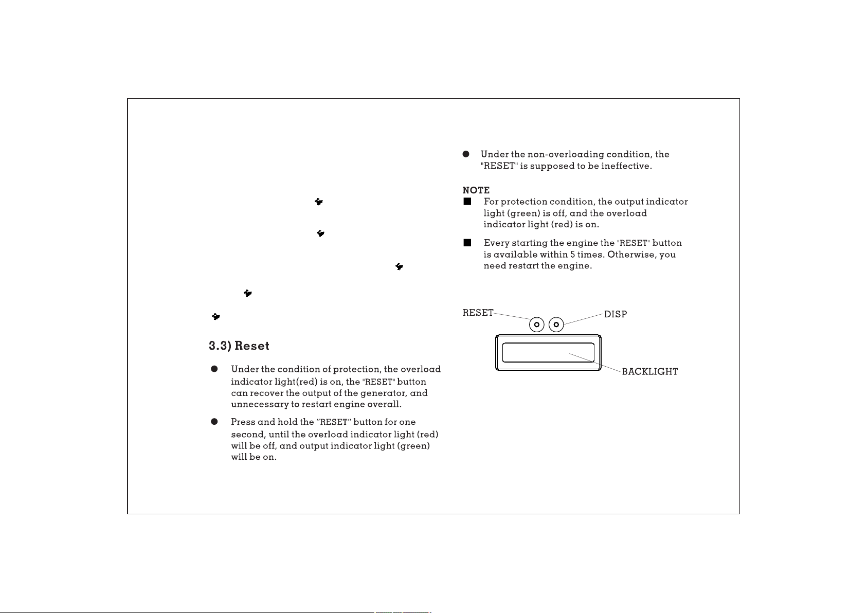
3)Res et
4)Hou rmete r
04.Pre-operation check
1)Che ck oil le vel
2)Che ck fuel l evel
3)Che ck air cl eaner
05.Starting the engine
06.Generator use
1)DC ap plica tion
2)AC appli catio n
3)Out put and o verlo ad indi cator
4)Oil a lert sy stem
04
06
07
08
08
09
09
10
10
11
12
13
15
16
18
18
19
07.Stopping the engine
08.Maintenance
1)Cha nge oil
2)Air c leane r service
3)Spa rk plug s er vice
4)Spa rk arre ster ma inten ance
09.Transporting/Storing
10.Troubleshooting
11.Technical specifications
12.Wiring diagrams
13.Appendix
1)Env ironm ent cor recti on
2)Noi se and ac cess
14.Consumer information
20
21
21
22
24
25
27
29
30
31
32
32
33
34
Page 6

Page 7

1.SAFETY INFORMATION
To ensure personal and property safety, please
carefully read the following information.
distance wi th constructi ons and other
electrica l appliances at l east.
● Place the generator on the leveled surface, in
order to avoid overturning or spilling fuel.
WARNING
● Read and understand the user manual before
using the generator.
● The emission of engine contains poisonous
carbon monoxide. Use the generator in well
ventilated conditions.
● Do not touch the hot muffler, when the generator
is running, or before cooling.
● Petrol is explosive and flammable in the specified
conditions when refueling, the generator needs to
be stopped and be kept cigarette and fire source
away.
● Do not connect to the building’s electrical system
or other generator, in order to avoid the electric
shocks and fires.
● The running generator must keep one meter
● Children and pets should be
operation area.
● Do not operate with wet hands.
● Do not expose the generator to rain, moisture or
snow.
● Place the generator at least 1m away from
buildings or other equipments during
operation.
● The major repair work should be carried out
only by professionally trained person.
● Do not use the generator in underground
working
● Do not use the generator in potentially
explosive atmospheres
● Use personal protective equipment: glove,
mask, earplugs, when you operate
keep away the
<<04>>
Page 8
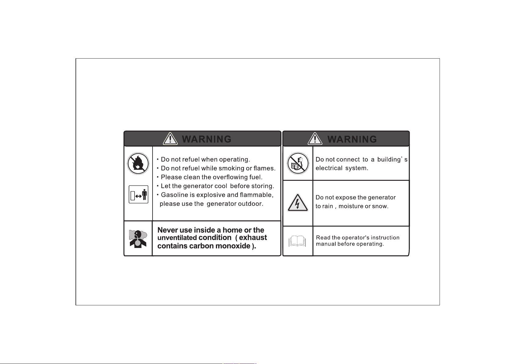
SAFETY LABEL:
<<05>>
Page 9
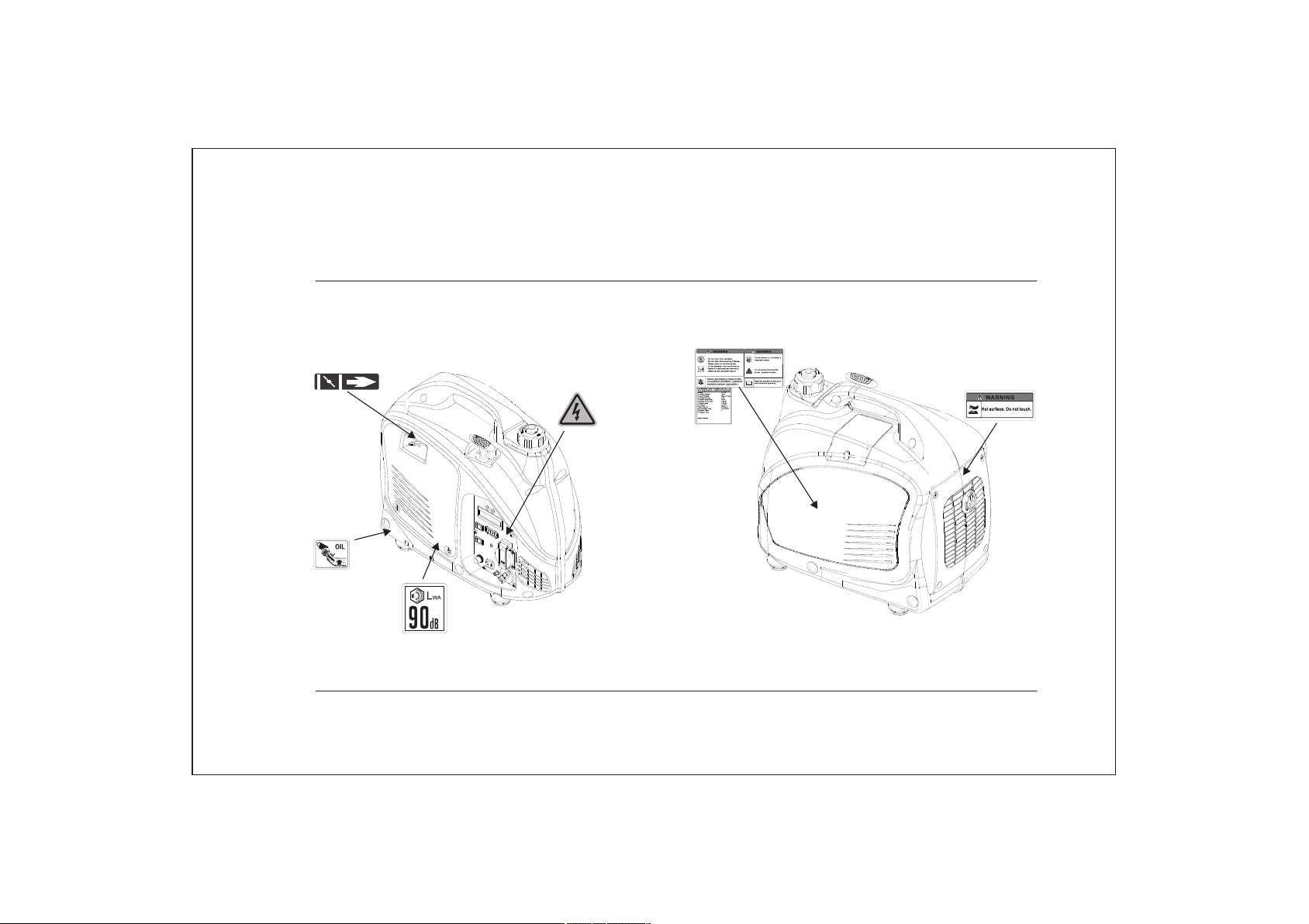
2. SAFETY LABEL LOCATIONS
<<06>>
Page 10
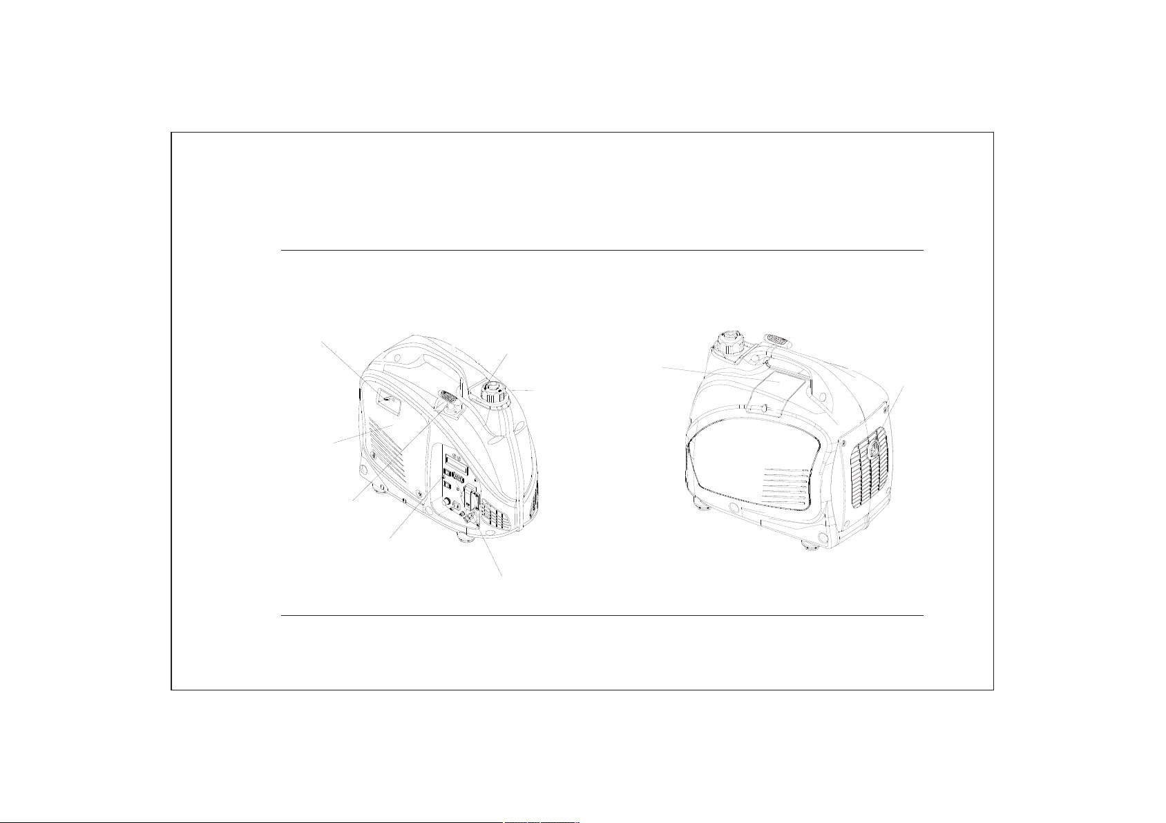
3. C IDENTIFICATIONOMPONENTS
CHOKE LEVER
AIR CL EAN ER
MAINTENA NCE
COV ER
STARTER GRI P
ENGINE SW ITC H
FUEL C AP VENT LEV ER
FUEL C AP
CONTROL
PANE L
SPAR K P LUG
MAINTENA NCE
COV ER
MUFFLER
<<07>>
Page 11
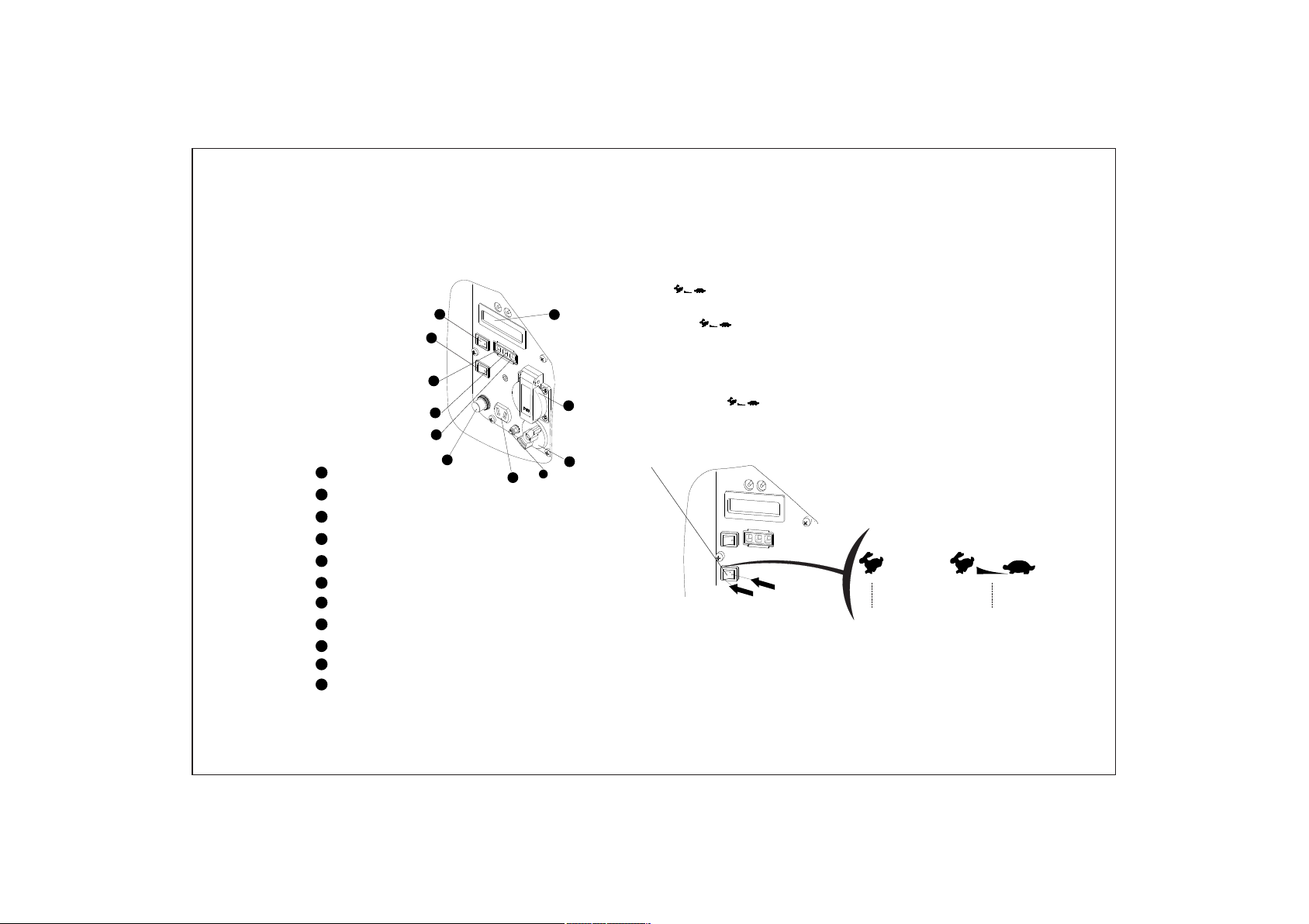
3.1) Control Panel
11
1
2
3
4
1
ECON. SW
Oil Alert Indicato r L ight(red)
2
Overload Indicato r Light(red)
3
Output Indicator Light( green)
4
5
DC Cir cuit Protector
DC Rec eptacle
6
7
Ground Terminal
8
Fuel Switch
9
AC Rec eptacle
10
Hourmeter
11
Engine Switch
5
3.2) ECON. SW (Economy control switch):
“ON”( )
10
9
8
7
6
● When the econo my control swi tch is turned to
“ON”( ), the engine keep s running at idle state
automatic ally whe n the ele ctrical appl iance is
disconnec ted,and it will retur n t o the pro per speed
with the requi rement of electrical load.
● The “ON ”( ) is recommen ded to minimize the fuel
ECON. SW
ON
OFF
ONOFF
<<08>>
Page 12
NOTE
■ When a high loa d electrical appliance is
connected i nstantaneou sly, in order to reduce
voltage cha nge, turn the eco nomy contro l
switch to the “OFF”( )position .
■ In DC operation, turn the ec onomy control
switch to the “ OFF”( )position.
■ Connect bot h AC load a nd DC load, tur n the
economy con trol switch to th e “OFF” ( )
position.
“OFF” ( )
When the econ omy control switch turns to th e “OFF”
( ) engine runs at high speed.
3.4) Hour-meter
● Pre ss the “DISP ” button to display the
voltage/frequency of output, the engine speed
and cumulative working time in turn.
● Pre ss the “DISP ” button, the back-light of hour-
meter will be on, and it will be off wit hout
operating the button for 10S.
<<09>>
Page 13

4. PRE- OPERATION CHECK
WARNING
Be sure the gen erator is on the le veled surfa ce and
the generat or is stopped.
4.1) Check Oil Level
Remove the oi l filler cap, and t hen clean it wi th
cloths. Rei nsert it into the c rankcase, a nd take out
to check oil le vel:
If the oil leve l reduces at the bo ttom of the oil f iller
cap, add the en gine oil.
Oil Cap acity:0.25L
NOTE
■ Using non-d etergen t or 2-stroke oil could
shorten the e ngine’s working life.
■ Using the hig h quality engine oil with stro ng
detergents
■ Using 4-str oke engine oil, certified to m eet or
exceed API st andards: SG, SF , SE stickine ss
rating:
15W -40
10W -40
10W -30
5W- 30
OIL FILLER
CAP
DIPSTICK
OIL FILLER H OLE
UPPER LEVE L
-30 -20 - 10 0 10 20 3 0
-20
20 40 60 80
0
40℃
100 F
NOTE
Carefully u se and store the en gine oil, avo id
getting dir t or dust into the en gine oil.
Mixing diff erent kinds of engine oil is pro hibited.
<<10>>
Page 14

NOTE
■ Before the en gine oil reduces below the saf ety
margin, low oil alert sy stem will close the
engine auto matically. The oil alert ind icator
light (red) will be on.
■ To avoid t he inconvenience caused by
unexpecte d stopping, it is still advisa ble to
check the eng ine oil level regularly.
FUEL CAP
WARNING
OPEN
UPPER LIMI T MAR K
Fuel c apa cit y: 3.8L
4.2) Check Fuel Level
Fuel recommend: use unleaded petrol
(Research Octane Number of 91 or higher, Pump
Octane Number of 86 or higher).
Never use sta le or contamina ted gasolin e or an
oil/gasol ine mixture.
Avoid getting dirt or water into the fuel tank.
Do not use a mixture petrol containing ethanol or
methanol; otherwise, it will seriously damage the
engine.
● Petrol is extremely explosive and flammable.
● Around the refueling area and fuel storage
area, prohibit smoking and firing.
● Do not overfill the fuel tank (no fuel above the
red upper limit mark). After refueling, make sure
the fuel cap is closed properly and securely.
● Do not spill fuel from fuel tank. (No residual fuel
around the neck of tank, before starting engine)
● Avoid contacting with skin or breathing the fuel
vapor.
● KEEP OUT OF REACH OF CHILDREN.
<<11>>
Page 15

4.3) Check Air Cleaner
Check the air c leaner element to be sure it is cl ean
and in good con dition.
a. Loosen the a ir cleaner maintenance cov er
screws, and r emove the cover.
AIR CLEANER ELEMENT
AIR CLEANER MAINTENANCE
COVER
COVER SCREW
b.P ress the latch t ab on the top of the ai r cleaner.
AIR CLEANER
COVER
c.R emo ve the air cleane r cover.
d. Check the ele ment, clean or re place it, if ne cessary.
NOTE
■ Do not run engi ne without air Cleaner
element, ot herw ise that make s engine
<<12>>
Page 16

5. STARTING THE ENGINE
NOTE
■ Before st arting engine , disconnec t load with
AC re ceptacle.
NOTE
■ When transp orting generator, turn th e fuel
cap vent leve r to the “OFF ” po sition.
■ Fuelin g at the first time , refueling , or storing
for a long time , the engine swit ch should
firstly be op ened for ten or twe nty seconds
and then requ ire additional pull 10-20 ti mes,
in order to the e nough fuel ente r into
carbureto r.
5.1) Turn the fuel ca p vent lever to t he “ ON”
position.
FUEL CAP VEN T LEV ER
OFF
O
N
ON
OFF
ON
ENGINE SWI TCH
5.3) Move the c hoke lever to “CLOSED” position .
CHOKE LEVE R
CLOSED CLOSED
<<13>>
Page 17

NOTE
■ Do not move the c hoke lever to “CLOSED”
position, w hen engine is hot or ambient
temperatu re is high.
5.4) Pull t he starter gr ip lightly unti l you feel
resistanc e, then pull quic kly toward ar row as
shown below.
STARTER G RIP
5.5) After st arting and warm ing up the engi ne,
turn the chok e lever to “OPE N” positi on.
CHOKE LEVE R
NOTE
■ Return the st arter grip slow ly by hand. Do no t
make the star ter grip spring b ack quickly.
OPEN
OPEN
NOTE
■ If the gene rator stops and c an not restart,
check the oil l evel firstly.
Carbure tor Modificat ion for High Alti tude
Operation
At high altitude, the st andard carburetor airfuel mixtur e will be too rich. Perf ormance will
decrease, a nd fuel consump tion will inc rease. A
very rich mixture will also foul t he spark plug
and cause har d starting.
If the genera tor operates at h igh altitud e,
change the ma in-nozzle or ad just the idling-
<<14>>
Page 18

screw
of carburet or.
the generator always operates at altitude
If
above 1,000 meters, contact with an authorized
Cobra servicing to modify the carburetor.
Generator output power should be modified
according to the altitude and ambient
temperature. The correction factor refers to
13-1.
6. GENERATOR USE
WARNING
● Be sure to grou nd the generato r when the
connected e lectrical app liance is gro unded.
● Do not conn ect to the buildi ng’s electrical
system, in or der to avoid the el ectric shoc ks
WARNING
● If the carburetor has been modified for high
altitude operation, the air-fuel mixture will be too
lean for low altitude use. Operation at low
altitude may cause the engine to overheat and
result in serious engine damage. The carburetor
needs return to original settings
GROUND TER MIN AL
<<15>>
Page 19

WARNING
6.1) DC Application
● For contin uous operatio n, do not excee d the
rated out-p ut power of gener ator.
● Do not make par allel connect ion with othe r
generator s.
● Do not connec t an extension to t he exhaust
pipe.
● When an exten sion cable is req uired, be sur e
to use a tough ru bber sheathed f lexible cab le
(accordin g to IEC245 or equivalent
standards ). The length of th e extension c able:
60m for cable o f 1.5mm ; 100m for cable of
2.5mm .
2
2
● Kee p away from other electric cab les or wires.
NOTE
■ The AC recept acle can be use d while the DC
power is in use . If use both at same t ime, be
sure not to exc eed the total pow er for AC and
DC. (AC:0. 9kVA,DC:5 A)
■ Most of motor a ppliances req uire more tha n
their rated w attage, when st arting.
The DC receptacle, 15-30V under no-load condition,
may be used for charging 12V battery only.
NOTE
■ In DC operati on, turn the EC ON.SW t o the
"OFF” ( ) position.
6.1.1) Conn ect the DC rece ptacle to batte ry
CHARGING C ABL E
<<16>>
Page 20

WARNING
WARNING
● In order to avo id producing the spark at the
terminals o f battery, connect the charging
cable first ly to the battery ter minals, and the n
to the genera tor. Disconn ect the cable f irstly
at the genera tor .
● Before conn ecting the charging cable to a
battery that is ins talled in veh icle,the
grounded ca ble of battery will b e
disconnec ted firstly. Th is sequence w ill
prevent spa rks or short-ci rcuit. When t he
cable accid entally conta ct the vehicl e’s frame
NOTE
■ Do not start the automobile engine when the
generator is still connected to the battery,
otherwise the generator will be damaged.
■ Connect the positive battery terminal to the
positive charging cable. Do not
reverse the
charging cable.
● The battery can rel ease the expl osive gases.
Kee p the battery away fr om spark/fire .
Charge the battery in ventil ated condit ion.
● Battery electro lyte contai ns sulfuric aci d
that will cau se severe burn of s kin and eyes.
Therefore i t is necessary to wea r the
protectiv e clothing and mask.
● If battery electr olyte gets in to eyes, flush
thoroughl y with warm water for 15min at
least, and ca ll a doctor immed iately.
● If you swallo w a little of batte ry e lectrolyte
accidenta lly, flush thor oughly with w ater
your mouth, a nd then drink large quanti ties
of water or mil k (with magnesia or vegetabl e
oil), and cal l a doctor immediately.
NOTE
■ The DC recept acle can be used wh ile the AC
power is in use
■ When DC circu it overload will trip the DC
<<17>>
Page 21

circuit pro tector, remo ve load first ly, and
then reset th e protector aft er a few minute s.
OVE RLOAD
INDICATOR
LIGHT(RE D)
OUTPUT
INDICATOR
LIGHT (GRE EN)
ON OFF
DC protect or
6.2) AC applications
6.2.1) Start engine and make sure the output
indicator light (green) is on.
6.2.2) Confirm all electrical appliances are switched
off, and connect the appliance plugs to the
generator receptacle.
NOTE
■ To obtain the best working and longest working
life of the generator, a new generator is run for 20
hours at 50% rated load.
NOTE
PLU G
■ Confirm all e lectrical appliances are i n
good workin g condition before connect ing
them to the gen erator. If an el ectrical
appliance b ecomes abnormal, sluggis h, or
stops sudde nly, shu t off the gener ator
engine imme diately, and discon nect the
6.3) Output and Overload Indicator
In normal ope rating, outpu t indicator l ight
(green) wil l remain on.
If the genera tor is overload ( over 0.9 kVA), or the
connected a ppliance is sho rt-circui t, the output
indicator l ight (green) is off, and overl oad
<<18>>
Page 22

indicator l ight (red) is on. The AC power will be
switched of f, but engi ne is still runni ng.
If the overlo ad indicator light (red) is on , disconnect
the electri cal appliance s firstly, press and ho ld the
rest button 1 s. If the overloa d indicator l ight (red) is
OFF and the out put indicator l ight (green ) is on,
reconnect t he electrical a ppliances . Otherwise stop
the engine an d check the generator.
6.4) Oil alert system
The oil alert s ystem is designed to prevent e ngine
damage caus ed by an insuffic ient amount o f oil
in the crankc ase. Before the o il level in the
crankcase f alls below a safe l imit, the oil a lert
system will a utomatically shut down the e ngine
(the engine s witch remains in the “ON“position).
OVE RLOAD
INDICATOR
LIGHT(RE D)
OUTPUT
INDICATOR
LIGHT (GRE EN)
If the oil aler t system shuts do wn the engine , the
oil alert ind icator light (red) will be on. C heck the
engine oil le vel.
OIL ALERT IND ICATOR
LIGHT ( RED)
<<19>>
Page 23

7. STOPPING THE ENGINE
7.3) Turn the fuel cap vent lever to the“OFF”
position.
To stop the eng ine in an
emergency, turn the en gine
switch to the “ OFF”position.
7. 1) Switch off t he connected
electrica l appliances,
and pull out th eir plugs.
PLUG
7.2) Turn the engine switch to the “ OFF” positi on.
FUEL CAP VEN T LEV ER
OFF
OFF
NOTE
■ Be sure the fuel cap vent lever and engine
switch locate the “OFF” position,
when
stopping, transporting and storing the
generator.
■ Avoid transporting the generator with fuel
still in the tank.
ON
<<20>>
Page 24

8.
MAINTENANCE
The purpose of the maintenance and adjustment
schedule is to keep the generator in the best
operating c ondition.
WARNING
Stop the engi ne before performing any
maintenan ce. If the engine m ust run, be sur e the
area is well ve ntilated. The exhaust cont ains
poisonous carbon monoxide gas.
Use genuine Cobra or equivalent quality
components to replace the wear components.
Maint enanc e Sched ule
Reg ular Se rvic e
Per iod (3 )
Ite m
Eng ine
oil
Air
cle aner
Spa rk plug
Check level
Cha nge
Che ck
Cle an
Check-adjust
Eac h
use
Fir st
mon th
or
10 hr s.
Eve ry 3
mon ths
or
50 hr s.
+(1)
Eve ry 6
mon ths
or
100 h rs.
Eve ry
2 yea rs
or
300 h rs.
Spa rk plug
Spark arre ste r
Valve Clearance
Combustion Chamber
Fuel tank& filter
Fuel l ine
Rep lace
Check-adjust
Cle an
Cle an
Che ck
⊙
+(2)
Aft er ever y 300 hr s(2)
Eve ry yea r(2)
Eve ry 2 yea rs ( Rep lace if n ecess ary) (2)
NOTE
(1) Service more frequently when used in dusty areas.
(2) These items should be serviced by your servicing
dealer, unless you have the proper tools and are
mechanically proficient. Refer to Cobra manual for
service procedures.
(3) For commercial use, long hours of operation to
determine proper maintenance intervals.
8.1) Change Oil
Drain the oil r apidly and completely whil e the
engine is sti ll warm.
8.1.1) Loos en the air cleane r maintenan ce cover
screw, and remove the cov er.
8.1.2) Remo ve the oil filler cap.
<<21>>
Page 25

8.1.3) Drai n dirty oil into a container tho roughly.
8.1.4) Refi ll the recommended oil and che ck the oil level.
8.1.5) Rein stall the oil filler cap.
8.1.6) Rein stall the maint enance cove r and tighten the
cover screw.
OIL FILLER H OLE
UPPER LEVE L
AIR CLEANER MAINTENANCE
COVER
COVER SCREW
OIL FILLER
CAP
NOTE
After oil change, wash your han ds with soap.
NOTE
For conforming to the environment requir ement,
the used oil will be put into a sealed container and
then be transport ed to the service station fo r
recycler. Do not throw it into the trash or po ur it on
the ground.
Oil Capacity: 0 .25L
8.2) Air Cleaner Service
A dirty air cle aner will restrict air flow in to the
carbureto r.Clean and maintain the air c leaner
regularly, especi ally in the ext remely dusty ar eas.
<<22>>
Page 26

WARNING
Do not use petrol or low ignition point solvents for
cleaning. They are flammable and explosive under
certain conditions.
NOTE
Never run the g enerator
without air c leaner,
otherwise that re sult in engin e abrasion rapi dly.
8.2.1) Loos en the air cleaner maintenan ce cover
screws, and r emove the cover.
AIR CLEANER MAINTENANCE
COVER
COVER SCREW
8.2.2) Press down the latch tab on the top of the air
cleaner, and open the air cleaner cover.
AIR CLEANER ELEMENT
AIR CLEANER
COVER
8.2.3) Take out the air cleaner element, and clean
it with non- flammable or high flash point
solvent, then dr y it.
8.2.4) Soak the air cleaner element in the clean
engine oil, and squeeze out the redundant
oil.
ELEMENT
<<23>>
Page 27

8.2.5)Reinstall the air cleaner element and cover.
8.2.6)Reinstall the maintenance cover, and tighten
the screws.
8.3) Spark Plug Service
Recommendation spark plug: CR7HSA, A5RTC
Check the spa rk plug gap and c lean the carbon
depositio n at the bottom o f the spark plu g.
8.3.1) Loos en the spark pl ug maintenance cover
screws, and remove the c over.
SPAR K PLUG
MAINTENANCE COV ER
8.3.2) Take off the spa rk plug cap.
8.3.3) Clean th e carbon depositi on at the botto m of
the spark plug.
HANDLE BAR
SPAR K PLUG CAP
8.3.4) Take off the spark plug with the spark plug
spanner.
8.3.5) Visual inspection the spark plug. Change a
new one if its insu
lator cracked or chipped.
Clean it with a wire brush if the spark plug
is reused.
0. 60- 0.70m m
(0.024-0.028in)
<<24>>
Page 28

8.3.6) Meas ure the spark plu g gap with a feel er
gauge. The no rmal value:0. 6-0.7mm(0 .024-
0.028in). A djust the gap by be nd one of the
electrode c arefully.
8.3.7) Rein stall the spark p lug careful ly, by han d,
to avoid cros s-threading. A new spark plu g
should be tig htened 1/2 turn with a spanner.
A used Spark pl ug should be tigh tened 1/8 to
1/4 turn with s panner.
8.3.8) Rein stall the spark p lug cap
8.3.9) Rein stall the spark p lug mainten ance cover.
NOTE
■ The spark plug must be securely tightened.
Tightening in wrong way will cause spark plug
hot, even damage the engine.
■ Never use a spark plug with an improper heat
range.
8.4) Spark Arrester Maintenance
WARNING
The spark arr ester must be mai ntained eve ry
100h service.
8.4.1)Rem ove the four scre ws, and remov e the
muffler gua rd.
<<25>>
Page 29

8.4.2)Tak e off the spark arr ester from th e muffle after
the engine co ol down.
8.4.3)Rem ove carbon deposits of the spa rk arrester
using a brush . If the spark arre ster is wear,
replace it.
8.4.4)Rei nstall the spar k arrester an d muffle
guard.
<<26>>
Page 30

9.TRANSPORTING/STORING
Avoid fuel sp illing during transporti ng or
temporary stori ng, both the en gine switch and t he
fuel cap vent l ever should tur n to “OFF’ posi tion,
and the gener ator should pla ce in normal
operating p osition.
WARNING
Tran sporting Gene rator:
● Do not overfill the fuel tank. (No residual fuel on
the neck of tank) It is recommended to drain the
generator of fuel before transporting.
● Do not use the generator on the transport vehicle.
The generator should be used under a good
ventilated condition.
● Avoid exposing directly in the sunshine when the
generator place in the enclosed transport vehicle
for a long time.
vehicle could cause fuel to vaporize resulting in a
possible explosion.
● Drain off the fuel, when the generator is
transported on rough road.
The high temperature inside the
Storing for a long period:
9.1) Make sure the storage area without excessive
humidity and dust.
9.2) Drain off the fuel.
WARNING
● Kee p away from smoking, flames an d spark,
gasoline is e xplosive and flammable in th e
specified c ondition.
a.
Drain off the petrol in the fuel tank,storing
into the suit able containe r.
<<27>>
Page 31

b. Turn the engine switch to “ON” po sition, and
loosen the ca rburetor drain screw to disc harge
c. Take off the s park plug cap, pu ll the starter grip
three or four t imes, discharge the gaso line from
the fuel pump a nd fuel lines.
d. Turn the engine switch to “OF F” position, an d
tighten the d rain screw of car buretor.
e. Reinstal l the spark plug ca p.
STARTER G RIP
9.3) Change t he engine oil.
9.4) Remove t he spark plug, an d pour a
tablespoo n of clean engine o il(10~20ml)into
the cylinde r. Revolve the e ngine sever al
times to dist ribute the oil,and reinsta ll the
spark plug.
9.5) Pull the starter gr ip slowly until f eel
resistanc e. At this po int, the piston i s coming
up on its compr ession stroke a nd both the
intake and ex haust valves ar e closed. In th is
position, i t helps to protec t the engine fr om
internal co rrosion.
<<28>>
Page 32

10.TROUBLESHOOTING
Appliance does not operate:
When the engine can not be started:
Is there fuel in the tank?
YES
Is the engine switch O N?
YES
Is the fuel cap vent lever ON?
YES
Is the choke lever OPEN?
YES
Is there enough oil in the
engine?
YES
Is the spark plug in good
condition?
YES
Refill the fuel tank
NO
Turn the engine switch on
NO
Turn the fuel cap vent lever on
NO
Turn thechoke lever to OPEN
NO
Add the recommended oil
NO
Clean, readjust gap
and dr y the s par k plug.
NO
Replace it if necessary
Is the output indicator
light ON?
Is the overload indicator
YES
light ON?
YES
Check the electrical
appliance for any fault.
YES
NO
NO
Contact with an
authorized Cobra
NO
dealer
Contact with an
authorized Cobra
dealer
Stop engine and then replace or repair the appliance
Restart the engine
DC receptacle without any electricity:
Check the electrical appliance
for any fault
NO
Is the DC circuit
protector ON?
Change or replace the appliance
YES
YES
Pus h the D C circuit
protector ON.
NO
Contact with an
authorized Cobra
dealer
<<29>>
Page 33

11. TECHNICAL SPECIFICATIONS
Speci ficatio ns
Model
Type
Engine Displacement
Bore*Stroke
ENGIN E
Compression Ratio
Rated Speed
Ignition Syst em
Start Syst em
Fuel Ty pe
Oil Capacity
Model
GENERATOR
Rated Frequency
Rat ed Vol tag e
Rat ed Cu rrent
Rated Speed
Rated Output Power
Max. Output Power
Par ameters
IG10SI - HS1200i.1
4-str oke, ov erhea d valve ,
single cylinder, forc ed-ai r cooling
3
53.2cm
43.5mm*35.8mm
7.6:1
-1
5500min
Recoil starte r
Gasoline withou t lea d
0.25L
SE 15W-30Oil Model
IG
10si
50Hz
230V
3.9A
-1
5300min
0.9kVA
1.0kVA
DC Output
Fuel Tank Volume (L)
Continuous Running Time(h)
GENERATOR SE T
Fuel Consumption (g/(kW.h)
Working Ambient Temperature( )
Max. Altitude (m)
﹡Noise (dB/4m) L
﹡﹡ Noise (dB /7m ) L
Dimensions (L*W*H )(mm)
Net Weight(kg)
12V/5A
3.8
5h (rated power)
550
-20~4 0
1000
90
wA
54~59
pA
279*425*443
14
12V/5A
Noise level is measured when the ECON.SW is turned
to ‘’ ON‘’( )
L shows the guaranteed sound power tested
wA
by 2000/14/EC.
The noise level in “dB/7m” is the
arithmetic mean value of sound press level (L ) in
pA
four directions measured 7 meters away from the
generator.
The noise level may vary in different environments.
<<30>>
Page 34

12.WIRING DIAGRAMS
<<31>>
Page 35

13. APPENDIX
13.1) Environment Correction
The standar d condition of ra ted power out put:
Altitude: 0m
Ambient tem perature:25 C
Relative hu midity:30%
Factor of en vironment correction:
Altitude (m)
0
500
1000
2000
3000
4000
25 30 35 40
1
0.93
0.87 0.85 0.82 0.80 0.78
0.75 0.73
0.64 0.62 0.60 0.58 0.56
0.54 0.52 0.50 0.48 0.46
o
Ambient te mpe rat ure℃
0.98 0.96 0.93 0.90
0.91
0.89 0.87 0.84
0.71
0.69 0.66
NOTE:
Relative hu midity 60% corr ection fact orC-
0.01;
Relative hu midity 80% correction
factorC -0. 02;
Relative hu midity 90% correction fact orC-
0.03;
Relative hu midity 100% correctionfa ctorC-
0.04;
Example:
45
1000m) Ambi ent temperature: 35℃,Relative
Rated power(P )0.9kVA ge nerator(Alt itude:
N
humidity: 8 0%
P=P *(C-0.02)=0. 9* (0.82-0.02) =0.72kVA
N
<<32>>
Page 36

13.2) Noise and Access
Noise emission measure according to ISO 8528-10,
EN ISO 3744, European Directive 2000/14/EC with
amendment 2005/88/EC
Model of generator set:
Sound Pressure Level: 68 dB(A)
Guaranteed Sound Power Lever:90dB(A)
Measurement Uncertainty K: 1.7 dB(A)
The quoted figures are emission levels and are not
necessarily safe working levels. Whilst there is a
correlation between the emission and exposure
levels, this cannot be used reliably to determine
whether or not further precautions are required.
Factors that influence the actual level of e xposure
of work-force include the characteristics of th e
work room, the other sources of noise, etc, i.e. the
number of machines and other adjacent
processes, and the length of time fo r which an
operator is exposed to the noise. Also the
permissible exposure level can vary from county.
This information, however, will enable the user of
the machine to make a better evaluation of t he
hazard and risk.
<<33>>
Page 37

14. CONSUMER INFORMATION
Consumer Service Information
Please contact your retailer for any service related issues in the first instance.
As appropriate you may be referred to another Cobra dealer who is professionally trained to complete service
work as necessary. The Cobra dealer list is available at cobragarden.co.uk or contact 0115 986 2161 for
assistance.
When contacting your dealer, please have the following
Model and ser ial number
Date of purch ase
Detailed description of the problems
Dealer contact information and your
: name, address, and telephone number
information to hand:
<<34>>
Page 38

We herewith declare, Cobra Garden Machinery
Henton & Chattell Ltd, London Road, Nottingham NG2 3HW United Kingdom
that the following machine complies with the appropriate basic safety and health requirements of the EC
Directive based on its design and type, as brought into circulation by us.
In case of alteration of the machine, not agreed upon by us, this declaration will lose its validity
Machine Description: Inverter Generator
Machine Type: IG10SI (HY10i)
Engine Displacement: 53.2 cm
3
Rated Output Power 0.9kVA Max 1.0kVA
Measured sound power level 68 dB(A)
Guaranteed sound power
level:
90 dB(A)
Notified Body for EC Directive 2000/14/EC:0499
TÜV Rheinland LGA Products GmbH
Tillystrasse 2, 90431 Nürnberg, Germany 0197
Applicable EC Directives: 2006/42/EC
2006/95/EC
2004/108/EC
2000/14/EC amended 2005/88/EC
Applicable Harmonized
Standards:
EN 12601:2010
EN 61000-6-2:2005
EN 61000-6-4:2007
Authorized Signature/Date/
Place:
Peter J. Chaloner 10/1/2019
EC DECLARATION OF CONFORMITY
Title of Signatory: Managing Director
Name and address of the
person authorized to
compile the technical file
Cobra Garden Machinery
Henton & Chattell Ltd, London Road, Nottingham NG2 3HW United Kingdom
Page 39

Cobra Garden Machinery
Henton and Chattell Ltd, London Road, Nottingham
NG2 3HW UK
 Loading...