

Page 1
* Cobra recommends you always wear a helmet while riding. Please never operate your motorcycle while under
1 – Fi2000R Fuel Injection Module
HARLEY 95
-Up
FLH
Read all instructions ca
refully and completely before installing your new Fi2000 module.
692-1600
Page
1
of 4
23801 E. La Palma Ave., Yorba Linda, Ca 92887 Ph. 714.692.8180 Fax. 714.692.5016
www.cobrausa.com
Items Supplied >
2 – Zip Ties
Application(s) >
W/Fuel Injection FLHT
FLHS
FLTR
ROADKING
Instruction Manual >
It is recommended that a qualified mechanic or technician install this product.
1. Remove the seat and air cleaner assembly.
2. Remove both front and rear gas tank mounting bolts.
3. Prop the rear of the gas tank up approximately 2”.
4. Locate the factory connector on each fuel injector. Depress the wire clip on the injector and pull
the connector free and move out of way. Note: A pair of needle nose pliers and a long flat blade
screwdriver helps with this job. If you have a 2002 or newer Harley see the additional instructions
on sheet 2.
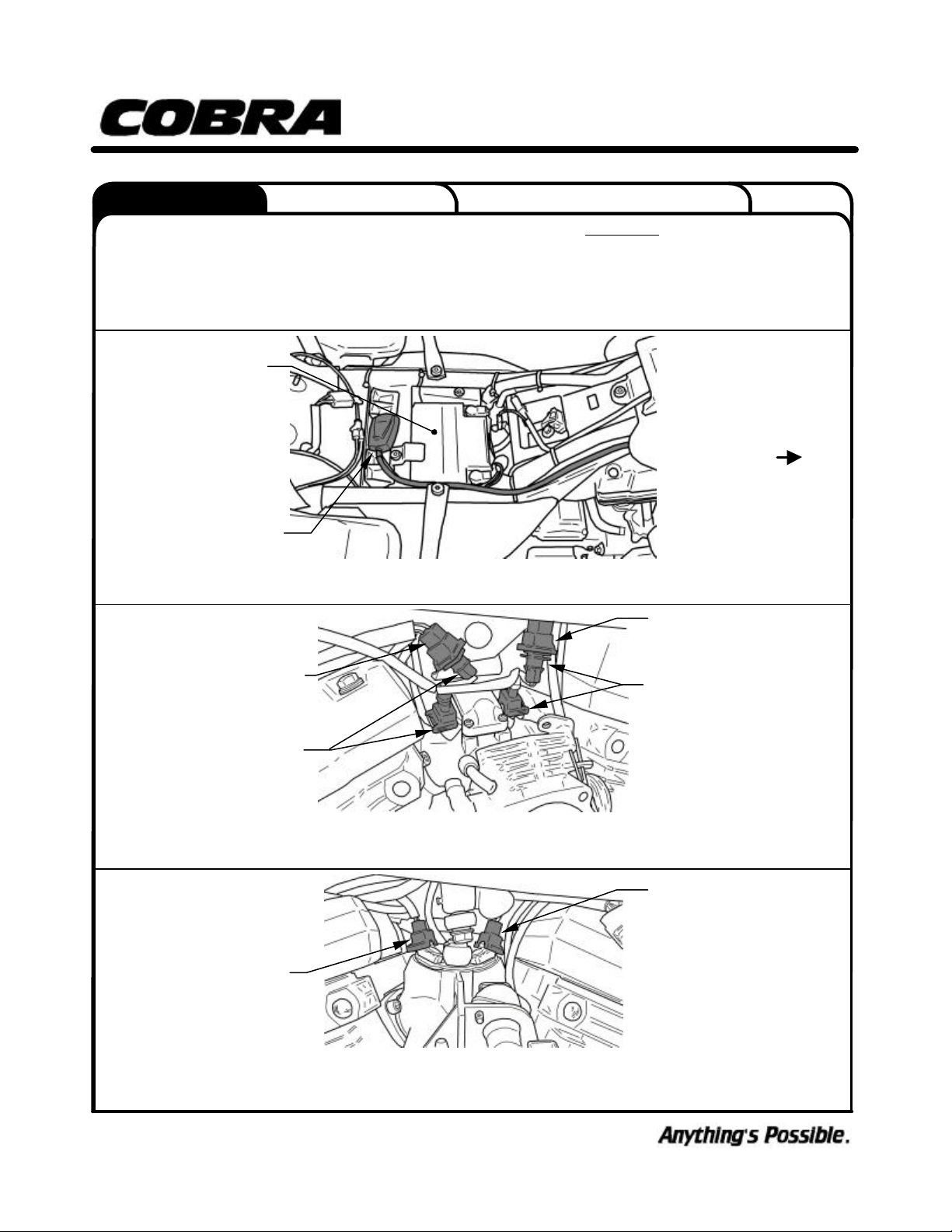
5. Lay the Fi2000 module in place, but do not attach it to the motorcycle, and run the wiring harness
up to the manifold area behind the other wiring of the throttle body (See figure 1). Attach the
Fi2000 module’s forward injector plug, with the grey and red wires, onto the front injector. Then
take the original HD connector and insert the corresponding Fi2000 connector, with the brown and
red wires, into it. (For model years 02’ and Up refer to figure 2, for model years 95-01 refer to
figure 3)
6. Attach the Fi2000 module’s rear injector plug, with the blue and red wires, onto the rear injector.
Then take the original HD connector and insert the corresponding Fi2000 connec tor, with the
green and red wires, into it. (For model years 02’ and Up refer to figure 2, for model years 95-01
refer to figure 3)
7. Before re-installing the gas tank, seat and air cleaner assembly, verify your connections. Remove
the door from the Fi2000 box to expose the LED’s. Verify the wire connections by (1) turning the
ignition on, prior to starting, and see if all three LED’s are on steady. If you have no light, your
ground connection (BLACK wire) has not made proper contact or your front injector connection is
not complete. (2) After achieving a steady light from all three LED’s, start the motorcycle, wait 15
seconds and let it idle, the green light should now be the only LED on. If all three LED’s are still on
after start up, verify you have attached the injector connectors correctly. Reattach the door when
finished. Note: Make sure the ignition is turn off before changing any connection.
8. Route the Fi2000 wiring harness along side the factory harness using the supplied zip ties,
keeping it off the cylinder head or getting it pinched under the gas tank. Lower and re-attach the
fuel tank.
9. Remove the backing from the Velcro and attach the Fi2000 next to the battery as shown in fig 1.
10. Re-install the seat and air cleaner assembly.
the influence of alcohol and/or drugs. Enjoy the new look of your motorcycle and please ride safely.
DOCUMENT NO. 0017 REV. A
12/04
Page 2
692-1600
The following instructions apply to the
02 and Up
DOCUMENT NO
.
0018 REV. A
(02’ and Up shown, 95’
–
01’ similar)
Fi2000 MODULE
FRONT Fi2000 INJECTOR
ORGINAL FRONT HD
REAR Fi2000
INJECTOR
ORGINAL REAR HD
FRONT
ORGINAL REAR HD
ORGINAL FRONT HD
23801 E. La Palma Ave., Yorba Linda, Ca 92887 Ph. 714.692.8180 Fax. 714.692.5016
Instruction Manual >
1. If you need additional access to the fuel injector connectors, you can remove the Idle Air
solenoid by removing the two 5/16’’ bolts holding it on and loosening the Torx #20 screw on
throttle cable bracket. Make sure to use locktite when refitting the two 5/16” bolts and correctly
position the o-ring when reattaching.
BATTE RY
FIGURE 1
www.cobrausa.com
Page 2 of 4
INJECTOR CONNECTOR
CONNECTORS
INJECTOR CONNECTOR
INJECTOR CONNECTOR
CONNECTORS
FIGURE 2
(02’ and Up W/Fi2000 installed and Air Injector Solenoid removed)
INJECTOR CONNECTOR
FIGURE 3
(95’ – 01’ W/O Fi2000 installed)
12/04
Page 3

692-1600
DOCUMENT NO
. 0018 REV. A
23801 E. La Palma Ave., Yorba Linda, Ca 92887 Ph. 714.692.8180 Fax. 714.692.5016
Instruction Manual >
TUNING NOTES
Typically 2 into 1 exhaust systems require one additional position, on the yellow and red pots, over
slip-ons.
ADVANCED TUNING
Your Cobra Fi2000 fuel injection module has been tested and preset for best function and rideabilty
on a stock motorcycle with a Cobra exhaust. The Fi2000 does however, have 3 important
adjustments that allow you to tune the module for optimum performance, especially if you have
performed other changes to your motorcycle. These adjustments also allow you to resolve
drivability issues if our stock settings are not exactly right for your bike. Make sure your motorcycle
is up to normal operating temperature (15 minutes of riding should be sufficient) before making any
adjustments. Remove the door to expose the pots shown in figure 4.
GREEN LED POT (left pot) - this adjustment affects idle and cruise fuel. If you have cruising
issues, this is where you would try a different setting. Generally, surging and uneven running while
cruising is a lean fuel condition, so try adding a small increase in fuel by turning the adjustment
clockwise with a small flat blade screwdriver a 1/2 of a position. Test drive the bike to feel an
improvement and only increase the setting until the surge goes away. Also, backfiring or popping
on trailing throttle is generally a lean symptom (or an exhaust gasket leak). Try the same small
increases as above just until the backfiring goes away.
YELLOW LED POT (middle pot) - this adjustment affects acceleration and power fuel. If you have a
hesitation or bogging on acceleration, this is where you would try a different setting. Aftermarket air
cleaner assemblies generally lean out fuel mixtures, so try small clockwise increases as above until
a smooth acceleration returns.
RED LED POT (right pot) - this adjustment is the top end or power fuel adjustment. Just like the
main jet in a carburetor, it starts to control fuel as you demand maximum power from your bike and
takes over completely above 4000 R.P.M. As performance gains are added to your motorcycle,
such as big bore kits, camshafts, flowed cylinder heads, etc., each component will increase the fuel
demand of the system. With the red pot turned to its maximum (10) position, the Fi2000 will cope
with nearly 100 R.W. horsepower. An all stock motor will only require a 2 position. You can
generally, if you are using quality performance engine upgrades, in a sensible combination
equate the numbers evenly from 2 up to 10 based on horsepower gains.
www.cobrausa.com
Page 3 of 4
TROUBLE SHOOTING
If you have any problems refer to note 7 in the main body of the instructions.
12/04
Page 4

All Stock
No Downloads
10 2
4
8
Y
10 2
4
8
10 2
4
8
Aftermarket Air Cleaner, Exhaust
No Downloads
10 2
4
8
Y
10 2
4
8
10 2
4
8
Aftermarket Air Cleaner, Exhaust
With #1 Download
10 2
4
8
Y
10 2
4
8
10 2
4
8
Stage 2 Motor 95cu. In., Cam, Exhaust
No Download
10 2
4
8
Y
10 2
4
8
10 2
4
8
Stage 2 Motor 95cu. In., Cam, Exhaust
With #2 Download
10 2
4
8
Y
10 2
4
8
10 2
4
8
Stage 3 Motor 80+ Hp
No Download
10 2
4
8
Y
10 2
4
8
10 2
4
8
Stage 3 Motor 80+ Hp
With #2 Download
10 2
4
8
Y
10 2
4
8
10 2
4
8
DOCUMENT NO
. 0018 REV. A
Instruction Manual >
Default Pot Settings:
2.5
G
23801 E. La Palma Ave., Yorba Linda, Ca 92887 Ph. 714.692.8180 Fax. 714.692.5016
www.cobrausa.com
692-1600
Page 4 of 4
FIGURE 4
Fi2000 Default pot setting
Default Pot Settings:
2.5
G
0
Green
4
2
R
6
6
0
Yellow
6
0
Red
Default Pot Settings:
5
6
3
R
6
6
2.5
G
2
3
R
6
6
6
0
Green
0
Yellow
Default Pot Settings:
2.5
G
6
0
Green
Default Pot Settings:
0
Yellow
2.5
G
6
0
Green
0
Yellow
7
8
0
Red
0
Green
0
Yellow
0
Red
Default Pot Settings:
5
R
6
6
0
Red
2.5
G
0
Green
3
5
R
6
6
0
Yellow
6
0
Red
Default Pot Settings:
8
R
6
6
0
Red
2.5
G
0
Green
4
8
R
6
6
0
Yellow
6
0
Red
12/04
 Loading...