

29 GR-English.qx 6/22/99 9:15 AM Page 36
Downloaded from www.cbradio.nl
GR 29 LTD ST
Cobra Electronics Corporation
6500 West Cortland Street
Chicago, IL 60707 USA
www.cobraelec.com
O pe rating Instru ctions for your Co b ra GR 29 LTD ST CB Ra d i o
Bedienungsanleitung für lhr Modell Co b ra GR 29 LT D S T C B -
Fu n kg e r ä t
I n s t ru ct i vo de uso de la radio de banda ciudadana (CB) Co b ra
G R 29 LT D S T
I n s t ru ctions d’ u t i l i s ation du po s te de radio CB GR 29 LT D S T
de Co b ra
Is t ruzioni per l’uso del modello Co b ra GR 29 LT DST Radio CB
“Ingenious Prod u cts for Easier Co m m u n i cat i o n .”
29 GR-English.qx 6/22/99 9:15 AM Page 38
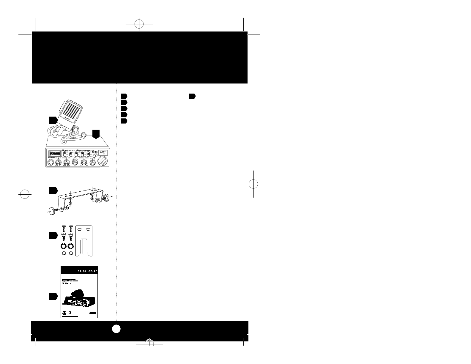
Included Accessories
What’s Included with Your GR 29 LTD ST
1. CB transceiver 6. DC power cord
2. Microphone (not shown)
3. Transceiver bracket
2
1
3
4. Microphone bracket
5. Operating Manual
4
5
A1
29 GR-English.qx 6/22/99 9:15 AM Page 39
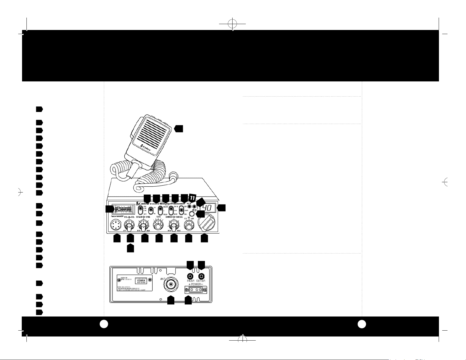
Controls and Indicators
1. 6 - Pin Mi c ro p h o n e
Co n n e cto r
2. Power On/Off,Volume
3. Squelch
4. RF Gain/ Dynamike
5. Tone
6. Dimmer/SWR CAL
7. Band Selector
8. Channel Selector
9. LED Channel Display
1 0 . Sound Tracker™ LED
11 . RX (Receive)/ TX (Transmit)
LED Indicator
12 . Sound Tracker™ On/Off
13 . S/RF SWR CAL Switch
14 . Channel 19/Channel 9/
Normal Switch
1 5 . Delta-Tune
16 . CB/PA Switch
17 . NB/ANL ANL Off Switch
1 8 . Signal Strength Meter
1 9 . Microphone
1 8
1
1 9
1 3
1 7
1 6
1 41 5
1 0
1 2
2 4 536 7 8
2 0 2 1
Our Thanks to You
Thank you for purchasing the Cobra GR 29 LTD ST
CB Radio.Properly used,this Cobra product will
give you many years of reliable service.
SoundTracker
TM
“Cuts noise coming in...strengthens signals
going out.”
This Patent-pending technology dramatically
improves transmission and reception of CB
signals.
The revolutionary SoundTrackerTMSystem reconfigures the transmission signal,allowing it to be
transferred more efficiently through cluttered
airwaves.
9
At the same time,it significantly reduces the
amount of static on all incoming CB signals.
The end result is a cleaner,clearer reception of
signals and a more powerful transmission which
dramatically improves CB communications.
Cobra on the World Wide Web:
Frequently Asked Questions
(FAQ) can be found on-line at:
www.cobraelec.com
Rear Panel
2 0 . Public Address Speaker
Jack
2 1 . External Speaker Jack
2 2 . Antenna Connector
2 3 . Power Jack
A2
2 2 2 3
A3
29 GR-English.qx 6/22/99 9:14 AM Page 1
How to Use Your
Contents
Section A(English)
Features..................................................................................................1
Included Accessories ......................................................................A1
Controls & Indicators.......................................................................A2
Our Thanks toYou.............................................................................A3
SoundTracker
Installation
Location.............................................................................................2
Mounting and Connection.........................................................2
Antennas
CB Antenna.......................................................................................6
Marine Installation.........................................................................6
Ignition Noise Interference ..........................................................7
Operating Your GR 29 LTD ST
Turning On Your CB........................................................................8
Setting Channel Selector.............................................................9
Calibrating For SWR (Standing Wave Ratio)..........................10
To Receive..........................................................................................12
Selecting a Channel.......................................................................13
S-Meter...............................................................................................13
SoundTracker™System................................................................14
Activating SoundTracker™..........................................................15
NB-ANL/ANL/Off (Noise Blanker/Automatic.........................16
Noise Limiter Switch)
Bright/Dim Switch..........................................................................17
RF Gain Control................................................................................17
Setting Delta Control....................................................................18
Setting Squelch...............................................................................18
ToTransmit........................................................................................20
Setting Dynamike...........................................................................20
Transmit..............................................................................................21
RF Meter.............................................................................................22
External Speaker.............................................................................23
PA (Public Address)........................................................................24
Home And Office Set-Up .............................................................26
Temporary Mobile Set-Up...........................................................27
HowYour CB Can Serve You..........................................................28
A Few Rules You Should Know..................................................28
Local Laws or Regulations...........................................................29
CB 10-Codes.....................................................................................30
Frequency Ranges.............................................................................32
GR 29 LTD ST Specifications.........................................................33
Accessories...........................................................................................34
Deutsch................................................................................Abschnitt B
Español.....................................................................................Sección C
Français....................................................................................Section D
Italiano .....................................................................................Sezione E
™
Cobra GR 29 LTD ST
Features of This Product
• 2.75-metre microphone cord
• 40 European CEPT
40 German FM
12 AM Channels
• SoundTracker™System
• Heavy-Duty Dynamic
Microphone With Channel
Changer
• Full 4 Watts FM RF Power Ou t p u t
• 1 Watt AM Power Ou t p u t
• SWR Calibration Meter
• Instant Channel 19 and 9
• Front Panel 6-Pin Microphone
Connector
• Switchable Automatic Noise
Limiter & Noise Blanker
• Tactile Controls
• Tone Control
• Illuminated Front Panel
• Dim Control
CAUTION
RISK OF ELECTRIC SHOCK
DO NOT OPEN
CAUTION: TO REDUCE THE RISK OF ELECTRIC
SHOCK DO NOT REMOVE COVER (OR BACK)
NO USER SERVICEABLE PARTS INSIDE
REFER SERVICING TO QUALIFIED SERVICE
P E R S O N N E L
!
!
1
29 GR-English.qx 6/22/99 9:14 AM Page 2
InstallationInstallation
Location
Mounting and
Connection
Note
The transceiver is held in the
universal mounting bracket by
two thumbscrews which allow
for adjustment at a convenient
angle.
The bracket includes two selftapping screws and star washers.The mounting must be
mechanically strong and conveniently located.
Location
Plan location of transceiver and microphone
bracket before starting the installation.
Select a location that is convenient for operation,
yet does not inte rfe re with the dri ver or passenger.
The transceiver is usually mounted to the underside of the dash with the microphone bracket
beside it.
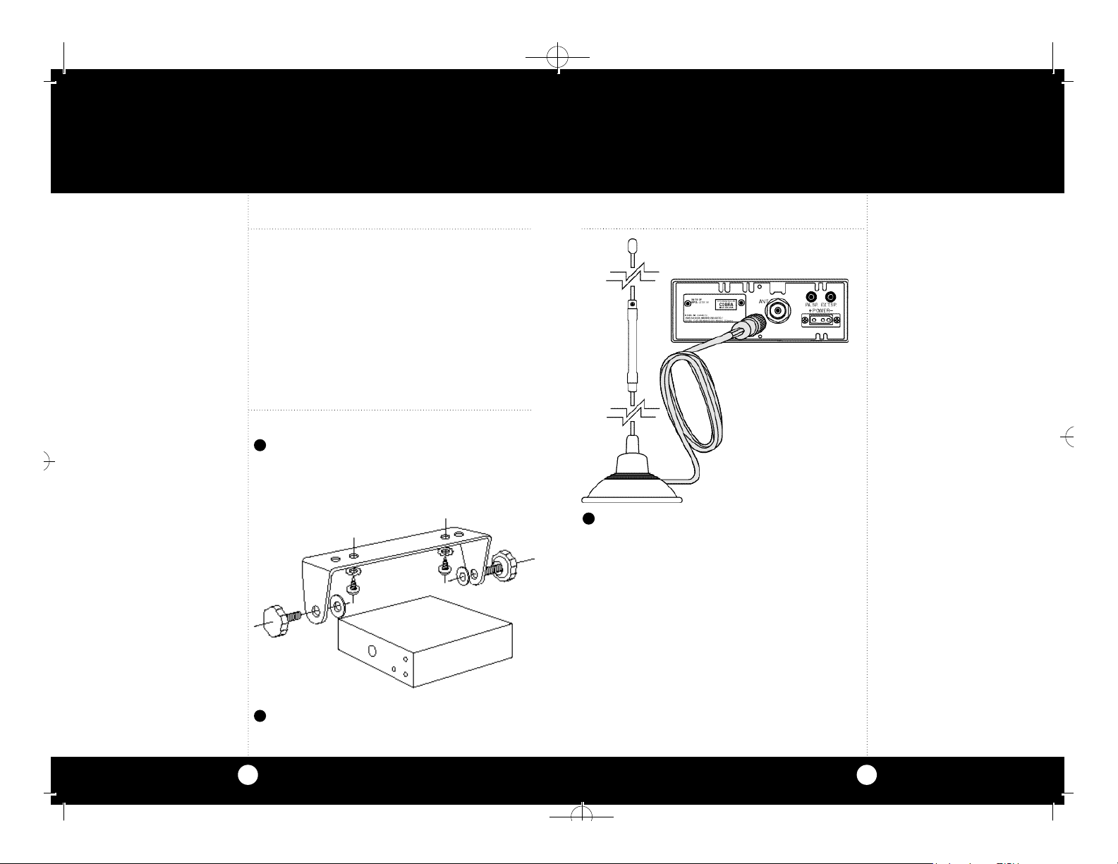
Mounting and Connection
1
Hold the radio with the mounting bracket in
the exact desired location.If there is no interference,remove the bracket and use it as a
template to mark the location for the mounting screws.
cb transceiver
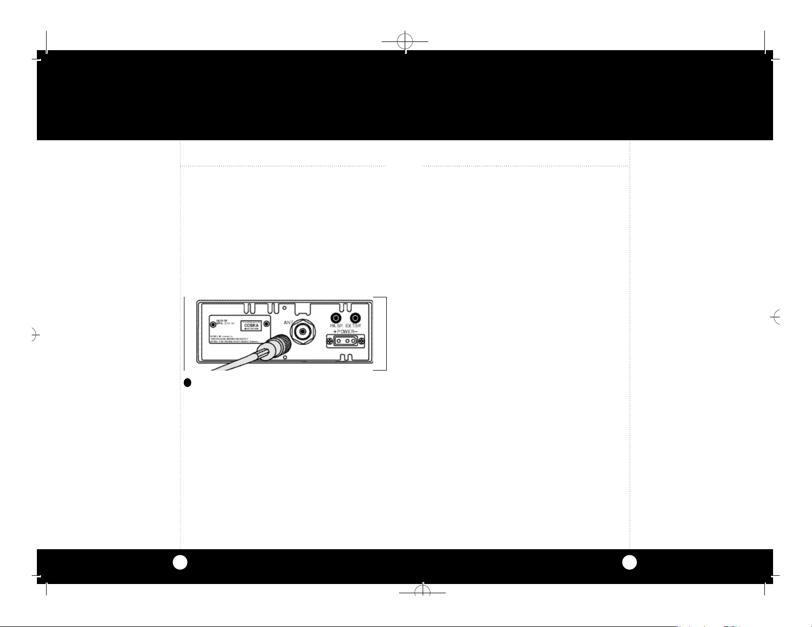
3
Connect the antenna cable plug to the receptacle marked “ANT” on the back of the unit.
2
Drill the holes and secure the bracket.
continued
32
29 GR-English.qx 6/22/99 9:14 AM Page 4
Note
Before installing the CB radio,
visually check the vehicle’s
battery connection to determine which terminal, positive
or negative,is earthed to the
engine block (or chassis). A
negatively earthed vehicle
has its negative lead earthed
to the chassis.
Note
Connecting to a fuse circuit controlled by the ignition switch
prevents the unit from being left
on accidentally,and also permits operating the unit without
running the engine.
Note
In positive earth vehicles the red
wire goes to the chassis and the
black wire is connected to the
ignition switch.
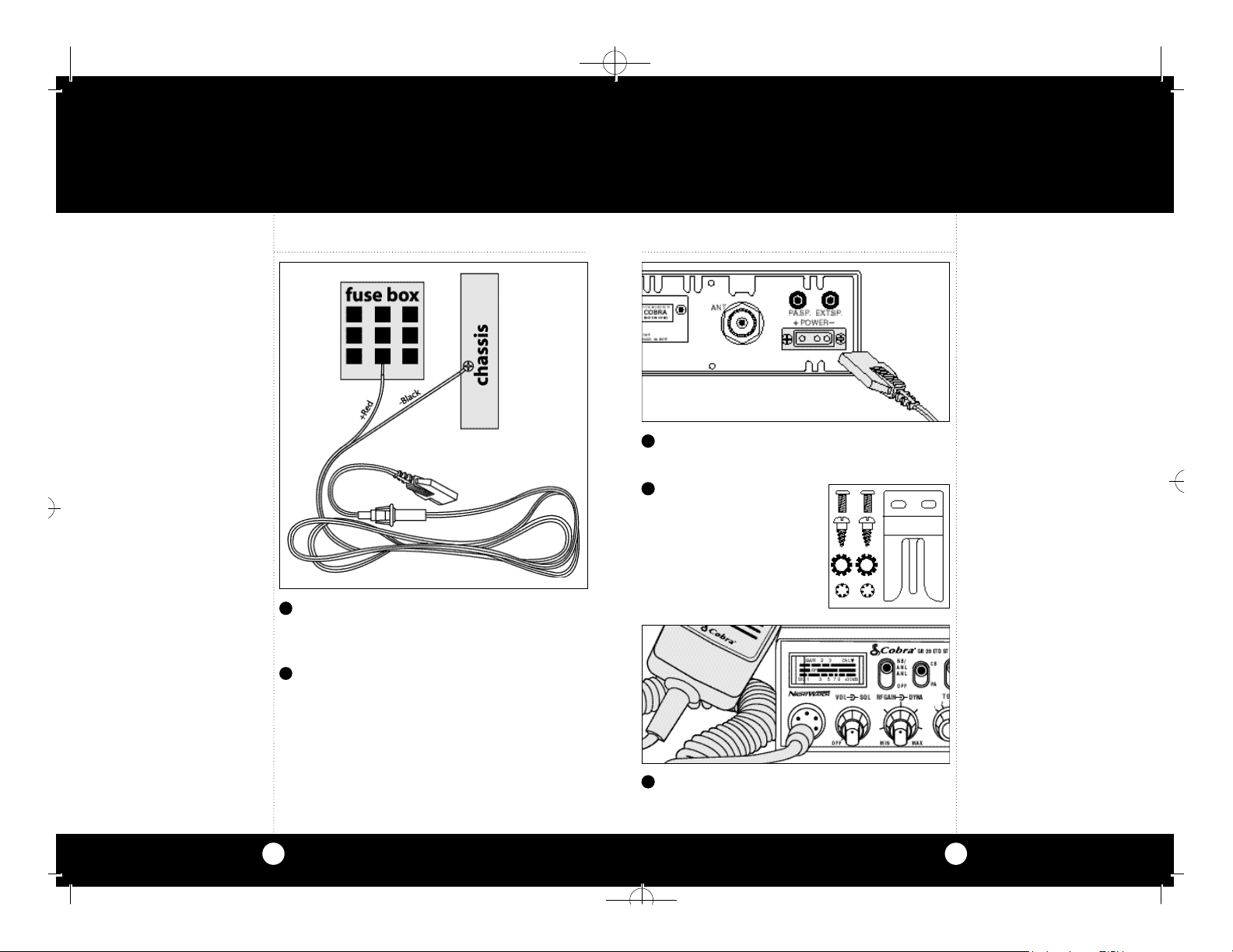
4
In a negative earthed vehicle,connect the red
lead of the DC power cord to an accessory 12
volt fuse.
5
Connect the black lead to the negative side of
the vehicle.This is usually the chassis.Any convenient location with a good electrical contact
(remove paint) may be used.
6
Plug power cable into back of unit marked
“Power”. Be sure to observe polarity markings.
7
Mount the microphone
bracket on either side of
the unit (nearer the driver)
using two screws supplied.Bracket should be
placed under the dash
so that microphone is
readily accessible.
InstallationInstallation
8
Attach the 6-pin microphone cable to receptacle on front of unit and Install unit in bracket
securely.
54
29 GR-English.qx 6/22/99 9:14 AM Page 6
Ignition Noise InterferenceAntennas
CB Antenna
Note
For optimum performance in
passenger cars the ideal antenna location is on the centre of
the roof.Second choice is on the
centre of the boot.
Note
Antenna must be earthed to the
chassis of the vehicle.
CB Antenna
The antenna is critical in affecting transmission
distance.Only a properly matched antenna system will allow maximum power output. Cobra
loaded type antenna models are highly recommended for most installations.Consult your
Cobra dealer for further details.
1
A standard antenna connector is provided
on the transceiver for easy connection.
Marine Installation
The transceiver will not operate at maximum efficiency in a boat without an earth plate,(unless it
has a steel hull).Before attempting installation ,
consult your dealer for information regarding an
adequate earthing system and prevention of
electrolysis between fittings in the hull and water.
Use of a mobile receiver at low signal levels is
normally limited by the presence of electrical
noise.The primary source of noise in cars is from
the alternator and the ignition system.Typically,
when signal level is adequate,the background
noise does not present a serious problem.Also,
when extremely low-level signals are being
received,the transceiver may be operated with
the vehicle’s engine turned off.The unit requires
very little current and therefore will not significantly discharge the vehicle’s battery.
Even though the Cobra GR 29 LTD ST has an automatic noise limiter,in some installations ignition
interference may be high enough to make good
communications impossible.Many possibilities
exist and variations between vehicles require
different solutions.Consult your COBRA dealer or
a 2-way radio technician for help in locating the
source of a severe noise.
6
7
 Loading...