

Cobolt MLD 445 nm, MLD 405 nm, DPL 553 nm, DPL 561 nm, MLD 638 nm Owner's Manual
...
OWNERS MANUAL | Cobolt Skyra™ | D0423-E JANUARY 2018
Multi-line Laser
405 nm
515 nm
633 nm
445 nm
532 nm
638 nm
473 nm
553 nm
647 nm
488 nm
561 nm
660 nm
Cobolt Skyra™

OWNERS MANUAL | Cobolt Skyra™ | D0423-E JANUARY 2018
2 | 45
CONTENTS
Introduction 4
Safety 5
General 5
Fiber Coupled Option 6
Accessible emission information for Cobolt Skyra™ laser lines 6
Safety features 7
Warning and Identification Labels 8
Equipment Safety 9
Constant Power Quick Start 10
Cobolt Monitor™ Software 11
Installation 11
Software instructions 11
Modulation Quick start 15
Settings 15
Laser 1 : DPL Modulation Inputs 16
Laser 2, 3 and 4 : MLD Modulation inputs 17
Closedown operation 17
System Overview 18
Model number 18
Configuration 19
Laser head 20
Key control box 20
Thermal management 21
Power supply requirements 21
System Description 22
Specification 22
Mechanical Drawings 25
Remote Interlock Connector 27
Direct On/Off control 27
Pin assignment 28
Continuous wave operation 30
Modulation mode operation 30
Digital modulation 30
Analog modulation 31
Internal modulation 32
Modulation mode combinations 32
Settings Optimization in modulation mode 33
Operation via data port 34
Handshaking 34
RS232 configured controllers 34
USB driver 34
Communication commands 37
Troubleshooting 41
Warranty and Maintenance 43

OWNERS MANUAL | Cobolt Skyra™ | D0423-E JANUARY 2018
3 | 45
Service 43
Disclaimer 43
Compliance (CDRH models only) 44

OWNERS MANUAL | Cobolt Skyra™ | D0423-E JANUARY 2018
4 | 45
Introduction
Cobolt SkyraTM is an extremely compact, permanently aligned, plug & play, multi-line laser with up to 4 laser
lines and control electronics integrated into one single, temperature-controlled package, small enough to fit in
the palm of your hand!.
The laser is built using Cobolt’s proprietary HTCure™ manufacturing technology for robustness in a compact,
hermetically sealed package. HTCure™ results in an ultra-stable, permanent alignment of optical elements,
with very precise and stable overlap of the combined output beams.
The Cobolt SkyraTM is intended for stand-alone use in laboratory environments or for integration as OEM
components in instruments for applications including fluorescence microscopy and flow cytometry.

OWNERS MANUAL | Cobolt Skyra™ | D0423-E JANUARY 2018
5 | 45
Safety
General
The laser classification of Cobolt Skyra™ is dependent on the specific laser lines present a multi-line laser. The
wavelengths and maximum accessible emission can be found on the warning label on the laser head. See section 2.1
for detailed information on warning and identification labels.
The sum of the maximum emitted power of all laser lines in the multi-line laser determines the laser classification.
The residual emission at wavelengths outside the specified range do not exceed Laser Class 1. A multi-line laser
capable of emitting less than 500 mW of laser radiation within the visible spectrum (405 nm – 660 nm) is Class IIIB
(CDRH), Class 3B (IEC).
A multi-line laser capable of emitting more than 500 mW of laser radiation within the visible spectrum (405 nm – 660
nm) is Class IV (CDRH), Class 4 (IEC).
Eye and skin exposure to direct or reflected laser light is hazardous and may be extremely harmful. Always wear eye
protection appropriate to the beam wavelength(s) and intensity and never look directly into a laser beam. Laser
radiation may ignite flammable materials and combustible gasses in the beam path and, in event of ignition, fumes
may be generated. All equipment used in close proximity to the laser beam should be suitably fire resistant and the
facility should be properly ventilated. It is advised to perform a risk assessment for the facility and equipment prior to
using the laser. In the case of integration into a larger system, laser safety compliance must be evaluated in the end
product. The device must be handled by skilled personnel experienced with lasers, in a laboratory environment and
with access to adequate laser safety equipment. The laser head clearly displays a yellow warning label that shows the
location of the laser beam aperture. This label must be visible unless the laser beam is totally enclosed. If the laser
does not function, do not attempt to open any of the units, or the warranty will be voided. Call or e-mail your local
Cobolt representative for consultancy and to request an RMA number (see back cover for contact information).
CAUTION Use of controls or adjustments or performance of any procedures other than those
specified herein may result in exposure to hazardous radiation.
OWNERS MANUAL | Cobolt Skyra™ | D0423-E JANUARY 2018
6 | 45
Fiber Coupled Option
All safety recommendations in section 2 are also valid for the Cobolt Skyra™ fiber coupled laser heads. Additionally,
heat generated from absorption of laser radiation by particles on the fiber end may increase the probability of ignition
hazards in certain environments. Always clean the fiber end before turning on the laser. In systems where the beam
is exposed, fiber end must be mounted < 2 m from the emission warning LED. It is advised to perform a risk
assessment for the facility and equipment prior to using the laser. In the case of integration into a larger system, laser
safety compliance must be evaluated in the end product.
Accessible emission information for Cobolt Skyra™ laser lines
The table below describes the irradiance in W/cm2 and appropriate level of eye protection in terms of optical density
(OD) for each product line. Using a multi-line laser requires a combination of eye protection that is specifically tailored
to the device configuration. Be sure to consider all available wavelengths and power levels when selecting eye
protection.
Laser line
Nominal Output Power
(mW)
Max Power
(mW)
Max Irradiance
(W/cm2)*
Eye protection Requirement
(OD)**
Cobolt MLD 405 nm
50
120
50
4
100
120
50
4
Cobolt MLD 445 nm
50
120
42
4
Cobolt MLD 473 nm
50
120
42
4
Cobolt MLD 488 nm
50
80
28
3
Cobolt MLD 515 nm
50
100
35
3
Cobolt DPL 532 nm
50
100
150
300
53
106 3 3
Cobolt DPL 553 nm
50
100
32
3
Cobolt DPL 561 nm
50
150
48
3
Cobolt MLD 633 nm
50
100
35
3
Cobolt MLD 638 nm
50
120
71
3
Cobolt MLD 647 nm
50
150
53
3
Cobolt MLD 660 nm
50
130
46
3
* Irradiance (W/cm2) = Max Power (W) Beam Area at bottom tolerance (cm2)
** Eye protection (OD) = Log10( Max Power (W) 60825-1 Emission Limit : Class 1 (W) ) , rounded up to the next integer.
CAUTION Always wear the appropriate eye protection for all of the specified emitted wavelengths.
Verify the accessible emission wavelengths and power levels on the warning label before operating.

OWNERS MANUAL | Cobolt Skyra™ | D0423-E JANUARY 2018
7 | 45
Safety features
The laser is equipped with all required safety features as described in the laser safety standard IEC 60825-1. If any part
of the delivered equipment is replaced with a part not supplied by Cobolt or if the equipment is not properly grounded
the device may not conform to CE / CDRH compliance standards listed in section 15. Disabling any of the safety
features nullifies the CE marking and violates the laser safety standard.
Remote Interlock Connector
The remote interlock connector is a connector which permits the connection of external controls placed apart from
other components of the laser product. When the terminals of the connector are open-circuited, emission is
interrupted and no radiation will be accessible. The remote interlock connector permits easy addition of an external
interlock in laser installation. See section 7.3 for a detailed description of the remote interlock circuit and operation.
Manual Shutter (Beam Stop)
The laser head is equipped with a manual shutter, which functions as the beam stop, capable of preventing human
access to laser radiation. In the case of the fiber coupled front the screw on cap functions as the shutter. The aperture
location and the open and close positions of the shutter are indicated on the top surface of the laser head.
Key Control
The CDRH compliant model comes with a key control box which must be connected for the laser to operate. When
the key is in the OFF position, the diodes are prevented from emitting. The key must be actively turned to the ON
position each time the laser is powered on. When the key is removed from the key control box, laser radiation is not
accessible.
Laser Radiation Emission Warning
The key control box, which is part of the CDRH compliant models, incorporates LEDs which indicate the status of the
Laser. The “ON” LED is illuminated whenever the device is emitting or could emit light. See section 6.4 for details on
the key control box. The emission warning indicators are also visible in the Cobolt Monitor™ software, see section 4 :
Cobolt Monitor™ Software for details on the control software.

OWNERS MANUAL | Cobolt Skyra™ | D0423-E JANUARY 2018
8 | 45
Warning and Identification Labels
The upper face of the laser head contains a yellow label with laser safety warning and classification information, the
wavelength and maximum power of the unit. It also shows the location of the laser beam aperture and indicates the
open and closed positions of the manual shutter. This label must be visible unless the laser beam is totally enclosed.
A silver label showing information about the laser model, manufacturer date and location, and the power supply
voltage and current, is located on the laser head. Lasers shipped to customers in the USA also contain a label of CDRH
compliance.
Laser Notice No. 50 Label
CDRH models shipped to USA
CE /CDRH compliant label
OEM label
Aperture Warning Labels
Manufacturer Identification Labels

OWNERS MANUAL | Cobolt Skyra™ | D0423-E JANUARY 2018
9 | 45
Equipment Safety
Back Reflection Sensitivity
Laser light reflected directly back into the laser head causes damage to the laser diode and results in a dramatic
decrease in product lifetime. The MLD lasers with a wavelength greater than 600 nm are particularly sensitive to back
reflections; exercise extreme caution.
Electrostatic discharge
Always install the laser power supply to a properly grounded power outlet. Cobolt lasers contain a laser diode which
is sensitive to electrostatic discharge (ESD).
Fiber care
It is important to always make sure the fiber end-face is clean before turning the laser on and before connecting the
fiber connector in physical contact with another connector. Failure to do so may lead to irreparable damage of the
fiber end-face. Do not clean the fiber when the laser is on. We recommend using appropriate equipment for fiber
cleaning and inspection.
OWNERS MANUAL | Cobolt Skyra™ | D0423-E JANUARY 2018
10 | 45
Constant Power Quick Start
1. Mount the laser on a heat sink or suitable flat surface that provides adequate heat dissipation and connection
to ground. Use the four holes on the laser’s base plate to secure it.
(HS-05 : https://www.coboltlasers.com/lasers/options-accessories/ )
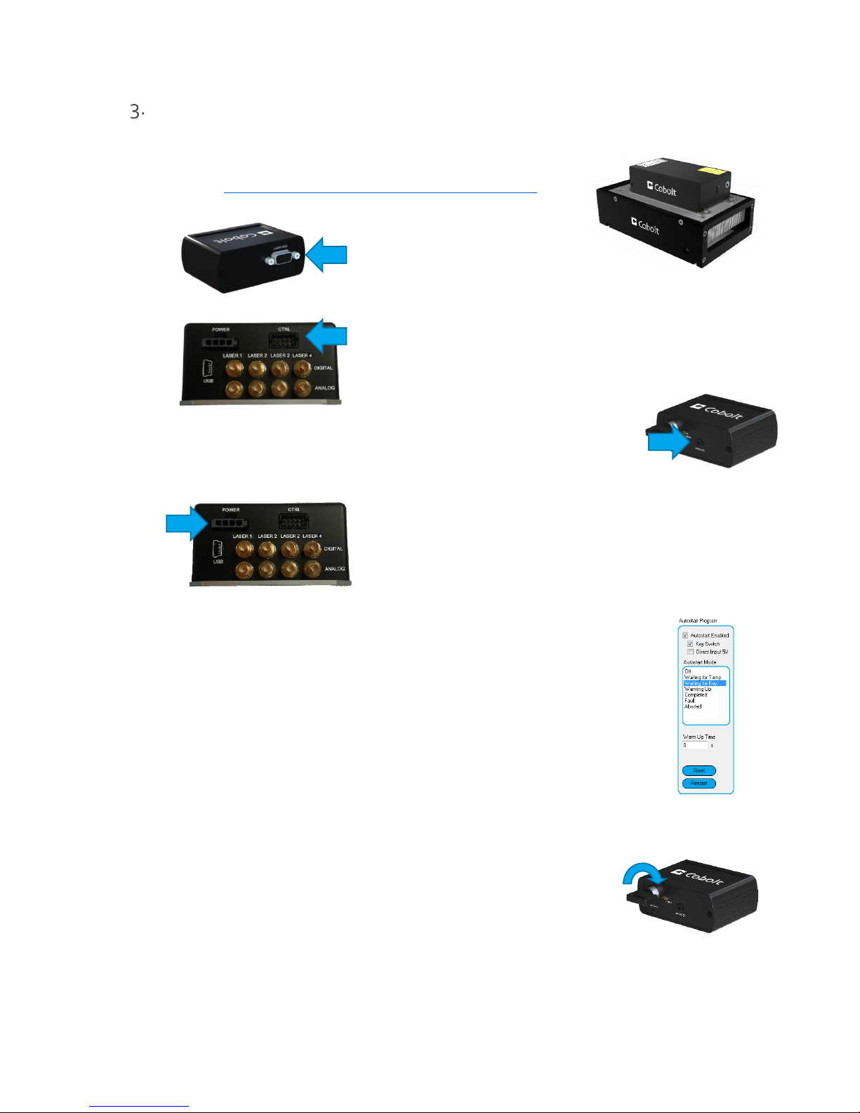
2. Attach the 15-pin D-SUB cable to the Control Box.
3. Attach the 10 pin Molex connector to the laser head.
4. Insert the interlock plug into the connector on the key control box.
5. Connect the supplied 12V power supply unit to the socket on the laser head, and plug it in to the mains.
The laser will go through the auto start sequence:
Waiting for Temp
Laser emission is not enabled until all temperatures have
reached their set point and the TECs are stabilized.
Waiting for Key
Toggle the key to proceed, if the key is already in the ON
position, turn of OFF and ON again.
Warm up
A low current is provided to warm the laser before setting
full power
Completed
The device is emitting or armed for emission.
6. To start the laser, turn the key on the key control Box clockwise to the ON position. If it is already in the ON
position, turn it to OFF and then ON again. At delivery all laser lines are ‘ACTIVE’ and ‘ON’, laser light will be
emitted as soon as the key is turned.
7. All laser lines will now start up in continuous-wave, constant power mode at the nominal power level. The
power and wavelength may continue to drift slightly for up to 3 minutes while the thermoelectric cooler (TEC)
stabilizes.
OWNERS MANUAL | Cobolt Skyra™ | D0423-E JANUARY 2018
11 | 45
Cobolt Monitor™ Software
The Cobolt Monitor™ software provides a graphical way to monitor the laser performance and to change the
output power, operation mode and other settings. Cobolt Skyra™ is compatible with Cobolt Monitor™ 6.0.7.0
and later.
Cobolt Monitor™ has been tested with operating systems Windows XP, Windows Vista, Windows 7, Windows 8
and Windows 10. Microsoft .NET 4.0 is required to run the Cobolt Monitor™ software. Most computers with
operating systems Windows XP, Windows Vista, Windows 7 and Windows 8 have this included as standard.
When using versions of Windows older than Windows 10, a USB driver may be required. See Section 10.2 : USB
driver for details on installation.
Installation
Download the latest version of the Cobolt Monitor™ software from www.coboltlasers.com. The Cobolt Monitor™
software is a stand-alone executable. The executable file is packaged with other files needed to run the program in a
.zip file. Save the .zip file to any storage device, and extract all files. The folder created after extracting the files can
be placed on any storage device and Cobolt Monitor™ can be run from there. All files and folders contained in the .zip
file must be present for the program to function properly.
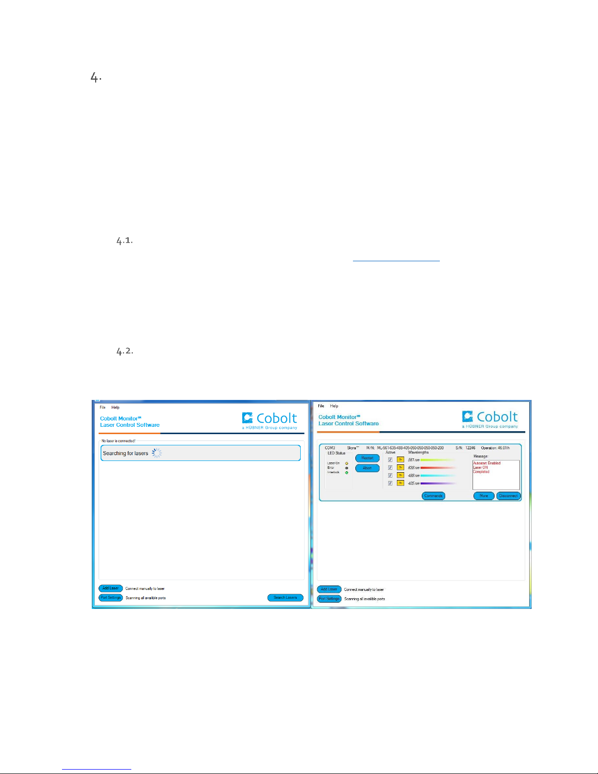
Software instructions
The software automatically searches for Cobolt devices and automatically connects the laser if detected. The
software can identify USB connected lasers as well as RS232 connected lasers.
The first Cobolt Monitor™ window that appears in the software.
Once the laser is connected it can be controlled from Cobolt Monitor™ software. Only the most critical information
is displayed on this level, including the status the laser is in and the possibility to switch each line ON or OFF. Here
follows a short description of how to use the Cobolt Monitor™ software on this level.
OWNERS MANUAL | Cobolt Skyra™ | D0423-E JANUARY 2018
12 | 45
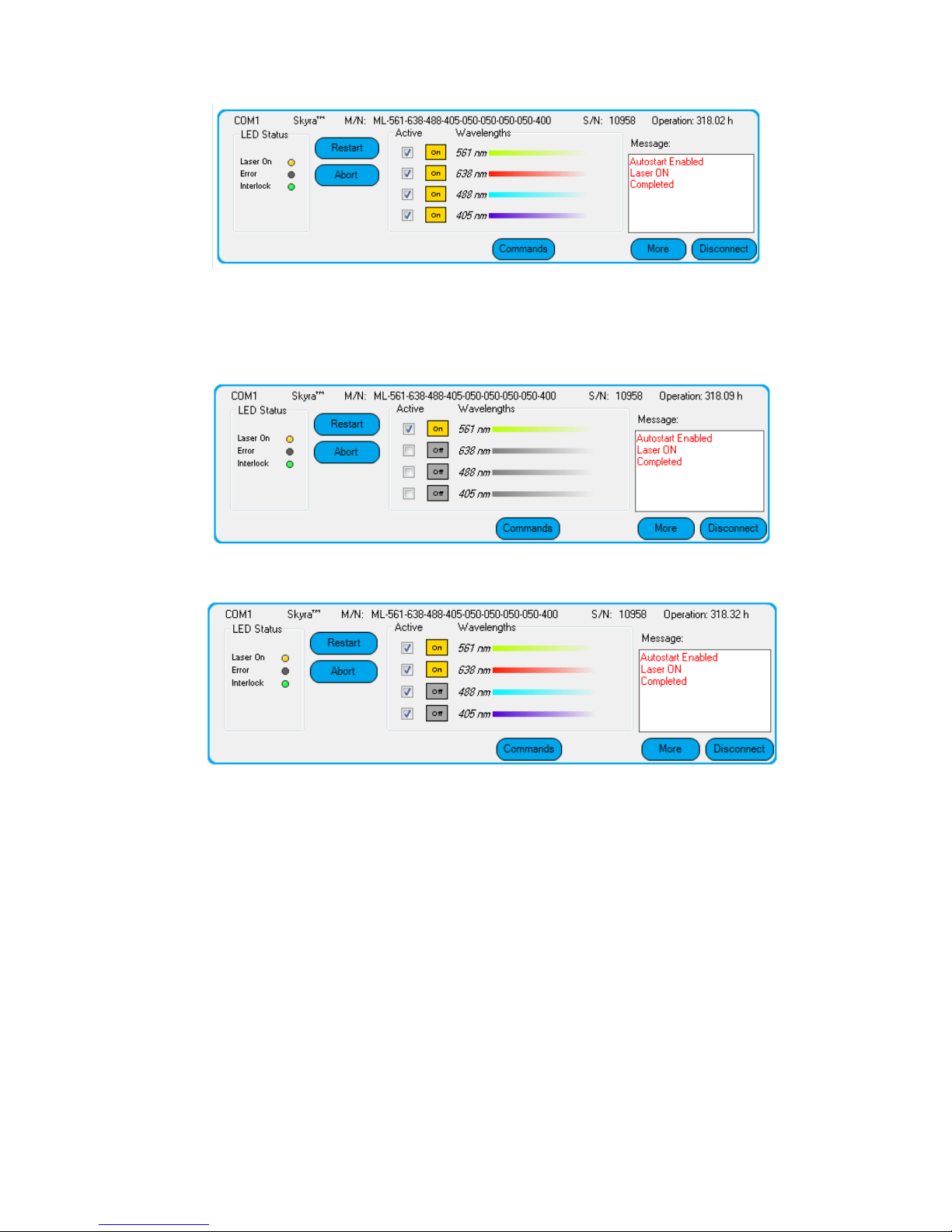
Restart Turns all active lasers ON by re-starting the autostart sequence.
Abort Turns all lasers OFF.
Active Check the box to choose the lasers that are active in the autostart sequence.
ON/OFF Use these buttons to toggle the individual laser lines ON and OFF after the autostart sequence has
been completed.
Commands Opens a command communications window to send commands directly to the laser. See section
10.3 : Communication commands for more details on available commands.
Message Highlights important information about the laser status to the user.
Disconnect Allows the user to disconnect from the Cobolt Monitor™ software in a controlled way.
NOTE The communication cable should not be removed when the software is in connect state. To
disconnect the laser click “Disconnect” or close Cobolt Monitor™ completely. It is also possible to disconnect
by powering the laser OFF. In this case Cobolt Monitor™ will automatically close the window for that laser.
More An additional Cobolt Monitor™ window will open containing more detailed information of that
laser’s status.
!
OWNERS MANUAL | Cobolt Skyra™ | D0423-E JANUARY 2018
13 | 45
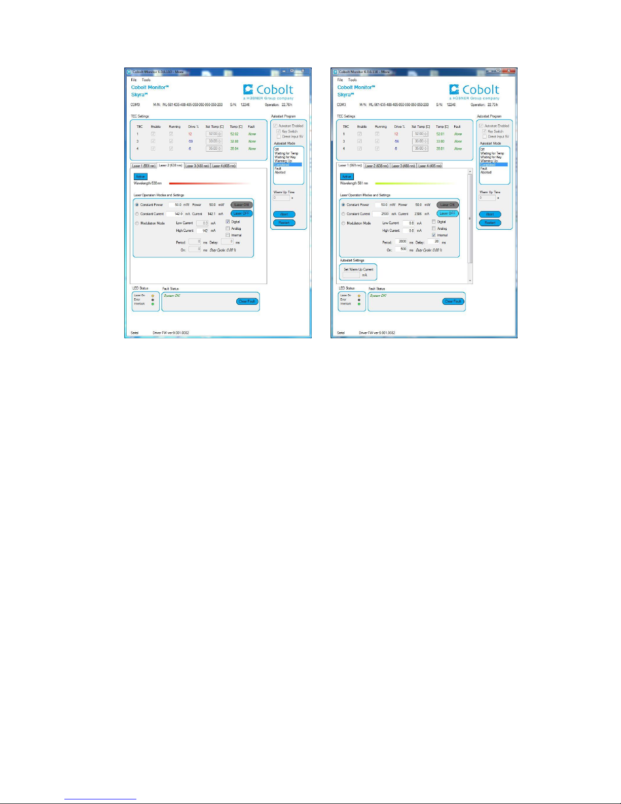
Cobolt Monitor™ software expanded to for more detailed monitoring.
TEC Settings Shows the running status and the fault status for the laser’s internal thermoelectric coolers (TEC).
Laser Operation Mode and Settings
Displays the set laser power. The user can switch between constant power mode, constant current
mode and modulation mode. Likewise, there are boxes to set the constant power level and constant
current level. In constant power mode the current will be set by Cobolt Monitor to reach the power
level set in the this field. When in modulation mode it is recommended to use an external power
meter, the internal measurement will not be reliable. See section 8 and 9 for more details on
continuous wave and modulation modes. Use the tabs to go from laser to laser.
Autostart Program
Displays whether the laser is in CDRH or OEM mode and displays the current laser operational
status. There are also buttons to “abort” the autostart sequence or to “restart” the laser after a fault.
Waiting for Temp
Laser emission is not enabled until all temperatures have reached their set point and
the TECs are stabilized.
Waiting for Key
Toggle the key to proceed, if the key is in the ON position, turn of OFF and ON again.
Warm up
A current is provided to warm the laser before setting full power
Completed
The device is emitting or armed for emission.
Fault
The device has a fault, the fault status must be cleared before the laser can be
restarted.
Aborted
The autostart sequence has been aborted, but the TECs are still running.

OWNERS MANUAL | Cobolt Skyra™ | D0423-E JANUARY 2018
14 | 45
Fault Status Displays ERROR messages. In the event of an ERROR, the laser action is stopped. When the reason
for the ERROR event is understood and the problem is addressed the fault status can be cleared with
“Clear Fault”. If the Autostart Program is enabled, click restart to restart the laser.
LED Status Displays the LEDs that are currently illuminated on the key control box, see section 6.4.These are
displayed even if the laser is in OEM mode.
Laser ON
Green
The laser is emitting or armed for emission.
ERROR
Red
An error has occurred.
INTERLOCK
Green
Red
The interlock is in place.
The interlock is open.
 Loading...