

cobia 217cc Owner's Manual
May 30, 2012
COBIA 217 CC
O w n e r ’ s M a n u a l
WELCOME
Dear New Cobia Owner,
On behalf of Cobia Boats, I would like to congratulate
you on your purchase. We at Cobia strive to build the
best products possible and wish you years of trouble
free enjoyment. There are many things to know about
the operation, care and maintenance of our products
and the systems we install in them. Please review all
the applicable information for your new boat. The more
you know, the more you will enjoy your new Cobia.
Again, a heartfelt Thank You from myself and the whole
Cobia Family.
Scott Deal, President and CEO
Maverick Boat Company, Inc. • 3207 Industrial 29th St. • Fort Pierce,
Florida 34946 • (772)-465-0631 or (888)-shallow • Fax: (772) 489-2168
May 30, 2012
TABLE OF CONTENTS
Yamaha Engine Break-In Periods...........................................3
Engine Stop Switch.................................................................3
Fuel / Water Separators..........................................................4
Garboard Drain Plug...............................................................4
Instrument Panel with Yamaha Multi-Function
Gauges....................................................................................5
Switch Panels..........................................................................5
Switch Panels & Helm.............................................................5
216 Boat Layout......................................................................6
Cobia Duffel Bag.....................................................................6
Bilge System...........................................................................7
Ball Valves, Thru Hull Fittings, & Scuppers.............................8
Stainless Boarding Ladder....................................................10
Cockpit Courtesy Lights..........................................................9
Props.....................................................................................10
Head & Waste System..........................................................19
Fuel System..........................................................................11
Self Bailing Cockpit...............................................................12
Livewell System....................................................................12
Optional Bow Cushion Set.................................................17
Dual Battery System..........................................................15
Optional Salt Water Washdown.........................................20
Optional Fresh Water Shower............................................18
Optional Trim Tabs.............................................................19
Optional Command Link Gauges.......................................18
Warranty.............................................................................24
217 SPECIFICATIONS
L.O.A.....................................................................21’ 7”
BEAM......................................................................8’ 6”
DRAFT......................................................................14”
WEIGHT W/O ENGINE......................................2950
LBS.
FUEL CAPACITY...........................................100 GAL.
DEADRISE @ TRANSOM.......................................20
DEG MAXIMUM
H.P.............................................................................200
TRANSOM HEIGHT……………………………..25”
MAXIMUM CAPACITIES…………………..…........8
PERSONS OR 1600 LBS
Rod Lockers..........................................................................13
Forward Storage...................................................................14
Anchor Locker / Rode Storage..............................................14
217 Aluminum Plate Location................................................14
Specifications..........................................................................2
Wiring Color Codes...............................................................16
Optional Cockpit Bolsters......................................................18
Maverick Boat Company, Inc. • 3207 Industrial 29th St. • Fort Pierce,
Florida 34946 • (772)-465-0631 or (888)-shallow • Fax: (772) 489-2168
May 30, 2012
ENGINE BREAK-IN PERIOD
Engine Break-In Period
New engines require a period of break-in to allow the
surfaces of the moving parts to mate evenly. Different
engines require different break-in periods and methods.
For instructions on break in methods, refer to your
Yamaha Engine Owner’s Manual for the correct break-in
procedures and times for your model engines
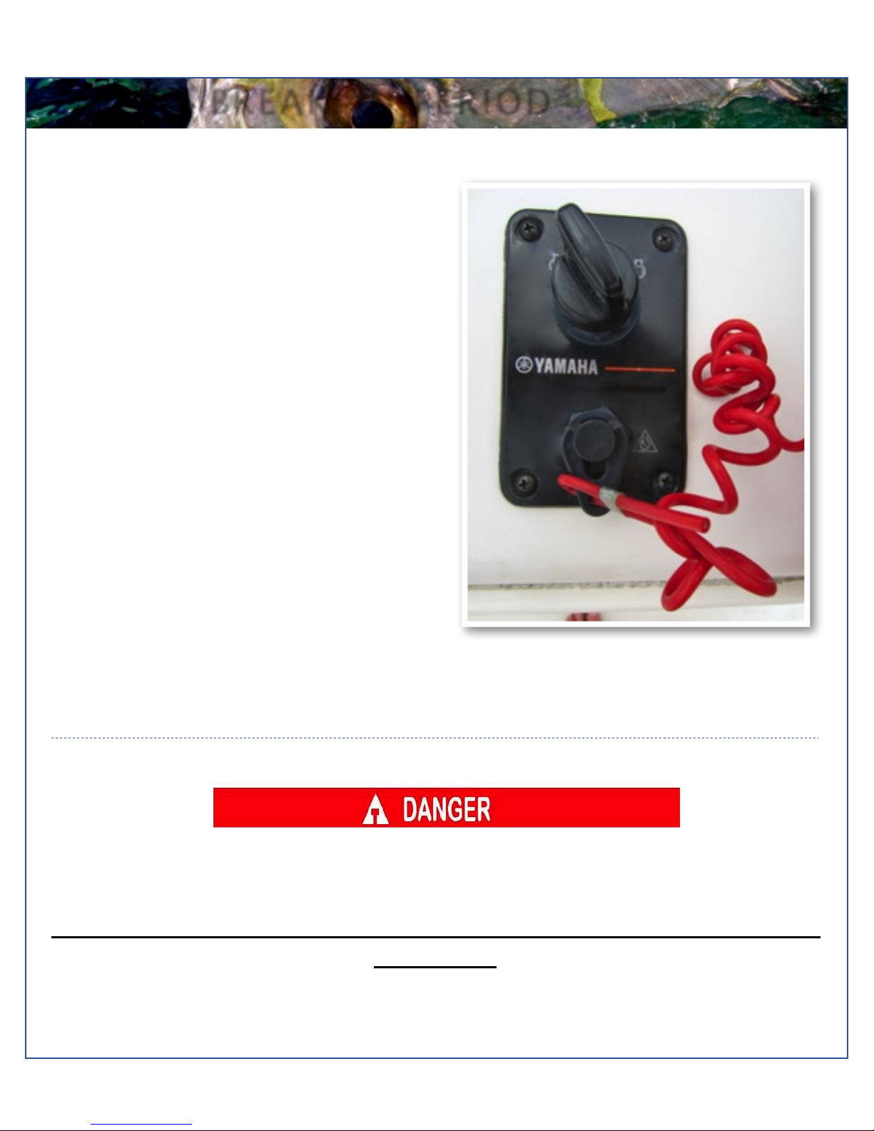
Engine Stop Switch
If activated, the spring loaded engine stop switch will
automatically shut down the engine during emergency
situations to prevent uncontrolled or unattended
operation. Certain emergency conditions (e.g., turbulent
water, wakes, accidental shove) may impair a person’s
ability to operate the craft safely. The switch, located on
the helm, must have the safety lanyard attached at its
base. This activates the protective shutdown circuitry.
Securely attach the other end of the lanyard to the
operator of the boat. If the operator moves, falls or is at
an unsafe distance from the steering wheel, tension on
the lanyard will pull it from the switch. When the lanyard is
removed, the engine stop switch is released and
automatic engine shutdown occurs.
Engine stop switch (above)
Engine Stop Switch
An engine stop switch system that is not used or does not function properly can cause death or serious injury.
DO NOT operate the boat if the engine stop switch system does not function properly. Go to a Cobia Dealer to
have this resolved immediately
The lanyard should be securely attached to the boat operator at all times that the
engine is on.
Maverick Boat Company, Inc. • 3207 Industrial 29th St. • Fort Pierce,
Florida 34946 • (772)-465-0631 or (888)-shallow • Fax: (772) 489-2168
May 30, 2012
FUEL-WATER SEPARATOR & DRAIN PLUG
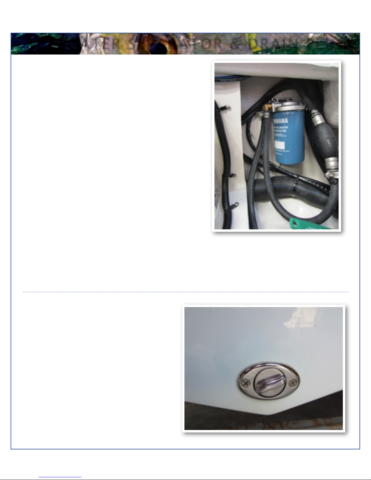
Fuel-Water Separator
A Yamaha Fuel - Water Separator is installed
between the fuel tank and engine on your 217
model. The new, improved 10-micron filter
provides superior filtration ahead of the engine's
on- board filters and injectors. Large filtering
and water capture areas maximize filtration
while maintaining adequate flow rate for larger
engines. The fuel separator can be checked by
removing it from the mounting bracket and
dumping it into an approved waste collection
device. If there appears to be an excessive
amount of water, the filter component should be
replaced. See your authorized Cobia Dealer for
replacement parts.
Maintenance Note
Yamaha recommends replacing the 10- micron fuel filter on new boats after the first 10 hours or 1 month of
operation and every 50 hours or every 6 months thereafter. In areas of hight humidity where water in fuel supplies is a
problem or extensive engine operation occurs, more frequent replacement may be necessary.
Garboard Drain Plug
The garboard drain plug is the small metal plug located at
the lowest point on the hull, at the bottom of the transom
right above the keel. The drain has been designed to so
that it can be loosened by hand while the hull is out of the
water for draining. This allows the plug to stay in contact
with the surrounding frame so you’ll never misplace or
lose it. You can completely remove the insert by pulling
back and continue turning in a counter clockwise motion.
It is manufactured with a rubber seal in place to ensure
you bilge is watertight. Always make sure before putting
the boat in the water that this plug is hand tightened
firmly. Excess water in the bilge may be an indication of a
problem with this plug or the automatic bilge pump. Refer
to page 7 of this Owner’s Manual for information on your
boats bilge system.
Maverick Boat Company, Inc. • 3207 Industrial 29th St. • Fort Pierce,
Florida 34946 • (772)-465-0631 or (888)-shallow • Fax: (772) 489-2168
May 30, 2012
SWITCH AND INSTRUMENT PANEL
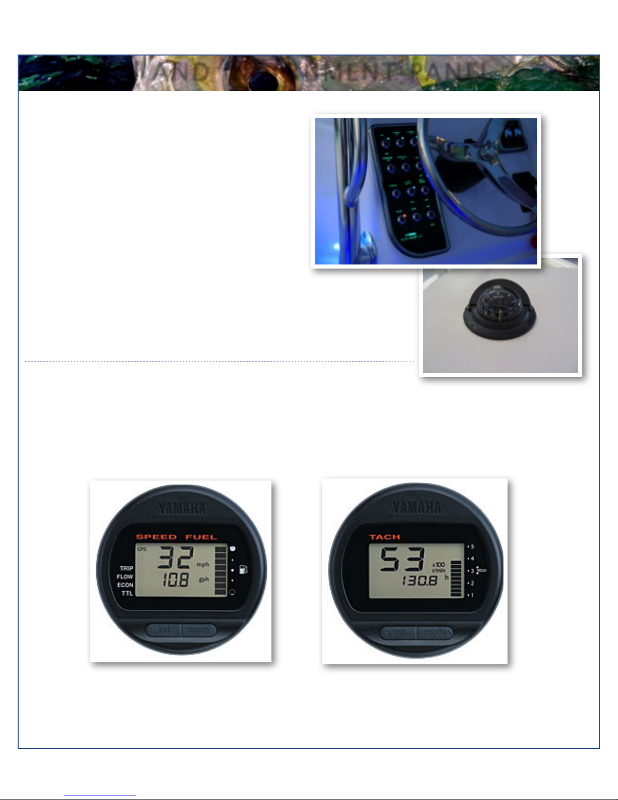
Switch Panel & Helm
At the helm of the 217 CC, you have a main switch
panel, which is located to the left of the steering
wheel. This panel controls your lights, horn,
accessories, livewell, and your bilge. When a
switch is in the “on” position, its tip is illuminated.
This alerts you that the associated accessory
should be functioning and also reminds you to turn
it off during boat shutdown. When the “NAV” light
switch is in the “on” position, the labels for the
switches will be illuminated. To the right of the
steering wheel you may have your two trim tab
switches, which are optional on the 217. (Refer to
page 23 for trim tab operation.) The 217 also
comes standard with a compass mounted on top
of the console.
Switch Panel
Compass
Instrument Panel
The instrument panel on your 217 CC is composed of two Yamaha Multifunction Digital Gauges. The standard
digital gauges include a tachometer. The tachometer has several built in features including an oil level monitor,
an engine temperature monitor and engine trim indicator. Yamaha speedometer includes a digital readout of the
speed, an hour meter, trip meter, and clock.
Maverick Boat Company, Inc. • 3207 Industrial 29th St. • Fort Pierce,
Florida 34946 • (772)-465-0631 or (888)-shallow • Fax: (772) 489-2168
May 30, 2012
BOAT LAYOUT
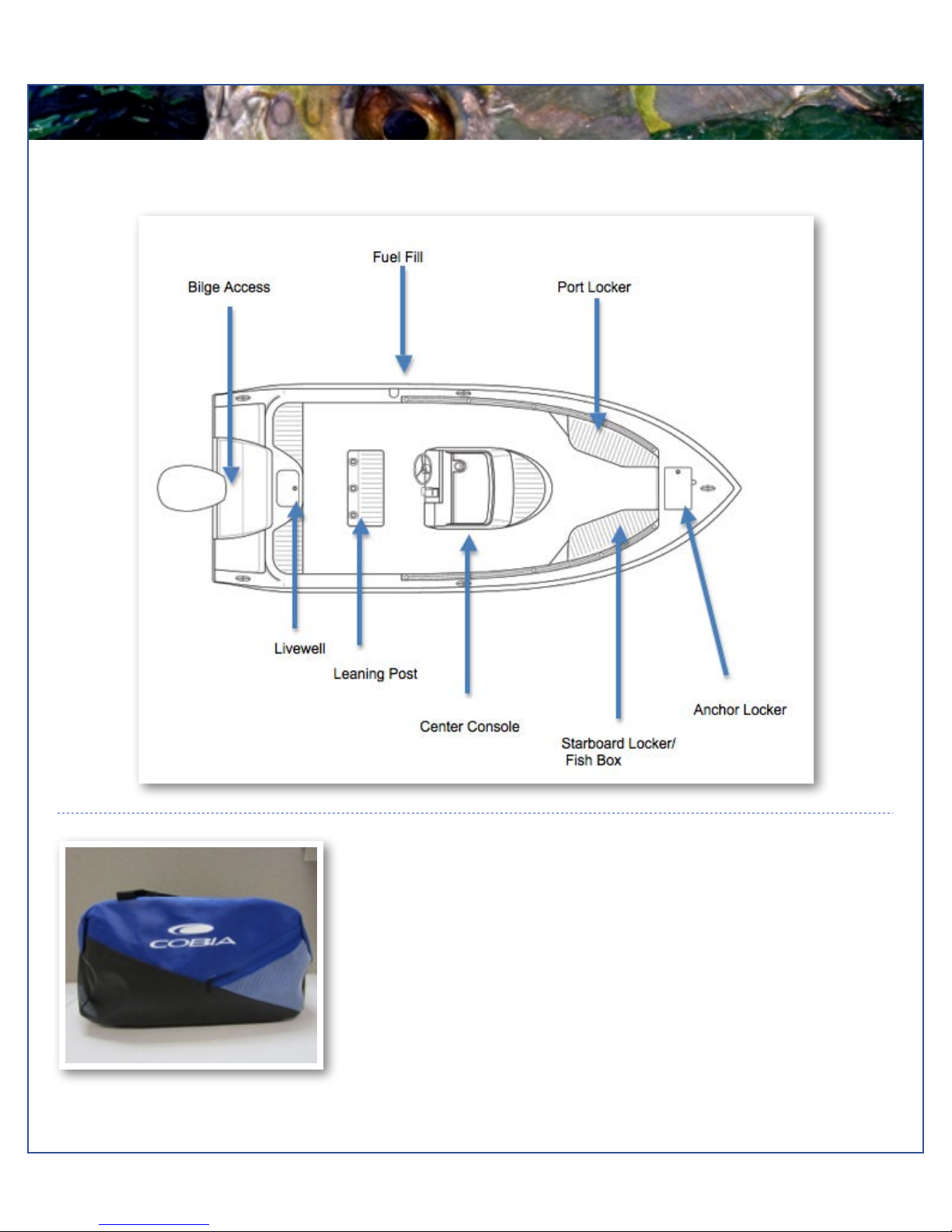
217 Boat Layout
Cobia Duffel Bag
Along with your boat, you received a Black Duffel Bag with your new Cobia 217
CC. Inside the Duffel Bag are the following items:
•
Large Livewell Standpipe
•
Short Livewell Standpipe
•
1.5” Livewell Pacifier Plug
•
2 ignition Keys and Emergency Kill Cord /Engine Stop Lanyard
•
Yamaha Engine Owner’s Manuals
•
Engine Start Cord
•
Various Appliance and Accessories Manuals
Cobia 217 Duffel Bag
Maverick Boat Company, Inc. • 3207 Industrial 29th St. • Fort Pierce,
Florida 34946 • (772)-465-0631 or (888)-shallow • Fax: (772) 489-2168
May 30, 2012
BILGE
Bilge
The bilge of the Cobia 217 should always be checked
before and after a launch. While checking the bilge, note
that a small amount of water in the bilge is normal.
However, a large amount of water or any signs of fuel or
oil requires immediate attention. If such a situation
exists, the boat should be taken to a certified marine
technician immediately. Never pump fuel or oil
overboard while your boat is in the water.
Large quantities of water in the bilge may be an
indication of a leak or that the bilge pump and/or
automatic float switch is not functioning properly due to a
jam, clog or electrical issue. The automatic float switch is
wired to the hot side of the battery switch through the
“BILGE” fuse at the battery switch panel. When
functioning properly, the float switch activates the bilge
pump to pump water overboard once water in the bilge
reaches a level that submerges the switch.
If your bilge pump does not come on when the float
switch is submerged, attempt to manually turn on the
bilge pump on your switch panel. If the bilge pump
comes on and evacuates the water, it is clear that the
float switch is not functioning properly. If the bilge pump
does not come on via the switch panel, check the
breaker panel inside the console to see if a breaker has
been tripped. If the breaker has been tripped, reset it,
and turn the switch on again, listening for the bilge pump
to turn on.
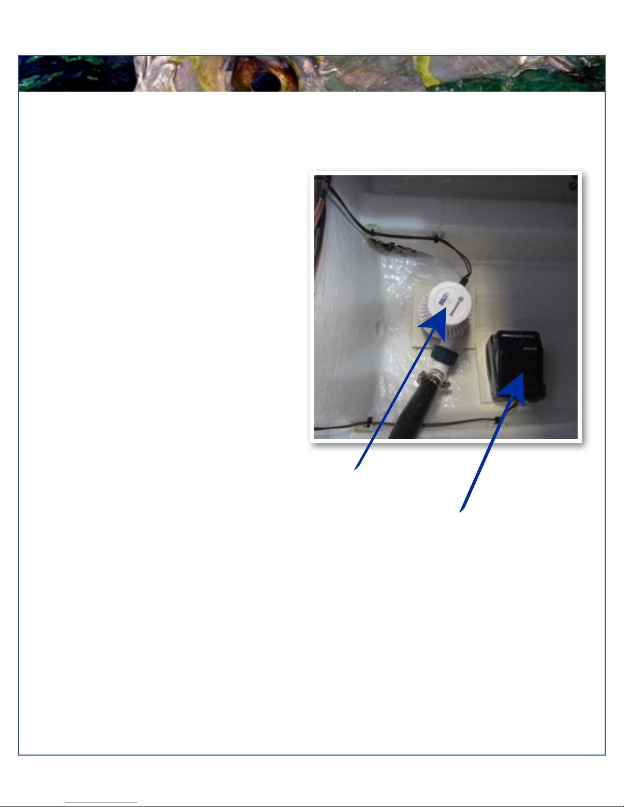
If the bilge pump fails to turn on, turn the battery switch to the OFF position, then unhook the bilge pump from its cradle
by pressing down on the blue tabs on the cradle and gently turning the top of the pump. You will feel the pump release
from the cradle. The entire bilge pump and wiring should release from the cradle. After removing the pump, check the
underside and impeller areas for miscellaneous items that might clog the pump. If any obstructions are present remove
the debris and set the pump back into the cradle. Once set back in the cradle, press the blue tab down and rotate the
pump until you feel it snap back in place. Once this is completed you can try to turn the pump on again.
If the bilge pump still does not turn on, it likely needs to be replaced. It is not recommended to use your boat if the bilge
pump and/or float switch are not functioning properly.
Bilge Pump
Automatic Float Switch
Maverick Boat Company, Inc. • 3207 Industrial 29th St. • Fort Pierce,
Florida 34946 • (772)-465-0631 or (888)-shallow • Fax: (772) 489-2168
May 30, 2012
SYSTEMS
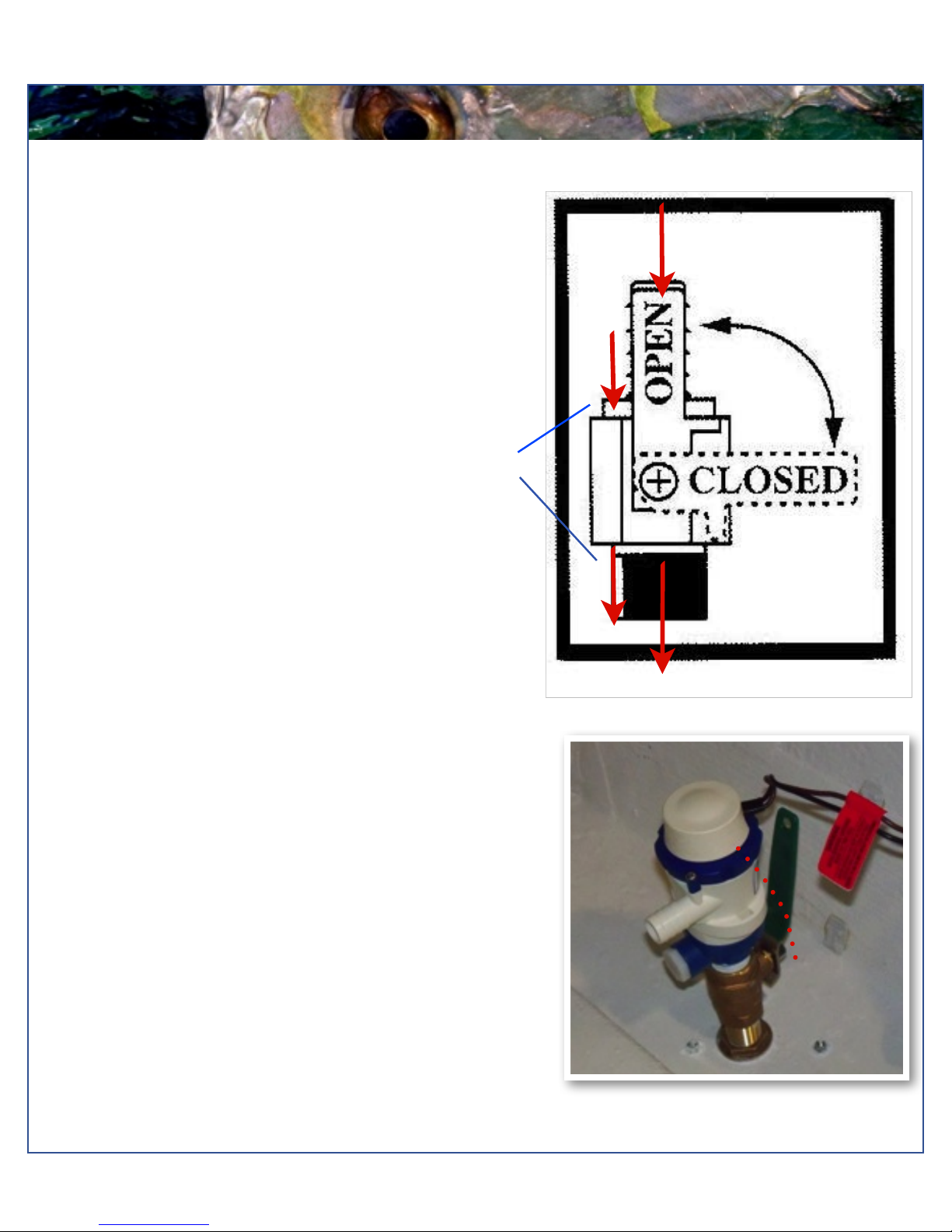
Ball Valves
Ball valves can be used to serve several purposes. They
allow seawater to enter the boat, in the case of livewells,
and they also act as a safeguard to stop water from
entering. To tell which position a ball valve is in, open or
closed, look at the valve and determine the direction of
flow. When the ball valve handle is in the same position
as the direction of flow, the valve is in the “OPEN”
position. When the ball valve handle appears to cross the
direction of flow, the valve is in the “CLOSED” position.
217 Deckdrain System
The deckdrain system is equipped with 1 1/2” thru hull
fittings through the aft port and starboard hull sides.
These fittings have to be installed lower than the drains in
the cockpit floor so that gravity will allow the cockpit to
drain free of water. This puts these fittings very close to
the water line of the hull. These drains are rigged with ball
valves that can be opened and closed to control the flow
of water. In the open position, these ball valves will allow
water to flow freely from the cockpit, thus making the boat
“self-bailing”. When closed, no water will be allowed to
travel to or from the cockpit.
Water Flow
217 Livewell Pump Assembly
The livewell pump assembly is composed of a scoop
strainer mounted to the bottom of the hull, a thru hull
fitting, ball valve assembly, and the pump. As you can
see, the ball valve assembly is in the “OPEN” position.
This is the correct position for the operation of the livewell
system.
THE LIVEWELL PUMP
ASSEMBLY IN THE “OPEN
POSITION
Maverick Boat Company, Inc. • 3207 Industrial 29th St. • Fort Pierce,
Florida 34946 • (772)-465-0631 or (888)-shallow • Fax: (772) 489-2168
CLOSED
 Loading...