

Page 1
User Manual
The most important thing we build is trust.
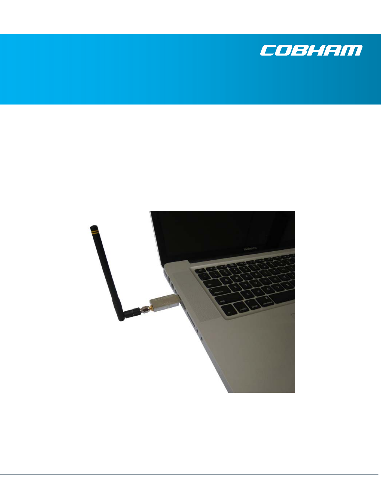
USB Wireless Control Module (UWCM)
Cobham Surveillance
GMS Products
1916 Palomar Oaks Way Ste 100
Carlsbad, CA 92008
100-M0126X1A 04/09/10 T: 760-496-0055
F: 760-496-0057
www.cobham.com/gms
Page 2

REVISION HISTORY
Version
Date Author Comments
X1 09-21-09 Doug Freeman Initial release.
100-M0126X1A 04/09/10 2 of 23
www.cobham.com/gms
Page 3

Table of Contents
1.0 Acronyms.................................................................................................................................................5
2.0 Introduction.............................................................................................................................................6
2.1 Key System Features............................................................................................................................6
2.2 Warranty..............................................................................................................................................6
2.3 Safe Operating Procedures...................................................................................................................7
3.0 Hardware Overview..................................................................................................................................7
3.1 Interface Connectors............................................................................................................................ 7
3.1.1 RF In / Out....................................................................................................................................7
3.1.2 I/O................................................................................................................................................7
4.0 Software Overview...................................................................................................................................7
4.1 System Requirements...........................................................................................................................7
4.2 Software Installation............................................................................................................................7
4.2.1 GUI Application Installation.........................................................................................................7
4.2.2 USB Driver installation................................................................................................................12
4.3 Software Operation............................................................................................................................18
4.3.1 Start the application...................................................................................................................18
4.3.2 Main Screen................................................................................................................................18
5.0 Specifications.........................................................................................................................................23
5.1 RF Related...........................................................................................................................................23
5.2 Serial Communications.......................................................................................................................23
5.3 RF Connector......................................................................................................................................23
5.4 General...............................................................................................................................................23
List of Figures
Figure 1 - System Basic Function ..................................................................................................................................................................... 6
Figure 2 - Removable Disk Root Directory Structure .............................................................................................................................. 8
Figure 3 - Location of Setup Utility and Initialization Screen ............................................................................................................ 8
Figure 4 - Microsoft .NET Framework 2.0 End User License Agreement (EULA) ....................................................................... 9
Figure 5 - Frameworks Initial Installation Screen ..................................................................................................................................... 9
Figure 6 - Frameworks Installation Progress Screen ............................................................................................................................ 10
Figure 7 - Possible Framework Installation Screen for Slow Systems ......................................................................................... 10
Figure 8 - Initial Screen for the Actual WCM GUI Setup Wizard ................................................................................................... 10
100-M0126X1A 04/09/10 3 of 23
www.cobham.com/gms
Page 4

Figure 9 - Installation Folder Selection Screen ....................................................................................................................................... 11
Figure 10 - WCM GUI Installation Progress Screen ............................................................................................................................. 11
Figure 11 - Installation Completed Screen ............................................................................................................................................... 12
Figure 12 - USB Extension Cable ................................................................................................................................................................... 12
Figure 13 - Windows XP Found New Hardware Wizard ..................................................................................................................... 13
Figure 14 - Selection of Advanced Settings ............................................................................................................................................. 13
Figure 15 - Selection of Driver file Location ............................................................................................................................................ 14
Figure 16 - Windows XP Looking for the Correct Driver .................................................................................................................... 14
Figure 17 - Windows XP has Located the Correct Driver ................................................................................................................... 15
Figure 18 - Possible Windows Logo Testing Warning Screen ......................................................................................................... 15
Figure 19 - Windows XP Setting a System Restore Point .................................................................................................................. 16
Figure 20 - Windows XP Actually Loading the Driver .......................................................................................................................... 16
Figure 21 - Driver Successfully Loaded ...................................................................................................................................................... 17
Figure 22 - XP Operating System Reports New Hardware Ready .................................................................................................. 17
Figure 23 - Assignment of Serial Port by Operating System ............................................................................................................ 17
Figure 24 - UWCM Desktop Icon .................................................................................................................................................................. 18
Figure 25 - GUI Main Screen ........................................................................................................................................................................... 19
Figure 26 - GUI Communications Section ................................................................................................................................................ 19
Figure 27 - GUI Power Control Section ...................................................................................................................................................... 20
Figure 28 - Powering on Wait Screen ......................................................................................................................................................... 20
Figure 29 - Communications Error Screen ................................................................................................................................................ 20
Figure 30 - GUI Connected and Communicating with Remote VMT .......................................................................................... 21
Figure 31 - Change of Configuration Wait Screen................................................................................................................................ 21
Figure 32 - Menu Selection after ALT is pressed ................................................................................................................................... 22
Figure 33 - File Menu Selections ................................................................................................................................................................... 22
Figure 34 - Configuration Menu Selections ............................................................................................................................................. 22
Figure 35 - Help Menu Selections ................................................................................................................................................................. 22
Figure 36 - About Screen .................................................................................................................................................................................. 23
100-M0126X1A 04/09/10 4 of 23
www.cobham.com/gms
Page 5

1.0 Acronyms
This section lists and describes the various acronyms used in this document.
Name
Meaning
GUI Graphical User Interface
ISM Industrial, Scientific, and Medical
VMT VETA Miniature Transmitter
WCM Wireless Control Module
100-M0126X1A 04/09/10 5 of 23
www.cobham.com/gms
Page 6

2.0 Introduction
The USB Wireless Control Module (UWCM) is a small USB connected and powered device that allows
User-level control and status monitoring of a remote system thru the host computer that it is attached to.
It is designed to communicate with the Wireless Control Module (WCM), a tiny transceiver that is
designed to be mounted close to a covert transmitter.
The system, at its most basic level, is a remote transmitter managed by a local controller using a wireless
link.
Figure 1 - System Basic Function
The system’s command devices include simple control panels that allow the selection of up to 16 Set-Up
Groups/Configurations, Encryption Enable/Disable and selection of 3 RF power levels. Status indicators
provide battery level and remote temperature monitoring with an indication of the presence of input
video.
2.1 Key System Features
Provides Remote
o DC PWR Control
o Battery/PWR Monitoring
o RS-232 Communications
o Temperature Monitoring
Very small
Low Power Consumption
2.2 Warranty
GMS offers a 12-month standard product warranty. During this period, should the customer encounter
a fault with the equipment we recommend the following course of action:
If fault persists, call our support line and report the fault. If fault persists and you are informed
to return the product, please obtain an RMA number from the GMS support department or
website and ship the equipment with the RMA number displayed and a description of the
fault. Please email the support section the airway bill/consignment number for tracking
purposes.
Depending on the nature of the fault, GMS will endeavor to repair the equipment and return it to the
customer within 14 days of the item arriving at our workshops. Obviously, it is impossible to cater for
100-M0126X1A 04/09/10 6 of 23
www.cobham.com/gms
Page 7

all types of faults and to manage 100% replacement part availability, and delays are sometimes
inevitable.
Please contact GMS for details of packages that can be tailored to meet your individual needs,
whether they are service availability, technical training, local geographic support, or dedicated spares
holdings.
2.3 Safe Operating Procedures
• Operate within the environmental limits specified for the product.
• Only authorized, trained personnel should open the product. There are no functions that
require the User to access the product’s interior.
• Do not operate without an antenna.
• Do not operate with the controller antenna closer than 6 feet from the WCM antenna.
3.0 Hardware Overview
3.1 Interface Connectors
3.1.1 RF In / Out
SMA-F
3.1.2 I/O
A USB type A connector provides both power and serial communications.
4.0 Software Overview
The software is a simple graphical user interface (GUI) that controls operator level functions of the VMT.
4.1 System Requirements
The application has been tested on, Windows XP SP3. For other operating systems suitable drivers may
have to be found or created.
Note. The 64-bit edition of Microsoft Windows Vista only accepts digitally signed driver installation files.
The driver files in this software package are not signed and will not be accepted. They can however be
used on 32-bit edition of Windows Vista.
4.2 Software Installation
A typical windows installation wizard that prompts the user for required input controls the software
installation. After the installation of the GUI application, a USB driver must also be installed.
4.2.1 GUI Application Installation
The setup utility is located in the SW folder on the root directory (Figure 2) of the removable disk.
100-M0126X1A 04/09/10 7 of 23
www.cobham.com/gms
Page 8

Figure 2 - Removable Disk Root Directory Structure
Double click the setup icon. The utility will start with an initialization screen (Figure 3).
Figure 3 - Location of Setup Utility and Initialization Screen
The utility checks that Microsoft .NET Framework 2.0 is installed on the computer. This framework is a
prerequisite for the installation of the application software. If the Framework is not found, the utility will
begin installation of the framework. The first part of that installation is the Microsoft end user license
agreement (EULA). Accept the agreement to start the installation (Figure 4).
100-M0126X1A 04/09/10 8 of 23
www.cobham.com/gms
Page 9

Figure 4 - Microsoft .NET Framework 2.0 End User License Agreement (EULA)
Once the EULA is accepted, the installation of the .NET framework continues (Figure 5).
Figure 5 - Frameworks Initial Installation Screen
The Framework installation takes a considerable amount of time. The installation progress is displayed in
the screen status bar (Figure 6).
100-M0126X1A 04/09/10 9 of 23
www.cobham.com/gms
Page 10

Figure 6 - Frameworks Installation Progress Screen
If the computer is slower that the installation program expected, the screen in Figure 7 is shown. This does
not necessarily indicate a problem. Be patient and the Framework installation will eventually finish.
Figure 7 - Possible Framework Installation Screen for Slow Systems
Once the Framework installation is completed, or confirmed, the application setup wizard is displayed
(Figure 8).
Figure 8 - Initial Screen for the Actual WCM GUI Setup Wizard
The Select Installation Folder screen is next. A default location for the installation is provided. If you do
not accept the default, you must remember where you installed the files to install the USB driver later.
100-M0126X1A 04/09/10 10 of 23
www.cobham.com/gms
Page 11

Figure 9 - Installation Folder Selection Screen
The actual installation begins once the location has been accepted (Figure 10).
Figure 10 - WCM GUI Installation Progress Screen
The installation is quickly accomplished and the wizard displays an Installation Complete screen (Figure
11).
100-M0126X1A 04/09/10 11 of 23
www.cobham.com/gms
Page 12

Figure 11 - Installation Completed Screen
4.2.2 USB Driver installation
Plug the UWCM into a free USB port on the PC. If your PC does not accommodate the physical size of the
unit, an USB extension cable (Figure 12) can be used.
Figure 12 - USB Extension Cable
100-M0126X1A 04/09/10 12 of 23
www.cobham.com/gms
Page 13

When the USB-dongle is plugged in first time, the Found New Hardware Wizard it will appear (Windows
XP) as in Figure 13. Select “No, not at this time” and click Next.
Figure 13 - Windows XP Found New Hardware Wizard
The Windows installation Wizard will now start to guide the user through the driver installation procedure.
Please select “Install from a list or specific location” as shown in Figure 14
Figure 14 - Selection of Advanced Settings
100-M0126X1A 04/09/10 13 of 23
www.cobham.com/gms
Page 14

Click ‘Next’ to advance to the next step. Select “Search for the best driver in these locations” as
shown in Figure 15. Provide the location for the search based on the installation location of the
application. The default location is shown.
Figure 15 - Selection of Driver file Location
Click Next to advance to the next step. Windows will now search for the driver, which may take some
time (see Figure 16).
Figure 16 - Windows XP Looking for the Correct Driver
100-M0126X1A 04/09/10 14 of 23
www.cobham.com/gms
Page 15

Once Windows has located the correct driver it will start the driver installation (Figure 17).
Figure 17 - Windows XP has Located the Correct Driver
You are now likely to encounter the warning dialog shown in Figure 18. If that is the case, you can safely
click ‘Continue anyway’ and the driver installation will resume.
Figure 18 - Possible Windows Logo Testing Warning Screen
Windows will establish a restore point as shown in Figure 19
100-M0126X1A 04/09/10 15 of 23
www.cobham.com/gms
Page 16

Figure 19 - Windows XP Setting a System Restore Point
Finally, Windows will install the USB driver as shown in Figure 20.
Figure 20 - Windows XP Actually Loading the Driver
Upon completion of the installation, windows will provide a final wizard screen (Figure 21) and a pop-up
from the status bar (Figure 22).
100-M0126X1A 04/09/10 16 of 23
www.cobham.com/gms
Page 17

Figure 21 - Driver Successfully Loaded
Figure 22 - XP Operating System Reports New Hardware Ready
When Windows has finished installing the device, a new serial port will show in the device manager in
Windows.
Figure 23 - Assignment of Serial Port by Operating System
100-M0126X1A 04/09/10 17 of 23
www.cobham.com/gms
Page 18

Note. The port number assigned to the USB Virtual Serial port is arbitrary. You may change it to an
alternative port number as follows: Right click on the port in the device manager and choose
“Properties” > “Port settings” > “Advanced” to change.
4.3 Software Operation
4.3.1 Start the application
The application software can be launched using the task bar (Start -> All Programs - >Cobham -> UWCM)
or by double clicking the desktop icon (Figure 24) that the installation program installed.
Figure 24 - UWCM Desktop Icon
4.3.2 Main Screen
The main screen (Figure 25 ) is composed of three sections with a menu bar and status bar. The first
section (Figure 26), at the top left, allows the user to select the serial port that the UWCM is connected
through. It also reports on the status of the connection. The second section (Figure 27), at the top right,
controls the remote power switch providing power to the VMT. The third section, the remainder of the
screen, controls the VMT. It controls configuration, RF power level, and encryption.
100-M0126X1A 04/09/10 18 of 23
www.cobham.com/gms
Page 19

Figure 25 - GUI Main Screen
4.3.2.1 Select correct communications port
To establish a connection to the remote WCU and VMT, fist select the serial communications port
associated with the UWCM from the Select Serial Port drop-down control (Figure 26). The connection
indicator will remain white until the remote VMT is actually turned on and responding to queries from the
application.
Figure 26 - GUI Communications Section
4.3.2.2 Turn the transmitter power on
When the user is ready to activate the remote VMT, Click the Turn Transmitter ON command button
(Figure 27).
100-M0126X1A 04/09/10 19 of 23
www.cobham.com/gms
Page 20

Figure 27 - GUI Power Control Section
If the UWCM is able to communicate with the remote WCM, and the remote WCM responds that it was
able to activate the remote power switch, the wait screen (Figure 28) is displayed while the VMT initializes.
Figure 28 - Powering on Wait Screen
If communications could not be established between the local and remote units, the problem screen
(Figure 29) is displayed.
Figure 29 - Communications Error Screen
When communications is established, the connection indicator will turn green. If that indicator turns
yellow, it means that errors have been detected in the communications stream. The VMT Power Control
indicator will also turn green indicating that the remote power switch has been turned on.
100-M0126X1A 04/09/10 20 of 23
www.cobham.com/gms
Page 21

4.3.2.3 VMT Control and Status
Figure 30 - GUI Connected and Communicating with Remote VMT
The main display will provide the status of the VMT. The status bar at the bottom of the screen will
provide the temperature and battery voltage of the remote WCU.
The MODE command button toggles the encryption on or off on the VMT. The indicator next to the key
icon displays the current encryption status. A yellow indication means that encryption is on. A white
indication means that encryption is off.
The RF command button toggles the VMT power through off, low power, and high power. If the RF power
is off, the RF indicator and both sections of the indicator next to the antenna icon will be white. Low
power is indicated by the RF indicator being green along with the lower segment of the indicator next to
the antenna icon. High power is indicated by both segments being green.
The CONFIG command button increments the current VMT configuration as indicated by the group of 16
indicators above the button. A specific configuration can also be selected by clicking on the specific
configuration indicator. While the configuration is changing, the wait screen (Figure 31) is displayed.
Figure 31 - Change of Configuration Wait Screen
100-M0126X1A 04/09/10 21 of 23
www.cobham.com/gms
Page 22

4.3.2.4 Menu Selections
Pressing the ALT key will display the available menu shortcut keys (Figure 32). The main menu has File,
Configuration, and Help selections.
Figure 32 - Menu Selection after ALT is pressed
The File menu contains an Exit command (Figure 33). This closes the application.
Figure 33 - File Menu Selections
The Configuration menu contains a Factory Setup command (Figure 34) that is not accessible by the user.
Figure 34 - Configuration Menu Selections
The Help menu contains an About command (Figure 35) that opens up the applications information
screen. (Figure 36)
Figure 35 - Help Menu Selections
100-M0126X1A 04/09/10 22 of 23
www.cobham.com/gms
Page 23

5.0 Specifications
5.1 RF Related
Operating Frequency: 902-928 MHz (ISM band)
Frequency Tuning Resolution: 184.570 kHz
# of RF channels: 140
Modulation type: Frequency Hopping w/ Gaussian Frequency Shift Keying (GFSK)
Forward Error Correction
RF Channel Data Rate: 500 Kbps
Programmable output power from -30 dBm to +10 dBm
5.2 Serial Communications
USB (Max data rate 12 Mbps)
5.3 RF Connector
SMA –F
5.4 General
Voltage USB Powered +5 VDC
Current 45 mA
Temperature -10 C to 70 C Degrees
Humidity 0 to 95% non-condensing
Size 2.34” x 0.91” x 0.23”/ 5.94 cm x 2.3 cm x 0.58 cm
Weight less than 0.72 oz / 20 g
Figure 36 - About Screen
100-M0126X1A 04/09/10 23 of 23
www.cobham.com/gms
 Loading...