

Page 1

Resource Identifier 100145
Revision: 8.0
Solo7 Nano Transmitter
Video, Transmitters, Solo7 Nano Transmitter
Tactical Communications and Surveillance
Commercial in Confidence
The Cobham Centre - Solent
Fusion 2
1100 Parkway
Solent Business Park
Whiteley
Hampshire
PO15 7AB
United Kingdom
+44 (0)1489 566 75 0
Page 2

Solo7 Nano Transmitter
Commercial in
Confidence
Video, Transmitters, Solo7 Nano
Transmitter
100145
Revision: 8.0
Commercial in
Confidence
Page 0-1
0. Preface
0.1 About this Document
This document contains relevant details r eq uir ed for the Op eration and Administration of the
equipment or system.
Since the available functions are licensed and depend on the specific implementation, not all
the functions and or applications contained in this document may be relevant or applicable to
the system you will be working with.
Actual screen presentation may differ from those in this document due to software changes
or your browser configuration.
0.2 Who Should Read this Book
This document is meant for anyone interested in how the system can best be used, but it is
of most benefit to:
Operators who are in charge of the daily operation of the equipment.
Installers who are responsible for the pre-installation, on-site install ation and
configuration of the system in the end-user environment.
Maintainers who are responsible for maintaining the equipment or system.
0.3 Assumed Knowledge
Throughout this book it is assumed that the reader has a thorough knowledge of:
Basic Personal Computer Operations.
Basic Radio Frequency (RF) Principles.
0.4 Notice about Specification s
While Cobham makes every attempt to maintain the accuracy of the information contained in
its product manuals, the information is subject to change without notice. Performance
specifications included in this manual are design-centre specifications and are included for
customer guidance and to facilitate system installation. Actual operating performance may
vary.
0.5 Notice about this Guide
The product described in this manual is subject to continuous development and
improvement. All particulars of the product and its use (including the information and
particulars in this guide) are given by Cobham in good faith. However, it is acknowledged
that there may be errors or omissions in this guide.
Page 3

Solo7 Nano Transmitter
Commercial in
Confidence
Video, Transmitters, Solo7 Nano
Transmitter
100145
Revision: 8.0
Commercial in
Confidence
Page 0-2
0.6 Typographic Conventions
This document uses these typographic conventions to identify text that has a special
meaning:
Typographic Convention
Example
TEXT in small capitals represents a specific key press on
the console keyboard or hardware panel.
ESC, F1, SHIFT
The + sign means “hold down the first key while pressing
the second key”.
Press CTRL+C to abort
<Text> Serves as a placeholder for variable text that you
will replace as appropria te t o its context.
Use the filename
<systemname>.sys for…
Text in bold emphasises a new word or term of
significance.
We call this a protocol and
its function is…
[-a] Text in these brackets indicates an optional
component that can be left out.
Ls [-a]
NN This indicates a value entered on a numeric keypad.
45 on the numeric keypad
Successive menu selections are shown using arrows
to indicate a sub-menu. In this example this would mean:
Select the Insert menu, then select picture, then select
from file.
Insert > picture > from file
0.7 Symbols
This document uses these symbols to highlight important information:
WARNING: A written notice given to a reader when a situatio n might result in personal
injury or loss of life.
CAUTION: A written notice given when a situation might result in damage to or destruction
of equipment or systems.
Note: A written notice given to draw the reader’s attention to something or to supply
additional information.
Page 4

Solo7 Nano Transmitter
Commercial in
Confidence
Video, Transmitters, Solo7 Nano
Transmitter
100145
Revision: 8.0
Commercial in
Confidence
Page 0-3
0.8 Trademarks
All trademarks or registered trademarks that appear in this document are the property of
their respective owner s.
© Cobham TCS Limited.
Cobham TCS Limited owns the copyright of this document which is supplied in confidence
and must not be used for any purpose other than for which it is supplied and must not be
reproduced without permission in writing from the owners.
0.9 Related Documents
You may also need to read:
Document
Source
Solo Concept Guide
Cobham Tactical Communications and Surveillance
IP Concept Guide
Cobham Tactical Communications and Surveillance
0.10 Document History
This document was written and produced by the Cobham Technical Publications Team.
This is a change controlled document. Each main page of this document displays a revision
number and date at the bottom left corner of the page. The revision is also indicated in the
table below.
Changes to any page will raise the revision status of the whole document.
Revision
Date
Authors
Summary of Changes
SharePoint
Page 5

Solo7 Nano Transmitter
Commercial in
Confidence
Video, Transmitters, Solo7 Nano
Transmitter
100145
Revision: 8.0
Commercial in
Confidence
Page 0-4
Contents
0. Preface ..................................................................................... 0-1
0.1 About t his Document ....................................................................................... 0-1
0.2 Who Should Read this Book .............................................................................. 0-1
0.3 Assumed Knowl ed g e ........................................................................................ 0-1
0.4 Notice abo ut Sp ecifi cat i ons ............................................................................... 0-1
0.5 Notice abo ut this Guid e .................................................................................... 0-1
0.6 Typ ograp hi c Conv ent i o ns ................................................................................. 0-2
0.7 Symbols.......................................................................................................... 0-2
0.8 Trademarks .................................................................................................... 0-3
0.9 Related Documents ......................................................................................... 0-3
0.10 Document History ......................................................................................... 0-3
Contents ......................................................................................... 0-4
1. Systems Description .................................................................. 1-1
1.1 What is the SOLO7 Nano Transmitter? .............................................................. 1-1
1.2 What are t he Features and Benefits of the Nano Transmitter? ............................. 1-2
1.3 What is the SOLO7 HD Nano Transmitter? ......................................................... 1-3
1.4 Getting an Overview of the Nano Transmitter .................................................... 1-4
1.1 Getting an Overview of the HD Nano Transmitter ............................................... 1-6
2. Getting Started .......................................................................... 2-7
2.1 Identify i ng y o ur Device .................................................................................... 2-7
2.2 Unpacking y o ur Nano Transmitter ..................................................................... 2-7
2.3 Unpacking y o ur HD Nano Transmitter ............................................................. 2-10
2.4 About t he Labels on your Nano Transmitter ..................................................... 2-10
2.5 Planning the Hardware Installation .................................................................. 2-12
2.6 Identify i ng the Variants of Nano Transmitter .................................................... 2-12
2.7 Identify i ng the Options of Nano Transmitter .................................................... 2-12
2.1 Identify i ng the Variants of HD Nano Transmitter .............................................. 2-13
2.2 Identify i ng the Options of HD Nano Transmitter ............................................... 2-14
2.3 About t he Software wit h your Nano T rans mitt e r ............................................... 2-15
3. Controls, Connections and Indicators ......................................... 3-17
3.1 About Control s , Connections and Ind i cat o r s ..................................................... 3-17
3.2 Exploring the Top Panel – Nano Transmitter .................................................... 3-17
3.3 Exploring the Bottom Panel – Nano Transmitter ............................................... 3-18
3.4 Exploring the Side Panel – Nano Transmitter ................................................... 3-19
3.5 Exploring the Top Panel – HD Nano Transmitter ............................................... 3-19
3.6 Exploring the Bottom Panel – HD Nano Transmitter .......................................... 3-20
3.7 Exploring the Side Panel – HD Nano Transmitter .............................................. 3-21
4. Setting up your Nano Transmitter .............................................. 4-22
4.1 Connecting t he Ant enna ................................................................................. 4-22
Page 6

Solo7 Nano Transmitter
Commercial in
Confidence
Video, Transmitters, Solo7 Nano
Transmitter
100145
Revision: 8.0
Commercial in
Confidence
Page 0-5
4.2 Connecting DC Po wer .................................................................................... 4-22
4.3 Connecting AC P o wer..................................................................................... 4-23
4.4 Connecting Video Signals – Composite 1 ......................................................... 4-23
4.5 Connecting Audi o Signals ............................................................................... 4-24
4.6 Connecting Dat a Sig nal s ................................................................................ 4-25
4.7 Connecting Control Signals ............................................................................. 4-25
5. Basic Operation ........................................................................ 5-26
5.1 Start i ng and Stopping the Nano Transmi tter .................................................... 5-26
5.2 Wearing t he Nano T r ansmitt er on your Body ................................................... 5-27
6. Advanced Operation ................................................................. 6-28
6.1 About Encryption ........................................................................................... 6-28
6.2 Setti ng up Encryptio n .................................................................................... 6-28
6.3 About High Lineari ty and Low Power Modes ..................................................... 6-31
7. Advanced Setup ....................................................................... 7-33
7.1 About Advanced Set up ................................................................................... 7-33
7.2 Installi ng the Nano TX Controller on your PC ................................................... 7-33
7.3 Connecting y o ur PC to the Nano TX using Serial ............................................... 7-33
7.4 Explo ri ng the Nano TX Controller M ai n Window ................................................ 7-36
7.5 Performi ng a Quick Setup ............................................................................... 7-37
7.6 Work ing with the Unit Status Panel ................................................................. 7-42
7.7 Work ing with the Switch Panel........................................................................ 7-44
7.8 Work ing with the Unit Tab ............................................................................. 7-45
7.9 Work ing with the Modulation T ab ................................................................... 7-51
7.10 Working with the Audio Tab ........................................................................ 7-58
7.11 Working with the Video Tab ........................................................................ 7-61
7.12 Working with the Misc Tab .......................................................................... 7-65
8. Appendix A – Cautions and Warnings ........................................ 8-69
8.1 Cautions and W arni ng s .................................................................................. 8-69
8.2 EMC / Safety and Radio Approvals .................................................................. 8-70
8.3 CE Marking ................................................................................................... 8-70
9. Appendix B - Care and Maintenance .......................................... 9-71
9.1 Caring for y o ur Equipment ............................................................................. 9-71
9.2 Charging ....................................................................................................... 9-71
9.3 Work ing with Lithium Batteries ....................................................................... 9-71
9.4 Cleaning ....................................................................................................... 9-72
9.5 Storage ........................................................................................................ 9-72
9.6 Repairs ......................................................................................................... 9-72
9.7 Getting Technical Support .............................................................................. 9-72
9.8 Using the Cobham RMA Service ...................................................................... 9-73
10. Appendix C-Glossary ............................................................ 10-74
10.1 Glossary .................................................................................................. 10-74
Page 7

Solo7 Nano Transmitter
Commercial in
Confidence
Video, Transmitters, Solo7 Nano
Transmitter
100145
Revision: 8.0
Commercial in
Confidence
Page 0-6
11. Appendix D – Reference Material .......................................... 11-83
11.1 Licensing your Unit ................................................................................... 11-83
11.2 Upgrading your Firmware .......................................................................... 11-85
11.3 Pinouts .................................................................................................... 11-85
11.4 Running the Nano TX Controller in Logging Mode ........................................ 11-87
11.5 Recovering the Logging File....................................................................... 11-89
Page 8

Solo7 Nano Transmitter
Commercial in
Confidence
Video, Transmitters, Solo7 Nano
Transmitter
100145
Revision: 8.0
Commercial in
Confidence
Page 1-1
1. Systems Description
The subject equipment of this User Guide is:
Equipment Title
Part Number
SOLO7 Nano Transmitter
SOL7NTX-
SOLO7 HD Nano Transmitter
SOL7HDNTX-
Figure 1-1 – SOLO7 Nano Transmitter
1.1 What is the SOLO7 Nano Transmitter?
The SOLO7 Nano Transmitter is an ultra-miniature COFDM digital video transmitter from
Cobham Tactical Communications and Surveillance, designed specifically for covert video
installations and body-worn applications.
With proven Cobham COFDM technology at its core, the excep tionally small size and low
power consumption (typically 3.7W @ 100mW RF power) of the SOLO7 Nano transmitter
make it the product of choice for covert video hides, or applications requiring long term
battery power deployments, small unmanned aerial vehicles, and body-worn or body-wire
use.
The SOLO7 Nano Transmitter employs ultra-low latency High Profile H.264 (MPEG-4 AVC)
encoding for excellent i mage quality retention over the wireless link. MPE G-4 ASP video
encoding is also available for backward compatibility with older Cobham video transmission
products. Equipped with integral COFDM modulation, the SOLO7 Nano Transmitter is ideal
for establishing rugged wireless video links in numerous environments, including mobile and
urban. Offering several user-selectable modes that trade off image quality against range, the
SOLO7 Nano Transmitter is very well suited to all mission types.
The SOLO7 Nano Transmitter supports both industry standard DVB-T modulation and
Cobham Narrowband (2.5 MHz), Ultra Narrowband (1.25 MHz) and Ultra-X (625 kHz)
bandwidths. The narrowband modes allow users to share scarce spectrum allocation
extremely efficientl y.
Page 9

Solo7 Nano Transmitter
Commercial in
Confidence
Video, Transmitters, Solo7 Nano
Transmitter
100145
Revision: 8.0
Commercial in
Confidence
Page 1-2
The SOLO7 Nano Transmitter is supplied in a simple aluminium lightweight case and features
an industry standard reliable SMA transmit connector. Video, control and power interfaces
use two Micronetics con necto rs.
The SOLO7 Nano Transmitter can be controlled via either USB or via RS232. The versatile
and intuitive Cobham Field Controller can also be used to configure and control the SOLO7
Nano transmitter.
Security is ensured with optional AES128/256 Encryption.
The SOLO7 Nano Transmitter will transmit images in a non-line of sight environment up to
750m, depending on mode and frequency.
1.2 What are the Features and Benefits of the Nano
Transmitter?
It can be very useful to understand how the features of the unit yield tangible benefits to
you. This table summarises these features and, more importantly, the benefits.
Features and Benefits Table – Nano Transmitter
Key Features
Key Benefits
Digital COFDM Modulation
Excellent performan ce - Resist ant to multipath
interference, delivers high quality video and
audio, even when mobile or in built up areas
like urban environments.
Low Delay, high quality video encoding in
MPEG-4
High reliability - Use a radio system just like it
was a line. You can choose between MPEG-4
ASP and H.264 encoding standard to suit your
application.
Compliant DVB-T Modulator and
proprietary narrowband.
True multi-mode operation - Perfect
integration with your current equipment.
100mW RF Up-Converter
Excellent range in non-line of sight
environments like cities, stadiums and
airports.
Compact and Power Efficient
Transmitters
Put the transmitter just where you need it. Get
those difficult links that ensure the success of
your operation. Never lose a link for lack of
power.
Composite Video Interfaces
Low cost of ownership - Easy connection to
your current cameras.
Integral Encryption at AES128 or AES256
(Optional).
Secure - Preserve your security of
transmission with powerful, simple to operate
encryption.
Page 10

Solo7 Nano Transmitter
Commercial in
Confidence
Video, Transmitters, Solo7 Nano
Transmitter
100145
Revision: 8.0
Commercial in
Confidence
Page 1-3
Choice of UHF, L, S or C band solutions
Improved operational efficiency - Efficient use
of limited radio spectrum. Choose the
frequency that suits your operations. Select
licence free bands for some operations. Avoid
cluttered parts of the radio spectrum.
Low Latency
Enables real time operat ions l ike remote
vehicle control or UAV operat i ons.
Sixteen Presets Avail a ble
Better use of assets and resour c es - You can
preset frequencies into any of sixteen presets.
Configure the whole operation in the calm of
the base then the operations staff just have to
quickly select the preset with one button.
High reliability and availability
Reduced maintenance requi rement, reduced
spares holding, resulting in significant cost
benefits over the life of the sy stem.
Low Mass (51g)
Suitable for discrete operation in the field.
Table 1-1 – Features and Benefits
1.3 What is the SOLO7 HD Nano Transmitter?
The SOLO7 HD Nano Transmitter is an ultra-miniature COFDM digit al video transmitter from
Cobham Tactical Communications and Surveillance, designed specifically for Point-of-View
(PoV) and body-worn applications.
With proven Cobham COFDM and H.264 encoder technology at its core, the exceptionally
small size and ultra-low power consumption (typically 7.5W ) H D Nano Transmitter enables
production teams to offer viewers stunning high definition images from the heart of the
action, in situations never previously possible due to equipment size and battery run-time
constraints.
The small size and ultra-low power consumption make the HD Nano TX ideal for UAV
‘Octocopter’ installations, enabling true long range HD broadcasting from these increasingly
popular devices for the first time. Optional lightweight, low power consumption amplifiers are
also available for even greater range capability.
The HD Nano Transmitter employs ultra-low latency High Profile H.264 (MPEG-4 AVC)
encoding for excellent i mage quality retention over the wireless link an d supports composite,
SDI, HD-SDI and HDMI video input formats.
The HD Nano Transmitter offers numerous modulation options to suit various deployment
scenarios:
Industry standard DVB-T modulation for full HD quality and compatibility with existing
systems
Cobham UMVL modulation for enhanced high speed operation (motorsports) and
improved performance at high frequencies (6 & 7GHz)
Page 11

Solo7 Nano Transmitter
Commercial in
Confidence
Video, Transmitters, Solo7 Nano
Transmitter
100145
Revision: 8.0
Commercial in
Confidence
Page 1-4
Cobham Narrowband (2.5 MHz), Ultra Narrowband (1.25 MHz) and Ultra-X (625 kHz)
bandwidths. The narrowband modes allow users to share scarce spectrum allocation
extremely efficiently.
The HD Nano Transmitter is supplied in a simple aluminium lightweight case and features an industry
standard SMA RF connector. Composit e video, audio, control and power interfaces use two latching
Omnetics connectors. A latching DIN 1.0/2.3 co-axial connector is used for the SDI / HD-SDI input
and a micro HDMI (with optional cable clamp) for the HDMI input.
The HD Nano Transmitter can be controlled via either USB or via RS232. The versatile and intuitive
Cobham Field Controller can also be used.
1.4 Getting an Overview of the Nano Transmitter
Diagram: Nano Transmitter Main System
Figure 1-2 Main System Diagram
Page 12

Solo7 Nano Transmitter
Commercial in
Confidence
Video, Transmitters, Solo7 Nano
Transmitter
100145
Revision: 8.0
Commercial in
Confidence
Page 1-5
No
Item
Function
1
SOLO7 Nano Transmitter.
Main Unit.
2
Antenna.
SMA Fitting. Must be band matched.
3
SMA 2-way receptacle (socket ) for
antenna.
Antennas connect here. Do not over
tighten – hand tight only.
4
USB Micro-B 4-way receptacle (socket).
USB Control Port for configuring
unit.
5
USB Micro-B 4-way plug (pin).
Connects to the USB Micro-B
receptacle on the side of the Nano
TX. Used to configure the unit.
6
USB Type A 4-way plug (pin).
Connects to your PC that you’ll use
to configure the Nano Transmitter.
7
Omnetics Nano Circular 6-way receptacle
(pin).
Note: They
look
like sockets but they
really are pins.
Power and Serial Control Port.
8
Omnetics Nano Circular 6-way plug
(socket).
Connects to the 6-way receptacle on
the base of the Nano Transmitter.
Carries Power and Serial Control
signals.
9
Lemo OB 3-way plug (socket).
Serial Control. You’ll connect your
Serial control cable from your PC to
this plug when configuring the unit.
10
Lemo OB 4-way plug (socket).
Power. You’ll connect your Lemo 4-
way plug (pin) from your power
supply to this plug to power the unit.
11
Lemo OB 3-way plug (socket).
Data Input. You’ll connect your
Serial data cable from your device to
this plug.
12
RCA Phono 2-way plug (socket).
For audio left (black) input.
13
RCA Phono 2-way plug (socket).
For audio right (red) input.
14
RCA Phono 2-way plug, (socket).
For video (yellow) input.
Page 13

Solo7 Nano Transmitter
Commercial in
Confidence
Video, Transmitters, Solo7 Nano
Transmitter
100145
Revision: 8.0
Commercial in
Confidence
Page 1-6
No
Item
Function
15
Omnetics Tri-Lobe Latching 9-way plug
(pin).
Carries video, audio and data.
16
Omnetics Tri-Lobe Latching 9-way
receptacle (socket).
Note: They
look
like pins but they really
are sockets.
Carries video, audio and data.
17
Phono (pins) to BNC (socket) adapter.
Enables you to connect equipment
with a BNC plug to the video
(yellow) RCA Phono 2-way plug,
(socket) on CA2254.
Table 1-2 – Main System Diagram Key
1.1 Getting an Overview of the HD Nano Transmitter
Diagram: HD Nano Transmitter Main System
Figure 1-3 HD Nano Transmitter Main System Diagram
Page 14

Solo7 Nano Transmitter
Commercial in
Confidence
Video, Transmitters, Solo7 Nano
Transmitter
100145
Revision: 8.0
Commercial in
Confidence
Page 2-7
2. Getting Started
2.1 Identifying your Device
There are two types of Nano Transmitter described in this User Guide.
This is a SOLO7 Nano Transmitter.
Its type designation is: SOL7NTX-
Size: 58mm (L) x 38mm (W) x 17mm
(H).
Weight: 51g.
Operating Temperature: -10 degrees C
to +50 degrees C.
Power Consumption: Typically 3.7W
with 100mW RF.
DC Input 5.9 to 17.8VDC Reverse
polarity protected .
This is a SOLO7 HD Nano
Transmitter.
Its type designation is: SOL7HDNTX-
Size: 67mm (L) x 68mm (W) x 22mm
(H).
Weight: 135g.
Operating Temperature: -10 degrees C
to +50 degrees C.
Power Consumption: Typically 7.5W
with 100mW RF.
DC Input 5.9 to 17.8VDC Reverse
polarity protected .
Figure 2-1 – SOLO7 Nano and HD Nano Transmitters
2.2 Unpacking your Nano Transmitter
Carefully open the packaging and remove the device. Verify that all the components have
been included in the package as shown in the packing list. Inspect the unit for shipping
damage.
Retain the packing list and all the packing materials for storage.
The codes on the picture mean:
CA – Cable Assembly
Page 15

Solo7 Nano Transmitter
Commercial in
Confidence
Video, Transmitters, Solo7 Nano
Transmitter
100145
Revision: 8.0
Commercial in
Confidence
Page 2-8
SA – Sub Assembly
AP – Assembly Part.
The codes are useful to you if you need to order a new cable sometime.
Diagram: Unpacking your Nano Transmitter
Figure 2-2 – Nano Transmitter Packing Diagram
No
Item
Notes
1
SOLO7 Nano Transmitter
SOL7NTX-100150 with a frequency range of 1.00 GHz
to 1.50 GHz in this example. Ot her frequencies are
available.
2
USB2.0 CABLE 1 Metre,
A TO MICRO-B,
AP007377
USB Micro-B 4-way plug (pin) to
USB Type A 4-way plug (pin).
Page 16

Solo7 Nano Transmitter
Commercial in
Confidence
Video, Transmitters, Solo7 Nano
Transmitter
100145
Revision: 8.0
Commercial in
Confidence
Page 2-9
No
Item
Notes
3
Audio / Video / Data
Cable Assembly, CA2254
Audio / Video / Data Cable Assembly (16.5 centimetres)
Omnetics Tri-Lobe Latching 9-way plug (socket) to
RCA Phono 2-way plug (socket), yellow, video and
RCA Phono 2-way plug (socket), red, audio right and
RCA Phono 2-way plug (socket), black, audio left and
Lemo OB 3-way plug (socket), data.
4
Power / Control Cable
Assembly, CA2253
Power / Control Cable Assembly (16.5 centimetres)
Omnetics Nano Circular 6-way plug (pin).to
Lemo OB 3-way plug (socket), Control and
Lemo OB 4-way plug (socket), Power
5
Power Cable Assembly,
CA0002
Power Cable Assembly (3 metres)
Lemo OB 4-way plug (pin) to
Banana 1-way plug (pin) red and
Banana 1-way plug (pin) black
6
Phono (pins) to BNC
(socket) adapter.
Enables you to connect equipment with a BNC plug to
the video (yellow) RCA Phono 2-way plug, (socket) on
CA2254.
Table 2-1 – Parts in the Nano Transmitter Package
Troubleshooting
I don’t have all the parts you described!
Call your Cobham contact right away and we’ll get this solved for you.
The Cobham Centre – Solent Fusion 2
1100 Parkway, Solent Business Park
Whiteley, Hampshire
PO15 7AB, England
+44 (0)1489 566 750
Note: There is a kit version of the Nano transmitter which comes complete with a camera
and battery and other cables. Please refer to the Quick Start Guide included with the kit for
details.
Page 17

Solo7 Nano Transmitter
Commercial in
Confidence
Video, Transmitters, Solo7 Nano
Transmitter
100145
Revision: 8.0
Commercial in
Confidence
Page 2-10
2.3 Unpacking your HD Nano Transmi tter
Carefully open the packaging and remove the device. Verify that all the components have
been included in the package as shown in the packing list. Inspect the unit for shipping
damage.
Retain the packing list and all the packing materials for storage.
Diagram: Unpacking your HD Nano Transmitter
Figure 2-3 – HD Nano Transmitter Packing Diagram
2.4 About the Labels on your Nano Transmitter
Which model do I have? What is its Serial Number?
This topic contains information covering placards, labels, markings, etc., showing the part
number, legend and location of each placard, label, or marking required for safety or
maintenance significant information.
Page 18

Solo7 Nano Transmitter
Commercial in
Confidence
Video, Transmitters, Solo7 Nano
Transmitter
100145
Revision: 8.0
Commercial in
Confidence
Page 2-11
Step 1: Identify the Product Label
Diagram: SOLO7 Nano Transmitter Label
Figure 2-4 – SOLO7 Nano Transmitter Label
No
Item
1
SOLO7 Group.
2
Nano Transmitter family of products.
3
Frequency range, 1.00GHz to 1.50GHz in this example.
4
Disposal mark.
5
The CE marking (also known as CE mark) is a mandatory conformity mark
on many products placed on the single market in the European Economic
Area (EEA).
The CE marking certifies that a product has met EU consumer safety, health
or environmental requirements.
6
Barcode with six digit serial number. We’ll nearly always ask you for this
number during a support call.
7
Manufacturer.
Table 2-2 – SOLO7 Nano Transmitter Label Key
Page 19

Solo7 Nano Transmitter
Commercial in
Confidence
Video, Transmitters, Solo7 Nano
Transmitter
100145
Revision: 8.0
Commercial in
Confidence
Page 2-12
2.5 Planning the Hardware Installation
During the design and layout of the system, you should give careful consideration of the
location of this and all other associated modules. Some of the items to consider include:
Space - Leave at least 100mm clearance left and right to allow for cable bending.
Proximity to other devi ces (fo r example, source equipment).
Length of cable runs.
Environmental conditions (temperature, humidity, etc.)
Access for service repair .
Compliance with local regulations.
2.6 Identifying the Variants of Nano Transmitter
Step 1: Identify the Variants
Equipment Title
Part Number
SOLO7 Nano Transmitter 200-300MHz
SOL7NTX-020030
SOLO7 Nano Transmitter 300-470MHz
SOL7NTX-030047
SOLO7 Nano Transmitter 1.00-1.50GHz
SOL7NTX-100150
SOLO7 Nano Transmitter 1.65-2.40GHz
SOL7NTX-165240
SOLO7 Nano Transmitter 1.98-2.70GHz
SOL7NTX-198270
SOLO7 Nano Transmitter 3.00-3.70GHz
SOL7NTX-300370
SOLO7 Nano Transmitter 4.40-5.00GHz
SOL7NTX-440500
SOLO7 Nano Transmitter 5.50-6.00GHz
SOL7NTX-550600
Table 2-3 – Nano Transmitter Variants
2.7 Identifying the Options of Nano Transmitter
The Nano Transmitter has two types of options:
Accessory Options
Licensing Options
Page 20

Solo7 Nano Transmitter
Commercial in
Confidence
Video, Transmitters, Solo7 Nano
Transmitter
100145
Revision: 8.0
Commercial in
Confidence
Page 2-13
Step 1: Identify the Accessory Options
Equipment Title
Part Number
Lemo to Dsub9 RS232 Control Cable
CA0001
NTX DC Power Cable
CA2250
NTX DC Power / FCON Cable
CA2370
NTX 9-way Breakout Cable
CA2298
NTX 7.4V Battery Pack (2250mAh)
NTXBAT
NTX Battery Charger (multi-region)
NTXBATCH
Table 2-4 – Nano Transmitter Accessory Options
Step 2: Identify the Licensing Options
Equipment Title
Part Number
Enables 1.25MHz Narrowband modulation and backward
compatible MPEG-4 ASP encoder
TX-UN
Enables 625kHz Narrowband modulation (requires TX-UN)
TX-UXN
Enables UMVL modulation
TX-UMVLUP
AES 128 Bit encryption
AES128TX
AES 256 Bit encryption
AES256TX
Table 2-5 – Nano Transmitter Licensing Options
2.1 Identifying the Variants of HD Nano Transmitter
Step 1: Identify the Variants
Equipment Title
Part Number
SOLO7 HD NanoTX 5.50-6.00GHz
SOL7HDNTX-550600
SOLO7 HD NanoTX 4.40-5.00GHz
SOL7HDNTX-440500
SOLO7 HD NanoTX 3.00-3.70GHz
SOL7HDNTX-300370
SOLO7 HD NanoTX 1.98-2.70GHz
SOL7HDNTX-198270
Page 21

Solo7 Nano Transmitter
Commercial in
Confidence
Video, Transmitters, Solo7 Nano
Transmitter
100145
Revision: 8.0
Commercial in
Confidence
Page 2-14
Equipment Title
Part Number
SOLO7 HD NanoTX 1.65-2.40GHz
SOL7HDNTX-165240
SOLO7 HD NanoTX 1.00-1.50GHz
SOL7HDNTX-100150
SOLO7 HD NanoTX 300-470MHz
SOL7HDNTX-030047
SOLO7 HD NanoTX 200-300MHz
SOL7HDNTX-020030
Table 2-6 – HD Nano Transmitter Variants
2.2 Identifying the Options of HD Nano Transmitter
The HD Nano Transmitter has two types of options:
Accessory Options
Licensing Options
Step 1: Identify the Accessory Options
Equipment Title
Part Number
Lemo to Dsub9 RS232 Control Cable
CA0001
NTX DC Power Cable
CA2250
NTX DC Power / FCON Cable
CA2370
NTX 9-way Breakout Cable
CA2298
NTX 7.4V Battery Pack (2250mAh)
NTXBAT
NTX Battery Charger (multi-region)
NTXBATCH
500mW booster PA, 4W power consumption
SOLAMP500mW-<freq>
Table 2-7 – Nano Transmitter Accessory Options
Step 2: Identify the Licensing Options
Equipment Title
Part Number
Enables 1.25MHz Narrowband modulation and backward
compatible MPEG-4 ASP encoder
TX-UN
Enables 625kHz Narrowband modulation (requires TX-UN)
TX-UXN
Page 22

Solo7 Nano Transmitter
Commercial in
Confidence
Video, Transmitters, Solo7 Nano
Transmitter
100145
Revision: 8.0
Commercial in
Confidence
Page 2-15
Equipment Title
Part Number
Enables UMVL modulation
TX-UMVLUP
AES 128 Bit encryption
AES128TX
AES 256 Bit encryption
AES256TX
Table 2-8 – Nano Transmitter Licensing Options
2.3 About the Software with your Nano Transmitter
The Nano Transmitter has two software elements:
Firmware that runs inside the device on the D1500 board.
Control Application that yo u run on your Windows PC.
About the Firmware
Although much of the unit is built up of hardware components, many of the sophisticated
features are implemented in firmware running on a Field Programmable Gate Array (FPGA)
inside the device.
When you need to perform an internal software upgrade we provide an installer pack which
contains all the code you’ll need to do this easily.
About the Control Application
The software tools provide users a convenient access to the most common features and
functions of the device. All software tools are implemented as a Serial Control Application.
The Control Application enables you to set up sixteen presets in the radio and have control
over many parameters of the unit.
Here’s what the Nano Transmitter Control Application looks like:
Page 23

Solo7 Nano Transmitter
Commercial in
Confidence
Video, Transmitters, Solo7 Nano
Transmitter
100145
Revision: 8.0
Commercial in
Confidence
Page 2-16
Screenshot: Nano Transmitter Control Application
Figure 2-5 – Nano Transmitter Control Application
Page 24

Solo7 Nano Transmitter
Commercial in
Confidence
Video, Transmitters, Solo7 Nano
Transmitter
100145
Revision: 8.0
Commercial in
Confidence
Page 3-17
3. Controls, Connections and Indicators
3.1 About Controls, Connections and Indicators
You’ll need to be able to find all the controls and connections on the unit. You’ll also need
to be able to identify and interpret any alarms or indicators. The following topics will help
you identify all these features.
Each Nano Transmitter has top, bottom and side panels which contain all the interface
connections for the units and the controls and indicators.
3.2 Exploring the Top Panel – Nano Transmitter
Diagram: Top Panel
Figure 3-1 Nano Transmitter Top Panel
No
Item
Used for...
1
SMA receptacle 2-
way (socket).
Connect the antenna to the SMA receptacle on the top
panel of the transmitter unit.
CAUTION: Do not over tighten the antenna – hand tight
only!
Table 3-1 – Nano Transmitter Top Panel Key
Page 25

Solo7 Nano Transmitter
Commercial in
Confidence
Video, Transmitters, Solo7 Nano
Transmitter
100145
Revision: 8.0
Commercial in
Confidence
Page 3-18
3.3 Exploring the Bottom Panel – Nano Transmitter
Diagram: Bottom Panel
Figure 3-2 Nano Transmitter Bottom Panel
No
Item
Used for...
1
Omnetics Tri-Lobe Latching 9-way
receptacle (socket).
Note: They
look
like pins but they
really are sockets.
Video, audio left / right and data
inputs.
2
Omnetics Nano Circular 6-way
receptacle (pin).
Note: They
look
like sockets but they
really are pins.
Power Input and Serial Control Port.
Table 3-2 – Nano Transmitter Bottom Panel Key
Page 26

Solo7 Nano Transmitter
Commercial in
Confidence
Video, Transmitters, Solo7 Nano
Transmitter
100145
Revision: 8.0
Commercial in
Confidence
Page 3-19
3.4 Exploring the Side Panel – Nano Transmitter
Diagram: Side Panel
Figure 3-3 Nano Transmitter Side Panel
No
Item
Used for...
1
USB Micro-B 4-way receptacle
(socket).
USB Control Port for configuring unit.
Table 3-3 – Nano Transmitter Side Panel Key
3.5 Exploring the Top Panel – HD Nano Transmitter
Diagram: Top Panel
Figure 3-4 HD Nano Transmitter Top Panel
Page 27

Solo7 Nano Transmitter
Commercial in
Confidence
Video, Transmitters, Solo7 Nano
Transmitter
100145
Revision: 8.0
Commercial in
Confidence
Page 3-20
No
Item
Used for...
1
SMA receptacle 2-
way (socket).
Connect the antenna to the SMA receptacle on the top
panel of the transmitter unit.
CAUTION: Do not over tighten the antenna – hand tight
only!
Table 3-4 – Nano Transmitter Top Panel Key
3.6 Exploring the Bottom Panel – HD Nano Transmitter
Diagram: Bottom Panel
Figure 3-5 HD Nano Transmitter Bottom Panel
No
Item
Used for...
1
DIN 1.0/2.3
SD/SD-SDI
2
Micro HDMI Type-D
HDMI Input.
3
Omnetics Tri-Lobe Latching 9-way
receptacle (socket).
Note: They
look
like pins but they
really are sockets.
Video, audio left / right and data
inputs.
4
Omnetics Nano Circular 6-way
receptacle (pin).
Note: They
look
like sockets but they
really are pins.
Power Input and Serial Control Port.
Table 3-5 – HD Nano Transmitter Bottom Panel Key
Page 28

Solo7 Nano Transmitter
Commercial in
Confidence
Video, Transmitters, Solo7 Nano
Transmitter
100145
Revision: 8.0
Commercial in
Confidence
Page 3-21
3.7 Exploring the Side Panel – HD Nano Transmitter
Diagram: Side Panel
Figure 3-6 HD Nano Transmitter Side Panel
No
Item
Used for...
1
USB Micro-B 4-way receptacle
(socket).
USB Control Port for configuring unit.
Table 3-6 – HD Nano Transmitter Side Panel Key
Page 29

Solo7 Nano Transmitter
Commercial in
Confidence
Video, Transmitters, Solo7 Nano
Transmitter
100145
Revision: 8.0
Commercial in
Confidence
Page 4-22
4. Setting up your Nano Transmitter
4.1 Connecting the Antenna
This topic describes connecting systems designed mainly for transporting the RF signals. Of
all the variables affecting single-channel radio communications, the one factor that an
operator has the most control over is the antenna. With the right antenna, an operator can
change a marginal net into a reliable net.
There is an antenna interface located on the top panel of the Nano Transmitter. An antenna
must be fitted before you place the unit in RF mode.
CAUTION: Antennas should be connected directly to the unit. If you have to use cables
between the antennas and the Transmitter (in a mobile application for example), keep them
short and use very high quality cable.
Before you Beg in
You’ll need:
An antenna that matches the frequency range of your Nano Transmitter.
Step 1: Attach the Antenna
1. Connect the antenna to the SMA receptacle on the top panel of the Nano Transmitter.
2. Do not over tighten the antenna – hand tight only!
Step 2: Set Antenna Polarization
1. COFDM links are very robust and are tolerant to changes in antenna position, however, it
is important to try and keep the antennas in the same plane if possible.
2. The antennas used with the COFDM links are normally linearly polarized.
Next Steps
Connect DC Power.
4.2 Connecting DC Power
The Nano Transmitter requires 12VDC. This can be supplied from a vehicle, an AC Adaptor or
a battery pack.
Before you Beg in
You’ll need:
A 12VDC Power Source
Nano Transmitter
CA0002 Power Cable Assembly.
CA2253 Omnetics Nano Circular Power Cable.
Page 30

Solo7 Nano Transmitter
Commercial in
Confidence
Video, Transmitters, Solo7 Nano
Transmitter
100145
Revision: 8.0
Commercial in
Confidence
Page 4-23
Step 1: Connect the DC Power
1. Connect the Lemo OB 4-way plug (pin) to the Lemo OB 4-way 12V plug (socket) on the
Omnetics Nano Circular Power Cable.
2. Connect the Omnetics Nano Circular Power Cable to the Omnetics Nano Circular 6-way
receptacle on the Nano Transmitter.
3. Connect the Red Banana plug to the positive terminal of the DC source.
4. Connect the Black Banana plug to the negative terminal of the DC source.
Next Steps
Connect Video Signals.
4.3 Connecting AC Power
Before you Beg in
You’ll need:
A 12V AC Adapter (Optional)
Nano Transmitter.
CA2253 Omnetics Nano Circular Power Cable.
Step 1: Connect the AC Power
1. Connect the Lemo OB 4-way plug (pin) from the AC adaptor to the Lemo OB 4-way
plug (socket) on the Omnetics Nano Circular Power Cable.
2. Connect the Omnetics Nano Circular Power Cable to the Omnetics Nano Circular 6-way
receptacle on the Nano Transmitter.
3. Now connect the IEC mains 3-way plug (socket) to the IEC mains 3-way
receptacle on the AC adaptor.
4. Connect IEC mains plug to your local AC supply and switch on.
Next Steps
Connect Video Signals.
4.4 Connecting Video Signals – Composite 1
Before you Beg in
You’ll need:
Nano Transmitter
CA2254 Omnetics Tri-Lobe Latching 9-way plug (socket) AV Cable Assembly
A Video Source.
Page 31

Solo7 Nano Transmitter
Commercial in
Confidence
Video, Transmitters, Solo7 Nano
Transmitter
100145
Revision: 8.0
Commercial in
Confidence
Page 4-24
Step 1: Connect Video Signal – Compos it e 1
1. Connect the 9-way plug (socket) to the AV receptacle o f the Nano Transmitter.
2. Connect the RCA Phono 2-way plug (socket), yellow, to the video source.
3. Switch on the Video source.
Next Steps
Connect Audio Signals.
Note: The generic Omnetics 9-way Br ea kout accessory cable can be used to access two
video inputs. Here’s how you can use them:
For Composite Video, you can use one or the other (but not both at the same time).
Video 1: Composite 1 Input.
Video 2: Composite 2 Input.
For S-Video, you’ll use both l ike this:
Video 1: S-Video Luma Input.
Video 2: S-Video Chroma Input.
4.5 Connecting Audio Signals
Before you Beg in
You’ll need:
Nano Transmitter
CA2254 Omnetics Tri-Lobe Latching 9-way plug (socket) AV Cable Assembly
An Audio Source.
Step 1: Connect Audio Signal
1. Connect the 9-way plug (socket) to the AV receptacle of the Nano Transmitter.
2. Connect the 2 x RCA Phono 2-way plugs (socket), red and white, to the audio source.
3. Switch on the Audio source.
4. Ensure the radio is configured to send audio (Audio is off by default).
Next Steps
Connect Data Signals.
Page 32

Solo7 Nano Transmitter
Commercial in
Confidence
Video, Transmitters, Solo7 Nano
Transmitter
100145
Revision: 8.0
Commercial in
Confidence
Page 4-25
4.6 Connecting Data Signals
Before you Beg in
You’ll need:
Nano Transmitter
CA2254 Omnetics Tri-Lobe Latching 9-way plug (socket) AV Cable Assembly
A Data Source.
Step 1: Connect Data Signal
1. Connect the 9-way plug (socket) to the AV recept a cle o f t he Nano T r ans mitt er.
2. Connect the Lemo OB 3-way plug (socket) to the data source.
3. Switch on the data source.
4. Ensure the radio is configured to send data (data is off by default).
4.7 Connecting Control Signals
Before you Beg in
You’ll need:
Nano Transmitter
AP007377 USB Type A to USB Micro-B Cable Assembly.
A PC with the latest Nano Transmitter Controller loaded.
Step 1: Connect Control Signal
1. Connect the USB Micro-B 4-way plug (pin) to the USB receptacle of the Nano
Transmitter.
2. Connect the USB Type A 4-way plug (pi n) to the USB receptacle on your PC.
Page 33

Solo7 Nano Transmitter
Commercial in
Confidence
Video, Transmitters, Solo7 Nano
Transmitter
100145
Revision: 8.0
Commercial in
Confidence
Page 5-26
5. Basic Operation
5.1 Starting and Stopping the Nano Transmitter
Nano Transmitters units don’t have power switches – you simply apply power to them and
they will start up.
Before you Beg in
You’ll need:
A Nano Transmitter
A source of power.
Step 1: Poweri n g Up
1. Power-on the Nano Transmitter using one of the procedures in
Setting up your Nano
Transmitter
earlier.
Step 2: Shutting Down
It is important to shut down the system carefully. This ensures that all processes are
terminated correctly and no data or settings are lost.
1. Ensure the unit is not in sleep mode.
2. Disconnect the power cable from the Nano Transmitter.
3. The syst em is shut down safely.
Page 34
Solo7 Nano Transmitter
Commercial in
Confidence
Video, Transmitters, Solo7 Nano
Transmitter
100145
Revision: 8.0
Commercial in
Confidence
Page 5-27
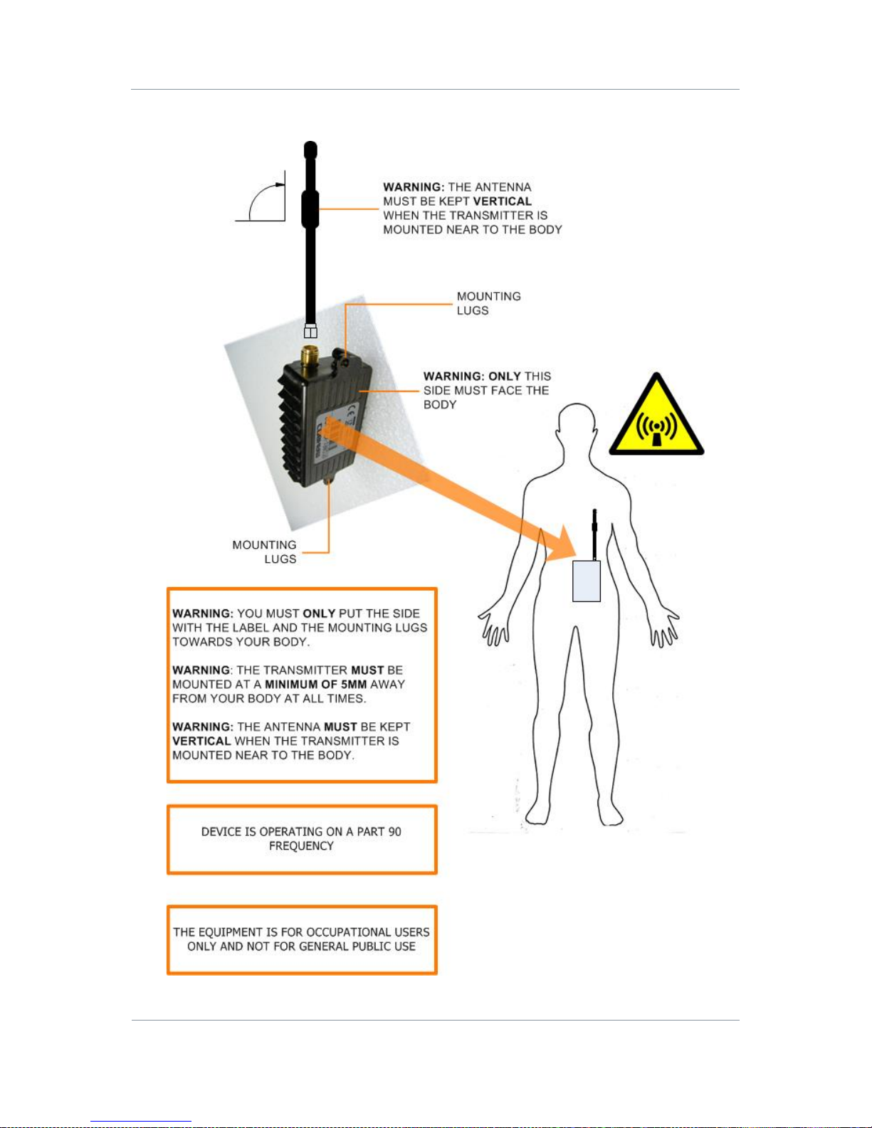
5.2 Wearing the Nano Transmitter on your Body
Figure 5-1 Wearing the Nano Transmitter on your Body
Page 35

Solo7 Nano Transmitter
Commercial in
Confidence
Video, Transmitters, Solo7 Nano
Transmitter
100145
Revision: 8.0
Commercial in
Confidence
Page 6-28
6. Advanced Operation
6.1 About Encryption
The target is focused on intercepting your radio signal. To do this, all that they need is a
radio receiver that oper ates in the same mode and on the same frequency you are using to
transmit. The mere fact that you are operating gives them valuable information. It tells them
that you are in the area and by the number of stations operating on the same frequency
they can estimate the size of the operation against them. If your radio net is operating in the
clear, the target specialists can see or hear exactly what is being transmitted for even more
information. When analysing the traffic patterns, the target can work out which station is the
net control station and identify the headquarters.
6.2 Setting up Encryption
If the AES scrambling option has been purchased for the SOLO system in use, then it is
possible to encrypt the link. Both AES128 and AES256 are licence-controlled features. You’ll
need to encrypt the traffic leaving the transmitter and set up the receiver for decrypt.
Before you Beg in
You’ll need:
A fully powered Nano Transmitter
The correct license loaded on the Nano Transmitter for the Encryption you want to use.
A PC connected to the Nano Transmitter with the latest Nano Transmitter Control
Application open.
Step 1: Select the Encryption Mode
1. In the Encryption Mode drop-down box select an encryption type. (AES128 for
example).
Step 2: Change the Encryption Key
The encryption key is a 128bit value for AES128 and a 256bit value for AES256, and is
entered as 32 or 64 ASCII hexadecimal characters (0..9, A..F).
1. Click the Encryption Key Entry button (the blue key).
2. The Encryption Key Entry dialog box open s.
3. Ensure the Encryption mode box is displaying the Encryption Mode you set in Step 1. If
not, set it now.
4. In the <Mode> key text b ox , typ e the encrypt i on key you want to use.
5. When you have entered the key, click the Check Mark.
6. Click the Apply button.
7. You’ll see the Setting Encryption Keys message, then your encryption is set.
Page 36

Solo7 Nano Transmitter
Commercial in
Confidence
Video, Transmitters, Solo7 Nano
Transmitter
100145
Revision: 8.0
Commercial in
Confidence
Page 6-29
Screenshot: Setting up Encryption
Figure 6-1 Setting up Encryption
Page 37
Solo7 Nano Transmitter
Commercial in
Confidence
Video, Transmitters, Solo7 Nano
Transmitter
100145
Revision: 8.0
Commercial in
Confidence
Page 6-30
Remarks
In our example above we used ABS encryption. ABS was the only item in the list because
this Nano Transmitter is not licenced for AES128 or AES256.
ABS needed a key of eight characters. If we had chosen AES256 for example, it would need
a 64 character key which we spread over two fields.
Key Type
Number of Characters Needed
ABS
8
AES128
32
AES256
64 (32 in each field)
Page 38
Solo7 Nano Transmitter
Commercial in
Confidence
Video, Transmitters, Solo7 Nano
Transmitter
100145
Revision: 8.0
Commercial in
Confidence
Page 6-31
6.3 About High Linearity and Low Power Modes
CAUTION: The combination of 100mW output power and High Linearity Mode must only be
used with additional cooling, either extra heat sinking or a fan.
The SOLO7 Nano Transmitter has two modes of operation:
Low Power Mode
High Linearity Mode
6.3.1 Low Power Mode
Low Power Mode optimises DC power consumption but to do this it must compromise the
quality of the COFDM waveform ‘shoulders’. This compromising of the shoulders often makes
little difference operationally when you just need to get a short range link in a reasonable RF
environment.
What Low Power Mode
does
do however is save a considerable amount of power so you can
deploy a unit on batteries for extended times.
Take a look at these power consumption figures when in Low Power Mode:
RF Output Power
VHF / UHF
L-Band
S-Band
10mW
3.1W
3.3W
3.4W
50mW
3.4W
3.6W
3.7W
100mW
3.7W
3.9W
4W
Table 6-1 – Typical Power Consumption in Low Power Mode
6.3.2 High Linearity Mode
High Linearity Mode optimises the quality of the COFDM waveform ‘shoulders’ , but to do
this it must increase DC power consumption.
This mode can be very useful when you are using an external amplifier which always expects
very high quality shoulders to work at its best.
Also, in busy RF environments y ou’ll need excellent shoulders to reject adjacent channel
interference.
Take a look at these charts to make a comparison between the modes:
DC Power
RF Power Out
Current I(mA)
Mode
Wattage
10
20
395
Low
3.95
10
17
330
Low
3.30
10
10
300
Low
3.00
10
20
455
High
4.55
Page 39
Solo7 Nano Transmitter
Commercial in
Confidence
Video, Transmitters, Solo7 Nano
Transmitter
100145
Revision: 8.0
Commercial in
Confidence
Page 6-32
DC Power
RF Power Out
Current I(mA)
Mode
Wattage
10
17
380
High
3.80
10
10
320
High
3.20
Table 6-2 – Typical Power Consumption 1650 to 2400MHz (High L and S-Band)
DC Power
RF Power Out
Current I(mA)
Mode
Wattage
10
20
390
Low
3.90
10
17
355
Low
3.55
10
10
325
Low
3.25
10
20
465
High
4.65
10
17
375
High
3.75
10
10
340
High
3.40
Table 6-3 – Typical Power Consumption 200 to 300MHz (VHF)
6.3.3 About DC Power Use
SOLO7 Nano Transmitter is very power efficient. In earlier models of transmitter, if you
switched from high to low RF power, the same DC power level would be used, although the
RF signal was attenuated.
In these newer transmitters, when you select lower RF powers the DC power level is
dropped too, using just the power ne eded to achieve the RF power required.
This stepping down of the DC power level applies to both Low Power Mode and High
Linearity Mode.
Page 40

Solo7 Nano Transmitter
Commercial in
Confidence
Video, Transmitters, Solo7 Nano
Transmitter
100145
Revision: 8.0
Commercial in
Confidence
Page 7-33
7. Advanced Setup
7.1 About Advanced Setup
To get the most from your radio system you must customise the programming for your
operations and area.
CAUTION: Before you start programming your radio make sure the batteries are fresh and
fully charged. If the radio loses power while you program it, its memory might be corrupted
which will require you to reset defaults. All information programmed in the radio might be
lost. Alternatively, you could use an AC adapter to power your radio.
The Nano Transmitter uses the Nano TX Controller software running on your PC which
enables you to perform many configuration tasks quickly and easily. These next topics tell
you how to connect your PC to the Nano Transmitter and then use your Nano TX Controller
to configure the unit.
IMPORTANT NOTE FOR HD NANO TX USERS: The newly released "Cobham Device
Controller" is required for control. This supersedes the Nano TX specific controller and can be
used for both.
7.2 Installing the Nano TX Controller on your PC
Before you Begin
You’ll need:
A PC running Windows XP or better.
The PC needs to have a spare USB port.
A copy of the Nano TX Controller software.
Note: You can download the latest version of the Controller from the Cobham Website.
Step 1: Install the Controller on your PC
1. The Installer package is called: NanoTXController.exe. Double-click this file.
2. The Nano TX Controller software will be installed on your PC.
Next Steps
Connect the Nano Transmitter to your PC using a Serial Connection.
7.3 Connecting your PC to the Nano TX using Serial
Before you Beg in
You’ll need:
A Personal Computer with the Nano TX Controller Application installed.
Page 41
Solo7 Nano Transmitter
Commercial in
Confidence
Video, Transmitters, Solo7 Nano
Transmitter
100145
Revision: 8.0
Commercial in
Confidence
Page 7-34
A USB Type A to USB Micro-B Cable.
A powered Nano Transmitter unit.
Step 1: Install the Nano TX Controller on your PC
Ensure you have installed the Transmitter Control Application onto your Personal
Computer. You can download the latest version of this software from the Cobham website.
Step 2: Connect to your Personal Computer using Serial (RS232)
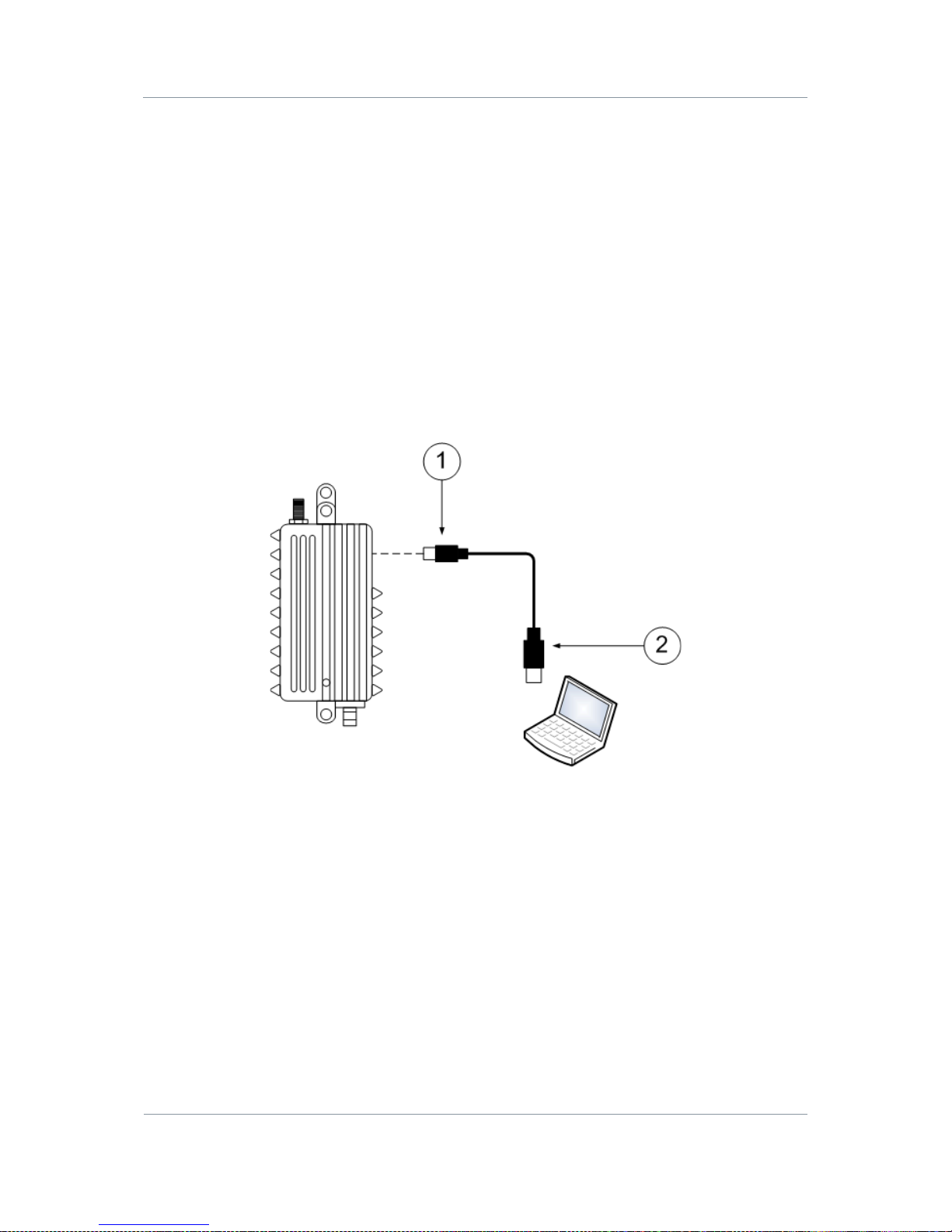
1. Connect the USB Micro-B 4-way plug (pin) on the Control Cable to the USB Micro-B 4-
way receptacle (socket) on the Nano Transmitter .
2. Now connect the USB Type A 4-way p lug (pin) to the USB receptacle (socket) on your
personal computer.
Diagram: Nano Transmitter Serial Connection
Figure 7-1 Nano Transmitter Serial Connection
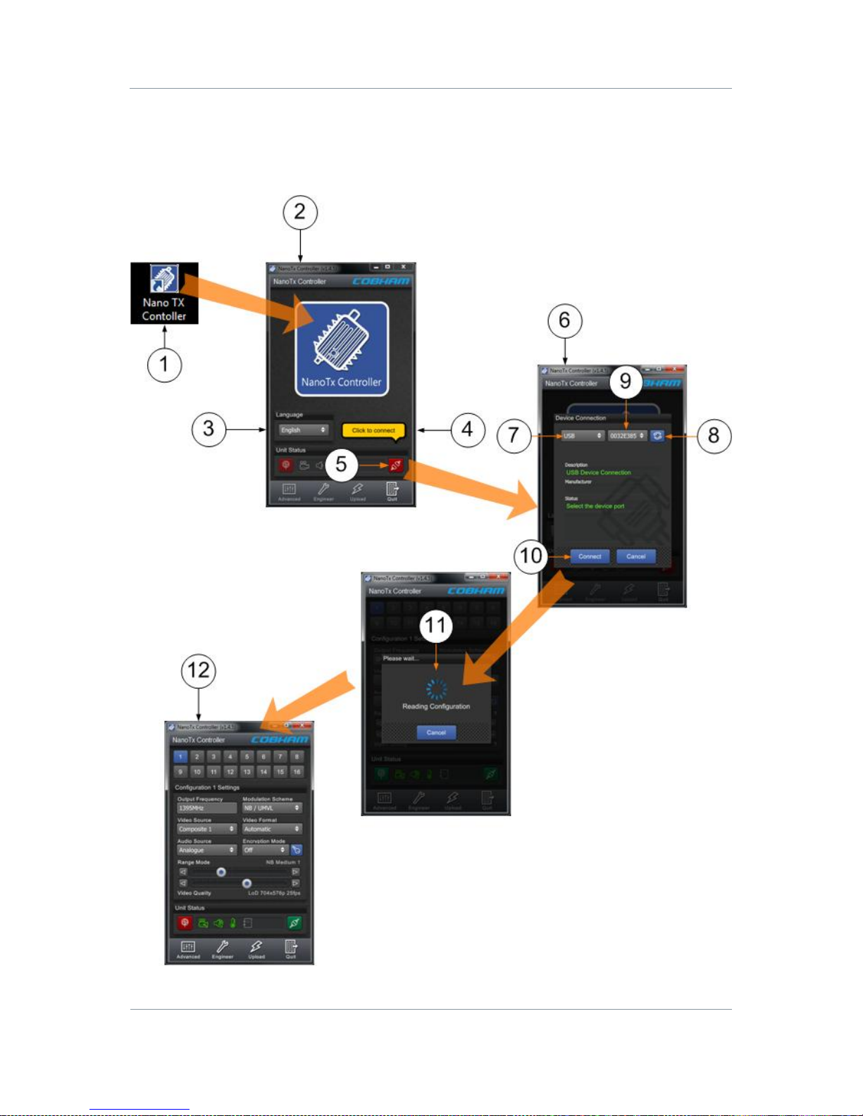
Step 3: Start the Nano TX Controller
1. Double-click the Nano TX Controller icon on the computer desktop.
2. The Nano TX Controller opens.
3. From the Language box, select the Language you want to use.
4. You’ll see the Click to Connect message.
5. Click the Connect button.
6. The Device Connection Window opens.
7. Select USB.
8. Click the Refresh button.
9. You’ll see the Identification Number of the Nano Transmitter’s USB interface.
Page 42
Solo7 Nano Transmitter
Commercial in
Confidence
Video, Transmitters, Solo7 Nano
Transmitter
100145
Revision: 8.0
Commercial in
Confidence
Page 7-35
10. Click the Connect button.
11. The Nano TX Controller main window opens.
Screenshot: Start the Nano TX Controller
Page 43
Solo7 Nano Transmitter
Commercial in
Confidence
Video, Transmitters, Solo7 Nano
Transmitter
100145
Revision: 8.0
Commercial in
Confidence
Page 7-36
Figure 7-2 Start the Nano TX Controller
Next Steps
Explore the Main Window.
7.4 Exploring the Nano TX Controller Main Window
Before you Beg in
You’ll need:
To have connected your PC to the Nano Transmitter using Serial.
To have established a serial connection. (Green Connect button showing).
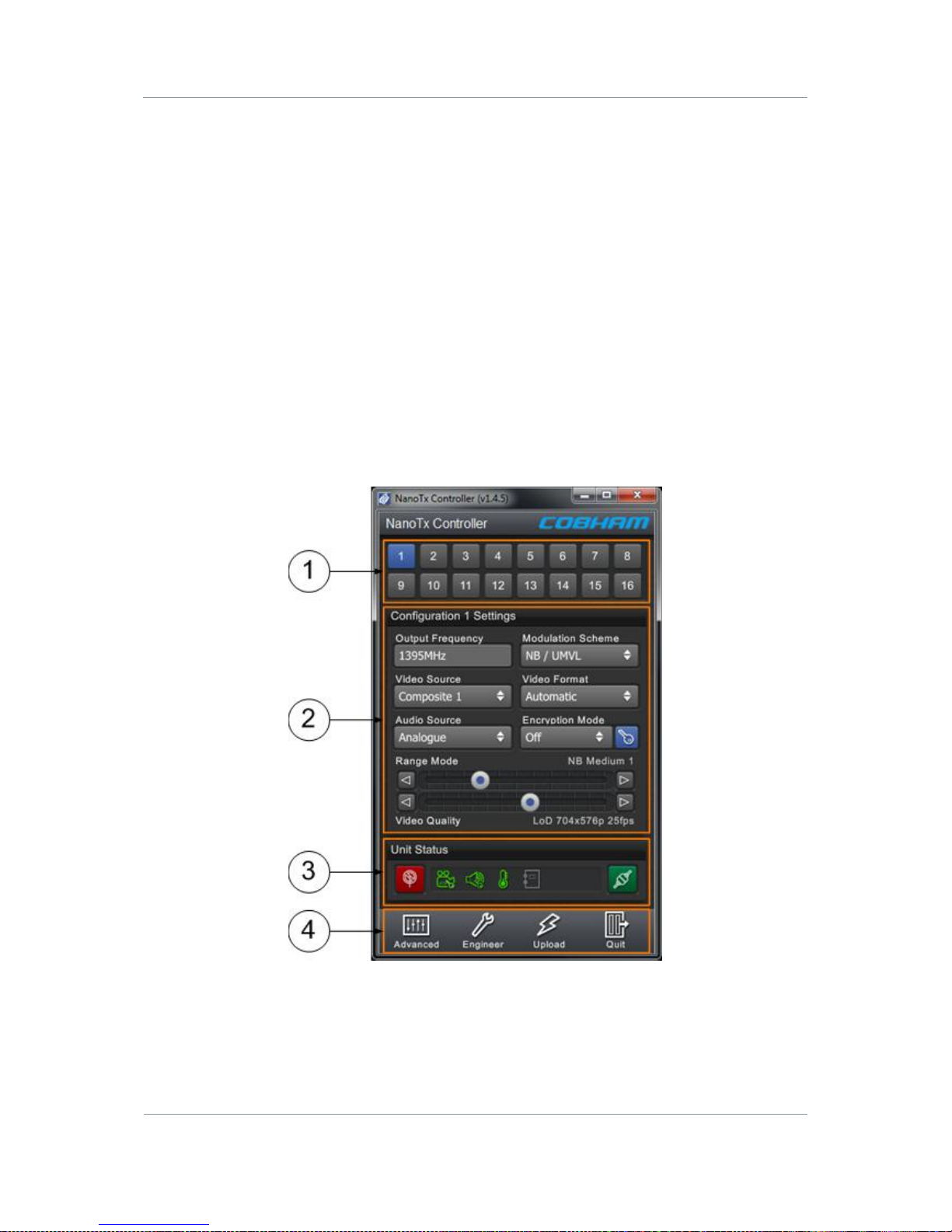
Screenshot: Explore the Nano TX Controller Main Window
Figure 7-3 Explore the Nano TX Controller Main Window
Page 44
Solo7 Nano Transmitter
Commercial in
Confidence
Video, Transmitters, Solo7 Nano
Transmitter
100145
Revision: 8.0
Commercial in
Confidence
Page 7-37
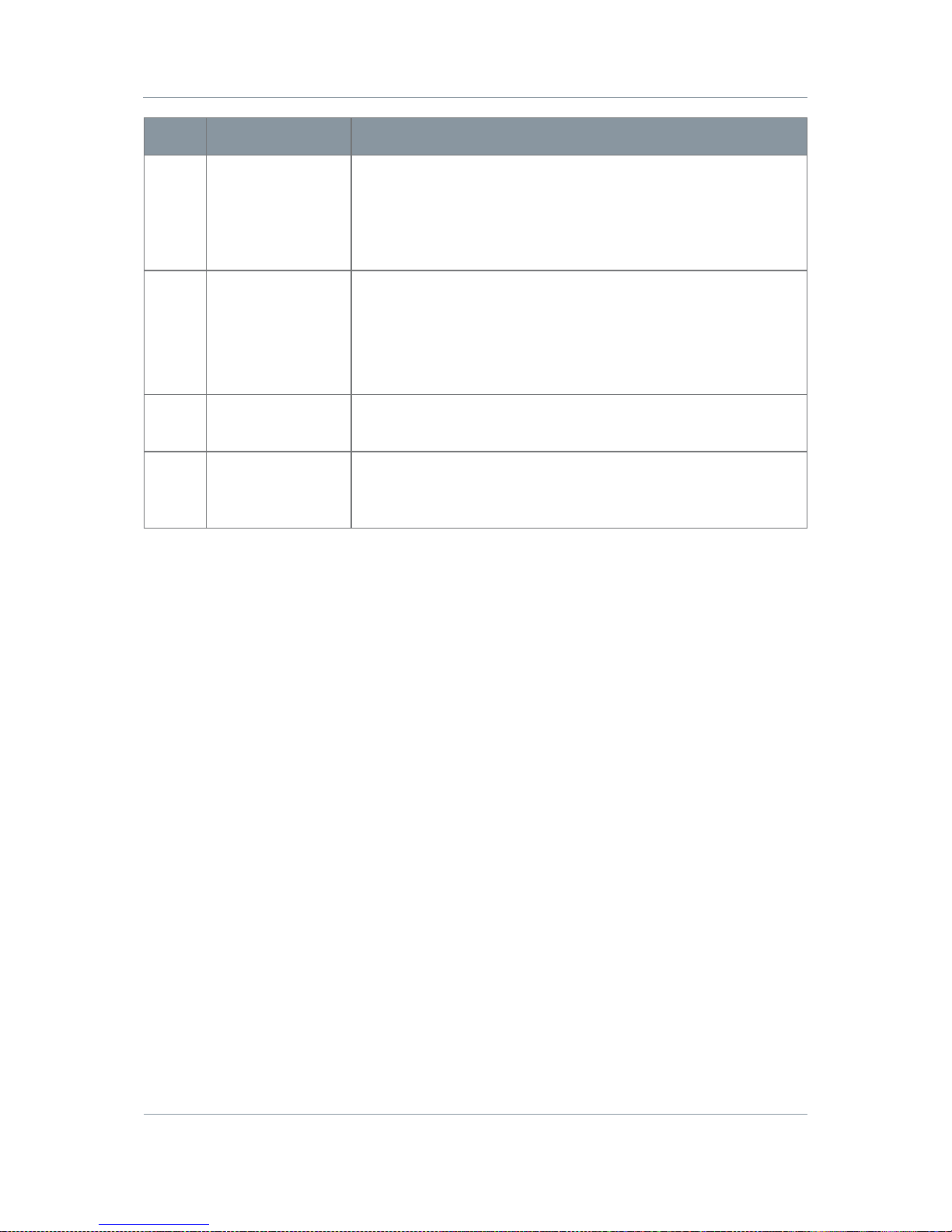
No
Name
Notes
1
Configuration
Buttons.
Sixteen (or eight) configurations can be stored. The Blue
button is the currently active configuration. You can set up
just one of them if you want but it can be very useful to have
all 16 populated. Try having different frequencies and range
settings available.
2
Basic Settings for
the Active
Configuration
When you have selected a configuration button above, this
section shows the core settings for that configuration. These
are repeated in the Advanced window along with many more
settings.
You can edit these settings r i ght here to make quick changes.
3
Unit Status Panel
A group of indicators to report things like: RF Status, Video
Lock, Audio Lock, Temperature and Connection Status.
4
Switch Panel
Buttons to take you to: The Advanced window, the Engineer
window, the Upload window and to quit the Nano TX
Controller.
Table 7-1 – Control Application Main Wi nd ow Key
7.5 Performing a Quick Setup
There are several basic setup fields that enable you to do a quick setup of the unit without
getting into fine detai ls. (We’ll meet those later).
Before you Beg in
You’ll need:
To have connected your PC to the Nano Transmitter using Serial.
To have established a serial connection. (Green Connect button showing).
Step 1: Choose a Configuration
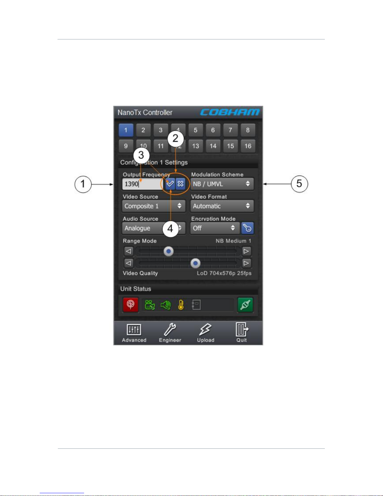
1. Click one of the sixteen configuration buttons.
2. You’ll see the Reading Configuration message.
3. The button is illuminated in blue and the Configuration Settings are ready to edit.
Step 2: Work with the Configuration Settings
1. Click one of the Configuration Settings boxes.
2. The box turns white and check mark and cross butt o ns appear.
3. When you start to edit, the check mark butt on becomes active (shaded in blue).
Page 45
Solo7 Nano Transmitter
Commercial in
Confidence
Video, Transmitters, Solo7 Nano
Transmitter
100145
Revision: 8.0
Commercial in
Confidence
Page 7-38
4. When you have completed your edit, click the check mark button to accept the change
or click the cross button to discard the change.
5. This technique applies to any drop-down box you’ll edit on Nano TX Controller.
Screenshot: Work with the Configuration Settings
Figure 7-4 Work with the Configuration Settings
Page 46

Solo7 Nano Transmitter
Commercial in
Confidence
Video, Transmitters, Solo7 Nano
Transmitter
100145
Revision: 8.0
Commercial in
Confidence
Page 7-39
Step 3: Perform a Basic Configuration Setting
Basic Setting
Options
Notes
Output frequency
(MHz)
Any frequency in the range
of the unit.
A SOL7NTX-100150 for
example can use
frequencies from 1.00GHz
to 1.50GHz.
Type in the frequency that you want
this device to use in megahertz (MHz).
If you type in a frequency which is out
of range, the unit will automatically
round to the highest or lowest
frequency which actually is available.
The transmitter frequency can be set in
step sizes of 125kHz.
Video Source
Off
Composite 1
Composite 2
S-Video
HD Nano TX Only:
SDI (DIN 1.0/2.3
receptacle)
HDMI (Micro HDMI Type D
receptacle).
With the conventional Omnetics Tri-
Lobe Latching AV cable, there is o n e
yellow RCA Phono plug for Video input.
This is Composite 1.
The generic Omnetics 9-way Breakout
accessory cable can be used to access
two video inputs. Here’s how you can
use them:
For Composite Video, you can use
one or the other (but not both at the
same time).
Video 1: Composite 1 Input.
Video 2: Composite 2 Input.
For S-Video, you’ll use both like this:
Video 1: S-Video Luma Input.
Video 2: S-Video Chroma Input.
You can switch video off, leaving all the
bandwidth available for audio and data.
Audio Source
Off
Analogue
Differential
You can switch audio off, leaving all the
bandwidth available for video and data.
Analogue – When selected the audio
input cable can be used for mono left,
mono right or stereo pair.
Differential – When selected the audio
input cable can be used as a differential
pair for long cable runs on high quality
microphones (mono only).
Modulation
Scheme
NB / UMVL
DVB-T
This box enables you to select
Cobham’s Narrowband / UMVL
modes (NB / UMVL) or DVB-T.
Page 47

Solo7 Nano Transmitter
Commercial in
Confidence
Video, Transmitters, Solo7 Nano
Transmitter
100145
Revision: 8.0
Commercial in
Confidence
Page 7-40
Basic Setting
Options
Notes
Video Format
Automatic
PAL
NTSC
NTSC NP
HD Nano TX Only:
720p50, 720p59, 720p60,
1080i50, 1080i59, 1080i60,
1080p23, 1080p24,
1080p25, 1080p29,
1080p30, 1080psf23,
1080psf24, 1080psf25,
1080psf29, 1080psf30.
Select the Video format that matches
the camera you are using.
Alternatively the Automatic setting
enables the Nano TX to determine if
the signal is PAL or NTSC automatically.
Power up standard in Automatic mode
defaults to PAL. This can be changed
by setting the input to NTSC NP for
example and then back to Automatic.
Encryption Mode
Off
ABS
AES128
AES256
In this drop-down you’ll see a list of
Encryption Modes available on this unit.
All Nano Transmitters have ABS but the
AES modes are all license dependant. If
you are not licenced for AES128, you
won’t see it in this list.
Select the Encryption Mode you want to
use or choose off to transmit in clear.
Encryption Key
Opens the Encryption Key
Entry dialog.
Check the Encryption mode is co rrect
(you can change it here if required) and
then enter your Key.
ABS=8 characters
AES=32 characters
AES=64 characters
Must be: ASCII hexadecimal characters
(0..9, A..F).
Page 48

Solo7 Nano Transmitter
Commercial in
Confidence
Video, Transmitters, Solo7 Nano
Transmitter
100145
Revision: 8.0
Commercial in
Confidence
Page 7-41
Basic Setting
Options
Notes
Range Mode
Custom
NB Short 1
NB Short 2
NB Medium 1
NB Medium 2
NB Long 1
NB Long 2
NB ULong 1
NB ULong 2
NB XLong 1
NB XLong 2
UMVL Short 1
UMVL Short 2
UMVL Medium 1
UMVL Medium 2
UMVL Long 1
UMVL Long 2
DVB-T XShort 1
DVB-T XShort 2
DVB-T Short 1
DVB-T Short 2
DVB-T Medium 1
DVB-T Medium 2
DVB-T Medium 3
DVB-T Long 1
DVB-T Long 2
DVB-T Long 3
Move the slider towards the left to get
shorter ranges but higher picture and
audio quality.
Move the slider to the right to increase
the range but reduce the picture and
audio quality.
Custom enables you to make up your
own setting which we’ll look at later.
NB types apply when you have select ed
the Narrowband Modulation scheme.
UMVL types apply when you have
selected the UMVL Modulation s ch em e.
DVB-T types apply when you have
selected the DVB-T Modulation scheme.
Page 49
Solo7 Nano Transmitter
Commercial in
Confidence
Video, Transmitters, Solo7 Nano
Transmitter
100145
Revision: 8.0
Commercial in
Confidence
Page 7-42
Basic Setting
Options
Notes
Video Quality
LoD 176x144p 25fps
LoD 176x288p 25fps
LoD 352x288p 25fps
LoD 352x576i 25fps
LoD 470x576i 25fps
LoD 528x576i 25fps
LoD 704x576p 25fps
StD 704x576p 25fps
StD 704x576p 12fps
StD 704x576p 6fps
StD 704x576p 3fps
StD 704x576p 1fps
These settings taken with
Range Mode set to NB
Medium 1 and Video Format
at PAL. They will be
different for other Range
Modes and Video Formats.
The centre point corres ponds to our
recommended compromise for the
current available bandwidth or range
mode.
Move the slider to the left to get lower
resolution at a higher frame rate.
Move the slider to the right to get
higher resolution at a lower frame rate.
LoD=Low Delay
ULoD=Ultra Low Delay
StD=Standard Delay
Fps=Frames per second 25 for PAL, 30
for NTSC.
P=Progressive
I=Interlace
Table 7-2 – Perform a Basic Configuration Setting
Note-1: Some Modulation Schemes are licensed features. If you are not licensed for
these modes you will not be able to select them.
Check Advanced Settings > Unit to see your licence status.
Unlicensed features in option lists are marked with a padlock icon.
Note-2: Some encryption modes are licensed features. If you are not licensed for these
modes you will not be able to see them in the Encryption Mode list.
Check Advanced Settings > Unit to s ee your l icence status.
7.6 Working with the Unit Status Panel
Before you Beg in
You’ll need:
To have connected your PC to the Nano Transmitter using Serial.
To have established a serial connection. (Green Connect button showing).
Page 50
Solo7 Nano Transmitter
Commercial in
Confidence
Video, Transmitters, Solo7 Nano
Transmitter
100145
Revision: 8.0
Commercial in
Confidence
Page 7-43
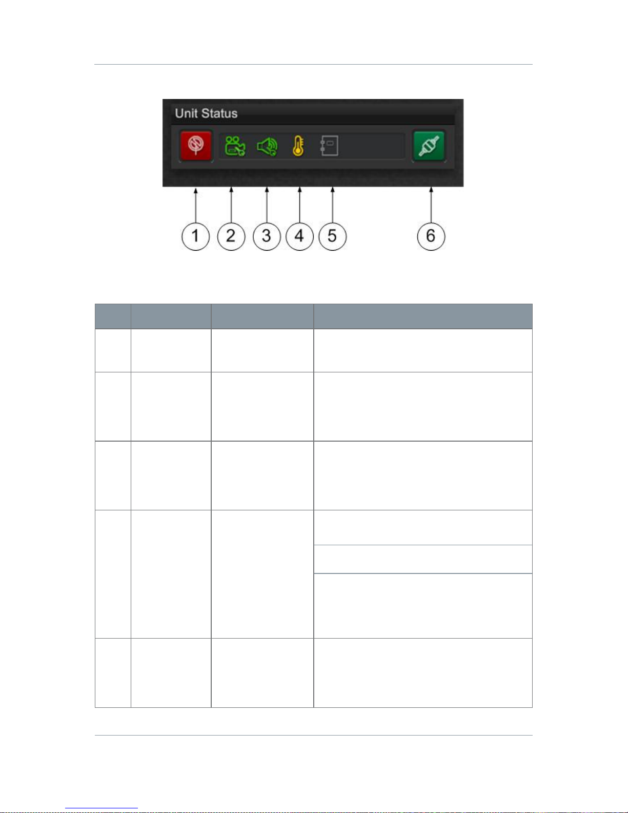
Screenshot: The Unit Status Panel
Figure 7-5 The Unit Status Panel
Step 1: Interpret the Toolbar
No
Name
Options
Notes
1
RF Button
Red=RF Off
Green=RF On
Click to toggle RF on or Off.
2
Video Lock
Red=Unlocked
Green=Locked
Tells you if the unit has successfully locked
to the video source.
Unlocked will also be shown if video is
disabled.
3
Audio Lock
Red=Unlocked
Green=Locked
Tells you if the unit has successfully locked
to the audio source.
Unlocked will also be shown if audio is
disabled.
4
Temperature
Green Symbol
Yellow Symbol
Red Symbol
An indication of the temperature of the
FPGA. Attempt to keep it green.
CAUTION: If it changes to red, switch the
unit off and allow it to cool.
0 to 59 degrees Celsius shown in green.
60 to 84 degrees Celsius shown in yellow.
85 degrees Celsius or above show n i n r ed.
5
Logging
Dimmed-
Unavailable
White-Logging
running
Logging is normally off by default.
Logging is enabled by using a command
line switch which is fully described in
Appendix D,
Reference Material
.
Page 51
Solo7 Nano Transmitter
Commercial in
Confidence
Video, Transmitters, Solo7 Nano
Transmitter
100145
Revision: 8.0
Commercial in
Confidence
Page 7-44
No
Name
Options
Notes
6
Connect
Button
Red=Disconnected
Green-Connected
Click to toggle Serial Connection.
Indicates the status of the serial connection
between the Nano TX Controller software
on your PC and the Nano Transmitter.
You must be connected to control the unit.
Table 7-3 – Unit Status Panel Key
7.7 Working with the Switch Panel
Before you Beg in
You’ll need:
To have connected your PC to the Nano Transmitter using Serial.
To have established a serial connection. (Green Connect button showing).
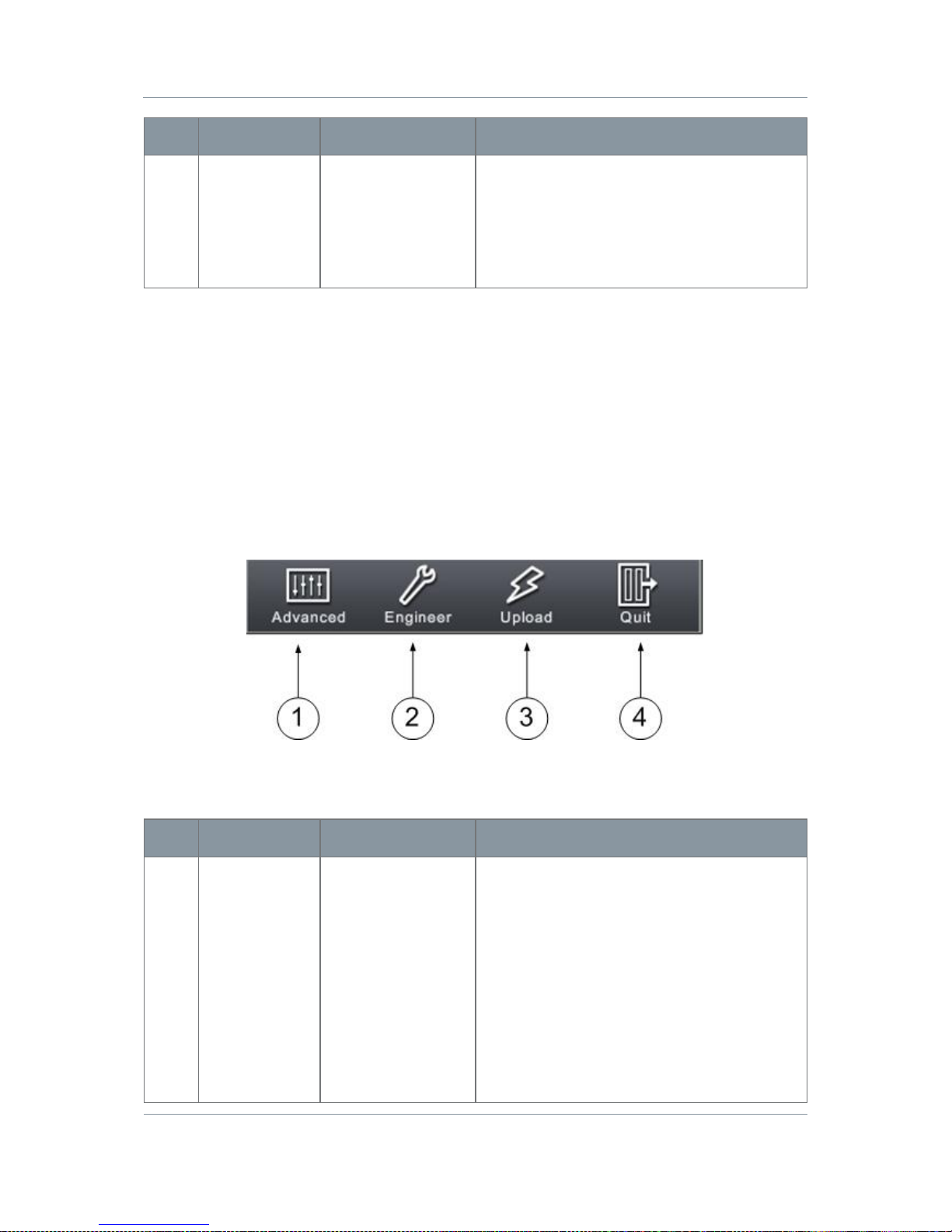
Screenshot: The Switch Panel
Figure 7-6 The Switch Panel
Step 1: Interpret the Switch Panel
No
Name
Options
Notes
1
Advanced
Click to open the
Advanced Window.
The Back Button
will always return
you to the Main
Window.
The Advanced Window gives access to
five windows:
Unit – Software versions, licens e s etc.
Modulation – Frequency, power, FEC etc.
Audio – Audio source, sample rate etc.
Video – Video source, format etc.
Misc – Data settings etc.
The Advanced Windows are fully described
later.
Page 52

Solo7 Nano Transmitter
Commercial in
Confidence
Video, Transmitters, Solo7 Nano
Transmitter
100145
Revision: 8.0
Commercial in
Confidence
Page 7-45
No
Name
Options
Notes
2
Engineer
Click to open the
Engineering
Options window.
The Back Button
will always return
you to the Main
Window.
This gives access to the diagnostic pane
where you can send serial commands direct
to the unit and get results back. This pane
is designed advanced users.
The Engineering Options are fully described
in Appendix D,
Reference Material
.
3
Upload
Click to open the
Upload File
window.
The Back Button
will always return
you to the Main
Window.
This gives access to the Upload File
window where you can upgrade your
license files to get more features or
upgrade your firmware to the latest versio n.
This procedure is fully described in
Appendix D,
Reference Material
.
4
Quit
Click to quit the
Nano TX Controller
application.
You’ll see a Confirmation message box.
Click OK button to really quit or Cancel to
return to the application.
Table 7-4 – Switch Panel Key
7.8 Working with the Unit Tab
Before you Beg in
You’ll need:
To have connected your PC to the Nano Transmitter using Serial.
To have established a serial connection. (Green Connect button showing).
Step 1: Open the Advanced Window > Unit Tab
1. On the Main Window in the Switch Panel, click the Advanced button.
2. Click the Unit Tab.
Page 53
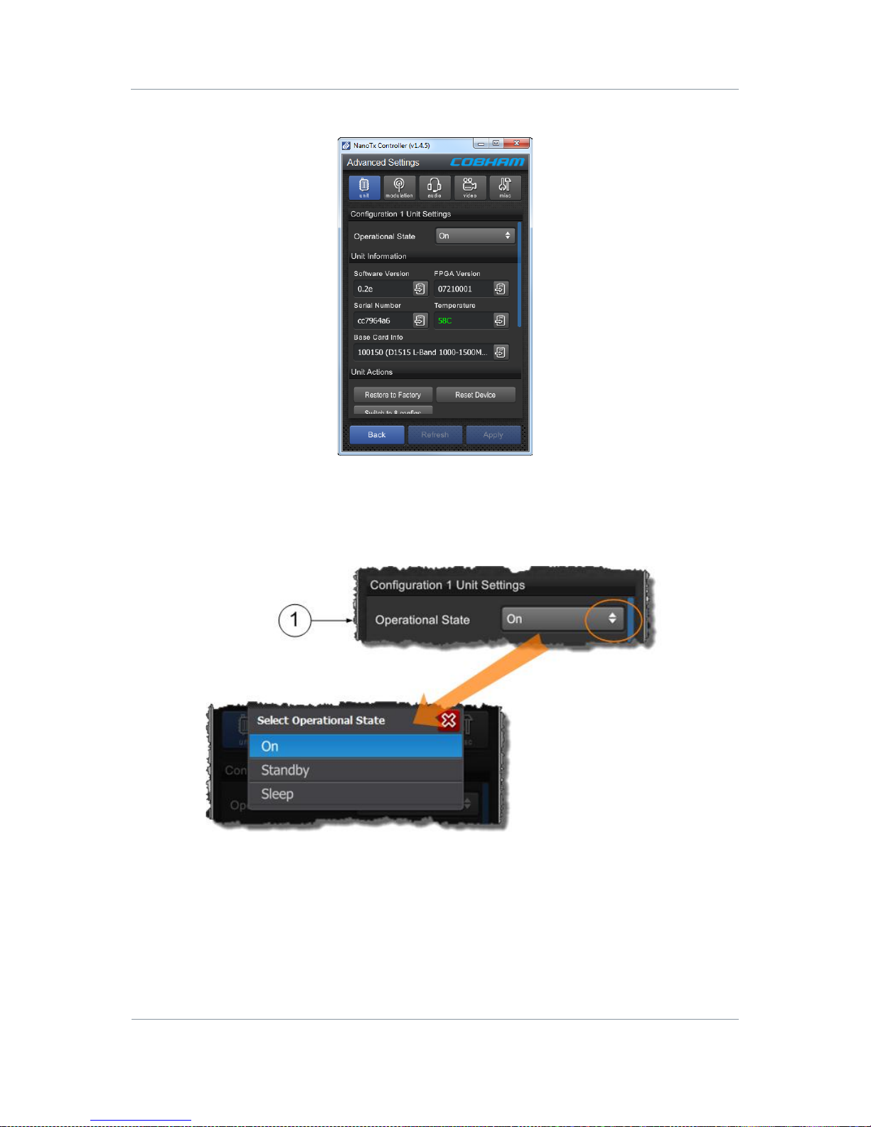
Solo7 Nano Transmitter
Commercial in
Confidence
Video, Transmitters, Solo7 Nano
Transmitter
100145
Revision: 8.0
Commercial in
Confidence
Page 7-46
Screenshot: Unit Tab
Figure 7-7 Unit Tab
Step 2: Configure the Unit Settings
Screenshot: Unit Settings
Page 54
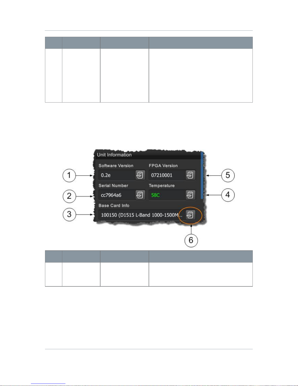
Solo7 Nano Transmitter
Commercial in
Confidence
Video, Transmitters, Solo7 Nano
Transmitter
100145
Revision: 8.0
Commercial in
Confidence
Page 7-47
No
Name
Options
Notes
1
Operational
State
On
Standby
Sleep
On – The unit is fully powered and in an
operational state.
Standby – The unit is using less power but
can be brought back to operation rapidly.
Sleep – The unit is consuming the least
amount of power but needs to be woken
before being able to operate fully.
Table 7-5 – Unit Settings Key
Step 3: Configure the Unit Information Settings
Screenshot: Unit Information Settings
No
Name
Options
Notes
1
Software
Version
0.2e or any valid
software release
number.
This is the version of the firmware running
on the board. We may ask you for this
during a support call.
Page 55

Solo7 Nano Transmitter
Commercial in
Confidence
Video, Transmitters, Solo7 Nano
Transmitter
100145
Revision: 8.0
Commercial in
Confidence
Page 7-48
No
Name
Options
Notes
2
Serial Number
cc7964a6
The Electronic Serial Number of the unit.
We may ask you for this during a support
call.
The licence file is specially configured to
only work with a device that has a
matching Electronic Serial Number. This
means the licence can only be used with
the actual hardware device for which it is
intended.
3
Base Card Info
100150 (D1515 L-
Band 10001500MHz).
The frequency band details for the RF card
in the unit. See
Getting Started, Identifying
the Variants
for more versions.
4
Temperature
Any temperature in
degrees Celsius.
0 to 59 shown in green.
60 to 84 shown in yellow.
85 or above shown in red.
An indication of the temperature of the
FPGA. Attempt to keep it green.
CAUTION: If it changes to red, switch the
unit off and allow it to cool.
5
FPGA Version
07210001 or any
valid version
number.
The version of FPGA firmware currently
running on the D1500 board. We may ask
for this number during a support call.
6
Copy to
Clipboard
Button
Click to copy
contents of the
field to your
Windows clipboard.
If you need to gather some data about the
unit these buttons make it simple to get a
copy of the field onto your clipboard. Then,
you can paste it into a Word document for
example. You’ll find these buttons on most
fields in the Nano TX Controller.
Table 7-6 – Unit Information Settings Key
Page 56
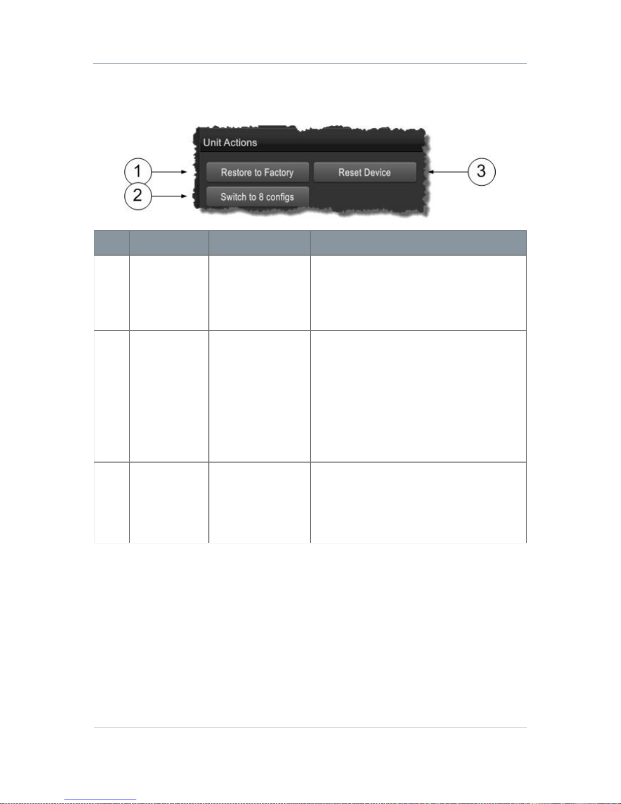
Solo7 Nano Transmitter
Commercial in
Confidence
Video, Transmitters, Solo7 Nano
Transmitter
100145
Revision: 8.0
Commercial in
Confidence
Page 7-49
Step 4: Configure the Unit Actions Settings
Screenshot: Unit Actions Settings
No
Name
Options
Notes
1
Restore to
Factory Button
Click to Restore
factory settings.
If you have been working on a complex
setup and need to get back to a simple
setup, click Restore to Factory. The unit will
put all parameters back to a default know
state from where you can start again.
2
Switch to 8 /
16 Configs
Button
Click to toggle
between 8 and 16
configurations.
It is possible to toggle the unit into eight
configurations mode instead of sixteen.
You’ll see the Confirmation warning
message. Click the OK button if you are
sure, Cancel returns you to the previous
menu.
Some options are stored on a global or
configuration basis depending on the
number of configurations used.
3
Reset Device
Click to reset.
This performs a power cycle on t he d e vice.
You’ll see the Confirmation warning
message. Click the OK button if you are
sure, Cancel returns you to the previous
menu.
Table 7-7 – Unit Action Settings Key
Page 57
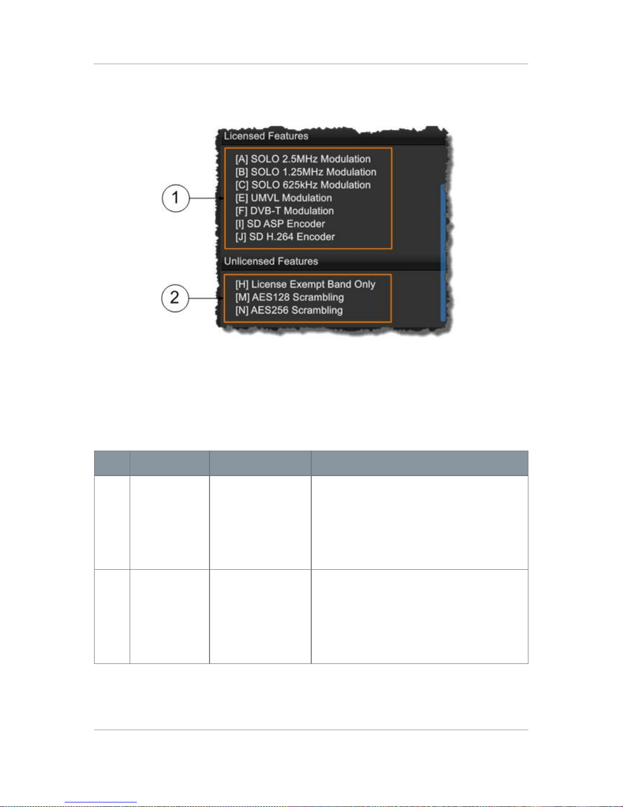
Solo7 Nano Transmitter
Commercial in
Confidence
Video, Transmitters, Solo7 Nano
Transmitter
100145
Revision: 8.0
Commercial in
Confidence
Page 7-50
Step 5: Interpret the Licensed Features Settings
Screenshot: Licensed Features Settings
No
Name
Options
Notes
1
Licensed
Features
Any license which
is available for the
Nano Transmitter.
Licenses are given letter codes in square
brackets [A] and a note of what that license
does, SOLO2.5MHz Modulation for example.
Codes shown in the Licensed Features
group box are loaded on your device and all
these features are available to use.
2
Unlicensed
Features
Any license which
is available for the
Nano Transmitter.
Codes shown in the Unlicensed Features
group box are available for the Nano
Transmitter, but have not been purchased
for your device yet.
To load new licenses see Appendix D,
Reference Material
.
Table 7-8 – Licensed F eat ures K ey
Page 58

Solo7 Nano Transmitter
Commercial in
Confidence
Video, Transmitters, Solo7 Nano
Transmitter
100145
Revision: 8.0
Commercial in
Confidence
Page 7-51
7.9 Working with the Modulation Tab
Before you Beg in
You’ll need:
To have connected your PC to the Nano Transmitter using Serial.
To have established a serial connection. (Green Connect button showing).
Step 1: Open the Advanced Window > Modulation Tab
1. On the Main Window in the Switch Panel, click the Advanced button.
2. Click the Modulation Tab.
3. Click and drag the scrollbar on the right of the screen to see the whole display.
Page 59
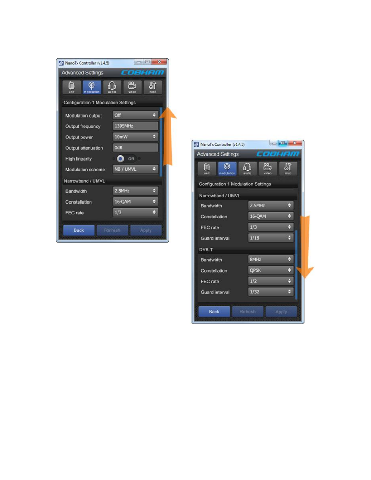
Solo7 Nano Transmitter
Commercial in
Confidence
Video, Transmitters, Solo7 Nano
Transmitter
100145
Revision: 8.0
Commercial in
Confidence
Page 7-52
Screenshot: Modulation Tab
Figure 7-8 Modulation Tab
Page 60
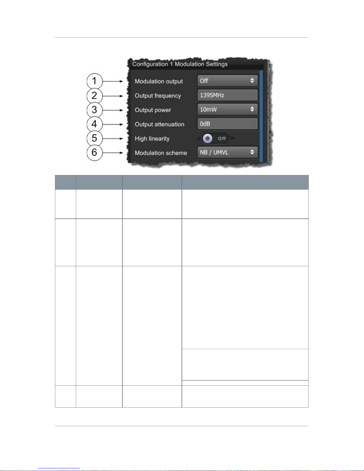
Solo7 Nano Transmitter
Commercial in
Confidence
Video, Transmitters, Solo7 Nano
Transmitter
100145
Revision: 8.0
Commercial in
Confidence
Page 7-53
Step 2: Configure the Modulation Settings
No
Name
Options
Notes
1
Modulation
Output
Off or On
Toggles the RF on or Off. Exactly repeats
the action of the RF Button on the Unit
Status panel on the Main Window.
2
Output
Frequency
UHF, L, S and C
Bands
Range dependant
on unit type and
licensing.
The frequency in megahertz (MHz) that you
want to use for this preset.
If you try to input a frequency that is out of
range, the radio will tune the nearest
available frequency automatically.
3
Output Power
10mW
50mW
100mW
Choose the power output you want to use
for your transmission. For short range
applications for example you may choose
low power to protect the receive r an d to
reduce the possibility of detection.
A lower power output will significantly lower
power consumption of the unit, increasing
battery life. The unit will also run cooler
which may be important for enclosed / body
worn applications.
CAUTION: The combination of 100mW
output power and high linearity must only
be used with additional cooling, either extra
heat sinking or a fan.
4
Output
Attenuation
0 to 31.75dB
0 to 31.75dB of attenuation can be applied
to the output of the transmitter.
Page 61
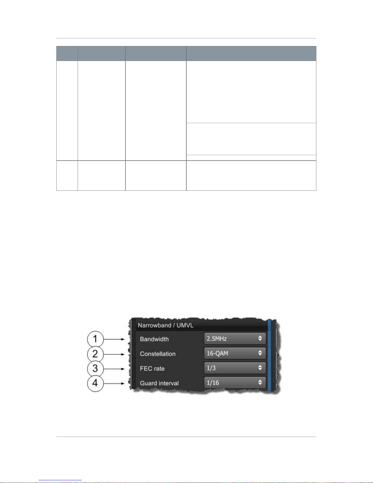
Solo7 Nano Transmitter
Commercial in
Confidence
Video, Transmitters, Solo7 Nano
Transmitter
100145
Revision: 8.0
Commercial in
Confidence
Page 7-54
No
Name
Options
Notes
5
High Linearity
Option Button
Blue=OFF
Orange=ON
When on, high linearity mode improves
shoulder performance by several dB at the
expense of power consumption.
Often used when working with power
amplifiers which expect excellent shoulder
performance to operate, or for improved
adjacent channel performance.
CAUTION: The combination of 100mW
output power and high linearity must only
be used with additional cooling, either extra
heat sinking or a fan.
6
Modulation
Scheme
NB /UMVL
DVB-T
This box enables you to select Cobham’s
Narrowband / UMVL modes (NB / UMVL)
or DVB-T.
Table 7-9 – Modulation Settings Key
Step 3a: Configure the NB /UMVL Settings
If you selected NB /UMVL for the Mod u l a tion scheme earlier, then these next settings need
to be configured.
If you selected DVB-T then see
Configure the DVB-T Settings
later.
Page 62

Solo7 Nano Transmitter
Commercial in
Confidence
Video, Transmitters, Solo7 Nano
Transmitter
100145
Revision: 8.0
Commercial in
Confidence
Page 7-55
No
Name
Options
Notes
1
Bandwidth
Narrowband:
2.5MHz
1.25MHz
625kHz
UMVL:
6MHz
7MHz
8MHz
Cobham Narrowband, Ultra-Narrowband
and Ultra-X modes provide excellent r a nge
and efficient use of available channel
bandwidth.
Cobham Ultra Mobile Video Link modes
provide higher data throughput than
Narrowband by using the same bandwidths
as DVB-T. UMVL will provide an advantage
over DVB-T at C/X-band in short range
mobile environments.
2
Constellation
QPSK, 16QAM,
BPSK and 8PSK
The COFDM constellation in use. On a
sliding scale:
16QAM-more user data, less robust, less
range.
QPSK
8PSK
BPSK-less user data, more robust, more
range.
3
FEC Rate
1/3 or 2/3
This field indicates the forward error
correction (FEC) rate which is being applied.
Think ‘data bits/all bits’
1/3 means 1 bit out of 3 bits is data and
therefore 2 bits are used for error
correction.
Little user data means less picture quality,
but more error correction means a more
robust signal and therefore more range.
2/3 means 2 bits out of 3 bits are data and
therefore 1 bit is used for error correction.
More user data means better picture
quality, but less error co rrection means less
robust signal and therefore less range.
Page 63
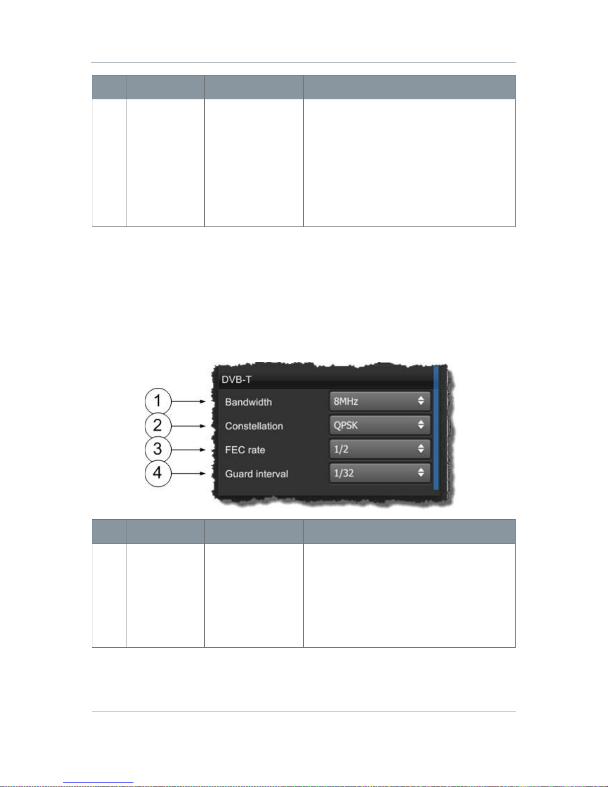
Solo7 Nano Transmitter
Commercial in
Confidence
Video, Transmitters, Solo7 Nano
Transmitter
100145
Revision: 8.0
Commercial in
Confidence
Page 7-56
No
Name
Options
Notes
4
Guard Interval
1/16 or 1/8
The guard interval which is being applied.
The guard interval is a deliberate extension
of the RF symbol period to give immunity to
reflections.
1/16, short extension, deals with fast
reflections, more data, less range.
1/8, long extension, deals with slower
reflections, less data, more range.
Table 7-10 – NB / UMVL Settings Key
Step 3b: Configure the DVB-T Settings
If you selected DVB-T for the Modula tion scheme earlier, then these next settings nee d to be
configured.
If you selected NB / UMVL then see
Configure the NB / UMVL Settings
previously.
No
Name
Options
Notes
1
Bandwidth
DVB-T:
6MHz
7MHz
8MHz
DVB-T modes provide excellent data
throughput but shorter range than Cobham
Narrowband modes.
Typically bandwidth requirements for DVB-T
depend on location and channel licensing.
User data rates and range also vary slight
between bandwidths.
Page 64

Solo7 Nano Transmitter
Commercial in
Confidence
Video, Transmitters, Solo7 Nano
Transmitter
100145
Revision: 8.0
Commercial in
Confidence
Page 7-57
No
Name
Options
Notes
2
Constellation
QPSK, 16QAM and
64QAM
The COFDM constellation in use.
QPSK-less user data, more robust, more
range.
16QAM-more user data, less robust, less
range. (link performance reduced by 5db)
64QAM-max user data, least robust, least
range.
3
FEC Rate
1/2, 2/3, 3/4, 5/6
and 7/8
The forward error correction (FEC) rate
which is being applied to the DVBT mode in
use.
Think ‘data bits/all bits’
1/2 means 1 bit out of 2 bits is data and
therefore 1 bit is used for error correction.
Little user data means less picture quality,
but more error correction means a more
robust signal and therefore more range.
7/8 means 7 bits out of 8 bits are data and
therefore 1 bit is used for error correction.
More user data means better pi cture
quality, but less error correcti o n mea ns less
robust signal and therefore less range.
4
Guard Interval
1/32, 1/16, 1/8
and 1/4
The guard interval which is being applied to
the DVBT mode in use.
The guard interval is a deliberate extension
of the RF symbol period to give immunity to
reflections.
1/32, short extension, deals with fast
reflections, more data, less range.
1/4, long extension, deals with slower
reflections, less data, more range.
Table 7-11 – DVB-T Settings Key
Page 65
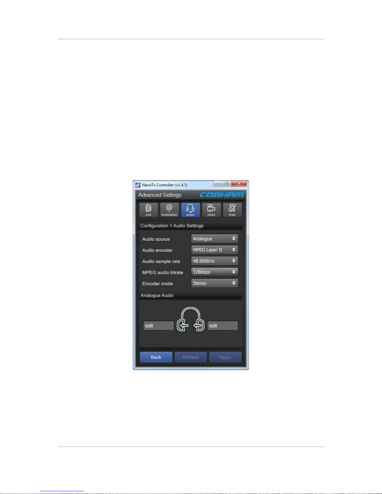
Solo7 Nano Transmitter
Commercial in
Confidence
Video, Transmitters, Solo7 Nano
Transmitter
100145
Revision: 8.0
Commercial in
Confidence
Page 7-58
7.10 Working with the Audio Tab
Before you Beg in
You’ll need:
To have connected your PC to the Nano Transmitter using Serial.
To have established a serial connection. (Green Connect button showing).
Step 1: Open the Advanced Window > Audio Tab
1. On the Main Window in the Switch Panel, click the Advanced button.
2. Click the Audio Tab.
Screenshot: Audio Tab
Figure 7-9 Audio Tab
Page 66
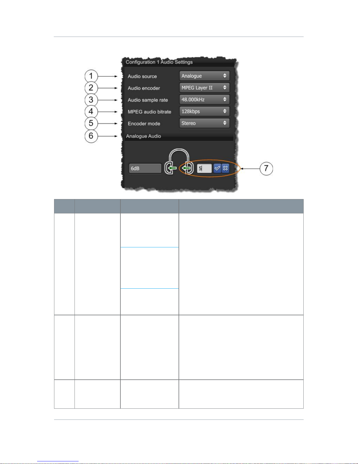
Solo7 Nano Transmitter
Commercial in
Confidence
Video, Transmitters, Solo7 Nano
Transmitter
100145
Revision: 8.0
Commercial in
Confidence
Page 7-59
Step 2: Configure the Audio Settings
No
Name
Options
Notes
1
Audio Source
Off
Analogue
Differential
HD Nano TX
Only:
Embedded. (Digital
audio from either
SDI or HDMI.
You can switch audio off, leaving all the
bandwidth available for video and data.
Analogue – When selected the audio input
cable can be used for mono left, mono right
or stereo pair.
Differential – When selected the audio input
cable can be used as a differential pair for
long cable runs on high quality microphones
(mono only).
2
Audio Encoder
MPEG Layer I
MPEG Layer II
You can select one of two modes to suit
operational and bandwidth requirements.
As you select each of these audio modes
and apply them, take a look at the Video
bitrates parameter and watch it change.
The higher the audio quality used the less
the video bandwidth available.
3
Audio Sample
Rate
48.000kHz
32.000kHz
This is the MPEG audio encoding sample-
rate. Generally the higher the number the
better the audio quality.
Page 67
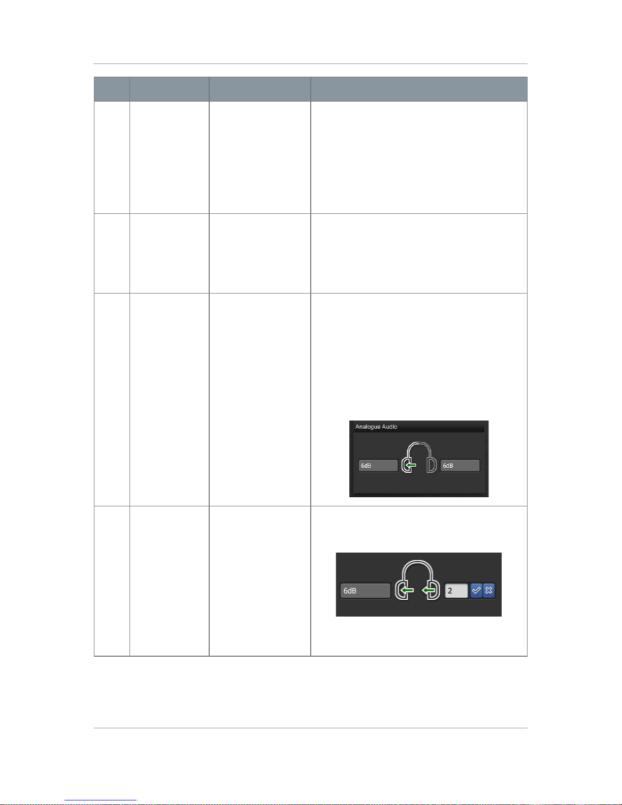
Solo7 Nano Transmitter
Commercial in
Confidence
Video, Transmitters, Solo7 Nano
Transmitter
100145
Revision: 8.0
Commercial in
Confidence
Page 7-60
No
Name
Options
Notes
4
MPEG Audio
Bit rate
Available rates
depend on current
audio encoder.
Layer I:
64 – 448kbps
Layer II:
32 – 384kbps
This is the MPEG audio encoding bit-rate.
Generally the higher the number the better
the quality.
5
Encoder Mode
Stereo
Left mono
Right mono
Dual mono
Select the audio mode you want to use.
Dual mono allows for different Gain values
on the left and right channel. Stereo uses
just one.
6
Analogue
Audio
Graphic
Note how the Analogue Audio graphic
changes to reflect the Encod er m o de you
have chosen. The arrows point to the
applicable gain value(s) in the selected
mode.
Stereo and Left mono uses left gain.
Right mono uses right gain.
Dual mono uses both gains.
7
Gain
0 to 66dB
You can apply different levels of gain to
each channel as required. Encoder mode
determines which gain value is used.
0=+4dBU
6=-2dBU are useful examples.
Table 7-12 – Audio Settings Key
Page 68
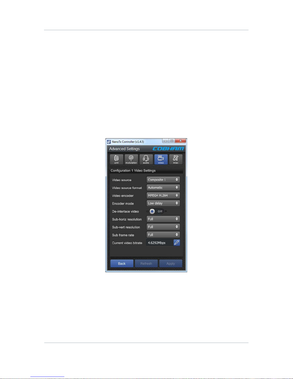
Solo7 Nano Transmitter
Commercial in
Confidence
Video, Transmitters, Solo7 Nano
Transmitter
100145
Revision: 8.0
Commercial in
Confidence
Page 7-61
7.11 Working with the Video Tab
Before you Beg in
You’ll need:
To have connected your PC to the Nano Transmitter using Serial.
To have established a serial connection. (Green Connect button showing).
Step 1: Open the Ad v an ced Window > Video Tab
1. On the Main Window in the Switch Panel, click the Advanced button.
2. Click the Video Tab.
Screenshot: V ideo Tab
Figure 7-10 Video Tab
Page 69
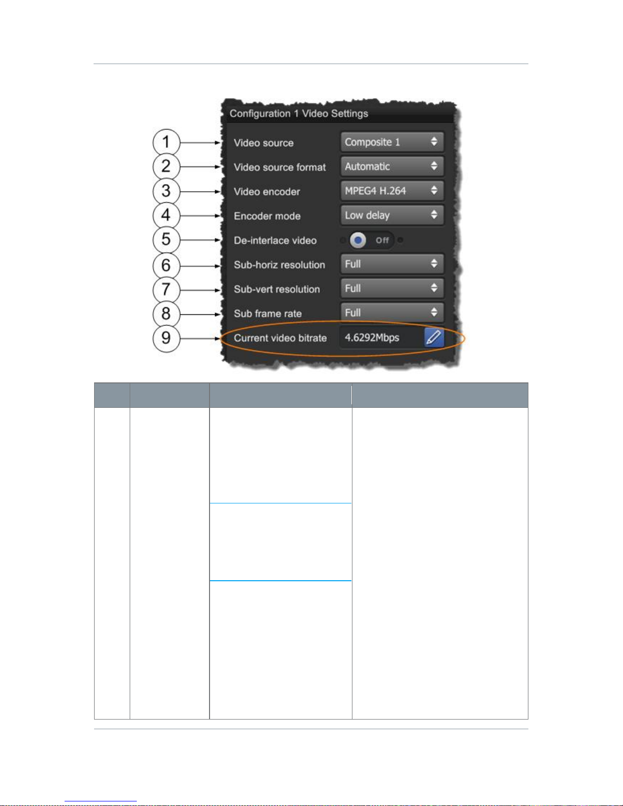
Solo7 Nano Transmitter
Commercial in
Confidence
Video, Transmitters, Solo7 Nano
Transmitter
100145
Revision: 8.0
Commercial in
Confidence
Page 7-62
Step 2: Configure the Video Settings
No
Name
Options
Notes
1
Video Source
Off
Composite 1
Composite 2
S-Video
HD Nano TX Only:
SDI (DIN 1.0/2.3
receptacle)
HDMI (Micro HDMI Type D
receptacle).
With the conventional Omnetics
Tri-Lobe Latching AV cable, there is
one yellow RCA Phono plug for
Video input. This is Composite 1.
The generic Omnetics 9-way
Breakout accessory cable can be
used to access two video inpu ts.
Here’s how you can use them:
For Composite Video, you can
use one or the other (but not both
at the same time).
Video 1: Composite 1 Input.
Video 2: Composite 2 Input.
For S-Video, you’ll use both like
this:
Video 1: S-Video Luma Input.
Video 2: S-Video Chroma Input.
You can switch video off, leaving
all the bandwidth available for
audio and data.
Page 70

Solo7 Nano Transmitter
Commercial in
Confidence
Video, Transmitters, Solo7 Nano
Transmitter
100145
Revision: 8.0
Commercial in
Confidence
Page 7-63
No
Name
Options
Notes
2
Video Source
Format
Automatic
PAL
NTSC
NTSC NP
HD Nano TX Only:
720p50, 720p59, 720p60,
1080i50, 1080i59, 1080i60,
1080p23, 1080p24,
1080p25, 1080p29,
1080p30, 1080psf23,
1080psf24, 1080psf25,
1080psf29, 1080psf30.
Select the Video format that
matches the camera you are using.
Alternatively the Automatic
setting enables the Nano TX to
determine if the signal is PAL or
NTSC automatically.
Power up standard in Automatic
mode defaults to PAL. This can be
changed by setting the input to
NTSC NP for example and then
back to Automatic.
3
Video Encoder
MPEG4 A SP
MPEG4 H.264
Select the Video Encoder mode to
suit your operation.
MPEG4 A SP may be required
backward compatibility with older
receivers.
MPEG4 H.264 generally provides
improved picture qualit y ove r ASP.
4
Encoder Mode
Standard Delay
Low Delay
Ultra Low Delay
Select the level of delay you can
accept.
Standard Delay mode provides
higher picture quality at the
expense of delay. Should be used
with long range modulation
parameters.
Ultra Low Delay mode provides
exceptionally low delay at the
expense of picture quality. Short
range modulation parameters will
generally be required.
Page 71

Solo7 Nano Transmitter
Commercial in
Confidence
Video, Transmitters, Solo7 Nano
Transmitter
100145
Revision: 8.0
Commercial in
Confidence
Page 7-64
No
Name
Options
Notes
5
De-interlace
Option Button
Blue=OFF
Orange=ON
When on, the de-interlace option
converts interlaced fi elds to a
progressive frame. This improves
picture quality on PC monitor type
devices. Having a progressive type
of image is also easier to encode
so you save bit rate too.
Use it when you want to display
video on a computer monitor and
save bit rate.
Don’t use it when you want to
preserve Vertical res o lution or
interlaced field rate.
6
Sub-horiz
resolution
Full, 3/4, 2/3, 1/2, 1/4
This is the fraction of the horizontal
resolution for whatever format you
have selected.
Let’s say you chose an HD 1080
format. This is actually 1920 x
1080 where 1920 is the horizontal
resolution.
If you choose Full then you’ll see
all 1920 pixels, if you choose 1/2
you’ll see a down-sampled picture
which requires much less bit-rate
to encoder.
7
Sub vert
resolution
Full, 1/2, 1/4
This is the fraction of the vertical
resolution for whatever format you
have selected.
Let’s say you chose an HD 1080
format. This is actually 1920 x
1080 where 1080 is the vertical
resolution.
If you choose Full then you’ll see
all 1080 lines, if you choose 1/2
you’ll see a down-sampled picture
which requires much less bit-rate
to encoder.
Note: Depending on the type of
video content, when using a subvertical resolution you may want to
enable the de-interlace option as
well.
Page 72

Solo7 Nano Transmitter
Commercial in
Confidence
Video, Transmitters, Solo7 Nano
Transmitter
100145
Revision: 8.0
Commercial in
Confidence
Page 7-65
No
Name
Options
Notes
8
Sub frame
rate
Full, 1/2, 1/4, 1/8, 1/24
If full frame rate is giving poor
quality, you can step this down
until you get an acceptable picture.
Note: Using a sub-frame rate will
force the Encoding mode to
Standard delay progressive.
9
Current Video
Bitrate
Pencil
Return Symbol
Normally left in automatic. Press
the Pencil Button and then the
Video bit rate box will become
active. Now you can manually set
the video bit rate you want to use.
Click the return symbol to return to
automatically calculated bitrate.
Table 7-13 – Video Settings Key
7.12 Working with the Misc Tab
Before you Beg in
You’ll need:
To have connected your PC to the Nano Transmitter using Serial.
To have established a serial connection. (Green Connect button showing).
Step 1: Open the Advanced Window > Misc Tab
1. On the Main Window in the Switch Panel, click the Advanced button.
2. Click the Misc Tab.
Page 73
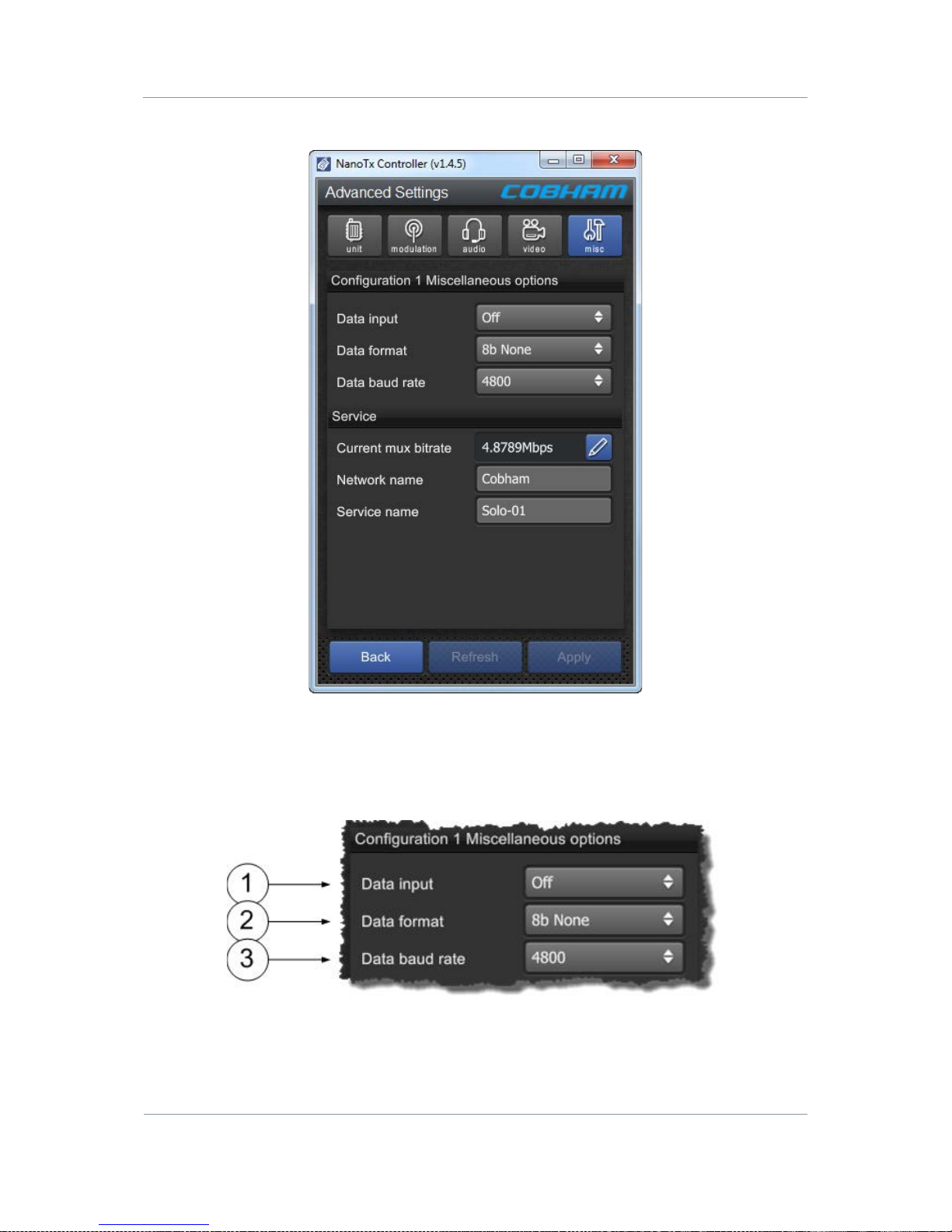
Solo7 Nano Transmitter
Commercial in
Confidence
Video, Transmitters, Solo7 Nano
Transmitter
100145
Revision: 8.0
Commercial in
Confidence
Page 7-66
Screenshot: Misc Tab
Figure 7-11 Misc Tab
Step 2: Configure the Miscellaneous Options
Page 74
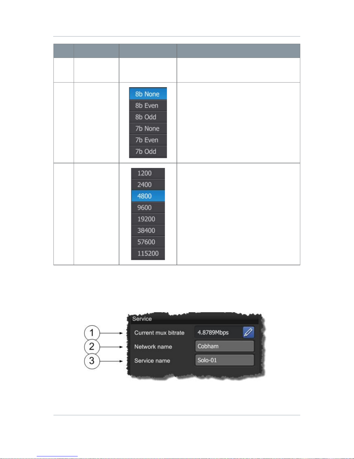
Solo7 Nano Transmitter
Commercial in
Confidence
Video, Transmitters, Solo7 Nano
Transmitter
100145
Revision: 8.0
Commercial in
Confidence
Page 7-67
No
Name
Options
Notes
1
Data Input
Off
On
Selects if RS232 data is passed over the
link.
2
Data Format
When you have switch data on, you can
select from one of the available modes.
8b (8-bit data) or 7b (7-bit data) must
match the data source, as must the parity.
3
Data Baud
Rate
This is the speed of serial data running
through the unit. This must match the data
source you are planning to use.
Table 7-14 – Miscellaneous Options Key
Step 3: Configure the Service Options
Page 75

Solo7 Nano Transmitter
Commercial in
Confidence
Video, Transmitters, Solo7 Nano
Transmitter
100145
Revision: 8.0
Commercial in
Confidence
Page 7-68
No
Name
Options
Notes
1
Current Mux
Bitrate
Any valid Bitrate.
When set to 0 the mux bit rate is defined
automatically based on modulation settings.
When set manually with RF output turned
off. This overrides the automatic
calculation. In this case it can be used to
adjust the stream rate on the ASI/chaining
outputs.
2
Network Name
Cobham is the
default or you can
use any valid
name.
The Network Name applies to the whole
transport stream (TS). Inside that TS there
may be many Services each with a Service
Name.
3
Service Name
Solo-01
The default is Solo-1. This is an identifier
for the service within the transport stream
(TS).
This must match the name at the receiver
for the service to be decoded.
Inside that TS there may be many Services
each with a Service Name.
Table 7-15 – Service Options Key
Page 76

Solo7 Nano Transmitter
Commercial in
Confidence
Video, Transmitters, Solo7 Nano
Transmitter
100145
Revision: 8.0
Commercial in
Confidence
Page 8-69
8. Appendix A – Cautions and Warnings
8.1 Cautions and Warnings
Serial
Area
Note
1
Enclosures
Do not remove any factory installed screws or fastenings.
Damage to the units may result and void any warranties.
Only authorised, trained personnel should open the product.
There are no functions that required the user to gain access to
the interior of the product. There are no user serviceable parts
inside.
2
Maintenance
Other than cleaning, no scheduled maintenance is required to
ensure proper function of the unit.
3
Environment
The equipment should not be used in hazardous or corrosive
atmospheres. Users ar e reminded of the necessity of complying
with restrictions regarding the use of radio devices in fuel
depots, chemical plants and locations where explosives are
stored and/or used.
4
Power Supply
Ensure that the power supply arrangements are adequate t o
meet the stated requirements of each product. Observe all
electrical safety preca utions.
5
Electro Static
Discharge
(ESD)
Precautions
ESD guidelines must be followe d for this electrostatic sensitive
device.
6
Lightning
Strike
There is a risk of lightning strike to antennas. The equipment
should not be assembled in an area at the time of lightning
activity. Antennas should be adequately protected from
lightning strikes.
7
Working at
Height
Observe caution when locating the device at height, for
example on a mast. Ensure the unit is well secured to prevent it
falling and injuring personnel.
8
Risk of Eye
Injury
Care should be taken to avoid eye contact with the antennas.
9
Cables
Connecting cables should not be positioned where they a r e
likely to become damaged or where they may present a trip
hazard.
Page 77
Solo7 Nano Transmitter
Commercial in
Confidence
Video, Transmitters, Solo7 Nano
Transmitter
100145
Revision: 8.0
Commercial in
Confidence
Page 8-70
Serial
Area
Note
10
Thermal
Control System
Any powered device will always produce heat as a by product of
its operation. If you operat e this device in an enclosed space
you must ensure it has adequate airflow to keep it cool.
Also, if worn close to the body, care must be taken to protect
the operator from excessiv e temperatures.
11
RF Emission
System
When using this device please ensure a distance o f 20 cm is
maintained between your device and your body while the
device is transmitting.
12
Aircraft Safety
Use of this equipment on board aircraft is strictly forbidden. Use
of radio transmitter equipment in an aircraft can endanger
navigation and other systems.
13
RF Emissions
WARNING: When wearing the Nano T r ansmitt er on the body,
you must only put the side with the label and the mounting
lugs towards your body.
14
RF Emissions
WARNING: The transmitter must be mounted at a minimum
of 5mm away from your body at all times.
15
RF Emissions
WARNING: The antenna must be kept vertical when the
transmitter is mounted near to the body.
16
RF Emissions
The device is operating on a Part 90 frequency.
17
RF Emissions
WARNING: T he equip ment is for occupational users only and
not for general public use.
8.2 EMC / Safety and Radio Approvals
The equipment has been designed to meet and has been tested against the following
harmonized EMC and safety standards:
8.3 CE Marking
The CE mark is affixed to all SOLO5 Transmitter products, and the CE Declaration of
Conformity, as well as the technical file is available on request.
Page 78

Solo7 Nano Transmitter
Commercial in
Confidence
Video, Transmitters, Solo7 Nano
Transmitter
100145
Revision: 8.0
Commercial in
Confidence
Page 9-71
9. Appendix B - Care and Maintenance
9.1 Caring for your Equipment
Do not subject the radio to physica l a buse, excessive shock or vibration
Do not drop, jar or throw the radio
Do not carry the radio by the antenna
Avoid exposure to excessive moisture or liquids
Do not submerse the radio unless it is designed to be submersible
Do not expose the radio to corr osives, solvents, cleaners or mineral spirit s
Avoid exposure to excessive cold and heat
Avoid prolonged exposure to direct sunlight
Do not place or leave radios on surfaces that are unstable
Always turn the radio off before installing optional accessories
Only use accessories int ended for the specific make and model of your radio, espe ci a l l y
batteries, chargers and power adapters
9.2 Charging
Use approved batteries, chargers and adapters designed specifically for your make and
model radio
Do not attempt to charge a wet radio or battery pack
Do not charge the radio or battery pack near anything flammable
Stabilize the battery p ack t o room temperature (72 degrees F) before charging
Do not charge radios and/or battery packs on wet or unstable surfaces
Do not leave radios and/or batteries in chargers for excessive periods
9.3 Working with Lithium Batteries
Charge only with the approved charging cable
Batteries are to be used only for the specified purpose. Incorrect use will invalidate the
warranty and may make the battery become dangerous.
Charge in a clean, dry environment, ideall y at 1 0 degrees Ce l sius. (0 to 45 degrees
Celsius is permissible).
Do not store or operate in direct sunlight for extended periods. Battery can be damaged
by over-heating, for example if placed on the rear parcel shelf of a motor vehicle.
Store in a cool dry environment. Storage at elevated temperatures can cause permanent
loss of capacity.
For short term (less than six months) storage, store in a fully charged state.
Page 79

Solo7 Nano Transmitter
Commercial in
Confidence
Video, Transmitters, Solo7 Nano
Transmitter
100145
Revision: 8.0
Commercial in
Confidence
Page 9-72
For extended periods of storage (more than one year) charge before storage and
recharge every six to nine mont h s .
Always fully recharge the battery after any storage period greater than one month before
use.
Do not store the battery with the charge depleted as this can cause failure of the battery
and invalidate warranty.
Do not short circuit
Do not immerse in water
Do not incinerate. Cells are likely to explode if placed in a fire
Dispose of batteries in accordance with the regulations in place for the Country of use.
Batteries are normally considered ‘separate waste’ and should not b e al lowed t o enter
the normal waste stream. Either return to the seller, or deliver to an approved re-cycling
facility.
9.4 Cleaning
Turn off the radio and remove batteries (if applicable) before maintenance
Use a clean, soft, damp cloth to clean the radio. A microfiber cl o th is recommended
Do not use alcohol or cleaning solutions to clean the radio
Do not immerse the radio in water to clean it
If the radio becomes wet, immediately dry it with a microfiber or other lint-free cloth.
9.5 Storage
Turn off the radio and remove batteries before storage
Store radios and battery packs in a cool, dry area at room temperature (72 degrees F).
Do not store radios and/or batteries in active chargers
9.6 Repairs
Do not attempt any repair. The radio contains no user serviceable parts . Contact the
Cobham Customer Service Centre or take it to a qualified repair technician.
9.7 Getting Technical Support
Step 1 – Contact Client Services
Technical support enquiries should be sent to the Client Services team.
Post: The Cobham Centre-Solent, Fusion 2, 1100 Parkway, Solent Business Park, Whiteley,
Hampshire, PO15 7AB, England.
Page 80

Solo7 Nano Transmitter
Commercial in
Confidence
Video, Transmitters, Solo7 Nano
Transmitter
100145
Revision: 8.0
Commercial in
Confidence
Page 9-73
Phone: +44 1489 566 750 then press 1 for support. Office hours: 0900-1700 UK time
excluding holidays.
Email: [email protected]
(no restricted content).
For technical support we undertake to get a first response to you in less than one working
day and a progress update at least every two weeks.
9.8 Using the Cobham RMA Service
You have a problem and all troubleshooting steps have been unsuccessful. You need to
contact Cobham for Return Material Authorisation (RMA) Service.
Step 1 – Email Cobham
To return something to Solent please Email [email protected]. We will then
send you an RMA request form to complete and return. We’ll then send you an RMA number
and shipping instructions.
Step 2 – Save your Personal Kit
Remove all personal kit or media from the device.
Step 3 – Pack the Unit
Use the original shipping container and packing materials if possible.
If the original packing materials are not available, wrap the equipment with soft material
(e.g. PU/PE form) then put the wrapped equipment into a hard cardboard shipping box.
Step 4 – Prepare an Information Sheet
Include a sheet with the following information.
Note: Please keep a copy of this sheet fo r your records.
Name
Address
Unit Serial Number
Date of Purchase or the original invoice number
Date of failure
A detailed description of the problems you have encountered
A list of the hardware / software configuration if applicable
Step 5 - Put the RMA Number on the Box
Clearly mark the outside of the shipping box with the RMA number. If an RMA number is not
present on the shipping box, receiving will be unable to identify it and it might be returned.
Step 6 – Send the Box to Cobham
Send the box using your normal shipping process.
Page 81
Solo7 Nano Transmitter
Commercial in
Confidence
Video, Transmitters, Solo7 Nano
Transmitter
100145
Revision: 8.0
Commercial in
Confidence
Page 10-74
10. Appendix C-Glossary
10.1 Glossary
0-9
Means…
16QAM
16-state Quadrature Amplitude Modulation.
64QAM
64-state Quadrature Amplitude Modulation.
A
Means…
AC
Alternating Current. Current that is continually changing in
magnitude and periodically in direction from a zero reference
level.
A/V
Audio/Video.
AES
In cryptography, the Advanced Encryption Standard (AES) is
an encryption standard adopted by the U.S. government. The
standard comprises three block ciphers, AES-128, AES-192 and
AES-256, adopted from a larger collection originally published as
Rijndael. Each AES cipher has a 128-bit block size, with key sizes
of 128, 192 and 256 bits, respectively.
ASI
Asynchronous Serial Interface. A streaming data interface
which often carries an MPEG Transport Stream.
An ASI signal can carry one or multiple SD, HD or audio programs
that are already compressed, not like an uncompressed SD-SDI
(270Mbs) or HD-SDI (1.45Gbs). An ASI signal can carry varying
amounts of data but is always padded to run at a fixed line rate of
270 Mb/s.
Amplification
The process of increasing th e s trength (current, voltage or power)
of a signal.
Amplitude
The level of an audio or other signal in voltage or current. The
magnitude of variation in a changing quantity from its zero value.
Amplitude Modulation
Modulation in which the amplitude of the carrier wave is varied
above and below its normal value in accordance with the
intelligence of the signal being transmitted. Also called AM.
Page 82
Solo7 Nano Transmitter
Commercial in
Confidence
Video, Transmitters, Solo7 Nano
Transmitter
100145
Revision: 8.0
Commercial in
Confidence
Page 10-75
A
Means…
Analogue
Analog transmission is a transmission method of conveying
voice, data, image, signal or video information using a continuous
signal which varies in amplitude, phase, or some other property in
proportion to that of a variable.
Antenna
An antenna (or aerial) is a transducer designed to radiate or
receive electromagneti c energy (generally RF).
Antenna Bandwidth
The frequency range over which a given antenna will accept
signals.
Antenna Gain
The effectiveness of a directional antenna as compared to a
standard non-directional antenna. It is usually expressed as the
ratio in decibels of standard antenna input power to directional
antenna input power that will produce the same field strength in
the desired direction. For a receiving antenna, the ratio of signal
power values produced at the r eceiver input terminals is used. The
more directional an antenna is, the higher is its gain.
Attenuation
Power loss resulting fr om conductor resistance and dielectric loss
within the insulating material used to separate the conductors.
B
Means…
BNC
Bayonet Neill-Concelman – A very common type of RF
connector used for terminating coaxial cable.
Bandwidth
The width of a band of frequencies used for a particular purpose.
C
Means…
COFDM
Coded Orthogonal Frequency Division Multiplexing is a
frequency-division multiplexing (FDM) scheme utilized as a digital
multi-carrier modulation method. A large number of closely-spaced
orthogonal sub-carriers are used to carry data.
D
Means…
D/C
Downconverter. A devi ce which converts microwave frequencies to
UHF frequencies for use in Co bham receivers.
Digital
A digital signal is a discontinuous signal that changes from one
state to another in discret e s teps.
Decibel
The standard unit used to express transmission gain or loss and
relative power levels. Also written as dB.
Page 83

Solo7 Nano Transmitter
Commercial in
Confidence
Video, Transmitters, Solo7 Nano
Transmitter
100145
Revision: 8.0
Commercial in
Confidence
Page 10-76
D
Means…
Decoder
Processor in a video receiver that converts digital video data to
analogue signals for replay on analogue monitors; or in certain
cases a software decoder, a program that decodes digital data for
replay on the PC (decompressi o n etc).
Demodulate
To recover the information originally impressed on the radio wave.
E
Means…
Electromagnetic fiel d
The field of force that an electrical current produces around the
conductor through which it flows.
Electromagnetic
Waves
A wave propagating as a periodic disturbance of the electri c and
magnetic fields and having frequency in the electromagnetic
spectrum; the means by which energy is transmitted from one
place to another.
Elementary Stream
(ES)
Elementary streams: These streams contain only one MPEG-2
video channel and no audio. Elementary streams are required if
you intend to use Milestone or any player that cannot operate
with Transport streams.
You must be in RTSP mode to use Elementary streams.
Encoder
A processor in a video transmitter which converts analogue video
from a camera to digital data.
F
Means…
FEC
Forward Error Correction is a system of error control for data
transmission, whereby the sender adds redundant data to its
messages, also known as an error-correction code. This allows
the receiver to detect and correct errors (within some bound)
without the need to ask the sender for additional data. The
advantage of forward error correction is that a back-channel is not
required, or that retransmission of data can often be avoided, at
the cost of higher bandwidth requirements on average. FEC is
therefore applied in situations where retransmissions are relatively
costly or impossible.
Firmware
Software which is installed directly on a device and i s intended
specifically for that device and is used to control it.
FOV
Field of View - The field of view (also field of vision) is the
angular extent of the observable worl d that is seen at any given
moment.
Page 84
Solo7 Nano Transmitter
Commercial in
Confidence
Video, Transmitters, Solo7 Nano
Transmitter
100145
Revision: 8.0
Commercial in
Confidence
Page 10-77
F
Means…
Fading
A periodic decrease in received signal strength
Frequency
The rate at which a process repeats itself. In radio
communications, frequency is exp ressed in cycles per second.
Signals also have a property called wavelength, which is inversely
proportional to the frequency.
Frequency
Modulation
The process of varying the frequency of a carrier wave, usually
with an audio frequency, in order to convey i ntelligence. Also
called FM.
FPGA
Field-Programmable Gate Arra y - an integrated circuit
designed to be configured by th e customer or designer after
manufacturing, hence "
field-programmable".
G
Means…
GUI
Graphical User Interface.
GHz
Gigahertz - One gigahertz is equal to 1,000 megahertz (MHz) or
1,000,000,000 Hz.
Gain
The increase in signal strength that is produced by an amplifier.
H
Means…
Hertz
One cycle per second.
I
Means…
IP Address
Internet Protocol Address – A unique numeric ID for a device
within a network.
IR
Infra Red - Infrared (IR) radiation is electromagnetic radiation
whose wavelength is longer than that of visible light.
Impedance
The total opposition offered by a circuit or component to the flow
of alternating current.
Page 85

Solo7 Nano Transmitter
Commercial in
Confidence
Video, Transmitters, Solo7 Nano
Transmitter
100145
Revision: 8.0
Commercial in
Confidence
Page 10-78
L
Means…
LOS and NLOS
Line-of-sight propagation refers to electro-magnetic radiat i o n
including light emissions travelling in a straight line. The rays or
waves are diffracted, refracted, reflected, or absorbed by
atmosphere and obstructions with material and generally cannot
travel over the
horizon or behind obstacles.
NLOS is Non Line-of-sight.
Load
A device that consumes electr i c al power.
Lux
The lux (symbol: lx) is the SI unit of i l luminance and luminous
emittance. It is used in photometry as a measure of the
apparent
intensity of light hitting or passing through a surface.
M
Means…
MHz
Megahertz is equal to 1,000,000 Hz
mW
Milliwatt - The milliwatt (symbol: mW) is equal to one
thousandth (10–3) of a watt.
MPEG
Moving Pictures Experts Group.
Modulation
To change the output of a transmitter in amplitude, phase or
frequency in accordance with the information to be transmitted.
Data is superimposed on a carrier current or wave by means of a
process called modulation. Signal modulation can be done in either
of two main ways: analogue and digital. In recent years, digital
modulation has been getting more common, while analogue
modulation methods have been used less and less. There are still
plenty of analogue signals around, however, and they will
probably never become tot ally extinct.
Multicast
Multicasting is sending data from a sender to multiple receivers
where each receiver signals that they
want
to receive the data.
N
Means…
nm
A nanometre (American spelling: nanometer; symbol nm) is a
unit of length in the metric system, equal to one billionth of a
metre (i.e., 10
-9
m or one millionth of a millimetre).
Page 86

Solo7 Nano Transmitter
Commercial in
Confidence
Video, Transmitters, Solo7 Nano
Transmitter
100145
Revision: 8.0
Commercial in
Confidence
Page 10-79
N
Means…
NMEA 0183
NMEA 0183 is a combined electrical and data specification for
communication between marine electronic devices such as echo
sounder, sonar, anemometer, gyrocompass, autopilot, GPS
receivers and many other types of instruments. It has been
defined by, and is controlled by, the U.S.-based National Marine
Electronics Associa tion.
NTSC
National Television Systems Committee.
Noise
Random pulses of electromagnetic energy generated by lightening
or electrical equipment .
O
Means…
Omni directional
antenna
An antenna whose radiation pattern shows equal radiation in all
horizontal directions.
Oscillation
A periodic, repetitive motion or set of values (voltage, current,
velocity).
P
Means…
PAL
Phase Alternate Line.
PIR
Passive Infra Red sensor (PIR sensor) is an electronic device
that measures infrared (IR) light radiating from objects in its field
of view.
PTZ
Pan, Tilt and Zoom – PTZ is a common way of referring to
controllable cameras.
Propagation
A phenomenon by which any wave moves from one point to
another; the travel of electromagnetic waves through space or
along a transmission line.
Q
Means…
QPSK
Quadrature Phase Shift Keying.
R
Means…
RF
Radio Frequency.
Page 87
Solo7 Nano Transmitter
Commercial in
Confidence
Video, Transmitters, Solo7 Nano
Transmitter
100145
Revision: 8.0
Commercial in
Confidence
Page 10-80
R
Means…
RTSP
Real Time Streaming Protocol (RTSP) is a network
control protocol designed for use in entertainment and
communications systems to control streaming media servers. The
protocol is used for establishing and controlling media sessions
between end points. Clients of media servers issue VCR-like
commands, such as play and pause, to facilitate real-time control
of playback of media files from the server.
Rx
Receiver, an electr onic device that changes a radio signal from a
transmitter into useful information.
Radiate
To transmit RF energy.
Radio Frequency
Any frequency of electrical energy capable of propagation into
space (usually above 20kHz). Also called RF.
S
Means…
SNR
Signal to Noise Ratio is an electrical engineering measurement
defined as the ratio of a signal power to the noise power
corrupting the signal.
Signal-to-noise ratio compares the level of a desired signal (such
as music) to the level of background noise. The higher the ratio,
the less obtrusive the background noise is.
Shannon Limit
The Shannon limit or Shannon capacity of a communications
channel is the theoretical maximum information transfer rate of
the channel, for a particular noise level.
Signal
In electronics, a signal is an electric current or el e ctromagnetic
field used to convey data from one place to another. The simplest
form of signal is a direct current (DC) that is switched on and off;
this is the principle by which the ear l y telegraph worked. More
complex signals consist of an alternating-current (AC) or
electromagnetic carrier that contains one or more data streams.
Streaming
Streaming is the transmission of digital audio or video or the
listening and viewing of such data without first storing it.
T
Means…
Tx
A transmitter is an electronic device which, usually with the aid
of an antenna, propagates an electromagnetic signal such as
radio, television, or other telecommunications.
Page 88
Solo7 Nano Transmitter
Commercial in
Confidence
Video, Transmitters, Solo7 Nano
Transmitter
100145
Revision: 8.0
Commercial in
Confidence
Page 10-81
T
Means…
TNC
The TNC (threaded Neill-Concelman) connector is a
threaded version of the BNC connector. The connector has a 50 Ω
impedance and operates best in the 0–11 GHz frequency
spectrum.
Transport Stream
(TS)
Transport streams: These streams can contain several MPEG-2
content channels and associated audio. All the channels are
multiplexed together, allowing the receiver t o choose which to
play back.
U
Means…
UDP
User Datagram Protocol (UDP) Sometimes called fire and
forget because there is no dialog between the sender and
receiver. If the receiver does not get a packet, the sender will
never know. However, UDP is very efficient when there is little
chance of errors (like in your LAN), or when TCP would provide
"too late" delivery.
USB
Universal Serial Bus
Unicast
Unicast is simply sending packets from one source to one
destination. For example, from one web server to one (or each)
person viewing a page on a web browser.
V
Means…
VHF
Very High Frequency – 30 MHz to 300 MHz
V
Volt.
Viterbi Decoder
A Viterbi decoder uses t he Viterbi algorithm for decoding a bit
stream that has been encoded using forward error correction
based on a Convolutional code.
W
Means…
Watt
The watt (symbol: W) is a derived unit of power in the
International System of Units (SI). It measures rate of energy
conversion. One watt is equivalent to 1 joule (J) of energy per
second.
Waveform
Signal shape.
Page 89

Solo7 Nano Transmitter
Commercial in
Confidence
Video, Transmitters, Solo7 Nano
Transmitter
100145
Revision: 8.0
Commercial in
Confidence
Page 10-82
W
Means…
Waveguide
A specially form hollow metal tube, usually rectangular in shape in
cross section, used to connect a High Power amplifier to the
antenna.
R1.3
Page 90

Solo7 Nano Transmitter
Commercial in
Confidence
Video, Transmitters, Solo7 Nano
Transmitter
100145
Revision: 8.0
Commercial in
Confidence
Page 11-83
11. Appendix D – Reference Material
11.1 Licensing your Unit
Before you Beg in
You’ll need:
To have connected your PC to the Nano Transmitter using Serial.
To have established a serial co n nection. (Green Connect button showing).
Step 1: Open the Upload Tab
1. On the Main Window in the Switch Panel, click the Upload button.
2. The Upload tab opens.
Step 2: License your Unit
1. On the Upload License Fi le pane, click the blue Folders button.
2. Navigate to where you have placed your license file.
3. You can use these buttons to explore any mapped drives you have on your PC.
4. In my example, the license files are located in my Downloads folder. They always end
in .lic. Click the license file you want to use and it will appear in the File name box.
Note: If you are unsure which licence is for your device, look at the filename. It will contain
an Electronic Serial Number (ESN). If it matches your unit’s ESN then this is your licence. In
this example, the middle part of the filename is -c9657cdb- which is the ESN for my Nano
Transmitter.
5. Click the Upload button.
6. You’ll see the Upload Status change to Upgrade Succeeded.
Page 91
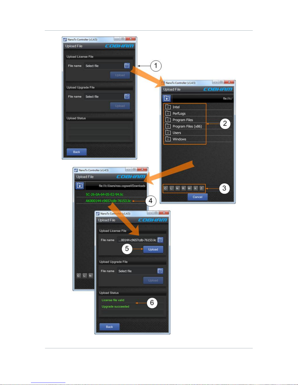
Solo7 Nano Transmitter
Commercial in
Confidence
Video, Transmitters, Solo7 Nano
Transmitter
100145
Revision: 8.0
Commercial in
Confidence
Page 11-84
Page 92
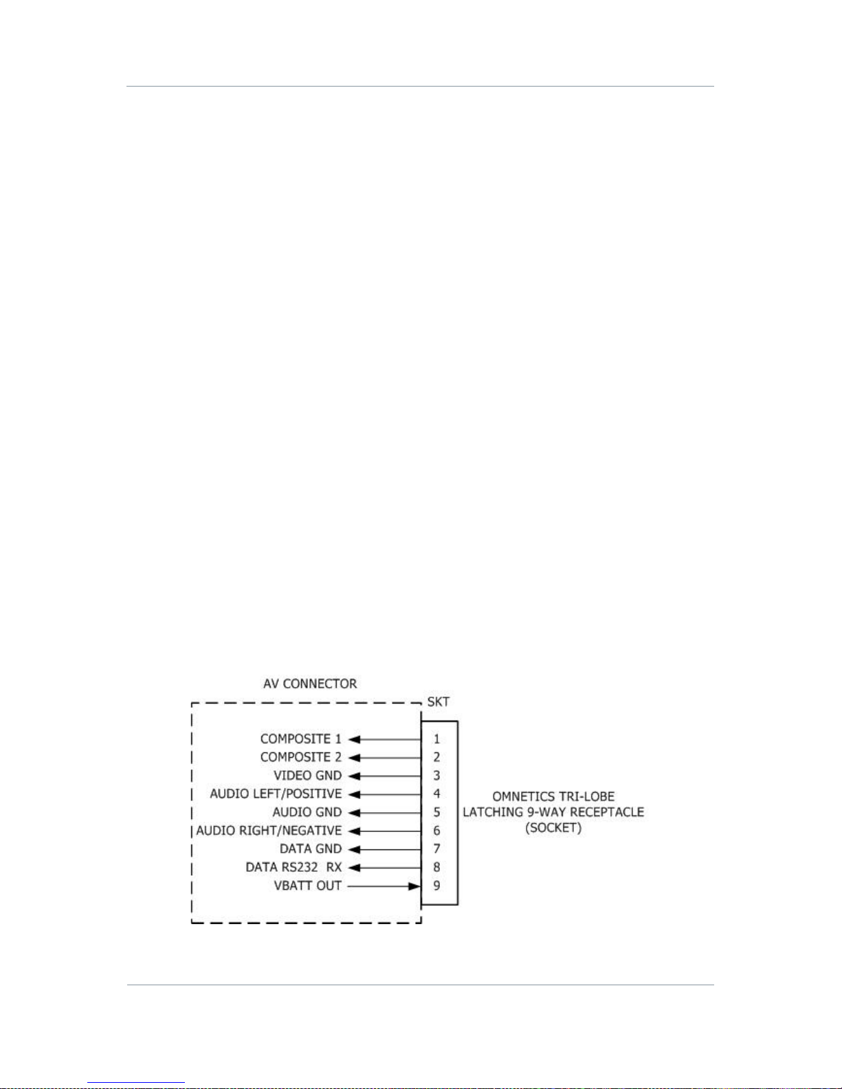
Solo7 Nano Transmitter
Commercial in
Confidence
Video, Transmitters, Solo7 Nano
Transmitter
100145
Revision: 8.0
Commercial in
Confidence
Page 11-85
11.2 Upgrading your Firmware
Before you Beg in
You’ll need:
To have connected your PC to the Nano Transmitter using Serial.
To have established a serial connection. (Green Connect button showing).
Step 1: Open the Upload Tab
1. On the Main Window in the Switch Panel, click the Upload button.
2. The Upload tab opens.
Step 2: Upgrade your Firmware
1. On the Upload Upgrade File pane, click the bl ue Folders button.
2. Navigate to where you have placed your upgrade file.
3. You can use these buttons to explore any mapped drives you have on your PC.
4. Click the upgrade file you want to use and it will appear in the File name box.
5. Click the Upload button.
6. You’ll see the Upload Status change to Upgrade Succeeded.
11.3 Pinouts
11.3.1 AV Connector – Omnetics Tri-Lobe Latching 9-way Receptacle
Page 93
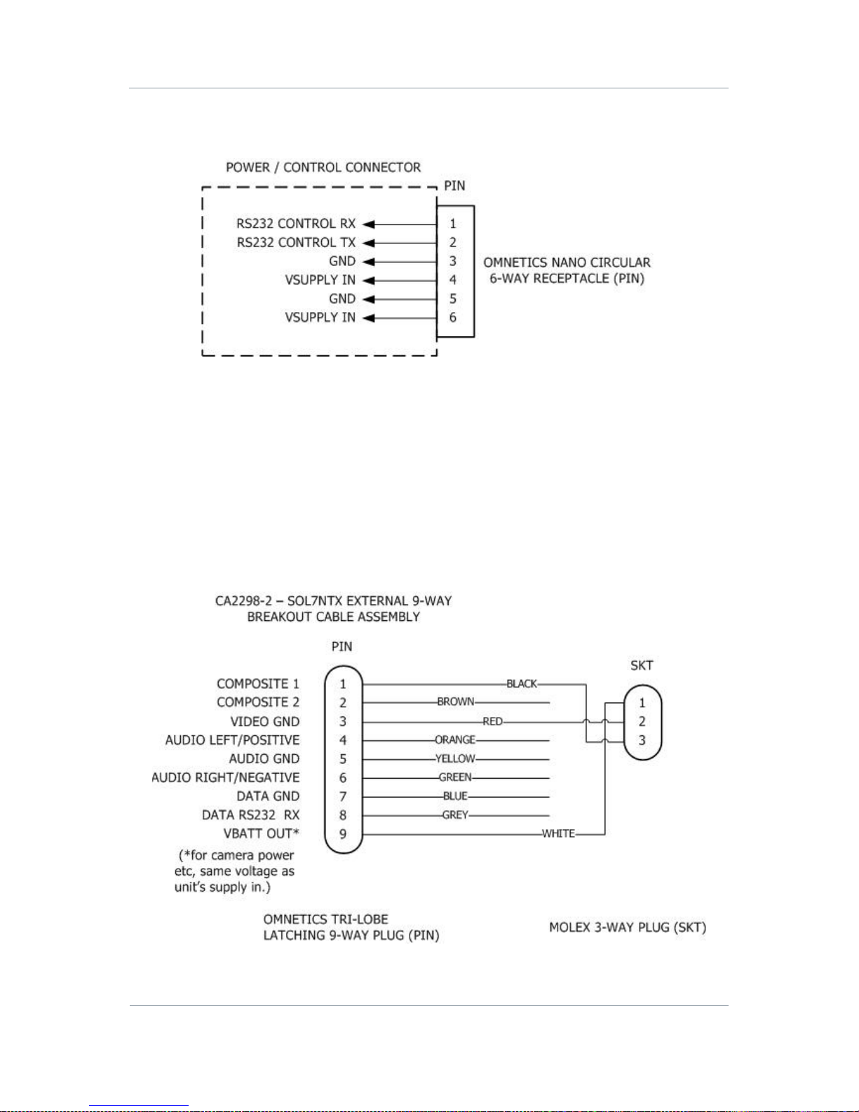
Solo7 Nano Transmitter
Commercial in
Confidence
Video, Transmitters, Solo7 Nano
Transmitter
100145
Revision: 8.0
Commercial in
Confidence
Page 11-86
11.3.2 Power / Control Connector – Omnetics Nano Circular 6-way
Receptacle
11.3.3 CA2298 SOL7NTX External 9-way Breakout Cable Assembly
This cable assembly has a 9-way plug at one end and a 3-way Molex plug at the other for
you to connect to the cameras supplied in the kit version of SOL7NTX Nano Transmitter.
There are five bare wires which you can use to make cables to suit your own application. Of
course you can remove the Molex plug to get at those cables too.
The diagram shows the signal / power on the Molex and bare wires.
Page 94

Solo7 Nano Transmitter
Commercial in
Confidence
Video, Transmitters, Solo7 Nano
Transmitter
100145
Revision: 8.0
Commercial in
Confidence
Page 11-87
11.4 Running the Nano TX Controller in Logging Mode
Before you Beg in
You’ll need:
To have connected your PC to the Nano Transmitter using Serial.
To have established a serial connection. (Green Connect button showing).
Step 1: Set up Logg ing Mode
1. Create a shortcut to the Nano TX Controller on your desktop and right-click it.
2. The Shortcut Properties window opens.
3. In the Target box add /l “log.txt” to the end of the line.
4. Click the Apply button.
5. Click the OK button.
6. Double-click your Nano TX Controller shortcut on your de sktop.
7. The Nano TX Controller application opens.
8. The logging symbol is now white indicating logging is running.
Note: In the target box you must leave the quote marks on the original target line, leave a
space then forward slash, lowercase L, quote mark, log.txt, close quote.
Page 95
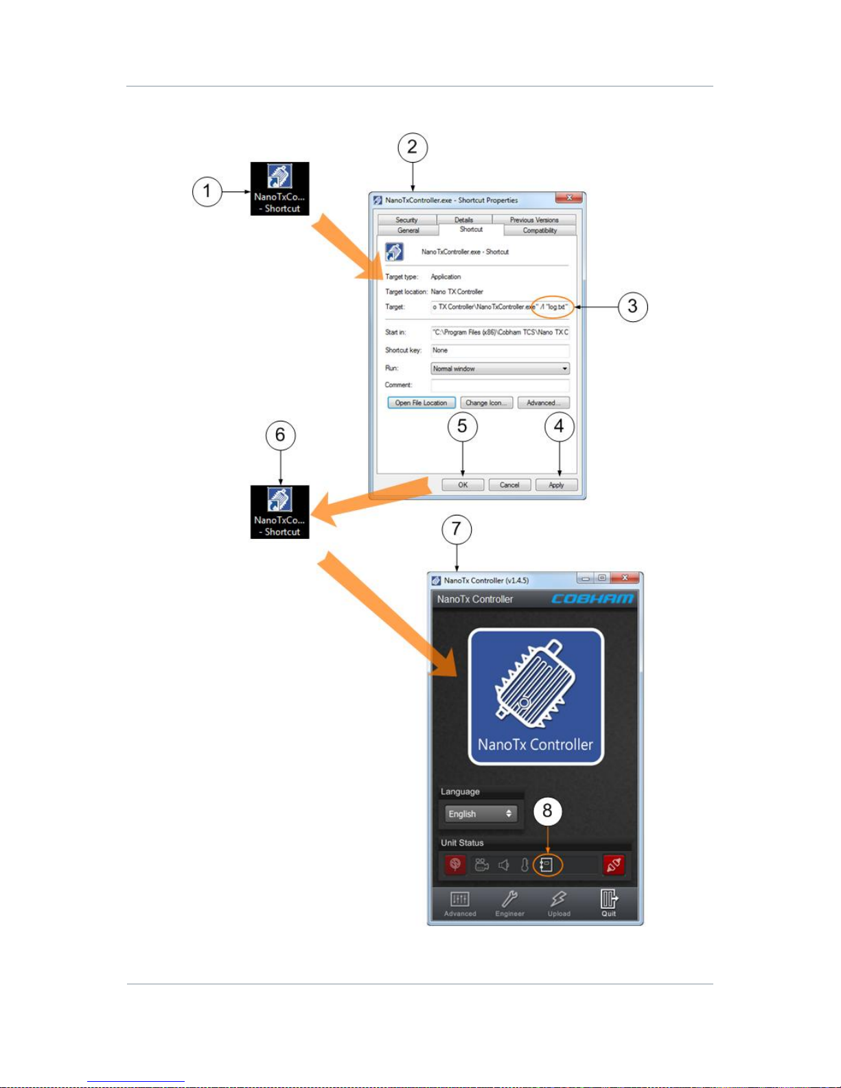
Solo7 Nano Transmitter
Commercial in
Confidence
Video, Transmitters, Solo7 Nano
Transmitter
100145
Revision: 8.0
Commercial in
Confidence
Page 11-88
Screenshot: Set up Logging Mode
Page 96

Solo7 Nano Transmitter
Commercial in
Confidence
Video, Transmitters, Solo7 Nano
Transmitter
100145
Revision: 8.0
Commercial in
Confidence
Page 11-89
11.5 Recovering the Logg ing File
Before you Beg in
You’ll need:
To have connected your PC to the Nano Transmitter using Serial.
To have established a serial connection. (Green Connect button showing).
Step 1: Recover the Logging File
1. Right-click the Nano TX Controller shortcut on your desktop.
2. The Shortcut Properties window opens.
3. Click Open File Location button.
4. Windows Explorer opens where your Nano TX Controller application (and Log file) is
located.
5. Double-click the log.txt file.
6. The log.txt file opens and displays your logged events.
Note: You may have to close the Nano TX Controller application to force all log contents to
be written to disk.
Page 97
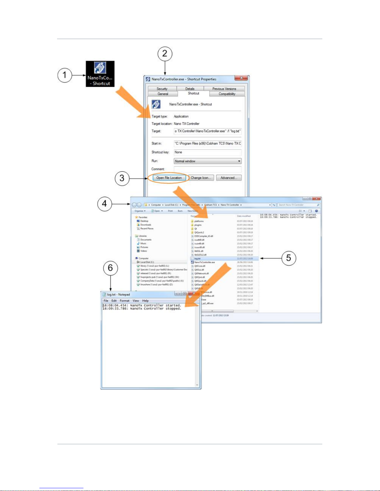
Solo7 Nano Transmitter
Commercial in
Confidence
Video, Transmitters, Solo7 Nano
Transmitter
100145
Revision: 8.0
Commercial in
Confidence
Page 11-90
 Loading...