

Page 1

Page 1 Specifications subject to change without notice
, 18th October 2004
SOLO2 and SOLO4
Users’ Manual
Users’ Manual
Version 2.8
7 October 2009
Cobham Surveillance
Domo Products
11 Manor Court, Barnes Wallis Road, Segensworth,
Hampshire, PO15 5TH, England
T: +44 (0)1489 566 750
F: +44 (0)1489 880 538
Page 2
2
1 Table of Contents
1 Table of Contents .................................................................................... 2
2 Change History........................................................................................4
3 About this Manual.................................................................................... 5
4 Introduction............................................................................................. 6
5 Warranty and Support..............................................................................7
5.1 Warranty Cover.........................................................................................7
6 Safety, Compliance and Approvals ...........................................................8
6.1 Safe Operating Procedures.........................................................................8
6.2 EMC / Safety and Radio Approvals ..............................................................8
6.3 CE marking ..............................................................................................8
7 Getting Started and Basic Operation.......................................................10
7.1 Which Model do I have? ........................................................................... 10
7.2 Getting Started with the Transmitter ...........................................................15
7.3 Getting Started with the SOLO Receiver ..................................................... 22
7.4 Powering on the System........................................................................... 31
7.5 Domo Batteries and Battery Charging.........................................................33
7.6 Using the Clip On 1W Amplifier ................................................................. 35
7.7 Using the booster 5W Amp ....................................................................... 37
8 Advanced Operation .............................................................................. 41
8.1 SOLO System PC Controller Application Software ....................................... 41
8.2 Transmitter Control Application..................................................................43
8.3 Receiver Control Application ..................................................................... 51
9 NETSTREAM IP Output Option ...............................................................59
9.1 General Info............................................................................................ 59
9.2 Streamer ................................................................................................59
9.3 Web Server ............................................................................................59
10 Software Decoder .................................................................................. 62
10.1 General Information .................................................................................62
10.2 Decoding Multicast Streams...................................................................... 63
10.3 Encrypted Streams .................................................................................. 65
10.4 Main Decoder Window ............................................................................. 67
10.5 Decoding Locally Stored Files ................................................................... 69
10.6 Miscellaneous application options .............................................................. 69
11 Fault Finding ......................................................................................... 71
11.1 Indicated Faults....................................................................................... 71
11.2 Fault Symptoms ...................................................................................... 72
12 LED Indicators....................................................................................... 73
13 Receiver On Screen Display ................................................................... 74
13.1 Input Status Page.................................................................................... 74
13.2 RF Advanced Page..................................................................................75
13.3 Engineering Data Page ............................................................................ 76
13.4 GPS Overlay........................................................................................... 76
13.5 Frequency Scan Page..............................................................................77
13.6 On Screen Display Control........................................................................ 80
14 Connector Pin Outs ...............................................................................84
Page 3

3
14.1 Power - 4-pin 0B LEMO Socket (TX and RX)...............................................84
14.2 Control Data and Expansion - 16-pin Hirose 3500 series connector & 0.1”
OEM header (TX Only).........................................................................................84
14.3 Control Data and Expansion - 16-pin Hirose 3500 series connector & 0.1”
OEM header (RX Only) ........................................................................................84
14.4 Combined A/V - 5-pin 0B LEMO socket (TX Only)........................................ 85
14.5 Audio - 5-pin 0B LEMO socket (Solo4RX) ................................................... 85
14.6 Audio - 3-pin 1B LEMO Socket (old style RX Only)....................................... 85
14.7 RS232 Control - 3-pin 0B LEMO Socket (old style RX Only) ..........................85
15 Control Protocols .................................................................................. 86
15.1 RS232 Control – General Principles ...........................................................86
15.2 Packet Structure Sending (from PC)........................................................... 86
15.3 Packet Structure Reply (from controlled device)...........................................87
15.4 Transmitter Command List........................................................................ 88
15.5 Receiver Command List ........................................................................... 94
16 Default Configurations ........................................................................... 98
Page 4

4
2 Change History
Version
Main Changes from Previous Version
Edited By
v1.0
Initial Release
MB
V1.1
Removed error stating that transmitter does not
support RS232 data
MB
V1.2
Warning added for static discharge on antennas
MB
V1.3
Additional information added:
Battery Charging
Clip on Amp
OSD analysis
Error in MPEG4 transmitter commands
corrected.
MB
DE
V1.4
Audio levels corrected
SOL4RX Added
MM
MB
V1.5
Updated chaining mode RS232 commands
MB
V1.6
Added new Solo4RX box Audio connector
details
NMcS
V1.7
Added new TX and RX controller sections for V2
controllers, added new TX system diagram,
updated Software Decoder
NMcS
V1.8
Updated receiver remote control commands list
MZ
V1.9
Added detail on Software decoder licensing
NMcS
V2.0
Added the User name and Password required to
Browse to the IP Streamer
NMcS
V2.1
Added MPEG audio and I Q trim commands
NMcS
V2.2
Added missing 1.25MHz entry in receiver
remote control commands list
MZ
V2.3
Added video frame lock mode in receiver
commands list. Removed 625-line format mode
(obsolete command)
MZ
V2.4
V2.3 converted to new Cobham template
AT
V2.5
Added new down-converter details
NMcS
V2.6
Added new OSD manual section and related
receiver remote commands
Fixed section numbering and TOC
RL
V2.7
Updated transmitter remote commands
RL
V2.8
Updated transmitter remote commands
TPM
Page 5

5
3 About this Manual
This manual describes the operation of domo SOLO2 and SOLO4
digital wireless systems. The manual is divided into three main
sections.
• Getting started and basic operation
This section describes to users how to deploy and use a domo SOLO
system.
• Advanced operation
This section describes the operation of the system in more detail,
concentrating particularly on how to store and recall configurations, wit
h
use of the PC Controller Application.
• Technical reference
This section provides technical specification and control protocol data
and will be of interest to those integrating the SOLO system into larger
systems.
Page 6

6
4 Introduction
The domo SOLO4 and SOLO2 product range enables the user to build
wireless digital microwave video systems. The domo SOLO4 and
SOLO2 products have been designed to provide rugged point-to-point
links for high quality full frame rate video, and audio, even in non line of
sight and urban environments.
Existing analogue systems suffer from impairments such as video noise,
loss of colour information and poo
r image quality when line of sight
cannot be maintained, and solutions based on wireless internet
standards and PC platforms deliver poor quality video.
The domo SOLO4 and SOLO2 system is a digital system that uses the
COFDM modulation technique, which effectively eliminates the
problems caused by multipath and reflections.
The SOLO product range allows law enforcement, surveillance and
emergency service
communities to now receive the highest quality
video images, in real time, direct from personnel, buildings and vehicles.
The domo SOLO2 system employs the DVB-T 2K carrier COFDM
technology.
The domo SOLO4 system employs a revolutionary narrow band
2.5MHz COFDM technology which demonstrates better propagation for
longer range links, and extra bandwidth efficiency. The domo SOLO4
system can also be upgr
aded to include a 1.25MHz COFDM modulation
and MPEG4 compression for excellent range performance.
The domo SOLO4 and SOLO2 systems employ common transmitter
and receiver hardware.
• The SOLO4 and SOLO2 transmitter is a lightweight, low-power
transmitter suitable for body-worn applications where size, weight and
power consumption are at a premium.
• For longer range applications such as vehicle transmissions, the
SOLO4 or SOLO2 transmitter can be upgraded with the use of a
booster amplifier.
• The SOLO4 and SOLO2 receivers are diversity input receivers with
extensive built in spectrum analysis tools. The receivers can be fitted
with an optional NETSTREAM card, which then gives the option of
streaming the received video onwards over IP networks.
IMPORTANT NOTE
The SOLO4 and SOLO2 product range has been specifically designed for government
security and law enforcement users, the equipment will tune across frequencies that are
only available to licensed government users. Non-government users should employ the
equipment restricted to the license exempt bands only typically 1.389 to 1.399GHz, 2.400
to 2.483GHz and 5.725 to 5.875GHz
Page 7

7
5 Warranty and Support
5.1 Warranty Cover
domo offers a 12 month standard product warranty. During this period,
should the customer encounter a fault with the equipment we
recommend the following course of action:
• Check the support section of the website for information on that product
and any software/firmware upgrades. If fault persists;
• Call our support line and report the fault. If fault persists and you are
informed to return the
product please obtain an RMA number from the
domo support department, and ship the equipment with the RMA
number displayed and a description of the fault. Please email the
support section the airway bill/consignment number for tracking
purposes.
• If you have extended warranty provisions then domo will send an
immediate advance replacement to you. Under most circumstances
this must be returned once the
fault item is repaired.
Depending on the nature of the fault domo endeavor to repair the
equipment and return it to the customer within 14 days of the item
arriving at our workshops.
Obviously it is impossible to cater for all types of faults and to manage
100% replacement part availability, and delays are sometimes
inevitable. This is why domo recommend that its customers take out an
extended warranty
(which includes advanced replacement of faulty
items), and/or hold a basic level of spare parts, which can be held by
domo on the customer’s behalf.
Please contact domo for details of packages that can be tailored to meet
your individual needs, whether they are service availability, technical
training, local geographic support or dedicated spares holdings.
Page 8

8
6 Safety, Compliance and Approvals
6.1 Safe Operating Procedures
• Ensure that the power supply arrangements are adequate to meet the
stated requirements of each SOLO4 or SOLO2 product.
• Operate within the environmental limits specified for the product.
• Do not subject the indoor equipment to splashing or dripping liquids.
• Only authorized, trained personnel should open the product. There are
no functions that required the User to gain access to the interior o
f the
product.
6.2 EMC / Safety and Radio Approvals
The equipment has been designed to meet and has been tested against
the following harmonized EMC and safety standards:
• EN 301 489-1 & EN 301 489-5
• EN 61000-3-2:2000
• EN 61000-3-3:1995
• EN 55022:1998, Class B
• EN 61000-4-2:1995
• EN 61000-4-3:1996
• EN 61000-4-4:1995
• EN 61000-4-5:1995
• EN 61000-4-6:1996
• EN 61000-4-11:1994
• EN 60950:2000
• The license exempt equipment (SOL2TX-138139, SOL2TX-240248,
SOL4TX-138139 and SOL4TX-240248) meets the following radio
approvals.
• EN 302 064-1
6.3 CE marking
The CE mark is affixed to all SOLO4 and SOLO2 products, and the CE
Declaration of Conformity, as well as the technical file are available on
request.
Page 9

9
Page 10
10
7 Getting Started and Basic Operation
7.1 Which Model do I have?
Each unit in the domo SOLO4 and SOLO2 product range is marked
with two panels.
• Product Code Panel. Give product code and manufacturers
information.
• CE and Serial Number Panel. Gives CE mark and product
serial number.
The domo product code can be referenced in the table below.
Product Code
Product
Accompanying items
SOL2TX-115140 (1.15 to 1.4GHz)
SOL2TX-228255 (2.28 to
2.55GHz)
SOL2TX-034047 (340 TO
470MHz)
SOL2TX-057067 (575 to 675MHz)
SOL2TX-310340 (3.1 to 3.4GHz)
SOL2TX-488515 (4.88 to 5.1GHz)
SOL2TX-560590 (5.6 to 5.9GHz)
SOL2TXLE-138139 (1.389 to
1.399GHz)
SOL2TXLE-240248 (2.4 to
2.483GHz)
100mW DVB-T
Digital Video
transmitter
Cables:
Video and audio 2m
Control 3m
DC Power 2m
SOL4TX-115140 (1.15 to 1.4GHz)
SOL4TX-228255 (2.28 to
2.55GHz)
SOL4TX-034047 (340 TO
470MHz)
SOL4TX-057067 (575 to 675MHz)
SOL4TX-310340 (3.1 to 3.4GHz)
SOL4TX-488515 (4.88 to 5.1GHz)
SOL4TX-560590 (5.6 to 5.9GHz)
100mW DVB-T
and Narrow
Band Digital
Video
transmitter
Cables:
Video and audio 2m
Control 3m
DC Power 2m
domo SOL4TX-228255
S-Band
Made in the UK
Page 11
11
SOL4TXLE-138139 (1.389 to
1.399GHz)
SOL4TXLE-240248 (2.4 to
2.483GHz)
SOL2RX
SOLO2
Receiver
Additional Units:
Cables:
2 lengths of 3m low loss RF
cable
AC/DC power supply
Video 3m
Audio 3m
Control 3m
SOL4RX
SOLO4
Receiver
Additional Units:
Cables:
2 lengths of 3m low loss RF
cable
AC/DC power supply
Video 3m
Audio 3m
Control 3m
SOLAMP1W
1W Clip on
Amp
AMP 1W Clip On Video TX
SOL2 or SOL4 1.25 to 2.5Ghz
Note: SOLO2 / 4 Receivers are available in two box styles, referred to as Box Style 1 and
Box Style 2, through the remainder of the document.
Note: Receivers are made frequency specific by the addition of the appropriate downconverters.
DC-100140
L-band to UHF
down-converter
For use with SOLRX receiver
DC-225265
S-band to UHF
down-converter
For use with SOLRX receiver
DCB-450500
C-band to UHF
down-converter
For use with SOLRX receiver
DCB-550600
5.7GHz to UHF
down-converter
For use with SOLRX receiver
Note: DC-XXXXXX units are old style square down-converters. DCB-XXXXXX
are new style Barrel down-converters. See section
Page 12

12
Controls
Transmitter Control Panels:
SOLO2 and SOLO4 transmitters are equipped with a standard LED
(Light Emitting Diode) and push button panel. The panel is as depicted
below, and the buttons and LEDs have meanings as explained in the
table.
LED / Button
Colour
Meaning / Use
Alarm LED
Red
When lit indicates alarm or fault condition on equipment. Usually
means no lock to incoming video.
Front Panel Lock
LED
Yellow
When lit indicates the stream is encrypted (v 3 software and above)
RF LED
Green
Transmitter: When lit indicates RF output is active.
LED 1 to 8
Green
Indicates which of the 8 stored configurations is currently selected.
Range Mode
LEDs
Green
SOLO2 Transmitter: These LEDs have no function
SOLO4 Transmitter: Indicates range mode
Ultra Long Range: 1.25MHz QPSK FEC1/3 (optional)
Long Range: 2.5MHz QPSK FEC1/3
Medium Range: 2.5MHz QPSK FEC2/3
Short Range: 2.5MHz 16QAM FEC2/3
RF Button
-
Transmitter:
Pressing the RF button toggles the units RF output between OFF
and ON.
Holding down button toggles unit into standby mode.
Config Button
-
The config button when pressed selects the next configuration from
memory.
Holding down button toggles front panel lock.
Mode Button
-
SOLO2 Transmitter – No function
SOLO4 Transmitter – Toggles between the range modes previously
described.
CONFIG
RF
1
2
3
4
5
6
7
8
RF
ALARM
MODE
Page 13
13
Receiver Control Panels:
SOLO4 and SOLO2 Receivers can be fitted with one of two LED (Light
Emitting Diode) and push button panel styles depending on model type
Receiver Panel Style 1, Fitted on Box Style 1.
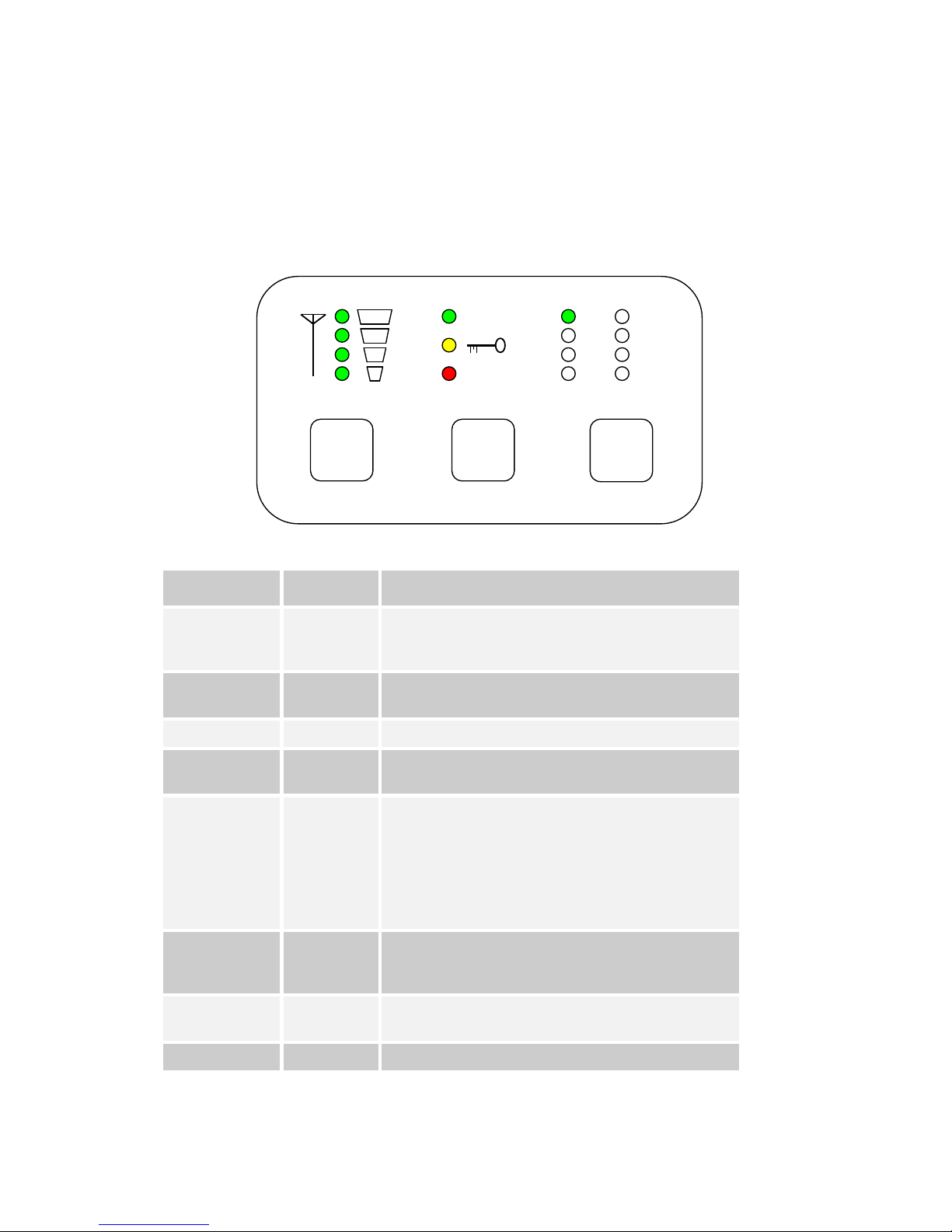
Receiver LED and Button Meaning on panel Style 1
LED / Button
Colour
Meaning / Use
Alarm LED
Red
When lit indicates alarm or fault condition on equipment. Usually
means no lock to incoming RF, or encrypted video that can not be
de-encrypted.
Front Panel Lock
LED
Yellow
When lit indicates the stream is encrypted.
RF LED
Green
Indicates RF lock when ON.
LED 1 to 8
Green
Indicates which of the eight stored configurations is currently
selected.
Range Mode
LEDs
Green
Indicates approximate signal strength level
1 LED On = low signal level
2 LED On = medium signal level
3 LED On = good signal level
4 LED On = very good signal level
RF Button
-
Pressing the RF button toggles the OSD (On Screen Display
Function) of the receiver, and cycles between pages (see section
13).
Config Button
-
The config button when pressed selects the next configuration from
memory.
Mode Button
-
No Function
CONFIG
RF
1
2
3
4
5
6
7
8
RF
ALARM
MODE
Page 14
14
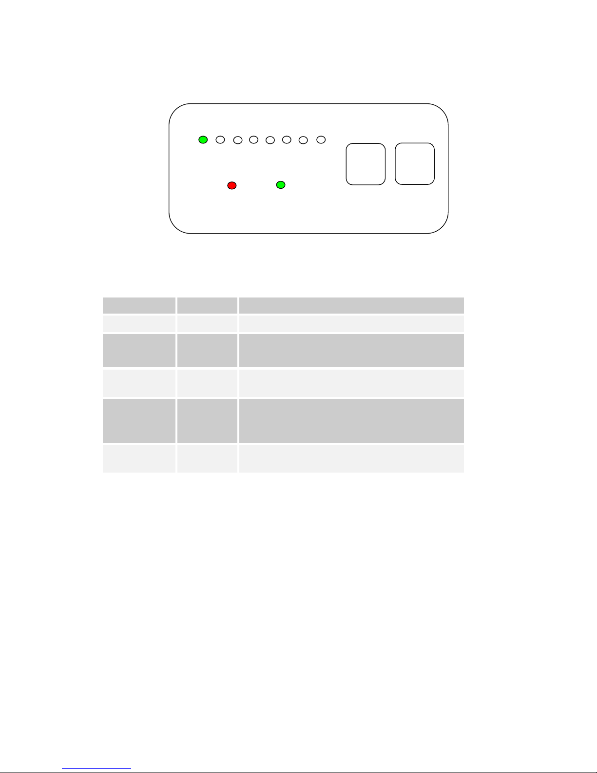
Receiver Panel Style 2, Fitted on Box Style 2.
Receiver LED and Button Meaning on panel Style 2
LED / Button
Colour
Meaning / Use
Alarm LED
Red
When lit indicates alarm or fault condition on equipment.
RF LED
Green
Receiver:
When lit indicates receiver has signal lock.
LED 1 to 8
Green
When lit permanently, indicates which of the eight stored
configurations is currently selected.
RF Button
-
Receiver:
Pressing the RF button enables/disables the on screen display
diagnostic function.
Config Button
-
The config button when pressed selects the next configuration from
memory.
1 2 3 4 5 6 7 8
RF
CONFIG
ALARM
RF
Page 15
15
7.2 Getting Started with the Transmitter
Cables and Connections
This section describes how to connect the following domo model
numbers.
• SOL2TX-115140 (1.15 to 1.4GHz)
• SOL2TX-228255 (2.28 to 2.55GHz)
• SOL2TX-034047 (340 TO 470MHz)
• SOL2TX-057067 (575 to 675MHz)
• SOL2TX-488515 (4.88 to 5.1GHz)
• SOL2TX-560590 (5.6 to 5.9GHz)
• SOL2TX-310340 (3.1 to 3.4GHz)
• SOL2TXLE-138139 (1.389 to 1.399GHz)
• SOL2TXLE-240248 (2.4 to 2.483GHz)
• SOL4TX-115140 (1.15 to 1.4GHz)
•
SOL4TX-228255 (2.28 to 2.55GHz)
• SOL4TX-034047 (340 TO 470MHz)
• SOL4TX-057067 (575 to 675MHz)
• SOL4TX-488515 (4.88 to 5.1GHz)
• SOL4TX-560590 (5.6 to 5.9GHz)
• SOL4TX-310340 (3.1 to 3.4GHz)
• SOL4TXLE-138139 (1.389 to 1.399GHz)
• SOL4TXLE-240248 (2.4 to 2.483GHz)
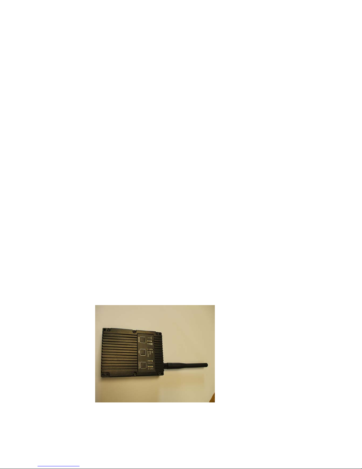
The picture below shows the domo SOLO2 and SOLO4 transmitter.
The domo transmitter is supplied with the following cables.
• Combined Video and Audio 2m
Page 16
16
• Control 3m
• DC Power 2m
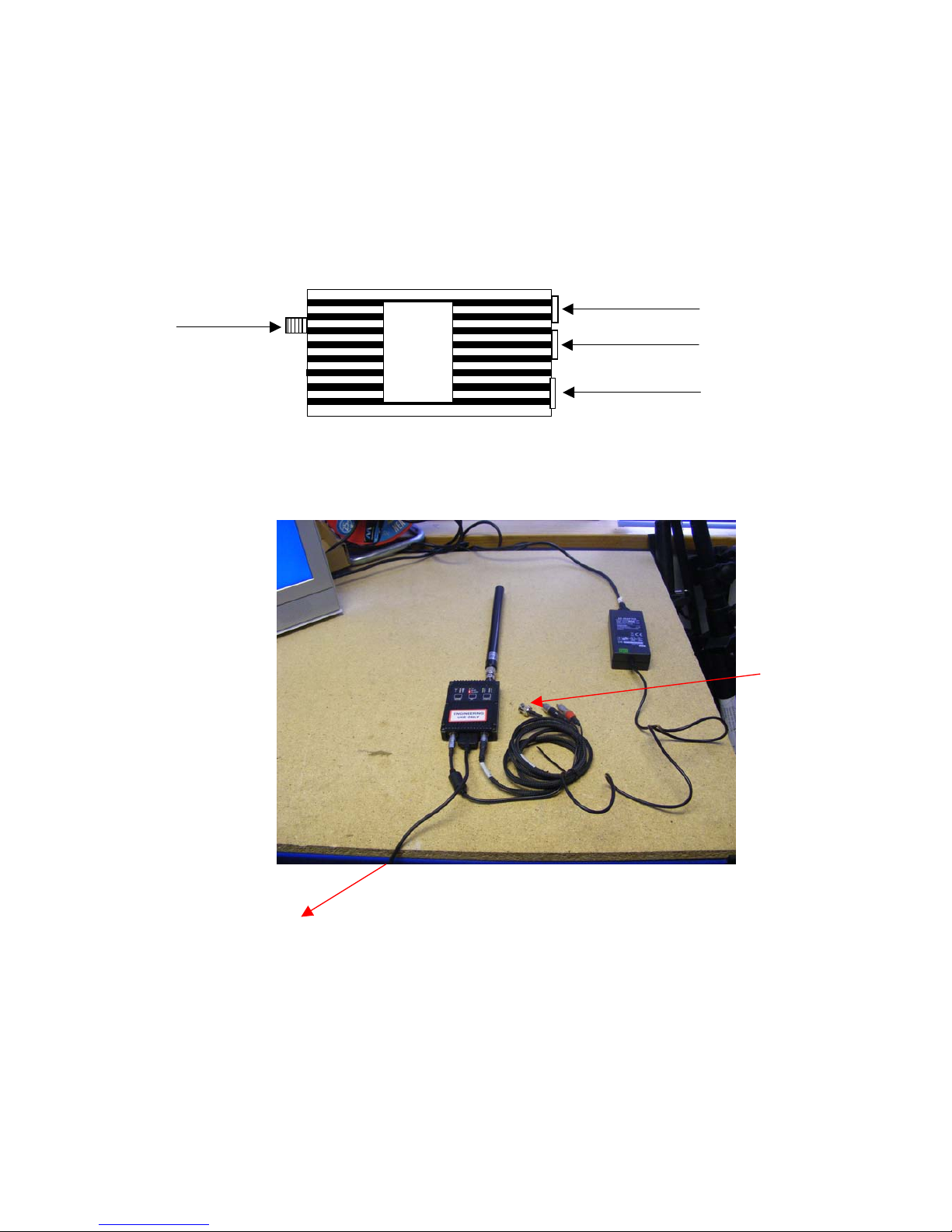
The domo transmitter should be connected as shown below.
As a typical example – including the control link from the PC,.
Audio Cable
Data and Control Cable
DC Power Cable
Antenna
To Computer
To Computer
To Camera
Page 17

17
Video and Audio
Push the LEMO connector into the socket labelled ‘AV’, taking care to
align the connectors. Connect the video and audio sources.
Connector
Signal
Video BNC
75 ohm composite video source, PAL or NTSC
software selectable
Audio Plugs
Line / Microphone level audio, switchable.
Line level -2dBu clip level low impedance
source (< 600 ohm)
Microphone level 12, 24, 36 and 48dB preamp
stages software switchable
Microphone power is provided on the audio connectors at approximately 3V (suitable for
Electret microphones)
Typically the video source will be a small colour or black and white CCD
camera.
Typically the audio source will be an Electret microphone.
DC Power
The transmitter unit can be powered from a nominal 12V DC supply or
an AC to DC adapted supply.
Push the LEMO connector on the DC power cable into the socket
labelled 12V, taking care to align the connectors. Connect the banana
connectors on the other end of the ca
ble to a suitable DC source.
The 12V DC input has the following characteristics.
• Input Voltage Range – 5.9V to 16V, reverse voltage protected.
• Current draw - 0.48 to 0.4A at 12V (mode dependant)
domo can supply optional AC to DC converter blocks to power the
transmitter unit, the domo part number is PSU12
Page 18
18
Antennas
domo transmitters are supplied as standard without antennas. An
antenna must be connected for normal operation. The transmitter unit is
supplied with a panel mounted SMA connector which carries the RF
output. The antenna should be connected by screwing it onto the SMA,
but care should be taken to not over tighten the connector.
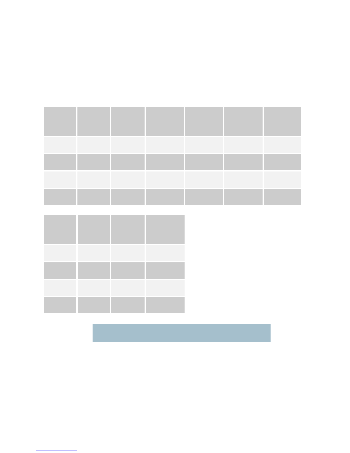
The transmitter has the following RF output characteristics.
RF Spec
Model
Number
ending 034047
Model
Number
ending 057067
Model
Number
ending 115140
Model
Number
ending 228255
Model
Number
ending 138139
Model
Number
ending 240248
Output
Frequency
340 to
470MHz
575 to
675MHz
1.15 to
1.40GHz
2.28 to
2.55GHz
1.389 to 1.399
GHz
2.400 to 2.483
GHz
Output
Bandwidth
2.5MHz
2.5MHz
2.5MHz
2.5MHz
2.5MHz
2.5MHz
Output
Power
100mW
(nominal)
100mW
(nominal)
100mW
(nominal)
100mW
(nominal)
100mW
(nominal)
10mW
(nominal)
Output
Impedance
50 ohm
50 ohm
50 ohm
50 ohm
50 ohm
50 ohm
RF Spec
Model
Number
ending 310340
Model
Number
ending 488515
Model
Number
ending 560590
Output
Frequency
3.1 to
3.4GHz
4.88 to
5.15GHz
5.6 to 5.9GHz
Output
Bandwidth
2.5MHz
2.5MHz
2.5MHz
Output
Power
100mW
(nominal)
100mW
(nominal)
100mW
(nominal)
Output
Impedance
50 ohm
50 ohm
50 ohm
Note. It is recommended that the antennas be connected directly to the transmitter unit.
The use of RF cables at this point will degrade the performance of the system.
The optimum choice of antenna will vary according to application. The
following table gives some suggestions for suitable transmit antennas
with the associated domo part number.
Page 19
19
Application
Antenna model number
Mobile body worn application
1.00 to 1.40GHz - ANTBCL
2.28 to 2.50GHz - ANTBCS
Mobile vehicle application
1.00 to 1.40GHz – ANT4L
2.28 to 2.50GHz - ANT4S
4.80 to 5.15GHz – ANT6C
Long range point to point link
1.00 to 1.40GHz – ANT12L
2.28 to 2.50GHz – ANT12S
Note. When using antenna types ANT4L, ANT4S, ANT6C, ANT12L and ANT12S
with domo transmitters SMA to TNC adaptor connectors will be needed.
Other antennas for more specialist applications, such as aircraft use or
covert surveillance use are available on request from domo.
Control Cable
The control cable is used for connecting the transmitter unit to a PC
when using the domo PC control application. The PC control
application is described in more detail the Advanced Operation section
of this handbook.
Installation Notes
The domo transmitter has been designed specifically for body worn
applications; however it is a general-purpose wireless video transmitter
and can be used in many applications including the following.
• Body worn portable applications
• Vehicle based applications
This section gives guidelines for how to install the transmitter in the
above applications.
Page 20
20
Body Worn Applications
Body worn applications will either be covert or overt and this will dictate
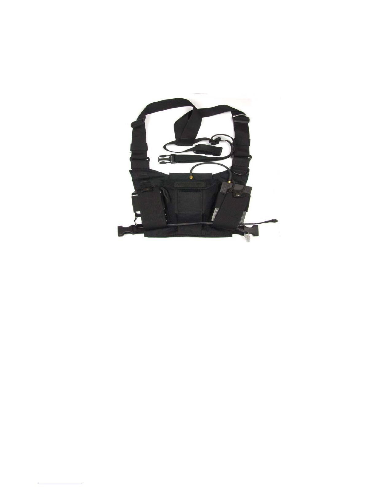
the style of antennas and mounting of cameras. For overt applications
domo can supply a harness as shown below (domo part number
ACCBCH)
With all body worn systems the antenna should be selected to transmit
power away from body and domo recommends the use of the domo
body worn antenna (part numbers ANTBCL and ANTBCS).
Experimentation has shown that unlike traditional analogue systems,
front and rear antennas are not normally required. The nature of
COFDM and its immunity to reflections will ensure that the signal
normally bounces back t
o the receive site even when the operators
body is between the transmit and receive antenna.
In covert applications, ultra slim patch antennas can be used. domo
does not supply patch antennas directly, but can recommend
manufacturers on request.
The SOLO4 and SOLO2 transmitter has been successfully tested with a
wide variety of standard and pinhole cameras. domo does not supply
cameras, but can recommend
suitable cameras and suppliers on
request.
The domo transmitter will become warm to the touch after prolonged
operation, and so insulation between the operators’ body and the
transmitter unit should be considered.
The SOLO2/SOLO4 transmitter is splash resistant, but is not
waterproof, so it should not be exposed to moisture for prolonged
periods.
Page 21

21
Vehicle Applications
Typically, in vehicle applications, a greater range is required than with
body worn applications, therefore the use of additional power amplifiers
must be considered.
domo offers a range of power amplifiers. Interconnection between the
transmitter and any power amplifier should be kept as short as possible,
but where this is not possible, special attention should be taken to use
only
low loss cables. An appropriate cable might be RG213C/U. It is
essential to minimise the distance between the amplifier and the
antenna.
Mounting of the transmitter should use the mounting holes provided.
The transmitter is equipped with a self-regulating 5.9 to 16V input that
can be connected directly to the vehicle battery. Power conversion will
be required for 24V vehicles.
The video input can be con
nected across long video cable lengths so
remotely mounted cameras should pose no problem.
The transmitter is splash resistant, but is not waterproof, so it should not
be exposed to moisture for prolonged periods. The transmitter is selfcooling; however it should be mounted in a ventilated environment.
Forced air cooling is not required.
Page 22

22
7.3 Getting Started with the SOLO Receiver
Connections
This section describes how to connect the following model numbers.
• SOL2RX
• SOL4RX
The SOLO receiver is normally purchased with Cobham Surveillance down-converters.
There are two versions of Cobham Surveillance domo downconverters; an older square box version and a later Barrel
Down-converter.
The square box variants have product codes DC-XXXXXX.
• DC-100140
• DC-225265
• DC-310340
It is the addition of the down-converters that makes the system
frequency specific.
The SOLO Receiver is supplied with the following components.
• Two RF cables, 3m
• Video cable 3m
• Audio cable 3m
• Control cable 3m
• AC / DC Power adapter
Page 23
23
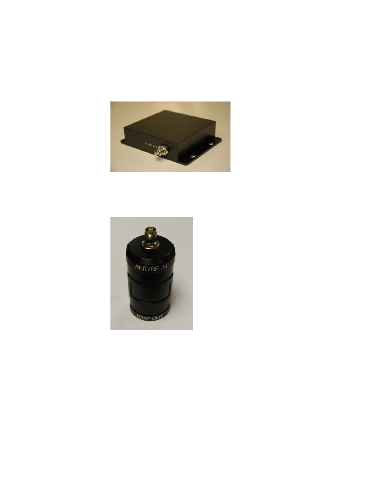
The picture below shows the two types of domo weatherproof down
converter.
L-Band and S-Band
Barrel down-converter
The Solo4 Receiver must be configured with the correct down-converter
Local Oscillator (LO) Frequency and down-converter LO side. These
numbers are specific to the type and frequency band of the downconverter.
The SOLO4 downconverter converts the received signal from
microwave frequencies to UHF frequency and applies gain allowing the
signal to run down cables without loss. This down-conversion allow
s
the domo SOLO Receiver to be mounted remotely from the receive
antennas. The down-converter is available as either a standard nominal
9dB gain model (DCB) or high gain variant (DCBX) nominal 19dB gain.
Page 24

24
Square down-converter
New Style Barrel down-converter
NOTE : The LO Frequency setting in the SOLO4 Receiver controller has
changed compared to the older square L-Band (1.1 to 1.4GHz) and S-Band
(2.28 to 2.55GHz) products. The LO frequency MUST be set absolutely
correctly for the system to work properly. This can be set using the Solo4
Receiver controller software – see section 3.3 of this manual for details on
use of the controller.
RF Parameters
L-Band
DC-100140
S-Band
DC-225265
Frequency In
1000MHz
to
1500MHz
2250MHz
to
2650MHz
Local Oscillator
1700MHz
1880MHz
High Side or Low Side
High
Low
Gain (DC variant)
9dB
9dB
Gain (DCX variant)
19dB
19dB
RF Parameters
L-Band
DCB-100150
L-Band
DCB-150200
S-Band
DCB-200250
S-Band
DCB-250300
3GHz
DCB-300350
C-Band
DCB-450500
C-Band
DCB-550600
Frequency In
1000MHz
to
1500MHz
1500MHz
to
2000MHz
2000MHz
to
2500MHz
2500MHz
to
3000MHz
3000MHz
to
3500MHz
4500MHz
to
5000MHz
5500MHz
to
6000MHz
Local Oscillator
1800MHz
2300MHz
1700MHz
2200MHz
2700MHz
4200MHz
5200MHz
High Side or
Low Side
High
High
Low
Low
Low
Low
Low
Gain (DCB
variant)
9dB
9dB
9dB
9dB
9dB
9dB
9dB
Gain (DCBX
variant)
19dB
19dB
19dB
19dB
19dB
19dB
19dB
Page 25
25
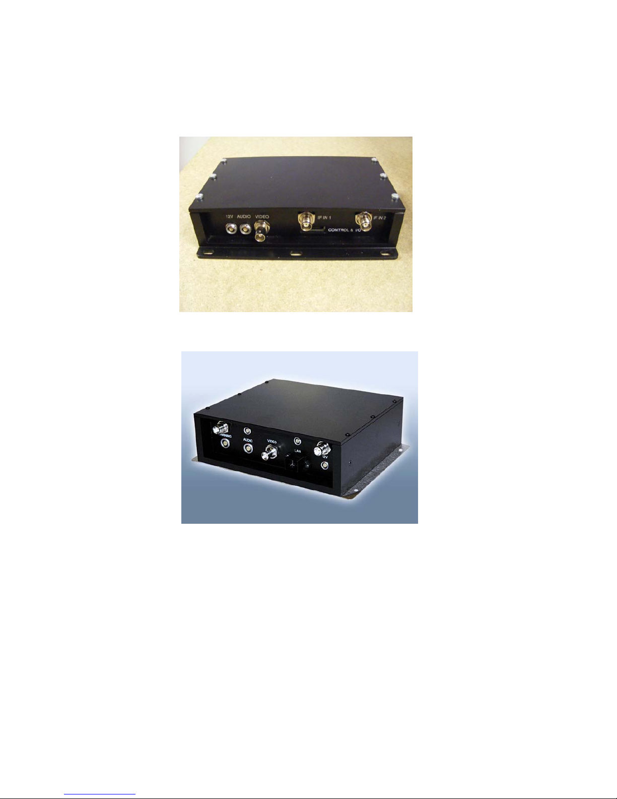
There are two styles of domo SOLO receiver box shown below.
domo SOLO receiver with Box style 1.
domo SOLO receiver with Box style 2.
Page 26
26
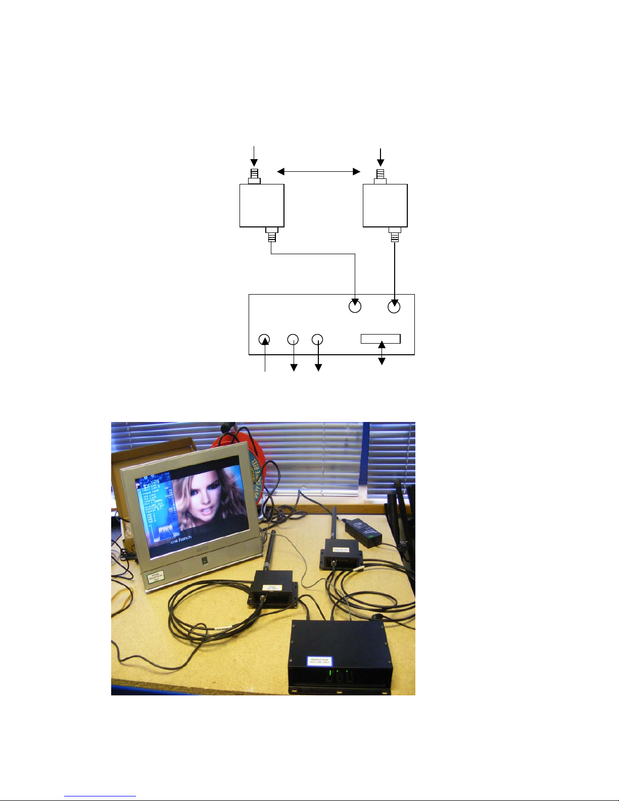
The domo SOLO2/4 receiver system with panel style 1 should be
connected as shown below.
IF In1
IF IN2
DC
Audio
Video
Control, data and
Chaining
Antenna 1
Antenna 2
3m TNC Cable
3m TNC Cable
DC
Cable
Video
Cable
Audio
Cable
100 cm
Page 27
27
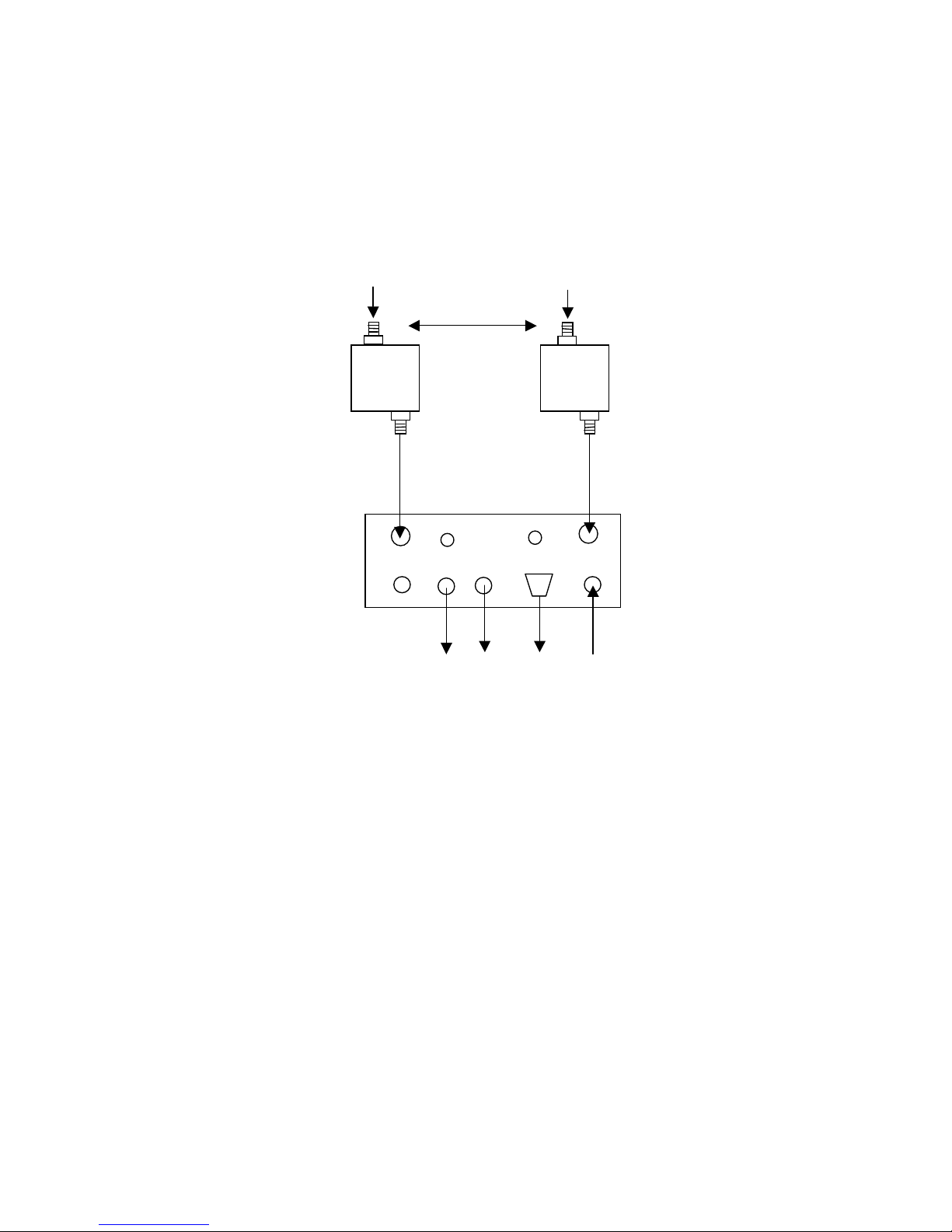
The domo SOLO2/4 receiver system with panel style 2 should be
connected as shown below.
IF In1
IF IN2
DC
Audio
Video
Control
Antenna 1
Antenna 2
3m TNC Cable
3m TNC Cable
DC
Cable
Video
Cable
Audio
Cable
100 cm
LAN
Cable
Chain
LAN
Data
Page 28

28
Diversity, Antenna Positioning and Use of Down Converters
Note: Domo down converters can be damaged by static electricity discharge when
connecting antennas. It is suggested that only antennas with built in DC path to ground
are employed to avoid static damage. If this can not be achieved then antennas should be
shorted to ground before connection to the down converter.
The domo SOLO2/SOLO4 receiver is a diversity receiver and will give
optimum results only when two antennas are deployed. The downconverter boxes should be connected to the receiver, by connecting the
3m TNC cables supplied between the down converter connector
labelled ‘RX / IF OUT’ and the receiver connector labeled ‘IF IN’. Care
should be taken not to over tighten the TNC connectors.
The down-conve
rters convert the RF signal down from microwave
frequencies to the UHF band, which allows the signals to be run along
longer cables without degradation. In the case of the standard domo
SOLO receiver 3 metre long cables are provided, allowing the downconverters to be positioned remotely from the receiver.
It is important that the down-converter be positioned very close to the
antenna - long cables sh
ould not be used between the antenna and the
down converter because this can degrade system performance.
Typically antennas and down converters will be positioned outside,
usually on the roof of a building or a vehicle. The down-converters can
be located outside, because they are weather proof. However the
receiver is not weather proof and the 3 metre cables should be used to
allow the receiver to be
positioned in an equipment room, rack or
housing.
The domo SOLO2/SOLO4 receiver uses an advanced diversity
technique called maximum ratio combining to construct a good
spectrum from two potentially damaged received signals. To get the
best results from diversity, the antennas should be physically separated
by at least 100cm.
Sometimes better results can be achieved by separating the antennas
further, or
by positioning them of different corners of a building. The
optimum antenna placement depends on the environment in which the
equipment is used and the signal path, and is often limited by physical
factors (accessibility for example).
The domo SOLO2/SOLO4 receiver is supplied without antennas since
the optimum choice of antenna will depend on the operational scenario.
For short range or mobile applicati
ons, omni directional antennas such
as ANT4L, ANT6C or ANT4S will be most suitable whereas for longer
range fixed links, or where mobile transmit activity is happening in a
defined 120 degree arc the higher gain ANT12L or ANT12S will be
more suitable.
Antennas should be screwed directly to the TNC input of the down
converter labeled ‘ANT/RF IN’.
Video Output Connection
Connect the video output lead to the BNC connector labeled ‘VIDEO’ on
the SOLO receiver and to the chosen video display device.
Page 29

29
Connector
Signal
Video BNC
75 ohm composite video output, PAL or NTSC
software selectable at the transmitter
Typically the video display device will be a high quality monitor.
Audio Connection
Push the LEMO connector into the socket labeled ‘AUDIO’, taking care
to align the connectors and connect the chosen audio output device.
Connector
Signal
Audio Plugs
Line level, +7dBu clip level, low impedance
source (20 ohm)
Typically the audio output device will be monitoring speakers.
DC Power
The SOLO2/SOLO4 Receiver is powered from a nominal 12V DC
supply.
As standard domo supply an AC to DC converter, terminated with a
LEMO connector on the DC power output. Push the LEMO plug into the
socket labelled ‘12V’, taking care to align the connectors. Connect the
AC adapter block to your local mains electricity supply, noting the mai
ns
supply requirements detailed on the adapter.
The 12V DC input has the following characteristics.
For Box style 1.
• Input Voltage Range – 9V to 16V, reverse voltage protected.
• Current Draw – 0.9A at 12V
For Box style 2.
• Input Voltage Range – 10V to 18V, reverse voltage protected.
• Current Draw – 1.0A at 12V
domo can supply optional bare DC power leads, for connection or
hardwiring to other DC source
s. The domo part number is CABDC3
Page 30

30
Control Cable
The control cable is used for connecting the SOLO receiver to a PC
when using the domo PC control application. The PC control
application is described in more detail the Advanced Operation section
of this handbook.
Data Connection
The SOLO receiver features a general purpose DATA port used for
outputting RS232 data transmitted from a SOLO2/4 transmitter.
Installation Notes
The domo SOLO receiver has been designed so that the downcon
verter units are mounted remotely from the receiver unit, and
connected via the 3 metre TNC cable.
The down-converter units should be connected directly to the receive
antenna, but where this is not possible a short length of low loss RF
cable such RG213C/U should be used. System performance will be
degraded by the introduction of RF losses at this point.
The down converter should be screwed or strapped
to a flat surface or
pole, using the integral mounting holes on the unit. The down converter
is weather proof, and has no special cooling requirements. If the downconverter is mounted where it is exposed to the weather then the
connector labelled ‘ANT / IN’ should face upwards.
The antenna itself should be separately secured, the TNC connectors
should not be expected to take the strain of the anten
na.
The domo SOLO2/SOLO4 receiver is designed to be mounted in an
equipment rack or shelter and must not be exposed to the elements.
The receiver is splash resistant, but is not waterproof, so it should not be
exposed to moisture for prolonged periods.
The receiver is self-cooling; however it should be mounted in a
ventilated environment. Forced air cooling is not required. Adequate
clearance on either
side the receiver (5cm) should be allowed for
ventilation.
The receiver is supplied with a mounting plate that allows the unit to be
screwed or strapped to a flat surface.
Page 31

31
7.4 Powering on the System
All external connection to the SOLO2/SOLO4 products should be made,
as described in the previous sections, before proceeding to power on
the system.
Applying power to the Solo Receiver
On powering the SOLO2/SOLO4 receiver, one of the eight green
configuration LEDs on the control panel will light (which one depends on
which configuration was active when the receiver was switched off).
The red Alarm LED may light if the receiver is unab
le to lock to a signal.
Applying power to the transmitter
When powering the transmitter directly from a 12V source, or from a
connected battery, the following will be observed.
If none of the LEDs on the control panel light then the transmitter may
be in standby mode. If this is the case then press, and hold the RF
button for more than one second.
One of the eight green configuration LEDs on the control panel will light
(which one depen
ds on which configuration was active when the
receiver was switched off).
The alarm LED may be lit, typically if there is no active video source.
Switch On RF on the transmitter
On the transmitter unit control panel, press the RF button briefly until the
RF LED lights. This indicates that the RF output is active, and that the
unit is transmitting.
If the receiver is able to receive the transmitted signal, the receiver RF
LED will ligh
t indicating receiver lock, and the receiver ALARM LED
should go out.
Video and audio signals will be presented automatically at the receiver
outputs.
Changing Configuration
domo SOLO2/SOLO4 equipment features eight user selectable and
programmable configurations. By default, all 8 configurations are set to
the values which are listed in Section 16, Default Configurations. The
configuration that is currently active is indica
ted by which of the eight
configuration LEDs is lit on the control panel. Pressing the ‘CONFIG
button on the control panel of any domo SOLO equipment will select the
next configuration in order.
On the SOLO transmitters, changing a configuration turns off the RF
output to prevent accidental transmission and potential interference. The
RF output must manually be re enabled once the user is confident tha
t
the correct configuration has been selected.
Modifying the default configurations is done from the PC control
application, as described in the section on Advanced Operation.
Page 32
32
Standby
Any of the SOLO2/SOLO4 transmitters can be placed in a low current
consumption standby mode by pressing and holding the RF button for
one second. The LEDs will go out indicating that the unit is in standby
mode.
Pressing and holding the RF button for one second brings the unit back
out of standby mode.
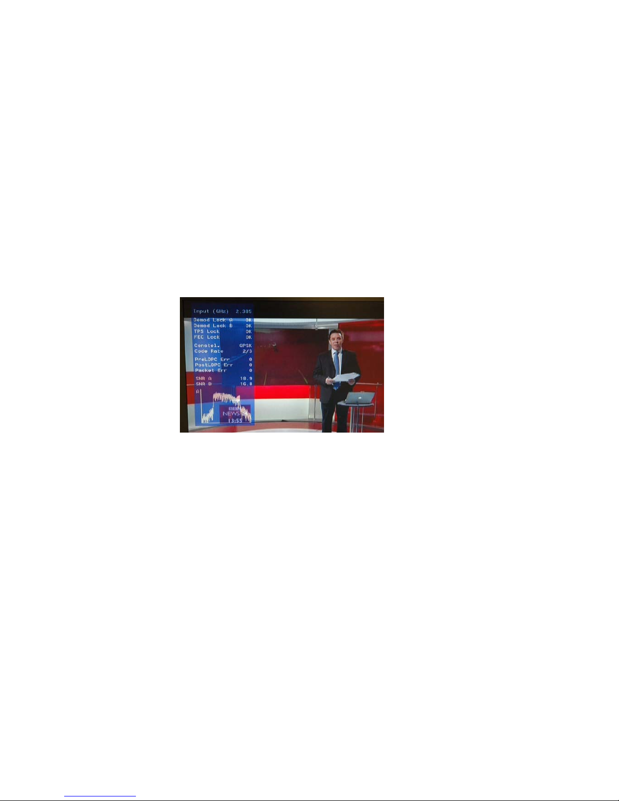
Diagnostic On Screen Display
The SOLO2/SOLO4 Receiver is equipped with a diagnostic on screen
display. This facility will ‘burn’ d
iagnostic data onto the video output for
test and set-up purposes. Pressing the RF button will enable this facility
and a diagnostic screen will appear in the video as shown below.
The displayed diagnostic data includes a spectrum display, signal to
noise data, input power level and frequency. The received spectrum
display is useful when checking for interference signals, the SNR
indicated signal quality. For more information on use of this facility a
domo training course is recommended and more information is available
in section 13 of this manual.
Using the OSD as a Set-up / Diagnostic Tool
The On Screen Display (OSD) is an extremely useful tool for system
set-up and diagnostic.
When setting a domo system up the OSD should be used in the
following way.
Check Channel is Clear
With the transmitter OFF, check that the channel is empty of
interference signals, this is confirmed by ensuring that the reported
power in the channel is at –99dBm and that the spectrum is shown as a
rounded dome with no obvious spikes or tones.
Chec
k Quality of Link
Switch on the transmitter and confirm that SNR is 6 or greater and that
power level is at least –92dBm or greater. This represents
Page 33

33
approximately a 5dB margin. Failure of the link will occur when the
power level reaches –97dBm or the SNR reaches 2dBm
Using the transmitter Range Mode Button
The Range Mode button and LEDs on the SOLO2/SOLO4 transmitter,
has the following function.
SOLO2 transmitter: No Function
SOLO4 transmitter: Selects the range of the transmitter.
On a SOLO4 transmitter, the user can select various range
characteristics, by repeatedly pressing the Range
Mode Button, these
can be toggled. The user should be aware that increasing the range will
have the effect of reducing the image quality and increasing the video
delay.
• Ultra Long Range: 1.25MHz QPSK FEC1/3 (optional) (Lowest
Image Quality)
• Long Range: 2.5MHz QPSK FEC1/3
• Medium Range: 2.5MHz QPSK FEC2/3
• Short Range: 2.5MHz 16QAM FEC2/3 (Highest Image Quality)
7.5 Domo Batteries and Battery Charging
Although domo equipment can be powered directly from user 12V
batteries, domo also supplies a rechargeable battery pack. The
following domo battery items are described in this section.
SOLBAT: 7.2V 4AH rechargeable NiMH battery pack.
SOLBCH: Battery Charger
SOLBCC: Adaptor cable that allows SOLBAT to connect to SOL2/SOL4
TX.
CONFIG
RF
1
2
3
4
5
6
7
8
RF
ALARM
MODE
Range Mode
Button
Ultra Long Range
Short Range
Page 34

34
Using the SOLBAT
The domo SOLBAT is used for powering domo transmitters.
The domo SOLOBAT can not be connected directly to the SOL2/SOL4
Transmitter, instead it must be connected using the SOLBCC adaptor
cable. The SOLBCC adaptor cable provides an interface between the 4
pin DC In Lemo on the transmitter and the 6 pin DC Out Lemo on the
battery. The cable is shown below.
When connected a fully charger SOLBAT will power the transmitter for
more than 4 hours.
Charging the SOLBAT
The SOLBAT can be recharged by connecting it to the SOLBCH battery
charger. The SOLBAT battery can be connected directly to the
SOLBCH battery charger, the interface cable is not required. When
connected the SOLBAT indicator LED has the following meaning.
LED Yellow: Battery not connected.
LED Orange: Battery fast ch
arging.
LED Green / Yellow flash: Battery ‘Top Off’ final charging
LED Green: Charging Complete / trickle charging
LED Orange / Green flash: Error
Approximately 2 hours should be allowed for a full charge of the
SOLBAT battery.
Page 35

35
7.6 Using the Clip On 1W Amplifier
Additional range can be achieved by connecting the SOLAMP1W clip
on amplifier to the domo SOLO2/SOLO4 transmitter.
Connections
This section describes how to connect the following model numbers.
• SOLAMP1W
The domo SOLAMP1W is supplied with the following cables:
• RF Cable (SMA to SMA semi-rigid bridge cable)
• DC Power Cable (with Control breakout)
• Lemo to Dtype control cable
Amplifier Connection
The domo SOLAMP1W is designed to mount directly onto the
SOL4/SOL2 transmitter. The following steps should be taken.
1. Screw the SOL2/SOL4 transmitter down onto the SOLAMP,
using the 4 screws provided.
2. Connect the RF output of
the transmitter (SMA) to the RF input
of the amplifier (SMA) using the short semi rigid SMA cable
provided. The SOLAMP is designed to work directly with the
SOL2/SOL4 transmitter.
3. Using the double-headed 16pin Hirose cable, connect one end
to the transmitter Hirose socket, and the other end to the
amplifier Hirose socket.
4. The 3 pin Lemo spur protruding from the double-headed Hirose
cable breaks ou
t the SOL2/SOL4 transmitter RS232 control
lines. The 3 pin male Lemo to Dtype cable should be
connected here when control of the transmitter from the RS232
PC application is required.
Page 36

36
The assembled system is shown below.
DC Power and Control Cable
The SOLAMP is powered by the SOL2/SOL4 TX and no additional
power is required. However the voltage range when using the SOLAMP
is more limited.
• Input Voltage Range: 11-16V, reverse voltage protected.
• Current Draw 1.2A (Includes SOL2/SOL4 TX) at 12V.
Antennas
Domo SOLAMP is supplied without antennas as standard. It is good
practice to ensure that an antenna is always connected before powering
the device. Pr
olonged operation without an antenna is not
recommended. The antenna should be connected by screwing it to the
TNC Type output connector with adapters as required, but care should
be taken not to over-tighten.
Note: It Is recommended that where possible antennas should be connected
directly to the SOLAMP. Use of cables will degrade performance.
Page 37

37
Installation Notes
The domo SOLAMP has been designed specifically for vehicle
applications, however it is a general-purpose amplifier and can be used
in many applications including the following.
• Vehicle applications
• Aircraft applications
• Long Range fixed links
Interconnection between the SOLAMP transmitter and the antenna, or
any intermediate optional power amplifier should be kept as short as
possible. Special atte
ntion should be taken to use only low loss cables.
An appropriate cable might be RG213C/U. It is essential to minimise the
distance between any amplifier and the antenna.
The SOLAMP is equipped with a self-regulating 12V input that can be
connected directly to the vehicle battery. Power conversion will be
required for 24V vehicles or 28V aircraft systems.
The SOLAMP is splash resistant, but is NOT water
proof, so it should not
be exposed to moisture for prolonged periods. The SOLAMP is selfcooling; however it should be mounted in a ventilated environment.
7.7 Using the booster 5W Amp
Additional range can be achieved by connecting the AMP5W-xxxxxx
booster amplifier to the domo SOLO2/SOLO4 transmitter.
Connections
This section describes how to connect the following model numbers.
• AMP5W-120140
• AMP5W-230250
The domo AMP5W-xxxxxx is supplied with the following cables:
• RF Cable
• DC Power Cable
Page 38

38
RF Connection
The domo AMP5W has the following input power requirements.
AMP5W-120140: Input Power 100mW or 20dBm
AMP5W-230250: Input Power 10mW or 10dBm
Therefore care must be taken when connecting the AMP5W-230250
product to either SOLO2 or SOLO4 transmitter. The output power of
the transmitter will need to be reduced when connecting to the AMP5W230250 amplifier, this can be done using the built in digital at
tenuator
using the PC Software GUI, or by fitting an RF attenuator in line.
Ideally when balancing the 5W Amplifier and domo transmitter a power
meter should be employed, this will give best results, because cable
losses can be factored.
Page 39

39
The amount of attenuation required is shown bellow.
Note the SOL4TXLE-138139 (1.389 to 1.399GHz), SOL4TXLE-240248 (2.4 to 2.483GHz),
SOL2TXLE-138139 (1.389 to 1.399GHz) SOL2TXLE-240248 (2.4 to 2.483GHz)must not
be connected to 5W PA, because these elevated power levels are not permitted in the
license exempt bands.
AMP5W-120140
AMP5W-230250
SOLO2 Transmitter
0dB Attenuation
10dB Attenuation
SOLO4 Transmitter
0dB Attenuation
10dB Attenuation
If customers are concerned about balancing the input power when connecting 5W
amplifiers, then they should contact domo directly.
DC Power
Push the connector on the DC power cable into the socket labelled
‘12V, taking care to align the connectors. Connect the banana
connectors on the other end of the cable to a suitable DC source.
The 12V DC input has the following characteristics.
• Input Voltage Range – 12V +/- 1V, reverse voltage protected.
• Current Draw 7.5A AMP5W-230250, 2.5A AMP5W-120140
Antennas
domo 5W Amp is supplied without antennas as standard. It is good
practice to ensure that an antenna is always connected before powering
the device. Prolonged operation without an antenna is not
recommended. The antenna should be connected by screwing it to the
N Type output connector with adapters as required, but care should be
taken not to over-tighten.
Note: It Is recommended that where possible antennas should be connected
directly to the 5W Amp. Use of cables will degrade performance.
Page 40

40
Installation Notes
The domo 5W AMP has been designed specifically for vehicle
applications, however it is a general-purpose amplifier and can be used
in many applications including the following.
• Vehicle applications
• Aircraft applications
• Long Range fixed links
Interconnection between the 5W AMP transmitter and the antenna, or
any intermediate optional power amplifier should be kept as short as
possible. Special atte
ntion should be taken to use only low loss cables.
An appropriate cable might be RG213C/U. It is essential to minimise the
distance between any amplifier and the antenna.
The 5W AMP is equipped with a self-regulating 12V input that can be
connected directly to the vehicle battery. Power conversion will be
required for 24V vehicles or 28V aircraft systems.
The 5W AMP is NOT splash resistant, and is NOT w
aterproof, so it
should not be exposed to moisture for prolonged periods. The 5W AMP
is self-cooling; however it should be mounted in a ventilated
environment. Forced air cooling is employed in the 5W AMP.
Page 41

41
8 Advanced Operation
8.1 SOLO System PC Controller Application Software
Advanced control of the SOLO2/SOLO4 system is available by using
PC control applications.
Typically users may want to customize the default configurations to
control settings such as frequency, scrambling keys, modulation
parameters, and video resolution.
• The SOLO2 and SOLO4 transmitter products are controlled by the
solo_tx_ctrl.exe application available on the CD delivered with the
product.
• The SOLO2 and SOLO4 receiver is controlled by the solo_rx_ctrl.exe
application available on the CD delivered with the product.
Note that exact file names may change as software version information is a part of domo
file names.
A PC is required with two RS232 Serial COM ports to control both a
transmitter and receiver simultaneously. Where changes are to be made
to either a transmitter, or a receiver, at different times, a PC with a single
RS232 Serial COM part can be used.
Installation of the two control programs is as simple as copying them
from the CD to a suitable location on the PC. No install shield routine is
launched.
Note that the controllers generate their own log and
initialisation files, so it is best to create a dedicated directory for these
applications, perhaps with links to the applications from the desktop of
the PC.
Use the supplied cables to connect the chosen COM port(s) of the PC
to unit(s) to be configured.
Launch each application in turn by double clicking or using the run
command.
Connection with a SOLO
product should be automatic, but the user can
force selection of the correct COM port using the drop down, followed by
the “Connect” button.
Errors such as the following may appear during the connection process
if the PC is unable to automatically ascertain which unit is connected to
which COM port.
• Error attempting to read invalid address
• Error has occurred during polling, polling has been disabled
Page 42

42
For both controllers, changes can be made to the unit configuration
using the drop down and data entry fields.
Changes are only applied to the unit when the “Apply” button is clicked.
Current values, as running in the unit, can be read using the “Refresh”
button.
Parameters that are status information only appear in greyed in the
application.
Further engineering and configuration controls can be found wi
thin the
“Options” and “File” drop down menus in the application title bars.
Page 43

43
8.2 Transmitter Control Application
The ‘Advanced’ button allows the user to navigate to the controller page
which exposes all available Transmitter settings.
Output Frequency (MHz)
The transmit frequency can be changed by entering the new desired
frequency in this field. Values outside the range supported by a
particular transmitter type will be rounded to the highest of lowest
supported frequency as appropriate.
The transmit frequency can be set in step size
s of 250kHz.
Engineering
Menu
Polling
Enable
Set Polling
Options
Enter an
Encryption
Key
Enter a
Licence key
Restore
Factory
Connectivity
Status
Video alarm
RF Output
Toggle &
status
Current
selected
Config
All parameter
changes must
be applied
Page 44

44
Bandwidth Mode
The Bandwidth Mode switches the unit between either domo
Narrowband (2.5MHz or 1.25MHz channel bandwidths) or DVB-T 8MHz
bandwidth. To select 6MHz and 7MHx DVB-T modes the user must first
click on ‘Advanced’ to enter the Advanced setting page.
Audio
Turns ‘On’ or ‘Off’ a basic audio setting – the audio settings are
optimised considering the bit-rate of the selected Transmit mode. The
user can set there own
audio settings using the ‘Advanced’ page, if
required.
Default Transmit Mode
In Narrowband the user has the following pre-defined modes available
from the main window. Note that the Ultra Long Range Mode is only
available to users who have purchased the SOLO4TXUP option
(1.25MHz and MPEG-4 modes). The user can of course define their
own specific FEC, bandwidth and modulation requirements from the
‘Advanced’ page.
Ultra Long R
ange: 1.25MHz QPSK FEC 1/3 (optional)
Long Range: 2.5MHz QPSK FEC 1/3
Medium Range: 2.5MHz QPSK FEC 2/3
Short Range: 2.5MHz 16QAM FEC 2/3
In DVB-T the available modes are
QPSK _ FEC 8MHz 1/32 Guard Interval
QPSK _ FEC 8MHz 1/32 Guard Interval
16QAM _ FEC 8MHz 1/32 Guard Interval
Scrambling
If the AES scrambling option has been purchased for the SOLO2 or
SOLO4 system in use, then it is possible to encrypt the link.
Scrambling
must be enabled at the transmitter by selecting either AES128 or AES
256 in the scrambling field. The actual scrambling key can then be
entered by clicking on the yellow ‘key’ icon.
File Options
Load Config – used for loading a single configuration data from text file.
Save Config - used for saving configuration data to text file.
Load Config Set – used for loading all 8 configurations from a text file
Sa
ve Config Set - used for saving all 8 configurations to a text file
Page 45
45
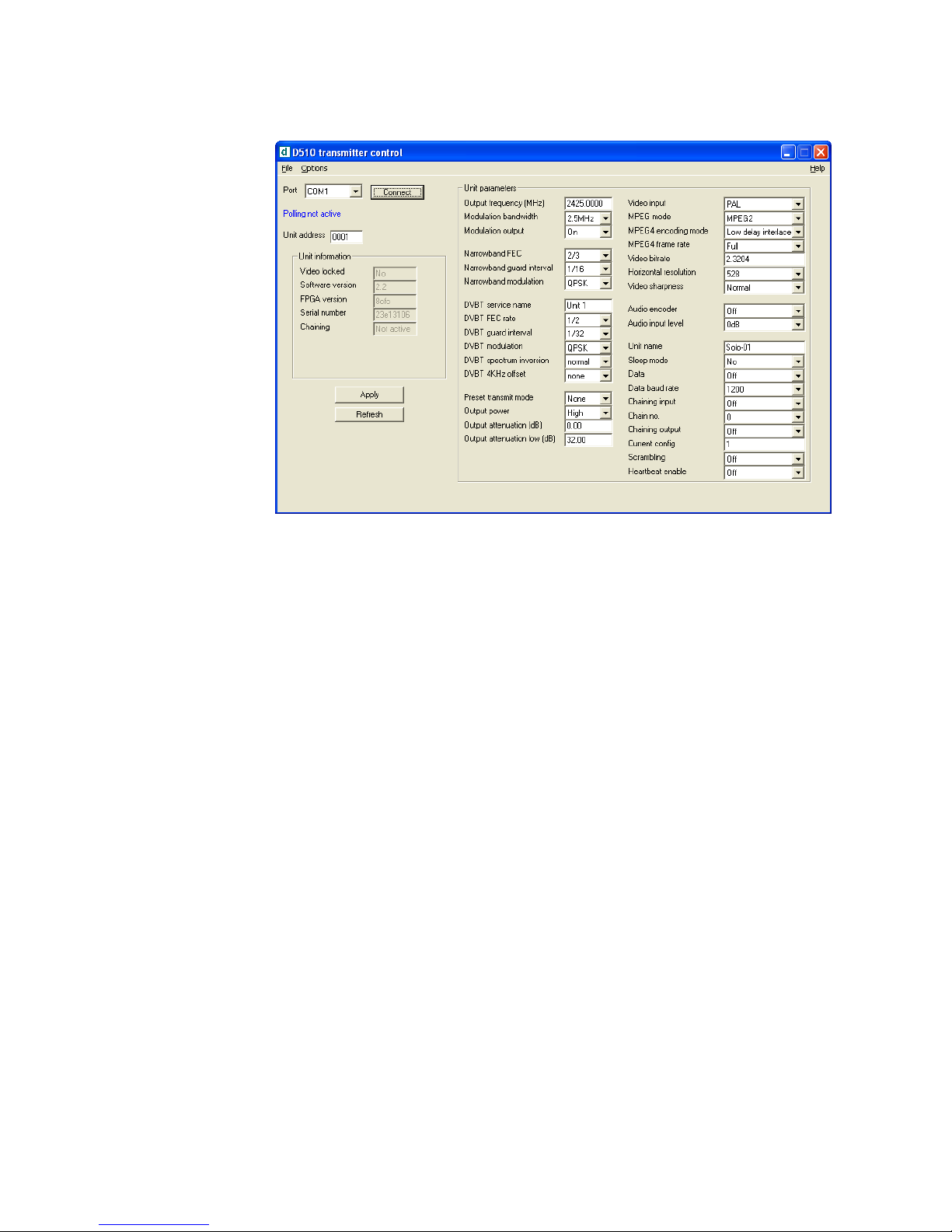
Advanced TX Controller Window
Output Frequency (MHz)
The transmit frequency can be changed by entering the new desired
frequency in this field. Values outside the range supported by a
particular transmitter type will be rounded to the highest of lowest
supported frequency as appropriate.
The transmit frequency can be set in step sizes of 250kHz.
Modulation Bandwidth
For the SOLO2 transmitter products, the modulation bandwidths 8, 7 or
6MHz can be selected.
For the SOLO4 tran
smitter products, the modulation bandwidths 8, 7, 6
or 2.5MHz can be selected. If the Ultra Narrow band upgrade has been
purchased the 1.25MHz will also be available to select.
The normal mode of operation is 2.5MHz.
Modulation Output
This control is used to turn on and off the RF output. After a
configuration change, the output always reverts to OFF.
Page 46

46
Narrow Band FEC
This option applies to SOLO4 transmitters only. The default FEC is 2/3,
however improved range operation can be achieved by selecting FEC
1/3. FEC 1/3 will improve signal range by 3dB. However FEC 1/3
reduces link capacity to 1.2Mb/s therefore reducing picture quality.
FEC
Link Bitrate
Sensitivity
2/3
2.4Mb/s
-99dBm
1/3
1.2Mb/s
-102dBm
Narrow Band Guard Interval
This option applies to SOLO4 transmitters only. The Guard Interval
defaults to 1/16. Interval 1/8 is also available for very long range
(aircraft downlinks) applications.
Narrow Band Modulation
This option applies to SOLO4 transmitters only. The COFDM mode can
be changed between QPSK and 16QAM. QPSK is the default mode
and will give the strongest most rugged RF link performance. Selecting
16QAM reduces the link performa
nce by 5dB but improves the link data
throughput, giving significantly better video quality.
Note: The terminology DVB-T refers to the 8,7,6MHz wide bandwidth modulation
employed in the SOLO2 products. The SOLO4 product is also capable of DVB-T, but this
mode is not recommended for normal operation
DVB-T Service Name
Applicable in DVB-T mode only, defaults to Unit 1. This should not be
changed in normal operation
DVB-T FEC
Applicable in DVB-T mode only, the default FEC is _. Other FEC rates
will all reduce the range of the product, but will improve image quality
and capacity of the link.
Page 47

47
DVB-T Guard Interval
Applicable in DVB-T mode only. The Guard Interval defaults to 1/32.
Other guard intervals such as 1/16 or 1/8 are available for very long
range (aircraft downlinks) applications.
DVB-T Modulation
Applicable in DVB-T mode only, the COFDM mode can be changed
between QPSK, 16QAM and 64QAM. QPSK is the default mode and
will give the strongest most rugged RF link performance. Selecting
16QAM reduces the link performance
by 5dB but improves the link data
throughput, giving significantly better video quality.
Output Attenuation
This control can be used to make minor adjustments to the output
power level, but in normal operation should be disregarded.
Video Input
This control is used to select the composite video input standard.
Options are PAL, and NTSC both with and without 7.5 IRE pedestal.
MPEG Mode
The default encoding mode is MPEG2, however for SOLO4 products if
the Ultra Narrow Band upgrade has been purchased, then MPEG4 will
also be available. It is recommended that MPEG4 be employed when
the unit is operating at low bitrates (2.5MHz bandwidth FEC1/3 or
1.25MHz bandwidth FEC1/3).
MPEG2 GOP Length
By default MPEG2 GOP length is set to a low delay stripe refresh mode.
This option allows the user to set the GOP length for a standard GOP
structure at the expensive of a
n additional delay.
MPEG4 Encoding Mode
This option is only available on SOLO4 products installed with the Ultra
Narrow Band Upgrade. This defaults to low delay interlace. Other
modes are available but advice should be sought from domo before
selection.
MPEG4 Frame Rate
This option is only available on SOLO4 products installed with the Ultra
Narrow Band Upgrade. This option allows the user to select lower
frame rate encoding (1/2 frame
rate, _, 1/8 etc) It is recommended that
Page 48

48
MPEG4 reduced frame rates be employed when the unit is operating at
low bitrates (1.25MHz bandwidth FEC1/3).
Video Bitrate
This control can be used to set the video bitrate within the constraints of
capacity available in the channel, but only when “Chaining Input” is set
to ON.
For normal SOLO transmitters, chaining CANNOT be enabled, and as
such video bit rate control is automatic.
The video bit rate is automaticall
y maximised in each configuration
when “Chaining Input” is turned off.
Horizontal resolution
The video coding resolution can be selected from 704, 528, 480 and
352 pixels. Changing the horizontal resolution to lower values will make
the coded picture softer.
Care should be taken to match the horizontal resolution to the resolution
of the camera connected to the transmitter; this will give best image
results.
Audio Encoder
The Audio can be turned on and off with this control. Audio is OFF by
default, but there are several audio modes that vary from very high
quality to speech grade that can be selected with this control. Enabling
audio will degrade the video quality, because some of the available data
capacity is diverted away from video to audio. Selecting high fidelity
audio modes will degrade the video quality more than lower fidelit
y
audio modes. The Audio encoder can also be switched to 32 kHz and
48 kHz MPEG Layer 1 modes; from software V3.3 upwards.
Note: The Solo4 receiver only supports 48 kHz sampling in MPEG Audio mode
and bit-rates in the range 192 to 448kbits/s.
Audio Input Level
This control is used to define the audio gain to be applied to the audio
input signal. 0dB is used for line level audio and various options up to
48dB of gain can be applied for microphone inputs.
Unit Name
This field allows the user to enter an identifier for the service that they
wish to transmit. This must match that selected at the receiver for the
service to be decoded. The unit name can be constructed of
any eight
ASCII characters.
Page 49

49
Sleep Mode
This control allows the unit to be forced into a Sleep Mode where main
functions are disabled, and the power consumption is significantly
reduced.
Data
With this ON / OFF control the user can select whether the transmitter
passes serial RS232 data across the RF link to the receiver.
Data Baud Rate
This field is used to select the baud rate of any RS232 serial data
component to be passed from the transmitter to the recei
ver across the
RF link.
Chaining Input
This control is not used in current SOLO products.
Chain Number
This control is not used in current SOLO products.
Current Config
This field reports the last loaded configuration number. Note that for the
SOLO transmitter, changes applied after the configuration has been
loaded are saved immediately into the current configuration.
Scrambling
If the AES scrambling option has been purchased for the SOLO2 or
SOLO4 syst
em in use, then it is possible to encrypt the link. Scrambling
must be enabled at the transmitter by selecting either AES128 or AES
256 in the scrambling field. At this point the user will need to ensure that
the correct key is in use and this is done by using Options / Write AES
Key.
The key is a 128bit key for AES128 and a 256bit key for AES256 and is
entered as either 32 or 64 ASCII hexadecimal cha
racters (0..F).
Video Locked (Status Only)
This status information indicated whether the transmitter is successfully
locked to the incoming composite video signal. Unlocked status may
indicate cabling faults, or poor quality incoming video feeds to the unit.
Page 50

50
Software Version (Status Only)
This status information describes the version of the software running the
SOLO transmitter product.
FPGA Version (Status Only)
This information is for domo engineering use only.
Serial Number (Status Only)
This status information is the electronic serial number of the transmitter
PCB. This number can be exchanged with domo to purchase extra
licensable features, such as upgrades to support AES encryption.
Chaining (Status Only)
This field reports the status of the chaining input to the SOLO
transmitter, and is not active in current units.
Options
Engineering – provides access to further diagnostic and calibration
features. The Diagnostic and Power calibration pages must not be
altered. The Advanced Options under the Engineering menu allow the
user to Change RS232 address, which can be useful when connecting
multiple units together via a multi drop RS485 bus for control purposes.
The
Serial control dialogue box allows the user to change timeouts
used during the serial communications between the unit and the
controller.
Enable Polling – selecting this option makes the control application
automatically refresh the data presented to the user every few seconds.
Polling Options – selecting this option allows the user to define
parameters to be regularly polled.
Write Encryption Key – ope
ns a dialogue box for entering an ABS or
AES scrambling key, as 32 ASCII hexadecimal characters (0…F)
Write License Code – open a further box for entering license codes for
the activation of licensable features (e.g. AES scrambling) in the
transmitter. Contact domo for support in applying new licenses as
required.
Restore Defaults – restores factory default settings in the transmitter.
File
Set Icon Source, Set logo source, Set logo size and Set application
title – allow the user to define a controller branding
Exit – exits the SOLO receiver control application
Page 51

51
8.3 Receiver Control Application
The ‘Advanced’ button allows the user to navigate to the controller page
which exposes all available Transmitter settings.
Engineering
Menu
Polling
Enable
Set Polling
Options
Enter an
Encryption
Key
Enter a
Licence key
Restore
Factory
Connectivity
Status
Green if the demodulator
has locked (found) a
signal at the frequency
Green if the received
signal quality is good
enough to provide an
‘error-free’ video
Green if the decoder is
decoding a valid MPEG
stream
All parameter
changes must
be applied
Current
selected
Config
Page 52

52
Bandwidth Mode (Narrowband or DVB-T)
The Narrowband and DVB-T radio selections switch the unit between
either domo Narrowband (2.5MHz or 1.25MHz channel bandwidths) or
DVB-T 8MHz bandwidth. To select 6MHz and 7MHx DVB-T modes the
user must first click on ‘Advanced’ to enter the Advanced setting page.
Input Frequency (MHz)
The receive frequency can be changed by entering the new desired
frequency in this field. Values outside the range supported by a
particula
r transmitter type will be rounded to the highest of lowest
supported frequency as appropriate.
The receive frequency can be set in step sizes of 250kHz.
Service Name
This field allows the user to enter an identifier for the service that they
wish to receive. This must match that selected at the transmitter (Unit
name) for the service to be decoded. The service name can be
constructed of any eight ASCII characters.
Descrambling
If the AES scrambling option has been purchased for the SOLO2 or
SOLO4 system in use, then it is possible to decrypt the link.
Descrambling must be enabled at the receiver by selecting either
AES128 or AES 256 in the descrambling field. The actual descrambling
key can then be entered by clicking on the yellow ‘key’ icon.
File Options
Load Config – used for loading a single configuration data from text file.
Save C
onfig - used for saving configuration data to text file.
Load Config Set – used for loading all 8 configurations from a text file
Save Config Set - used for saving all 8 configurations to a text file
On a receiver there are 8 separate configurations for Narrowband and 8 separate
configurations for DVB-T.
Page 53

53
Advanced RX Controller Window
Note: The terminology DVB-T refers to the 8,7,6MHz wide bandwidth modulation
employed in the SOLO2 products. The SOLO4 product is also capable of DVB-T, but this
mode is not recommended for normal operation
Narrowband / DVB-T
The SOLO2 is capable of receiving transmission in 6/7/8MHz wide
DVB-T OFDM only. The SOLO4 receiver is capable of receiving
transmissions in Narrowband and DVB-T. For receiving the
transmissions from a SOLO2 transmitter the ‘DVB-T’ radio button
should be selected. For receiving the transmissions from a SOLO4
transmitter the ‘Narrowband’ radio button should be selected.
When the ‘Narrowband’ radio bu
tton is selected, then the ‘Narrowband’
column of parameters will become highlighted, and can be set.
If the ‘DVB-T’ radio button is selected, then the ‘DVB-T’ column of
parameters will become highlighted, and can be set.
Input Frequency
The receive frequency can be changed by entering the new desired
frequency in this field.
Page 54

54
Down converter LO
This field allows definition of the local oscillator frequency in the
connected downconverters.
For domo supplied downconverters, this should be set as follows:
• 1880MHz for S band transmissions (2.28 to 2.55GHz)
• 1700MHz for L band transmissions (1.15 to 1.4GHz).
Down converter LO side
This field allows definition of the local oscillator side.
For domo supplied downconverters, this should be set as follows:
• LOW for S ba
nd transmissions (2.28 to 2.55GHz)
• HIGH for L band transmissions (2.28 to 2.55GHz)
OFDM Bandwidth
This field displays the width of the received OFDM signal and should be
set to 2.5MHz for normal SOLO4 system operation, and should be set
to 8MHz for normal SOLO2 system operation.
OFDM Guard Interval
In this field the user selects the guard interval which matches the
transmitter. For SOLO4 systems typically a guard interval of 1/16 is
used, however on very long range transmissions a guard interval of 1/8
may be employed. For SOLO3 systems typically a guard interval of
1/32 is used, however on very long range transmissions a guard interval
of 1/8 may be employed.
OFDM Mode (Status Only)
This field displays the COFDM constellation that is being demodulated
at the receiver. In normal operation this will match that selected at the
transmitter.
OFDM FEC (Status Only)
This field displays the COFDM FEC (Forward Error Correction) that is
being demodulated at the receiver. In normal operation this will match
that selected at the transmitter.
Input SNR (Status Only)
For each IF input, the SNR (Signal to Noise Ratio) is reported. Values in
the order of 18dB to 22dB represent strong received signals, whilst
values in the order of 5dB represent poor received signals which will
likely give rise to decoding error
s.
Page 55

55
BER Pre Viterbi (Status Only)
This figure is for engineering use and gives a representation of the error
rate prior to the error correction techniques having been applied in the
receiver.
BER Post Viterbi (Status Only)
This figure gives a measure of the bit error rate after error correction
techniques have been applied in the receiver. Any numbers greater than
0 in this field indicate the presence of un-correctable errors in the
received stream, and thus pictur
e glitching and audio artefacts will
occur.
Input Level (Status Only)
This figure indicates the received signal level at the two receiver inputs.
Normal Operation will occur when the input level is between –15 and
–90 dBm. Signals greater than –15 may be too powerful and cause
damage. Signal less than –90dBm may be too weak and cause picture
loss (typical link failure will occur between –95 and –99dBm).
Demod Lock Status (Status Only)
This indicates whether the demodulators are successfully locked to the
RF signal.
Data
With this ON / OFF control the user can select whether the receiver
extracts any data component that may be in the transmitted stream.
Such data components are presented at the receiver DATA output port.
Data Baud Rate (Status Only)
This field reports the baud rate of any RS232 serial data component that
is present and selected in the stream.
Input Line Standard (Status Only)
This field reports the line standard that is currently being, or last was,
decoded.
Power Up Line Standard
Using this field the user can select what line standard of video the
receiver will output (PAL / NTSC) when the receiver is first powered on
and before it has locked to an incoming RF signal.
Page 56

56
NTSC Mode
With this control, when running in 525 line mode, the user can select
whether the NTSC composite output video has a 7.5 IRE pedestal
applied.
Blue Screen on Fail
When the link fails, the user can select between a blue field video output
(YES), and a freeze frame (NO) with this option.
Unit Name
This field allows the user to enter an identifier for the service that they
wish to receive. This must match that selected at the transmi
tter for the
service to be decoded. The unit name can be constructed of any eight
ASCII characters.
Descrambling
If the AES scrambling option has been purchased for the SOLO system
in use, then it is possible to encrypt the link. Descrambling must also be
enabled at the receiver by selecting AES128 or AES256 in the
descrambling field. At this point the user will need to ensure that the
correct key is in use at the
receiver and this is done by selecting
Options / Write AES Key in the receiver controller.
The key is a 128bit value for AES128 and a 256bit value for AES256,
and is entered as 32 or 64 ASCII hexadecimal characters (0...F).
Decoder Lock Status (Status Only)
This field reports whether the video decoder is successfully locked to the
incoming digital bit stream.
Current Config
This field allows the user to select which of the 8 memory configs the
recei
ver is operating in. The receiver has 8 stored configurations and
the user can move between them by setting the appropriate number in
this field. Changes made to other settings by the user will automatically
be stored in the configuration number indicated by this field.
Serial Number (Status Only)
This status information is the electronic serial number of the transmitter
PCB. This number can be exchanged with domo to purchase
extra
licensable features, such as upgrades to support AES decryption.
Page 57

57
Software Version (Status Only)
This status information describes the version of the software running in
the SOLO transmitter product.
FPGA Version (Status Only)
This information is for domo engineering use only.
Chaining
Chaining allows multiple services to be sent via one RF link. A receiver
may be connected to a transmitter to form a chaining or relay link. To
allow this, the chaining interfaces provided on the first receiver must be
connected to the second trans
mitter. Three modes of operation are
supported - no chaining (default), chaining mode, and relay mode. The
chaining mode allows two services (remote and local) to be combined.
The relay mode allows just the remote service to be transmitted turning
off the local service.
For chaining mode to operate correctly, the second unit in the chain
must operate at twice the transmit data rate from the first. If th
e first unit
is operating in QPSK rate 2/3 the second unit must operate in 16QAM
rate 2/3. If the first unit is operating in QPSK rate 1/3 the second unit
must operate in QPSK rate 2/3. The units must have different chaining
numbers selected, and the different unit names. For the relay mode to
operate correctly the second unit must have the transmit rate greater or
equal to the first unit.
Chaining is a
licensable feature.
Options
Engineering – provides access to further diagnostic and calibration
features. The Diagnostic dialogue box must not be altered. The
Advanced Options dialogue box under the Engineering menu allows
the user to Change RS232 address, which can be useful when
connecting multiple units together via a multi drop RS485 bus for control
purposes. The Serial control dialogue box allows the use
r to change
timeouts used during the serial communications between the unit and
the controller.
Enable Polling – selecting this option makes the control application
automatically refresh the data presented to the user every few seconds.
Polling Options – selecting this option allows the user to define
parameters to be regularly polled.
Write Decryption Key – opens a dialogue box for entering an ABS or
AES
scrambling key, as 32 ASCII hexadecimal characters (0…F)
Write License Code – open a further box for entering license codes for
the activation of licensable features (e.g. AES scrambling) in the
transmitter. Contact domo for support in applying new licenses as
required.
Restore Defaults – restores factory default settings in the transmitter.
Page 58

58
File
Set Icon Source, Set logo source, Set logo size and Set application
title – allow the user to define a controller branding
Exit – exits the SOLO receiver control application
Page 59

59
9 NETSTREAM IP Output Option
9.1 General Info
This section is relevant only to customers that have the NETSTREAM
option fitted in their SOLO2 or SOLO4 receiver.
The NETSTREAM can only be fitted in box style 2.
The NETSTREAM product features an RJ45 socket for connection to
10 Base T or 100 Base T Ethernet networks. The network interface
automatically switches between 10 Base T and 100 Base T as required.
The connector is wired for straight conne
ction to a network Hub and
does not automatically compensate for Ethernet crossovers. If a direct
connection to a PC is required, then an Ethernet cross over cable
should be used.
9.2 Streamer
The main use for the NETSTREAM card is to allow viewing of the
received video/audio signal on a standard PC (or laptop) running the
domo software decoder software (part number NETSWDR).
Data is transmitted over the Ethernet
network by means of “multicasting”
i.e. continuous real-time streaming of packets accessible to any PC
connected to the network.
It is therefore possible for more than once connected PC to view the
streamed data simultaneously.
Two types of multicast IP packets are streamed.
• Packets carrying video, audio and data as received by the unit;
• Packets known as Session Announcement Protocol and Sessions
Desc
ription Protocol data (SAP and SDP), which contain information
regarding the nature and location of the stream itself.
9.3 Web Server
The unit features a web server, which can be used to change the
configuration of the streaming parameters.
The default IP address of the unit when delivered is 192.168.0.71
A standard Internet browser can be used to reach the configuration
page of the unit.
The URL of the configuratio
n page is http://192.168.0.71/index.htm
Note that the address of the index page will change in the instance that the NETSTREAM
IP address is subsequently changed.
Page 60

60
To access the control page, the user is required to follow a login procedure.
When prompted, enter the following login details:
User Name: admin
Password: ipradio
The browser will display the page shown below:
Page 61

61
IP Address
This control allows the user to change the IP address of the unit. The
factory default value is 192.168.0.71.
The user should make a note of the unit’s new IP address when
changing it. Failure to do so will result in an inability to use the web
browser interface until the unit’s new IP address is recovered.
Multicast Address
This control allows the user to change the multicast address used by the
unit. The default valu
e is 239.16.33.254.
Port Number
This control allows the user to change the multicast port used by the
unit. The default value is 10000.
TTL
This control allows the user to change the value of the IP TTL (Time to
Live) set by the unit.
SAP Address
This control allows the user to change the value SAP/ SDP multicast
address used by the unit. The default value is 224.2.127.254 and the
port used is 9875. These are standard multicast
values for such
parameters, and it is recommended they are not changed unless
specifically required due to routing restrictions.
SAP / SDP Data
Note – SAP is Session Announcement Protocol and SDP is Session Description Protocol
as defined in RFC2327 and RFC2974
• Service Name – textual information naming the multicast stream as
delivered in the SAP/SDP packets from the unit. Default is “MPEG
Stream”
• Info – further textual information about the multicast stream as delivered
in the SAP/SDP packets from the unit. Default is “NetEng”
• Description - Optional URI (Universal Resource Identifier) pointing to a
web page on the network containing additional informati
on about the
multicast. Default is www.domo.co.uk
• Bitrate - textual information indicating the bitrate in kbits/s of the stream.
Default is usr kbit/s
Page 62
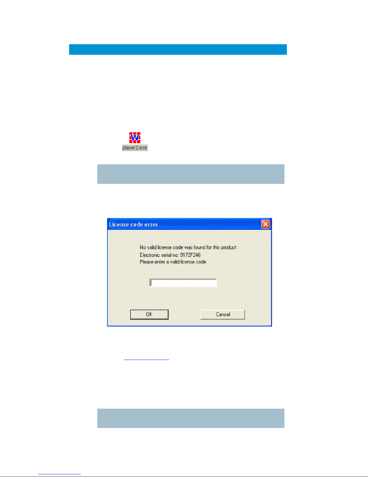
62
10 Software Decoder
10.1 General Information
The domo software decider application (part number NETSWDR) is
delivered on CD. The product is installed by following the prompts
offered by a comprehensive Install Shield.
The product is licensed, after installing the product from the Installation
shield the user should double click on the application icon, which may
appear as depicted below.
Note – later revisions of the software decoder may feature different icons or application
names.
When the application is executed, if the PC is unlicensed then the
following prompt box appears
Assuming the user has pre-paid for their Software decoder licence then
the user then simply needs to email the Electronic Serial number to
domo ([email protected]) quoting the pre-paid token number. After
receipt of this email domo will then provide a licence key. The licence
key should be entered into the prompt box in the application window
above which will licence the PC.
The license is tied to the target PC, and reinstallation of the product on a
different machine will require the purchase of further licenses from
domo.
Note – if a user has not purchased a pre-paid licence then the user will have to contact
domo sales to purchase a licence prior to receiving a licence code.
Page 63

63
The domo software decoder can decode and present MPEG streams
that are available from two sources.
• Multicast streams being played out on the connected network by a
NETSTREAM or NETCRXIPUP IP upgrade in the CRX.
• Files available locally on the target PC or network.
10.2 Decoding Multicast Streams
If the application is started on a PC, which is connected to a network
shared by the NETSTREAM or CRX IP stream, then it will present a
view of available streams that can be software decoded and viewed on
the PC.
The name of the multicast stream is listed in the window, alongside an
expandable crosshair. Clicking the crosshair presents the streams
multicast details and a list of any services contained within a stream:
Page 64

64
In the above example the stream “DVT Streaming” has a multicast
address of 239.16.33.253 and is streaming to port number 10000. It
contains two services, named “CRX-001” and “CRX-002”.
It can be seen that there is an expandable crosshair alongside each of
the service names. Clicking these provides more details about each
service:
In this case we see that the service “CRX-001” is unencrypted, uses
MPEG2 video encoding, and has single channel (mono) audio encoded
with an 8-bit companding scheme with a sampling rate of 16kHz.
Page 65

65
To start decoding a service the user should “double click” the
appropriate service name. Service names are always highlighted in bold
text in the main player window. If the service is unencrypted the main
decoder window will be launched.
10.3 Encrypted Streams
If the service selected is being encrypted by upstream hardware, then
the user will be prompted for the reciprocal key. The video stream player
can detect from infor
mation in the stream whether ABS or AES
encryption is being used. It will present a window appropriate to the type
of encryption. For ABS the following window will appear:
This requires the 32-bit ABS decryption key to be entered as 8
hexadecimal characters. This is not case sensitive.
Although the player is able to distinguish a service encrypted with AES,
it cannot detect whether 128-bit or 256-bit AES encryption has been
used. Therefore the following window will be presented to the user when
AES encryption is detected:
By default this window is expecting a 128-bit (to be entered as 32
hexadecimal characters) decryption key. If the service is encrypted with
AES256 encryption, the user should select this from the “Scrambling
Page 66

66
type” drop-down list in the window. The appearance of the window will
then change to the following:
The user can now enter the AES256 key in the two fields provided.
Once the key is entered, the main decoder window will be launched.
Page 67

67
10.4 Main Decoder Window
The main decoder window will appear as follows:
The title bar of the window presents the service name and the streams
multicast details. Below this there is a menu-bar with an Options drop-
down menu and a toolbar with some icons on it. Each of the icons
corresponds to a selection in the Options menu. The following
selections are available in the menu:
Record to file
This option gives the user the option of recording the file that is being
decoded to disk.
The user is prompted with a standard Windows “File Save” dialog box:
Page 68
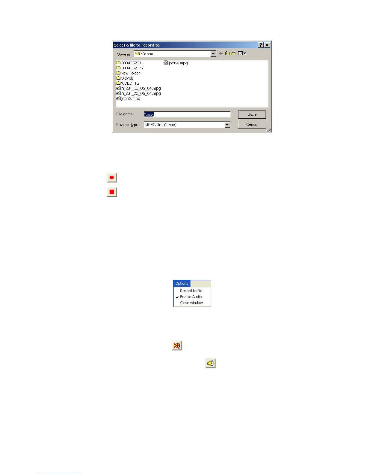
68
When recording is active, this menu option is changed to “Stop
Recording” which can be used to stop writing to disk.
Two buttons on the toolbar can be used to control recording:
to start recording
to stop recording
When recording is inactive, the stop recording button will appear greyed
out and unselectable. The start recording button will appear in similar
fashion when recording is active.
Enable audio
This option will only appear in the menu if the service has audio. When
more than one service includes audio only one window can decode
audio at any one time. When audio is enabled in a service, the enable
aud
io option will appear with a tick beside it in the menu:
Selecting this option simply toggles whether audio is enabled or
disabled. If another window was previously decoding audio it will be
forced to disable its audio as the new window is now the audio decoding
window.
When audio is enabled, the
button will appear on the toolbar.
Clicking this button will disable audio. When audio is disabled this button
will change its appearance and appear as
, clicking which will
enable audio.
Close window
This closes the main decoder window.
Page 69
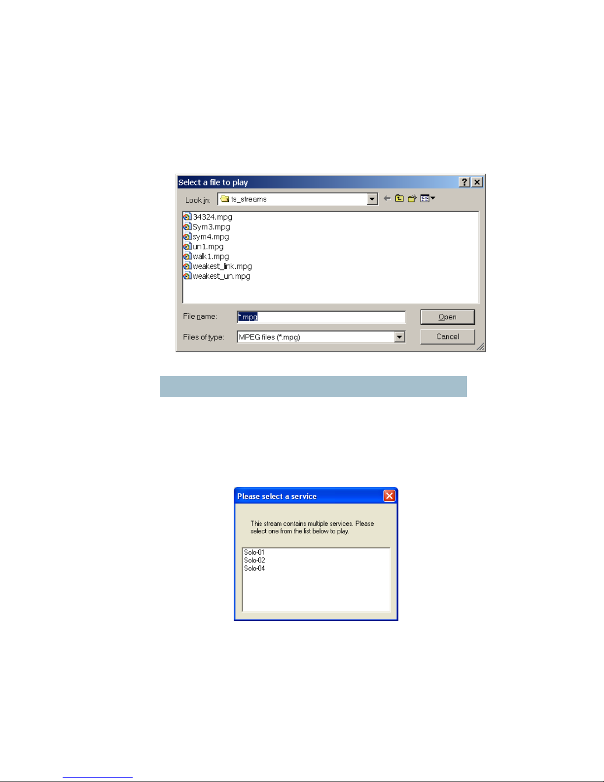
69
10.5 Decoding Locally Stored Files
If the user wishes to play a file from local storage (regardless of whether
multicast streams are available or not) then the “Play from File” button
on the main application window should be pressed.
This opens a standard Windows “Open File” dialog box to make the
selection.
Note - the default file extension is *.mpg.
The application will scan through the selected file for any services
available. If the stream contains only one service the application will
select this automatically and operation will be as described in the
preceding sections after a service is selected.
If there are multiple services in the file the application will present a popup window with a list of the services in:
The user should “double-click” the service they wish to decode.
Thereafter, operation is as described in the preceding sections.
10.6 Miscellaneous application options
The main application window has a menu-bar with an Options drop-
down menu. This presents the following selections:
Page 70

70
These options relate to the main application icon, which normally
appears as
and an optional logo. By default there is no logo
presented. The user may select a bitmap to appear as a logo below the
“Play from file” button on the main application window.
Selecting either the “Set icon source” or “Set logo source” options will
open a standard Windows file dialog box. For icon files, this is set to filter
for files with a .ico file extension. These are standard Windows icon files.
A 32 x 32 pixel icon is expected. For logo files, the dialog box is set to
filter for bitmap files with a .bmp file extension. The size of the bitmap file
is not important as the application will automatically make it fit to the
available space. The logo size can be altered by selecting the “Set logo
size” option in the menu.
Page 71

71
11 Fault Finding
11.1 Indicated Faults
SOLO2 Transmitter and SOLO4 Transmitter
LED Condition
Meaning
Action
ALARM LED lit
permanently
Unit alarm, likely to be
no video input lock
Ensure video source connected
and of correct video standard
(PAL/NTSC)
SOLO2 Receiver and SOLO4 Receiver
LED Condition
Meaning
Action
ALARM LED lit
RF LED off
No RF Signal Lock
Check a suitable RF source is active,
on correct frequency.
Ensure Downconverters are
connected.
Ensure antennas are connected to
downconverters.
Ensure there is no interfering signal.
ALARM LED lit
RF LED on
Has RF signal lock but no
decoder lock
Check video is enabled at the
transmitter.
Check correct unit name is selected
at the receiver to match the
transmitter.
ALARM LED lit
Lock LED lit
RF LED on
Has RF signal lock but no
decoder lock due to
encryption of video
Check that scrambling keys are
matched.
Check video is enabled at the
transmitter.
Page 72

72
11.2 Fault Symptoms
Symptom
Suggested Action
No RF Link
Check a suitable transmitter RF source is active, on correct frequency.
Ensure Downconverters are connected. Ensure antennas are
connected to downconverters. Ensure there is no interfering signal.
Poor link
performance
Poor performance of the link can occur for the following reasons.
• Interference. Should an interfering RF signal occur on the
same frequency the performance of the link will be affected.
Remove the interferer e or move to an alternative
frequency.
• Unsuitable antennas, or out of band antennas. See the
antenna sections for guidance on antenna selection and
use.
• Reduced transmit power, ensure that the attenuation
setting on the transmitter is appropriate for direct output, or
for amplifiers connected.
• Receive antenna positioning, were possible mount the
receive antennas away from other objects, unobstructed
and as high as possible. Poor alignment of directional
antennas.
• No Diversity operation. Ensure both down converters are
operational.
Blue screen
at receiver
Receiver RF LED not lit - see “No RF Link” section
Receiver RF LED lit. Check video is enabled at the transmitter. Check
correct unit name is selected at the receiver to match the transmitter.
Check scrambling keys are matched.
Reduced
Image
quality
Image quality is affected by the selected horizontal resolution. The
image will become progressively softer for each horizontal resolution
below the sharpest resolution of 704 pixels. It is advisable to select a
horizontal resolution that matches the resolution of the camera.
Image quality is also affected by the video bit rate which can be read
from the video bit rate field of the SOLO transmitter controller). The
standard setting is 2.3Mb/s. However enabling audio, particularly the
high quality audio modes, will reduce the video bit rate substantially.
Therefore ensure an appropriate audio mode is selected or audio is
fully disabled if not required.
No audio
Ensure audio is enabled at the transmitter (disabled by default).
Page 73

73
12 LED Indicators
SOLO2 Transmitter or SOLO4 Transmitter
LED / Button
Colour
Meaning / Use
Alarm LED
Red
When lit indicates alarm or fault condition on equipment. Usually
means no lock to incoming video.
Front Panel Lock
LED
Yellow
When lit indicates service is encrypted
RF LED
Green
Transmitter:
When lit indicates RF output is active.
LED 1 to 8
Green
Indicates which of the eight stored configurations is currently
selected.
Range Mode
LEDs
Green
SOLO2 Transmitter: These LEDs have no function
SOLO4 Transmitter: Indicates range mode
Ultra Long Range: 1.25MHz QPSK FEC1/3 (optional)
Long Range: 2.5MHz QPSK FEC1/3
Medium Range: 2.5MHz QPSK FEC2/3
Short Range: 2.5MHz 16QAM FEC2/3
SOLO2 Receiver and SOLO4 Receiver
LED Condition
Meaning
Red ALARM LED lit
RF LED off
No RF Signal Lock
Red ALARM LED lit
RF LED on
Has RF signal lock but no decoder lock
(stream probably encrypted with encryption
not selected at receiver)
Red ALARM LED not lit
No alarms
RF LED lit
RF signal lock
RF LED not lit
No RF signal lock
Single CONFIG LED lit
Indicates selected config
No CONFIG LEDs lit
Unit Off
Page 74
74
13 Receiver On Screen Display
The receiver on screen display is a useful diagnostic tool providing a
number of pages with different functionality.
• An Input Status page displaying simple data on the signal being
received such as frequency, range mode, signal strength and quality.
• An RF Advanced page displaying detailed data on the signal being
received such as lock statuses, modulation scheme, receiver settings
and error counts.
• An Engineering Data page displaying antenna input spectrum plots and
metadata if received from the transmitter.
• A Frequency Scanning page which can scan a frequency range and plot
signal strength showing noise free areas to place a transmitter
frequency. This can also automatically provide a list of decodable
services within that range.
• A GPS Overlay page displaying GPS time, date, position and fix type if
received from the transmitter.
13.1 Input Status Page
The Input Status page contains a simplified representation of the signal
being received.
Input Status
-----------Frequency & Mode:
2.50000 GHz
Ultra Long Range
Encryption:
CLEAR
Antenna Input A:
Signal Medium
Quality Excellent
Antenna Input B:
Signal .
Input Status
-----------Frequency & Mode:
2.50000 GHz
Ultra Long Range
Encryption:
CLEAR
Antenna Input A:
Signal .ooooOO
Quality Excellent
Antenna Input B:
Signal .
Input frequency and mode.
Signal mode description if a
standard range mode.
Bandwidth, constellation and
FEC rate if a non-standard
range mode.
Encryption status either
ENCRYPTED or CLEAR
when there is signal lock, or
Unknown with no lock.
Signal strength bar alternating
with description.
Description of signal quality.
Description of signal
strength alternating
with strength bar.
Antennas A and B are
shown here, if C and D
are available they
would be listed below.
Page 75

75
Signal Level Descriptions
Range (dB)
Description
Strength Bar
Less than -100
None
.
-100 to -95
Low
.o
-95 to -90
Low
.oo
-90 to -80
Medium
.ooo
-80 to -70
Medium
.oooo
-70 to -60
Medium
.ooooO
-60 to -50
High
.ooooOO
Greater than -50
High
.ooooOOO
Signal Quality Descriptions
Simplified quality descriptions are available for standard Short to Ultra
Long Range narrowband modes, and 8MHz DVB-T modes. Other
variations will just show a dB value.
Range (dB)
Description
0
Below Quasi Error Free margin
(dB value dependant on mode)
None
< 3dB above QEF margin
Poor
< 6dB above QEF margin
Good
> 6dB above QEF margin
Excellent
13.2 RF Advanced Page
The RF Advanced page contains detailed data on the signal being
received, as well as some receiver settings.
RF Advanced
----------Input(GHz) 2.50000
TPS Lock Yes
FEC Lock Yes
Constel QPSK
FEC Rate 1/3
G.Interval 1/16
AutoBW 1.25MHz
A: Input Lev. -74
SNR 21.5
Demod Lock Yes
B: Input Lev. -130
Input frequency, TPS
and FEC lock statuses,
constellation and FEC
rate.
Antenna input level,
SNR and demodulation
lock status.
Antennas A and B are
shown here, if C and D
are available they
would be listed below.
Error counts. Pre/post LDPC for
narrowband and Viterbi FEC for
DVB-T services.
Receiver Guard
Interval and Bandwidth
settings.
Page 76
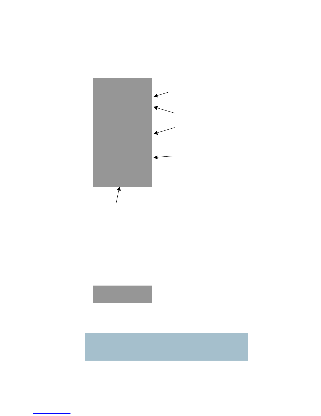
76
13.3 Engineering Data Page
The Engineering Data page contains antenna input spectrum plots,
along with GPS, temperature and video lock data received from the
transmitter.
13.4 GPS Overlay
The GPS Overlay is a small three lines of text over the top left of the
video. The text contains a time (UTC), date, longitude, latitude and fix
type as extracted from GPS data from a transmitter.
If “Data Disabled” is shown the Data configuration option n
eeds to be
turned On to receive transmitter data. If Data is disabled this page will
not appear whilst changing page via the front panel.
Note: For GPS data to appear on the OSD several conditions need to be met. A
compatible GPS receiver with NMEA output should be connected to the data port of a
transmitter. The transmitter must have Data enabled and the correct Baud rate set (usually
4800 for NMEA), and the receiver must have Data enabled.
14:06:59 24/07/09
Engineering Data
Antenna input frequency
spectrum plots. Input level
is shown at the top left of
each plot and SNR is
shown if available.
Antenna inputs A and
B are shown here. If C
and D are available
either A and B, or C
and D will be shown
depending on settings.
When setup correctly NMEA
GPS data can be collected
from a transmitter, and
coordinates are displayed
with their UTC time stamp.
If the time is not updating
frequently or the fix type
shows “No Fix” then the
GPS coordinates are the last
received at the time shown.
If “Data Disabled” is shown
the Data configuration option
needs to be turned On to
receive transmitter data.
If estimated case
temperature or video lock
status is received from a
compatible transmitter this
will be shown here.
Page 77
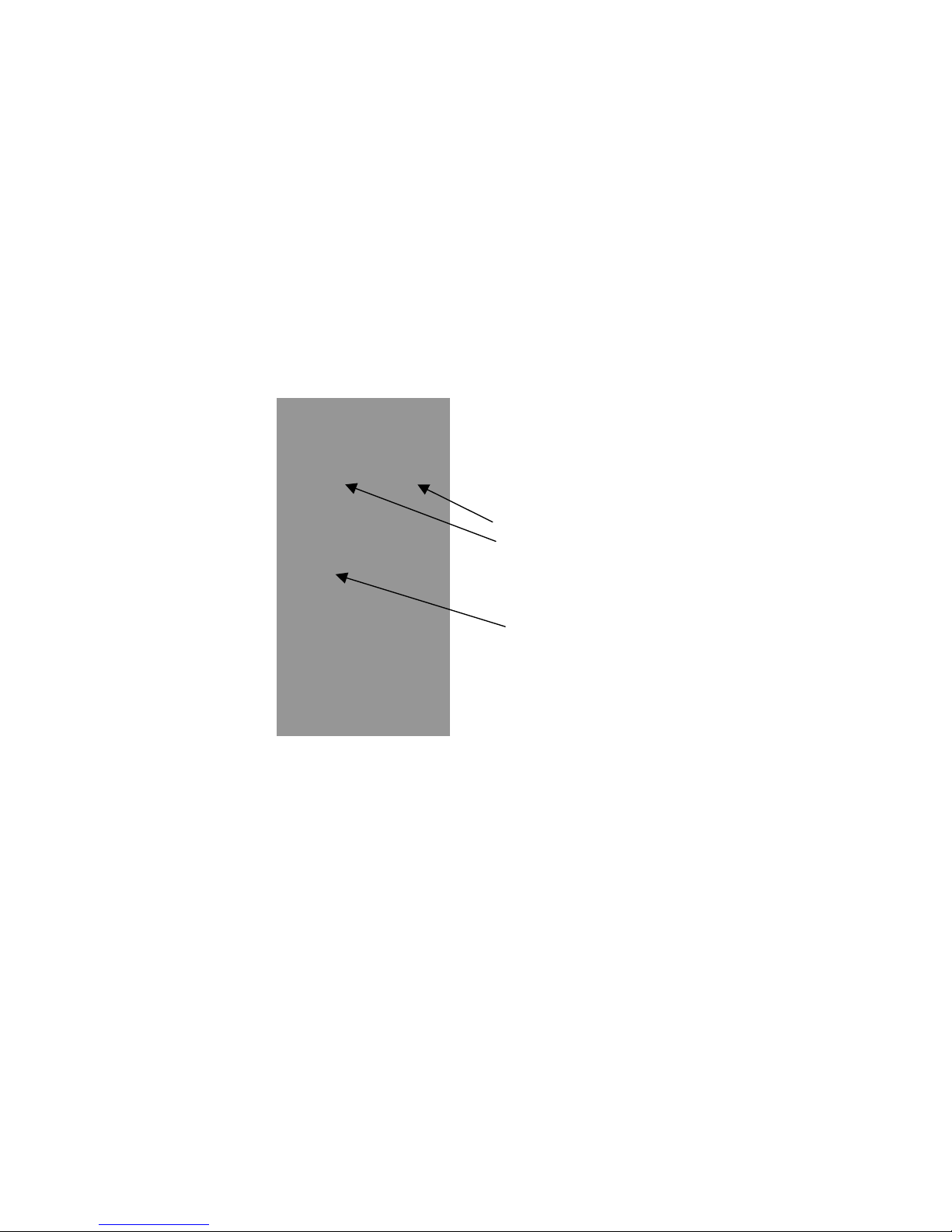
77
13.5 Frequency Scan Page
The Frequency Scan page automatically sweeps through a set tuning
range and plots the signal power at each frequency. It can also
automatically provide a list of decodable services within that range.
Starting a Scan
The front panel MODE button is used to start a scan whilst on the
Frequency Scan page. The MODE button can then be used to stop a
scan at any time. A scan consists of two stages which are described
belo
w.
During the scan any previous video link will stop working but will be
restored once the scan is completed or stopped.
Setting the Scan Range
The Scan Range and Resolution settings can be changed remotely
using RS232 control commands (see section 0), or by using the
Receiver Control Application (see section 8.3).
All settings default at 0 which means a range will be picked 100MHz
either side of the current frequency at 0.25
MHz resolution.
It’s recommend that you set the scan range (maximum and minimum
values) to the range in which your transmitters usually operate.
Maximum and minimum values will be automatically limited based on
the receiver’s ability with its current settings. Total scan range is limited
to 500MHz.
Resolution should be set based on your usual frequency settings. If your
transmitters are always set to mul
tiples a 1MHz then the resolution
should be set to 1MHz. A smaller resolution will result in a scan taking
longer to complete. Resolution defaults to 0.25MHz if set out of the
range 0.25MHz to 100MHz.
Frequency Scan
Minimum and maximum
signal level; this will
change during a scan as
the plot is automatically
scaled.
Frequency scale in GHz
shows the scan range
once a scan has started.
Page 78

78
Quick Scanning Stage
The quick scanning stage skips though the frequency range at intervals
depending on the resolution, and measures the signal level at each
interval. The signal level is taken as the maximum level at all available
antenna inputs and is plotted on the on screen display.
A chequered bar will move along the frequency axis representing the
current progress.
This stage is necessary for the service scanning st
age, however if the
users’ aim is to check for noise free frequencies to put their service on,
then the scan could be stopped at whatever point by pressing the
MODE button.
Service Scanning Stage
The service scanning stage jumps between the strongest signal levels
detected and checks for a decodable service.
If a service is found, signals around it will be ignored to save scanning
time as they are mostly likely part of the se
rvice. The number of
surrounding signals ignored depends on the bandwidth of the service
found.
Once a scan is finished, services found will be marked by a chequered
bar and stored. If a scan is stopped early the services found so far will
be marked and stored.
Note: If the receiver is in Narrowband mode only Narrowband services will be detected as
decodable. If the receiver is in DVB-T mode only DVB-T services will be detected.
Frequency Scan
Number of services
found so far.
Current scanning
frequency marked by
chequered bar.
Activity indicator.
Noise free area.
Page 79
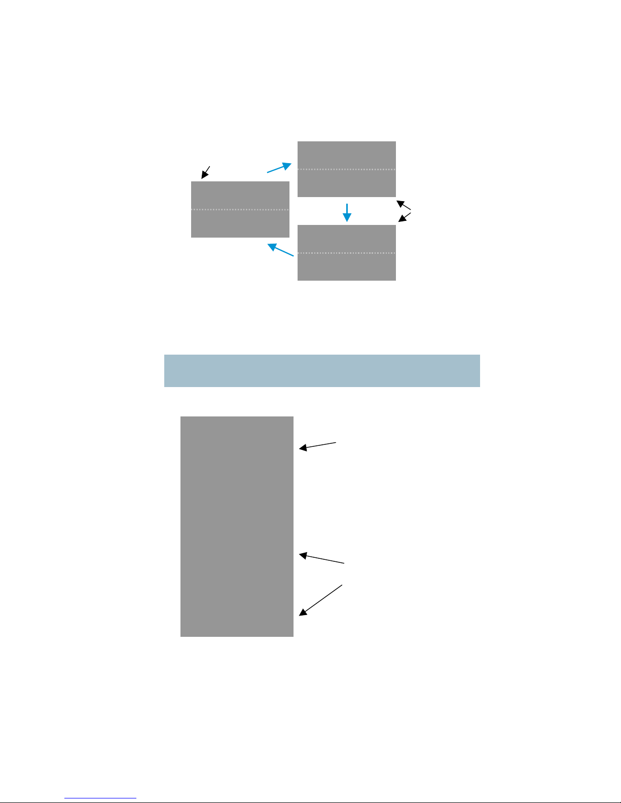
79
Completed Scan
Once a scan has been completed and one or more services have been
found, the CONFIG button can be used the cycle though available
services on screen, or to the re-scan message.
If a 'change’ message is displayed then pressing the MODE button will
result in changing current frequency and bandwidth settings to receive
that service.
Note: Changing the frequency and bandwidth settings in this way will overwrite the current
configuration settings.
Frequency Scan
Two alternating
messages
Example
where 2
services have
been found,
when currently
using
configuration 2.
Press MODE to
MODE to change
MODE to change
Services which have
been found at
1.395GHz and
1.500GHz are
marked by a
chequered bar.
‘Change to’ message giving
the option of jumping to a
service found at 1.395GHz.
This alternates with a warning
about which configuration you
will change.
Page 80

80
13.6 On Screen Display Control
Front Panel Control
The RF button on a receiver front panel can be used to cycle through
the OSD pages in the order shown below. Optional C and D input pages
will only be shown if antenna inputs C and D are available. Optional
GPS Overlay page will only show if Data is enabled.
Page Order
Receiver Input RF Advanced Engineering Data
(A and B) (A and B)
GPS Overlay Frequency Scan Engineering Data
(C and D)
Exceptions
When a rec
eiver is in Chaining Input mode the only page available will
be a partial version of the Receiver Input page. This will be renamed as
Chaining Input and only contain the encryption status. Cycling pages will
just turn the OSD on or off.
If the receiver is set to original OSD mode then pages will work as with
the original OSD (see section 0)
RF Advanced
----------Input(GHz) 2.50000
TPS Lock Yes
FEC Lock Yes
Constel QPSK
FEC Rate 1/3
G.Interval 1/16
AutoBW 1.25MHz
A: Input Lev. -74
SNR 21.5
Demod Lock Yes
B: Input Lev. -130
SNR - Demod Lock No
Pre LDPC Err 5314
Frequency Scan
------------- MODE to change
to 1.39500GHz?
-99 -46 P
1.25------------- |#
|##
1.30-########
|##
|#
1.35 |
x#########xxxx
1.40 |#
|#
1.45 |####
|
14:06:59 24/07/09
50 52.136 N 3D
Engineering Data
---------------C -65 SNR:25
|
| WWWWWWWW
| W W
|WWW WWW
----------------
D -130 SNR:
|
|WWWWWWWWWWWWWWWW
|
|
----------------
Transmitter:
GPS 14:06:59
3D 50 52.136 N
Fix 1 15.205 W
Input Status
-----------Frequency & Mode:
2.50000 GHz
Ultra Long Range
Encryption:
CLEAR
Antenna Input A:
Signal .ooooOO
Quality Excellent
Antenna Input B:
Signal .
Engineering Data
---------------A -65 SNR:25
|
| WWWWWWWW
| W W
|WWW WWW
----------------
B -130 SNR:
|
|WWWWWWWWWWWWWWWW
|
|
----------------
Transmitter:
GPS 14:06:59
3D 50 52.136 N
Fix 1 15.205 W
OSD
Off
Optional path
Page 81
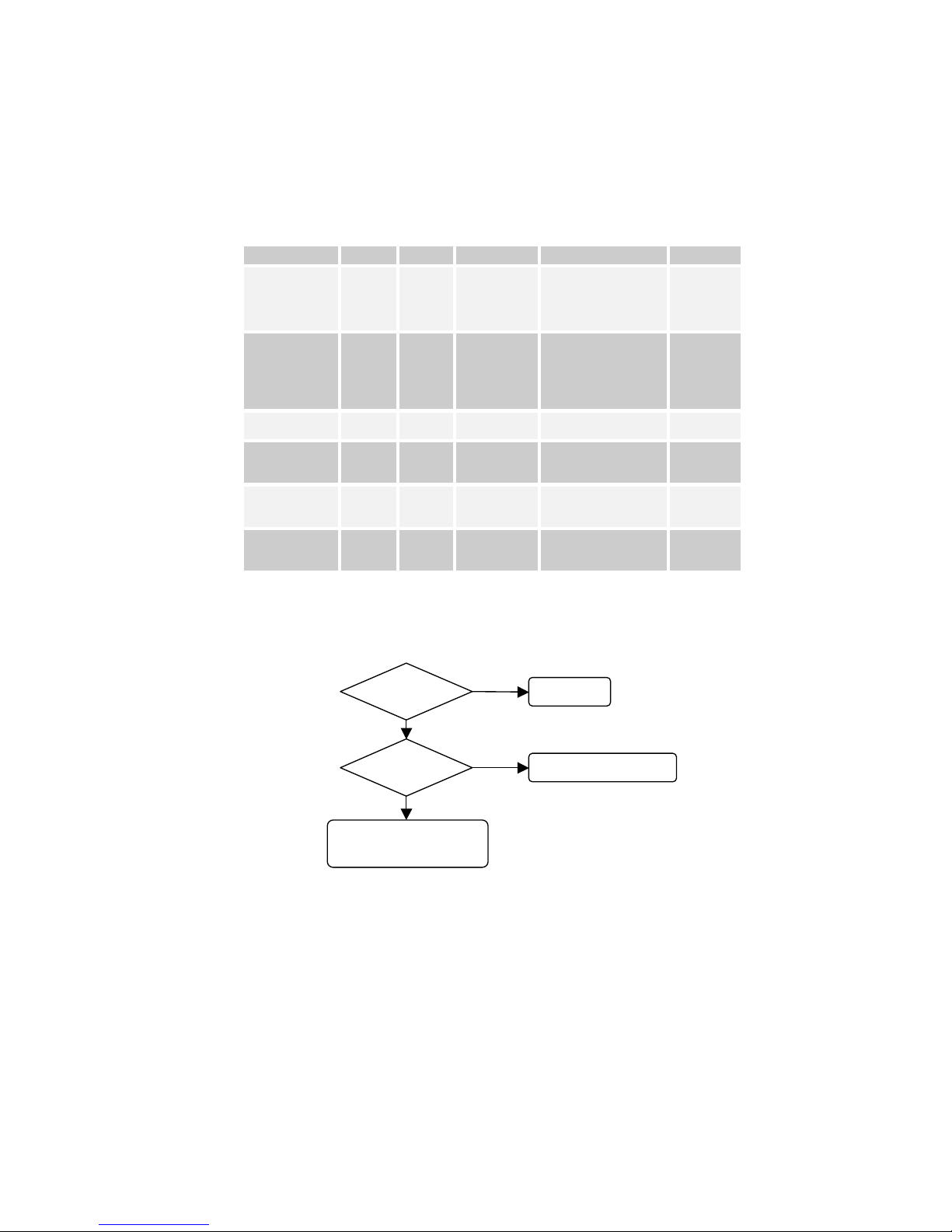
81
Control Commands
The OSD page can be changed remotely using RS232 control
commands, or by using the Receiver Control Application (see section
8.3). Relevant commands are shown below; please refer to the section
15 for how to use control commands.
Relevant Command List
Function
R/W
Block
Command
Data
Type
On Screen
Display
r/wgosd
0 = Off
1 = Channel A
2 = Channel B
3 = Channel C
4 = Channel D
List
On Screen
Display Page
r/wgosp
0 = Original
1 = Input Status
2 = RF Advanced
3 = Engineering Data
4 = Frequency Scan
5 = GPS Overlay
List
On Screen
Display Timeout
r/wgost
OSD timeout in
seconds
Integer
Frequency
Scan Range
Minimum
r/wgsmi
Starting frequency for
scan in GHz
Double
Frequency
Scan Range
Maximum
r/wgsma
Ending frequency for
scan in GHz
Double
Frequency
Scan
Resolution
r/wgsre
Resolution of
frequency scan in MHz
Double
The page displayed depends on a combination of the On Screen
Display (osd) value and the On Screen Display Page (osp) value.
If showing the Original OSD page the spectrum plot will correspond to
the On Screen Display (osd) value.
If showing the new Engineering Data page, the spectrum plots will
correspond to:
A and B if On Screen Display (osd) value = 1 or 2
C and D if On Screen Display (osd) value = 3 o
r 4
C and D will only be displayed if available.
osd = 0?
No OSD
osp = 0?
Show original OSD
Show corresponding
new OSD page
Yes
YesNoNo
Page 82

82
Original OSD Mode
Original OSD mode will be enabled if the On Screen Display Page (osp)
value is set to 0 (see above).
The RF button on a receiver front panel can then be used to cycle
through the original OSD pages in the order shown below. Optional C
and D input pages will only be shown if antenna inputs C and D are
available.
The pages can also be navigated remotely by setting the On Screen
Display (osd) value (see ab
ove).
Page Order
Original Page (A) Original Page (B) Original Page (C)
optional
Original Page (D)
optional
Input(GHz) 2.50000
Input Lev A -74
Input Lev B -130
Input Lev C -Input Lev D -Demod Lock A--TPS Lock OK
FEC Lock OK
Constel QPSK
Mod 1.25MHz 1/3
Pre LDPC Err 5314
Post LDPC Err 0
Packet Err 0
SNR A 22.1
SNR B -SNR C -SNR D -D
| WWWWWWWW
Input(GHz) 2.50000
Input Lev A -74
Input Lev B -130
Input Lev C -Input Lev D -Demod Lock A--TPS Lock OK
FEC Lock OK
Constel QPSK
Mod 1.25MHz 1/3
Pre LDPC Err 5314
Post LDPC Err 0
Packet Err 0
SNR A 22.1
SNR B -SNR C -SNR D -C
| WWWWWWWW
Input(GHz) 2.50000
Input Lev A -74
Input Lev B -130
Input Lev C -Input Lev D -Demod Lock A--TPS Lock OK
FEC Lock OK
Constel QPSK
Mod 1.25MHz 1/3
Pre LDPC Err 5314
Post LDPC Err 0
Packet Err 0
SNR A 22.1
SNR B -SNR C -SNR D -B
| WWWWWWWW
Input(GHz) 2.50000
Input Lev A -74
Input Lev B -130
Input Lev C -Input Lev D -Demod Lock A--TPS Lock OK
FEC Lock OK
Constel QPSK
Mod 1.25MHz 1/3
Pre LDPC Err 5314
Post LDPC Err 0
Packet Err 0
SNR A 22.1
SNR B -SNR C -SNR D -A
| WWWWWWWW
OSD
Off
Page 83

83
OSD Timeout
A timeout has been implemented such that if a timeout value is set and
there is no defined activity, then the OSD will automatically turn off after
the set period of time.
The timeout value can be set by using the On Screen Display Timeout
(ost) command (see section 0).
If the timeout is set to 0 (which it is by default) then the OSD timeout is
disabled.
Defined Activity
Certain activity will reset the O
SD timeout counter:
• Pressing the MODE / RF / CONFIG front panel buttons.
• If the OSD page is changed by any method.
• When a frequency scan finishes.
• If the device is reset.
The timeout is not active whilst a frequency scan is running.
Page 84

84
14 Connector Pin Outs
14.1 Power - 4-pin 0B LEMO Socket (TX and RX)
Pin No
Function
1
12 V
2
12 V
3
GND
4
GND
14.2 Control Data and Expansion - 16-pin Hirose 3500 series
connector & 0.1” OEM header (TX Only)
Pin No
Function
1
VBATT – only 1A on this pin
2
GND
3
RS232 TX1 (Control)
4
RS232 RX1
5
RS232 TX2 (Data)
6
RS232 RX2
7
GPIO to Atmel – can be used to wake up unit
8
Chaining Clock in or GPIO
9
GND
10
Chaining Data in or GPIO
11
Chaining Clock out or GPIO
12
GND
13
Chaining Data out or GPIO
14
GND
15
Luma/Composite in
16
Chroma in
14.3 Control Data and Expansion - 16-pin Hirose 3500 series
connector & 0.1” OEM header (RX Only)
Pin No
Function
1
Power
2
GND
3
RS232 TX1 (Control)
4
RS232 RX1
5
RS232 TX2 (Data)
6
RS232 RX2
7
GPIO
8
Chaining Clock in or GPIO
9
GND
10
Chaining Data in or GPIO
11
Chaining Clock out or GPIO
Page 85

85
12
GND
13
Chaining Data out or GPIO
14
GND
15
S-video Luma out
16
S-video Chroma out
14.4 Combined A/V - 5-pin 0B LEMO socket (TX Only)
Pin No
Function
1
Audio Right In
2
Audio Left In
3
GND
4
Composite In
5
GND
14.5 Audio - 5-pin 0B LEMO socket (Solo4RX)
Pin No
Function
1
N/C
2
N/C
3
GND
4
Audio Out + (Rx only)
5
Audio Out -
14.6 Audio - 3-pin 1B LEMO Socket (old style RX Only)
Pin No
Function
1
Right
2
Left
3
GND
14.7 RS232 Control - 3-pin 0B LEMO Socket (old style RX Only)
Pin No
Function
1
TX
2
RX
3
GND
Page 86

86
15 Control Protocols
The following section describes the control protocol employed on the
RS232 link for controlling the SOLO transmitters and receiver
equipment.
Connection details are detailed in previous sections.
Note that only features that are licensed for use in the SOLO units can be controlled. The
protocols listed here cover all possible features. Attempting to activate an unlicensed
feature will simply result in the command being ignored by the SOLO unit.
15.1 RS232 Control – General Principles
The physical interface is RS232 but this can be converted to RS 485
with an external adapter where multiple units are controlled over one RS
485 bus.
Normal operation involves sending a packet from the control device
(normally a PC) to the device being controlled. If the packet satisfies an
address integrity check, then the controlled device will action the
command and send a reply.
For compatibility
with modems an ASCII style protocol is used.
Ports are set for 8 bits, No parity, 1 stop
15.2 Packet Structure Sending (from PC)
ASCII Value
STX 02h Start byte
0-9 30h-39h 4 byte unit address. In range 0-9999
R 20h-7Eh 1 byte command type. r read, w write or
m misc
I 20h-7E 1 byte indicator of internal data block
ABC 20h-7Eh Command –three byte mnemonic
; 3Bh Separator
PQR 20h-7Eh Data –Optional, variable length
; 3Bh Separator
X 20h-7Eh Sum Check
ETX 03h End byte
Page 87

87
15.3 Packet Structure Reply (from controlled device)
ASCII Value
STX 02h Start byte
0-9 30h-39h 4 byte unit address. In range 0-9999
Z 20h-7Eh Status BYTE
PQR 20h-7Eh Data –Optional, variable length
; 3Bh Separator
X 20h-7Eh Sum Check
ETX 03h End byte
The Sum check byte is the summation of all bytes in the packet, not
including the start and end bytes. Higher order bytes are ignored and
the final byte result is modified to prevent ASCII control characters being
sent. Bit 7 (highest) is forced high.
Status byte will indicate command performed OK, or indicate an error.
ASCII Meaning
1 All OK
E General error, Command could not be actioned
Typically E will be returned if the message is formatted incorrectly
(separators in wrong place) or if commands are in upper case, or if
commands do not match against the allowed list of commands, or if the
checksum is wrong.
Addresses in the range 0001 to 9998 are for general use. Address 0000
is reserved and 9999 is a broadcast address. i.e. any device will reply to
this address. Its reply will contain its own specific address.
All data in the transmitter and receiver is stored as one of 5 data types,
Double, String, List, Integer or HexInteger. The data type dictates the
contents of the data section of the reply.
• List – 1 byte for sending. Value is hexadecimal coded as ASCII. 2 byte
reply. Reply represents index into original choice list. e.g. Reply 02
indicates entry 2 in original list.
• Double - variable length. Reply always contains decimal point and 4
decimal places. Can have 1 to 3 digits before decimal.
• Integer - 6byte reply. integer value with stuffed with preceding zeros.
e.g. GOP reply 000012 = GOP length 12
• String - Variable length. Reply is string excluding null terminator
• HexInteger – 8byte Hex reply
Page 88
88
15.4 Transmitter Command List
Type ‘o’ messages for Modulation commands
Function
R/W
Block
Command
Data
Type
Set
Modulation
IF output
r/woout
1 byte
0 OFF
1 COFDM
int
Set Narrow
Band
Modulation
FEC
r/wofec
1 byte
1 = 2/3
2 = 1/3
int
Set Narrow
Band
Modulation
Guard
Interval
r/wogua
1 byte
1 = 1/16
2 = 1/8
int
Set Narrow
Band
COFDM
mode
r/womod
1 byte
0 = QPSK
1 = 16 QAM
int
Set
Modulation
Freq
r/wofre
Set Frequency in
MHz, decimal point
allowed.
double
Spectrum
Inversion
r/wospe
1 byte
0 = Normal
1 = Inverted
int
COFDM
Bandwidth
r/wowid
0 = 6MHz
1 = 7MHz
2 = 8MHz
3 = 2.5MHz
4 = 1.25MHz
list
Output level
attenuation
high
r/wolev
Default level is 0
Value 0 to 32 1dB
steps
int
Output High
Low switch
r/wohls
0 = low level
1 = high level
(default)
int
Output level
attenuation
low
r/wollv
Default level is 32
Value 0 to 32
0.25dB steps
int
DVB-T FEC
r/wodfe
0 = 1/2, 1 = 2/3, 2 =
3/4, 3 = 5/6, 4 = 7/8
int
DVB-T
Guard
r/wodgu
0 = 1/32, 1 = 1/16, 2
= 1/8, 3 = 1/4
int
DVB-T mode
r/wodmo
0 = QPSK, 1 =
16QAM, 2 =
64QAM
int
DVB-T 4K
Offset
r/wo4ko
0 = none
1 = +4KHz
2 = -4KHz
Int
Range Mode
Preset
r/wotxm
0 = none
selected(default)
1 = short range
2 = medium range
3 = long range
4 = ultra long range
int
Type ‘z’ messages for Scrambling commands
Function
R/W
Block
Command
Data
Type
Scrambling
r/wzscr
1 byte
0 = Off
1 = ABS
4 = AES128
6 = AES256
int
AES Key
lower 128
wzkez
Encryption key for
AES lower 128
Hex string
(32
characters)
Page 89

89
AES Key
upper 128
used in AES
256 only
wzkex
Encryption key for
AES upper 128
Hex string
(32
characters)
ABS key
wzkey
Encryption key for
ABS
Hex string
(12
characters)
Type ‘v’ and ‘e’ messages for Video commands
Function
R/W
Block
Command
Data
Type
Video Input
r/wvinp
1 byte
0 = Off
2 = PAL
3 = NTSC
4 = NTSC No
Pedestal
5 = PAL S-vid
6 = NTSC S-vid
7 = NTSC S-Vid No
pedestal
8 = SDI PAL
9 = SDI NTSC
int
Video
Locked
rvloc
1 byte
0 = No
1 = Yes
int
Video Bitrate
(Only
applicable
when chain
in enabled)
r/wevid
Value in Mbps
double
Video
Horizontal
resolution
r/wehor
1 byte
0=704
1=528
2=480
3=352
int
Sleep if no
video lock
r/wvsle
0 = normal
1 = sleep if no video
int
MPEG mode
r/weenc
0 = MPEG2
1 = MPEG4
int
MPEG2
GOP length
S/W V3.6+
r/wegop
0 = stripe refresh
mode (default)
1 = intra only
2-100 = GOP
length in frames
int
MPEG4
frame rate
r/wefrm
0 = full
1 = 1/2
2 = 1/4
3 = 1/8
4 = 1/24
int
MPEG4
encoding
option
r/wecmd
0 = low delay
interlaced (default)
1 = standard delay
interlaced
2 = low delay
progressive
3 = standard delay
progressive
MPEG4
video
sharpness
r/wesha
0 = normal (default)
1 = sharp
int
Manual
Video Bitrate
r/wevbr
Video bitrate
manual over ride
0 = no override
(default)
Non-zero (sets the
video bit-rate in
kbps)
int
Video PID
r/wvpid
16-8190, 0
dissables
int
Page 90

90
Available
bitrate for
Video
reabr
Available bitrate in
transport stream for
video in Mbps
float
Type ‘a’ messages for Audio commands
Function
R/W
Block
Command
Data
Type
Audio
Encoder
Options
9,10,11 &12
are only
supported in
S/W V3.3+
Options
13,14,15
&16 are only
supported in
S/W V3.6+
r/waenc
1 byte
0 = Off
1 = 32kHz,12cbit,S
2 = 32kHz,12cbit,M
3 = 32kHz,8cbit,S
4 = 32kHz,8cbit,M
5 = 16kHz,8cbit,S
6 = 16kHz,8cbit,M
7 = 8kHz,8cbit,S
8 = 8kHz,8cbit,M
9 = 32kHz MPEG
Layer1 stereo
10 = 32kHz MPEG
Layer1 mono
11 = 48kHz MPEG
Layer1 stereo
12 = 48kHz MPEG
Layer1 mono
13 = 32kHz MPEG
Layer2 stereo
14 = 32kHz MPEG
Layer2 mono
15 = 48kHz MPEG
Layer2 stereo
16 = 48kHz MPEG
Layer2 mono
int
Audio Input
Level
r/walev
1byte
0 = 0dB (line level)
1= 12dB (mic level)
2 = 24dB(mic level)
3 = 36dB(mic level)
4 = 48dB(mic level)
and 4 also enables
ALC
int
MPEG
Layer 1
Audio Bitrate
S/W V3.3+
1byte
2 = 64kbit
3 = 96kbit
4 = 128kbit
5 = 160kbit
6 = 192kbit
7 = 224kbit
8 = 256kbit
9 = 288kbit
10 = 320kbit
11 = 352kbit
12 = 384kbit
13 = 416kbit
14 = 448kbit
MPEG
Layer 2
Audio Bitrate
S/W V3.6+
r/wampr
2 = 48kbit
3 = 56kbit
4 = 64kbit
5 = 80kbit
6 = 96kbit
7 = 112kbit
8 = 128kbit
9 = 160kbit
10 = 192kbit
11 = 224kbit
12 = 256kbit
13 = 320kbit
14 = 384kbit
int
MPEG Audio
Offset
r/wapts
PTS offset for
MPEG Audio
int
Audio
Left/Right
Swap
S/W V3.6+
r/walrs
0 = normal stereo
1 = swapped stereo
int
Audio Mono
r/warmo
0 = left mono
Int
Page 91

91
Select
S/W V3.6+
1 = right mono
Audio PID
r/wapid
16-8190, 0
dissables
int
Type ‘g’ and ‘p’ messages for Unit Level commands
Function
R/W
Block
Command
Data
Type
Software
Version
rgver
Software version
number
Hex string
FPGA
Version
rgfpg
Fpga version
number
Hex string
Serial
Number
rgser
Hex based serial
number
Hex string
License
Code
wglic
License number for
software facilities
Hex string
Narrow band
Service
Name
r/wgnam
Unit Name String
string
Set Unit
address
r/wgadd
Unit Address
0001 - 9998
int
Load
Configuration
Number
r/wglod
Config Number
int
Restore
Default Build
wgdef
1 byte
0 = No
1 = Yes
int
Sleep Mode
r/wgsle
1 byte
0 =No
1 = Yes
int
Front Panel
Lock
r/wgfpl
0 = unlocked
1 = locked
int
DVB-T
Service
name
r/wgdna
Unit Name String
string
Heart beat
enable
r/wgblo
0 = off
1 = on
int
Initiate Code
download
S/W V3.3+
wgdlc
65 to initiate full
download
67 to initiate code
only download
int
PCR PID
r/wpcpd
16-8190, 0
dissables
int
PMT PID
r/wpmpd
16-8190, 0
dissables
int
Board Type
rgbty
Returns ‘D510’ for
D510
string
Unit Type
r/wguty
Unit type as set
using the ‘u’
command on
power-up
int
License
Mask
rglma
Bit mask of licensed
features
Hex String
NOTE: inappropriate use of the ‘gdlc’ command will render the unit unusable
Type ‘d’ and ‘m’ messages for Data commands
Function
R/W
Block
Command
Data
Type
Data On/Off
r/wdinp
1 byte
0 = Off
- 8 bit data 1 = no parity
2 = even parity
3 = odd parity
- 7 bit data -
int
Page 92

92
5 = no parity
6 = even parity
7 = odd parity
Input Data
Baudrate
r/wdbau
1 byte
0 = 1200 baud
1 = 2400 baud
2 = 4800 baud
3 = 9600 baud
4 = 19200 baud
5 = 38400 baud
6 = 57600 baud
(note 57600 is not
supported in DVB-T
modes)
7 = 115200 baud
int
Data PID
r/wdpid
16-8190, 0
dissables
Int
Metadata
Enable
S/W V3.6+
r/wmeta
1 byte
0 = Off
1 = On
int
Metasata
PID
r/wmpid
16-8190, 0
dissables
int
Page 93

93
Type ‘c’ messages for Chaining commands
Function
R/W
Block
Command
Data
Type
Chaining
Input
r/wcinp
1 byte
0 = Off
1 = On
2 = Relay
int
Chaining
Output
r/wcout
1 byte
0 = Off
1 = On
int
Chaining
Loop
r/wchio
1 byte
0 = Off
1 = output loop to
input for external
encryption
int
Chaining
status
–describes if
chaining
input is
active
rcsta
1 byte
0 = Not Active
1 = Active
2 = Overflow
int
Chain
Number
r/wccha
0 - 9
int
Lowest
Operating
Frequency
r/wcflo
Frequency in MHz
double
Highest
Operating
Frequency
r/wcfhi
Frequency in MHz
double
Intermediate
Operating
Frequency 1
r/wcfl1
Frequency in MHz
double
Intermediate
Operating
Frequency 2
r/wcfl2
Frequency in MHz
double
Calibration
point lowest
r/wcpl1
0 – 32 in 0.25dB
steps
int
Calibration
point
intermediate
1
r/wcpl2
0 – 32 in 0.25dB
steps
int
Calibration
point
intermediate
2
r/wcpl3
0 – 32 in 0.25dB
steps
int
Calibration
point highest
r/wcpl4
0 – 32 in 0.25dB
steps
int
IQ Trim
mode
S/W V3.3+
r/wcitr
0- normal operation
1 – Set single/lower
2 - set mid point
3 – set upper point
int
I trim Value
S/W V3.3+
r/wciqi
-128 to +127
Signed but set and
read as unsigned
(255 = -1)
int
Q Trim Value
S/W V3.3+
r/wciqq
-128 to +127
Signed but set and
read as unsigned
int
Page 94

94
15.5 Receiver Command List
Type ‘1’ messages for Tuner / Demod
Description
Type
Block
Command
Data Sent
Data
Type
Input
Frequency
r/w1ipf
This is the
frequency
received by the
antenna.
Decimal point
allowed.
Double
Down
Converter LO
r/w1dco
Decimal point
allowed.
Double
Down
Converter LO
Side
r/w1los
0=low
1=high
List
OFDM
Bandwidth
r/w1wid
N.Band Mode
3 = 2.5MHz
4 = 1.25MHz
DVBT Mode
0 = 8MHz
1 = 7MHz
2 = 6MHz
List
OFDM
Modulation
Mode
r1mod
N.Band Mode
0 = QPSK
1 = 16QAM
DVBT Mode
0 = QPSK
1 = 16QAM
2 = 64QAM
List
OFDM FEC
r1fec
N.Band Mode
1 = 2/3
2 = 1/3
DVBT Mode
0 = 1/2
1 = 2/3
2 = 3/4
3 = 5/6
4 = 7/8
List
OFDM
Guard
N.Band
Mode
r/w
DVBT
Mode
r
1
gua
N.Band Mode
1 = 1/16
2 = 1/8
DVBT Mode
0 = 1/32
1 = 1/16
2 = 1/8
3 = 1/4
List
OFDM
Pol
r1pol
0 = Normal
1 = Inverted
List
Input SNR A
r1snr
Input SNR in dB
Double
Input SNR B
r1mer
Input SNR in dB
Double
Input SNR C
r1cer
Input SNR in dB
Double
Input SNR D
r1dnr
Input SNR in dB
Double
BER Pre
Viterbi
r1pre
Pre Viterbi x 10-6
Int
BER Post
Viterbi
r1pos
Post Viterbi x 10-6
Int
Packet errors
r1pkt
Int
Lock Status
r1loc
0 = Not Locked
1 = Locked
List
Input Level A
r1ina
Input Level in dBm
Double
Input Level B
r1inb
Input Level in dBm
Double
Input Level C
r1Inc
Input Level in dBm
Double
Input Level D
r1ind
Input Level in dBm
Double
Page 95
95
Type ‘g’ messages for Unit level commands
Description
Type
Block
Command
Data Sent
Data
Type
Unit Mode
r/wgudm
0 = Narrow
Band
1 = DVBT
List
Input Mode
r/wgmod
0 = RF Input
8 = Chaining
Input
List
LNB Power
r/wglnb
0 = OFF
1 = ON
List
Unit RS232
Address
r/wgadd
Unit Address
0001 - 9998
Integer
Software Version
rgsof
Software
Version
Number
String
FPGA Version
rgfpg
FPGA Version
Number
String
Serial Number
rgser
Hex based
Serial Number
String
License Code
wglco
License
number to
enable certain
features
List
On Screen
Display
r/wgosd
0 = Off
1 = Channel A
2 = Channel B
3 = Channel C
4 = Channel D
List
On Screen
Display Page
S/W V3.6+
r/wgosp
0 = Original
1 = Status
2 = Advanced
3 = Eng. Data
4 = Scanning
5 = GPS
List
On Screen
Display Timeout
S/W V3.6+
r/wgost
OSD timeout
in seconds
Integer
Frequency Scan
Range Minimum
S/W V3.6+
r/wgsmi
Starting
frequency for
scan in GHz
Double
Frequency Scan
Range Maximum
S/W V3.6+
r/wgsma
Ending
frequency for
scan in GHz
Double
Frequency Scan
Resolution
S/W V3.6+
r/wgsre
Resolution of
frequency
scan in MHz
Double
Auxiliary Address
(used in daisy
chaining mode)
r/wgaux
Unit Address
0001 - 9998
Integer
AGC Meter
Scale
r/wgagc
Range 0 - 10.0
Decimal point
allowed.
Double
Daisy Chain
RS232 Control
r/wgcdc
0 = OFF
1 = ON
List
Auto Spectrum
Detection
(Narrow Band)
r/wgasd
0 = OFF
1 = ON
List
Chaining Output
Mode 1
r/wgcha
0 = Demod
1 = Chaning In
List
Chaining Output
Mode 2
r/wgch2
0 = PreDescrambling
1 = PostDescrambling
List
License Mask
rglma
Bit mask of
licensed
features
Integer
Page 96

96
Down Converter
Gain Offset
r/wgdcg
Range -30.0 +30.0.
Decimal point
allowed.
Double
Board Type
rgbty
PCB Type
String
Type ‘e’ messages for Decoder configuration commands
Description
Type
Block
Command
Data Sent
Data
Type
Unit Number
r/weser
Index into List of
programs
List
Preferred Unit
Name
r/wedef
Preferred Unit
Name
String
525 Video Format
r/we525
1 = NTSC
2 = NTSC No
Ped
List
Locked
reloc
0 = No
1 = Yes
List
Line Standard
relin
0 = 625
1 = 525
Integer
Fail mode
r/wefai
0 = freeze
1 = blue
List
Power Up Line
Standard
r/wepwr
0 = 625
1 = 525
List
Service
Scrambling
Status
rescr
0 = Clear
1 =Scrambled
List
MPEG-4 Deblocking Filter
r/wedeb
0 = Enable
1 = Disable
List
Received Video
Type
revid
0 = MPEG-2
1 = MPEG-4
List
Transmitter Video
Input Lock
retxv
0 = Unlocked
1 = Locked
List
Default Service
Name Match
redsm
0 = No match
1 = Match
List
Video PID
revpi
13-bit PID
Integer
Audio PID
reapi
13-bit PID
Integer
Data PID
redpi
13-bit PID
Integer
Video Frame Lock
Mode
r/wefra
0 = Received sig.
1 = Local/Internal
List
Type ‘d’ messages for Memory configuration commands
Description
Type
Block
Command
Data Sent
Data Type
Store
Current
Configuration
to Memory
r/wdsto
Config
Address (1
to 9)
Integer
Load
Configuration
from Memory
into current
r/wdloa
Config
Address (1
to 9)
Integer
Restore
Default Build
r/wddef
0 = No
1 = Yes
List
Read
number of
last config
loaded
rdlas
Config
Address
Integer
Page 97

97
Type ‘z’ messages for Descrambling commands
Description
Type
Block
Command
Data Sent
Data
Type
Descrambling
r/wzdes
0 = Off
1 = ABS
4 = AES128
5 = AES128+
6 = AES256
7= AES256+
List
ABS
Scrambling
Key
wzebs
Alink basic
scrambling
key
8-digit
hex string
AES
Scrambling
Key – lower
128 bits
wzaes
Advanced
Encryption
Standard –
lower 128 bits
32-digit
hex
string
AES
Scrambling
Key – upper
128 bits used
in AES256
only
wza25
Advanced
Encryption
Standard –
upper 128 bits
32-digit
hex
string
Type ‘t’ messages for RS232 data pipe commands
Description
Type
Block
Command
Data Sent
Data
Type
Data On/Off
r/wtdat
0 = Off
1 = On
List
Data
Baudrate
rtbau
2 = 1200 baud
3 = 2400 baud
4 = 4800 baud
5 = 9600 baud
6 = 19200 baud
7 = 38400 baud
8 = 57600 baud
9 = 115200 baud
List
Data Parity
r/wtpar
0 = none
1 = even
2 = odd
List
Page 98
98
16 Default Configurations
This section tabulates the default configuration settings for domo SOLO
products.
Item
SOL2TX-228255 (2.28 to
2.55GHz)
SOL2TXLE-240248 (2.4
to 2.483GHz)
SOL4TX-228255 (2.28 to
2.55GHz)
SOL4TXLE-240248 (2.4
to 2.483GHz)
SOL2TX-115140 (1.15 to
1.4GHz)
SOL2TXLE-138139 (1.389
to 1.399GHz)
SOL4TX-115140 (1.15 to
1.4GHz)
SOL4TXLE-138139 (1.389
to 1.399GHz)
RF Output
OFF
OFF
Frequency
2405MHz
1395MHZ
Modulation
QPSK
QPSK
Power
Maximum
Maximum
Standby
OFF
OFF
Unit Address
0001
0001
Unit name
Solo-01 (SOLO4) Unit 1 (SOLO2)
Solo-01 (SOLO4) Unit 1 (SOLO2)
Horizontal
Resolution
528
528
Video Input
PAL
PAL
Audio
OFF
OFF
Data
OFF
OFF
Audio Input
Line level
Line level
Scrambling
OFF
OFF
AES Key
None
None
Item
SOLO2/SOLO4 RX
Configs 1 to 4
SOLO2/SOLO4 RX
Configs 5 to 8
LNB Power
ON
ON
Frequency
2405MHz
1395MHZ
Down converter LO
1880
1700
LO Side
Low
High
Unit Address
0001
0001
Default Service
Solo-01 (SOLO4) Unit 1 (SOLO2)
Solo-01 (SOLO4) Unit 1
(SOLO2)
Video Fail
Blue Field
Blue Field
Data
OFF
OFF
De-Scrambling
OFF
OFF
AES Key
None
None
Page 99

99
Cobham Surveillance
Domo Products
11 Manor Court, Barnes Wallis Road, Segensworth,
Hampshire, PO15 5TH, England
T: +44 (0)1489 566 750
F: +44 (0)1489 880 538
Current
selected
Config
RF Advanced
----------Input(GHz)
2.50000
TPS Lock
Yes
FEC Lock
Yes
Constel
 Loading...