

COBHAM SOLO2, SOLO4 User Manual

Page 1 Specifications subject to change without notice
, 18th October 2004
SOLO2 and SOLO4
Users’ Manual
Users’ Manual
Version 2.8
7 October 2009
Cobham Surveillance
Domo Products
11 Manor Court, Barnes Wallis Road, Segensworth,
Hampshire, PO15 5TH, England
T: +44 (0)1489 566 750
F: +44 (0)1489 880 538
2
1 Table of Contents
1 Table of Contents .................................................................................... 2
2 Change History........................................................................................4
3 About this Manual.................................................................................... 5
4 Introduction............................................................................................. 6
5 Warranty and Support..............................................................................7
5.1 Warranty Cover.........................................................................................7
6 Safety, Compliance and Approvals ...........................................................8
6.1 Safe Operating Procedures.........................................................................8
6.2 EMC / Safety and Radio Approvals ..............................................................8
6.3 CE marking ..............................................................................................8
7 Getting Started and Basic Operation.......................................................10
7.1 Which Model do I have? ........................................................................... 10
7.2 Getting Started with the Transmitter ...........................................................15
7.3 Getting Started with the SOLO Receiver ..................................................... 22
7.4 Powering on the System........................................................................... 31
7.5 Domo Batteries and Battery Charging.........................................................33
7.6 Using the Clip On 1W Amplifier ................................................................. 35
7.7 Using the booster 5W Amp ....................................................................... 37
8 Advanced Operation .............................................................................. 41
8.1 SOLO System PC Controller Application Software ....................................... 41
8.2 Transmitter Control Application..................................................................43
8.3 Receiver Control Application ..................................................................... 51
9 NETSTREAM IP Output Option ...............................................................59
9.1 General Info............................................................................................ 59
9.2 Streamer ................................................................................................59
9.3 Web Server ............................................................................................59
10 Software Decoder .................................................................................. 62
10.1 General Information .................................................................................62
10.2 Decoding Multicast Streams...................................................................... 63
10.3 Encrypted Streams .................................................................................. 65
10.4 Main Decoder Window ............................................................................. 67
10.5 Decoding Locally Stored Files ................................................................... 69
10.6 Miscellaneous application options .............................................................. 69
11 Fault Finding ......................................................................................... 71
11.1 Indicated Faults....................................................................................... 71
11.2 Fault Symptoms ...................................................................................... 72
12 LED Indicators....................................................................................... 73
13 Receiver On Screen Display ................................................................... 74
13.1 Input Status Page.................................................................................... 74
13.2 RF Advanced Page..................................................................................75
13.3 Engineering Data Page ............................................................................ 76
13.4 GPS Overlay........................................................................................... 76
13.5 Frequency Scan Page..............................................................................77
13.6 On Screen Display Control........................................................................ 80
14 Connector Pin Outs ...............................................................................84

3
14.1 Power - 4-pin 0B LEMO Socket (TX and RX)...............................................84
14.2 Control Data and Expansion - 16-pin Hirose 3500 series connector & 0.1”
OEM header (TX Only).........................................................................................84
14.3 Control Data and Expansion - 16-pin Hirose 3500 series connector & 0.1”
OEM header (RX Only) ........................................................................................84
14.4 Combined A/V - 5-pin 0B LEMO socket (TX Only)........................................ 85
14.5 Audio - 5-pin 0B LEMO socket (Solo4RX) ................................................... 85
14.6 Audio - 3-pin 1B LEMO Socket (old style RX Only)....................................... 85
14.7 RS232 Control - 3-pin 0B LEMO Socket (old style RX Only) ..........................85
15 Control Protocols .................................................................................. 86
15.1 RS232 Control – General Principles ...........................................................86
15.2 Packet Structure Sending (from PC)........................................................... 86
15.3 Packet Structure Reply (from controlled device)...........................................87
15.4 Transmitter Command List........................................................................ 88
15.5 Receiver Command List ........................................................................... 94
16 Default Configurations ........................................................................... 98

4
2 Change History
Version
Main Changes from Previous Version
Edited By
v1.0
Initial Release
MB
V1.1
Removed error stating that transmitter does not
support RS232 data
MB
V1.2
Warning added for static discharge on antennas
MB
V1.3
Additional information added:
Battery Charging
Clip on Amp
OSD analysis
Error in MPEG4 transmitter commands
corrected.
MB
DE
V1.4
Audio levels corrected
SOL4RX Added
MM
MB
V1.5
Updated chaining mode RS232 commands
MB
V1.6
Added new Solo4RX box Audio connector
details
NMcS
V1.7
Added new TX and RX controller sections for V2
controllers, added new TX system diagram,
updated Software Decoder
NMcS
V1.8
Updated receiver remote control commands list
MZ
V1.9
Added detail on Software decoder licensing
NMcS
V2.0
Added the User name and Password required to
Browse to the IP Streamer
NMcS
V2.1
Added MPEG audio and I Q trim commands
NMcS
V2.2
Added missing 1.25MHz entry in receiver
remote control commands list
MZ
V2.3
Added video frame lock mode in receiver
commands list. Removed 625-line format mode
(obsolete command)
MZ
V2.4
V2.3 converted to new Cobham template
AT
V2.5
Added new down-converter details
NMcS
V2.6
Added new OSD manual section and related
receiver remote commands
Fixed section numbering and TOC
RL
V2.7
Updated transmitter remote commands
RL
V2.8
Updated transmitter remote commands
TPM

5
3 About this Manual
This manual describes the operation of domo SOLO2 and SOLO4
digital wireless systems. The manual is divided into three main
sections.
• Getting started and basic operation
This section describes to users how to deploy and use a domo SOLO
system.
• Advanced operation
This section describes the operation of the system in more detail,
concentrating particularly on how to store and recall configurations, wit
h
use of the PC Controller Application.
• Technical reference
This section provides technical specification and control protocol data
and will be of interest to those integrating the SOLO system into larger
systems.

6
4 Introduction
The domo SOLO4 and SOLO2 product range enables the user to build
wireless digital microwave video systems. The domo SOLO4 and
SOLO2 products have been designed to provide rugged point-to-point
links for high quality full frame rate video, and audio, even in non line of
sight and urban environments.
Existing analogue systems suffer from impairments such as video noise,
loss of colour information and poo
r image quality when line of sight
cannot be maintained, and solutions based on wireless internet
standards and PC platforms deliver poor quality video.
The domo SOLO4 and SOLO2 system is a digital system that uses the
COFDM modulation technique, which effectively eliminates the
problems caused by multipath and reflections.
The SOLO product range allows law enforcement, surveillance and
emergency service
communities to now receive the highest quality
video images, in real time, direct from personnel, buildings and vehicles.
The domo SOLO2 system employs the DVB-T 2K carrier COFDM
technology.
The domo SOLO4 system employs a revolutionary narrow band
2.5MHz COFDM technology which demonstrates better propagation for
longer range links, and extra bandwidth efficiency. The domo SOLO4
system can also be upgr
aded to include a 1.25MHz COFDM modulation
and MPEG4 compression for excellent range performance.
The domo SOLO4 and SOLO2 systems employ common transmitter
and receiver hardware.
• The SOLO4 and SOLO2 transmitter is a lightweight, low-power
transmitter suitable for body-worn applications where size, weight and
power consumption are at a premium.
• For longer range applications such as vehicle transmissions, the
SOLO4 or SOLO2 transmitter can be upgraded with the use of a
booster amplifier.
• The SOLO4 and SOLO2 receivers are diversity input receivers with
extensive built in spectrum analysis tools. The receivers can be fitted
with an optional NETSTREAM card, which then gives the option of
streaming the received video onwards over IP networks.
IMPORTANT NOTE
The SOLO4 and SOLO2 product range has been specifically designed for government
security and law enforcement users, the equipment will tune across frequencies that are
only available to licensed government users. Non-government users should employ the
equipment restricted to the license exempt bands only typically 1.389 to 1.399GHz, 2.400
to 2.483GHz and 5.725 to 5.875GHz

7
5 Warranty and Support
5.1 Warranty Cover
domo offers a 12 month standard product warranty. During this period,
should the customer encounter a fault with the equipment we
recommend the following course of action:
• Check the support section of the website for information on that product
and any software/firmware upgrades. If fault persists;
• Call our support line and report the fault. If fault persists and you are
informed to return the
product please obtain an RMA number from the
domo support department, and ship the equipment with the RMA
number displayed and a description of the fault. Please email the
support section the airway bill/consignment number for tracking
purposes.
• If you have extended warranty provisions then domo will send an
immediate advance replacement to you. Under most circumstances
this must be returned once the
fault item is repaired.
Depending on the nature of the fault domo endeavor to repair the
equipment and return it to the customer within 14 days of the item
arriving at our workshops.
Obviously it is impossible to cater for all types of faults and to manage
100% replacement part availability, and delays are sometimes
inevitable. This is why domo recommend that its customers take out an
extended warranty
(which includes advanced replacement of faulty
items), and/or hold a basic level of spare parts, which can be held by
domo on the customer’s behalf.
Please contact domo for details of packages that can be tailored to meet
your individual needs, whether they are service availability, technical
training, local geographic support or dedicated spares holdings.

8
6 Safety, Compliance and Approvals
6.1 Safe Operating Procedures
• Ensure that the power supply arrangements are adequate to meet the
stated requirements of each SOLO4 or SOLO2 product.
• Operate within the environmental limits specified for the product.
• Do not subject the indoor equipment to splashing or dripping liquids.
• Only authorized, trained personnel should open the product. There are
no functions that required the User to gain access to the interior o
f the
product.
6.2 EMC / Safety and Radio Approvals
The equipment has been designed to meet and has been tested against
the following harmonized EMC and safety standards:
• EN 301 489-1 & EN 301 489-5
• EN 61000-3-2:2000
• EN 61000-3-3:1995
• EN 55022:1998, Class B
• EN 61000-4-2:1995
• EN 61000-4-3:1996
• EN 61000-4-4:1995
• EN 61000-4-5:1995
• EN 61000-4-6:1996
• EN 61000-4-11:1994
• EN 60950:2000
• The license exempt equipment (SOL2TX-138139, SOL2TX-240248,
SOL4TX-138139 and SOL4TX-240248) meets the following radio
approvals.
• EN 302 064-1
6.3 CE marking
The CE mark is affixed to all SOLO4 and SOLO2 products, and the CE
Declaration of Conformity, as well as the technical file are available on
request.

9
10
7 Getting Started and Basic Operation
7.1 Which Model do I have?
Each unit in the domo SOLO4 and SOLO2 product range is marked
with two panels.
• Product Code Panel. Give product code and manufacturers
information.
• CE and Serial Number Panel. Gives CE mark and product
serial number.
The domo product code can be referenced in the table below.
Product Code
Product
Accompanying items
SOL2TX-115140 (1.15 to 1.4GHz)
SOL2TX-228255 (2.28 to
2.55GHz)
SOL2TX-034047 (340 TO
470MHz)
SOL2TX-057067 (575 to 675MHz)
SOL2TX-310340 (3.1 to 3.4GHz)
SOL2TX-488515 (4.88 to 5.1GHz)
SOL2TX-560590 (5.6 to 5.9GHz)
SOL2TXLE-138139 (1.389 to
1.399GHz)
SOL2TXLE-240248 (2.4 to
2.483GHz)
100mW DVB-T
Digital Video
transmitter
Cables:
Video and audio 2m
Control 3m
DC Power 2m
SOL4TX-115140 (1.15 to 1.4GHz)
SOL4TX-228255 (2.28 to
2.55GHz)
SOL4TX-034047 (340 TO
470MHz)
SOL4TX-057067 (575 to 675MHz)
SOL4TX-310340 (3.1 to 3.4GHz)
SOL4TX-488515 (4.88 to 5.1GHz)
SOL4TX-560590 (5.6 to 5.9GHz)
100mW DVB-T
and Narrow
Band Digital
Video
transmitter
Cables:
Video and audio 2m
Control 3m
DC Power 2m
domo SOL4TX-228255
S-Band
Made in the UK

11
SOL4TXLE-138139 (1.389 to
1.399GHz)
SOL4TXLE-240248 (2.4 to
2.483GHz)
SOL2RX
SOLO2
Receiver
Additional Units:
Cables:
2 lengths of 3m low loss RF
cable
AC/DC power supply
Video 3m
Audio 3m
Control 3m
SOL4RX
SOLO4
Receiver
Additional Units:
Cables:
2 lengths of 3m low loss RF
cable
AC/DC power supply
Video 3m
Audio 3m
Control 3m
SOLAMP1W
1W Clip on
Amp
AMP 1W Clip On Video TX
SOL2 or SOL4 1.25 to 2.5Ghz
Note: SOLO2 / 4 Receivers are available in two box styles, referred to as Box Style 1 and
Box Style 2, through the remainder of the document.
Note: Receivers are made frequency specific by the addition of the appropriate downconverters.
DC-100140
L-band to UHF
down-converter
For use with SOLRX receiver
DC-225265
S-band to UHF
down-converter
For use with SOLRX receiver
DCB-450500
C-band to UHF
down-converter
For use with SOLRX receiver
DCB-550600
5.7GHz to UHF
down-converter
For use with SOLRX receiver
Note: DC-XXXXXX units are old style square down-converters. DCB-XXXXXX
are new style Barrel down-converters. See section

12
Controls
Transmitter Control Panels:
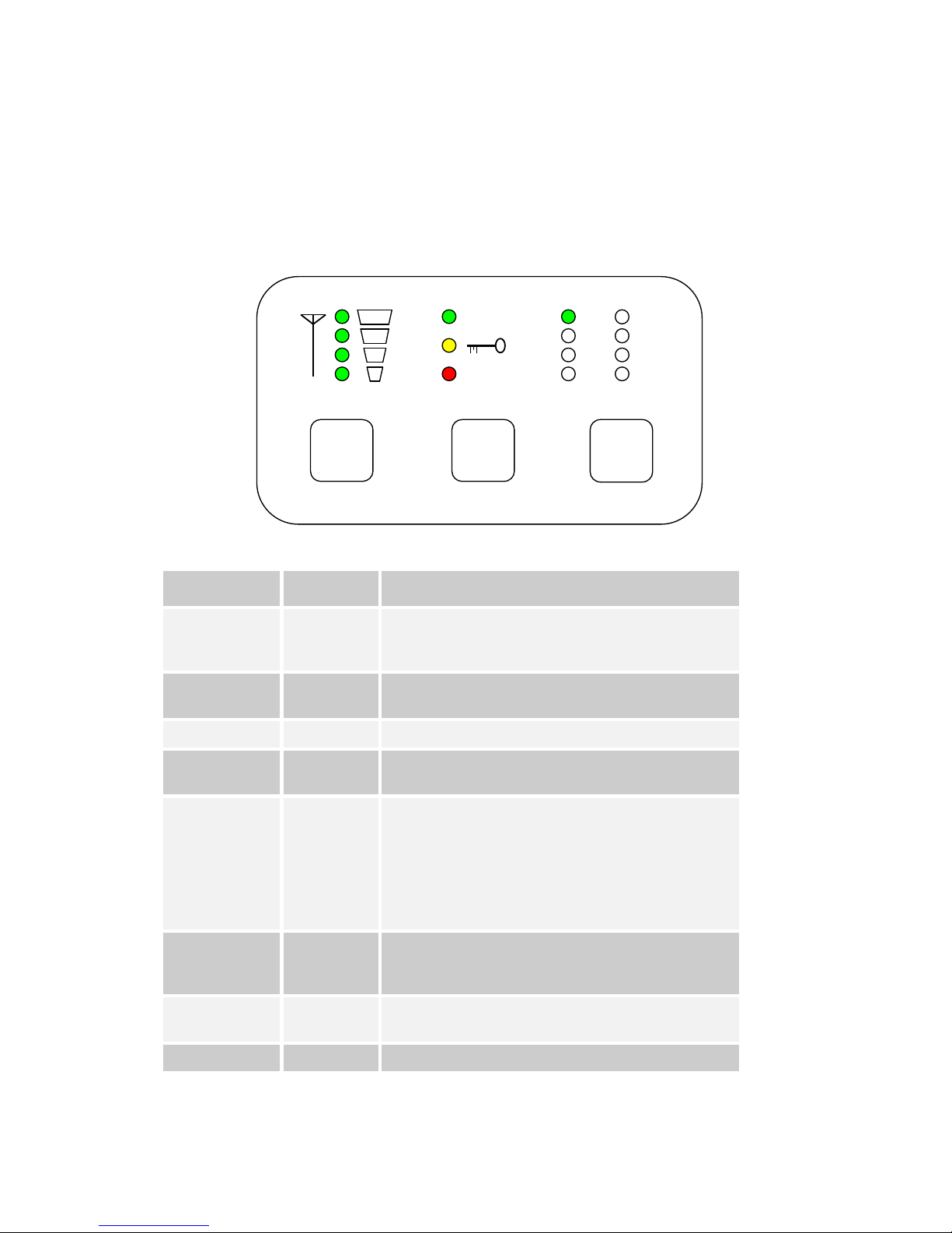
SOLO2 and SOLO4 transmitters are equipped with a standard LED
(Light Emitting Diode) and push button panel. The panel is as depicted
below, and the buttons and LEDs have meanings as explained in the
table.
LED / Button
Colour
Meaning / Use
Alarm LED
Red
When lit indicates alarm or fault condition on equipment. Usually
means no lock to incoming video.
Front Panel Lock
LED
Yellow
When lit indicates the stream is encrypted (v 3 software and above)
RF LED
Green
Transmitter: When lit indicates RF output is active.
LED 1 to 8
Green
Indicates which of the 8 stored configurations is currently selected.
Range Mode
LEDs
Green
SOLO2 Transmitter: These LEDs have no function
SOLO4 Transmitter: Indicates range mode
Ultra Long Range: 1.25MHz QPSK FEC1/3 (optional)
Long Range: 2.5MHz QPSK FEC1/3
Medium Range: 2.5MHz QPSK FEC2/3
Short Range: 2.5MHz 16QAM FEC2/3
RF Button
-
Transmitter:
Pressing the RF button toggles the units RF output between OFF
and ON.
Holding down button toggles unit into standby mode.
Config Button
-
The config button when pressed selects the next configuration from
memory.
Holding down button toggles front panel lock.
Mode Button
-
SOLO2 Transmitter – No function
SOLO4 Transmitter – Toggles between the range modes previously
described.
CONFIG
RF
1
2
3
4
5
6
7
8
RF
ALARM
MODE
13
Receiver Control Panels:
SOLO4 and SOLO2 Receivers can be fitted with one of two LED (Light
Emitting Diode) and push button panel styles depending on model type
Receiver Panel Style 1, Fitted on Box Style 1.
Receiver LED and Button Meaning on panel Style 1
LED / Button
Colour
Meaning / Use
Alarm LED
Red
When lit indicates alarm or fault condition on equipment. Usually
means no lock to incoming RF, or encrypted video that can not be
de-encrypted.
Front Panel Lock
LED
Yellow
When lit indicates the stream is encrypted.
RF LED
Green
Indicates RF lock when ON.
LED 1 to 8
Green
Indicates which of the eight stored configurations is currently
selected.
Range Mode
LEDs
Green
Indicates approximate signal strength level
1 LED On = low signal level
2 LED On = medium signal level
3 LED On = good signal level
4 LED On = very good signal level
RF Button
-
Pressing the RF button toggles the OSD (On Screen Display
Function) of the receiver, and cycles between pages (see section
13).
Config Button
-
The config button when pressed selects the next configuration from
memory.
Mode Button
-
No Function
CONFIG
RF
1
2
3
4
5
6
7
8
RF
ALARM
MODE
14
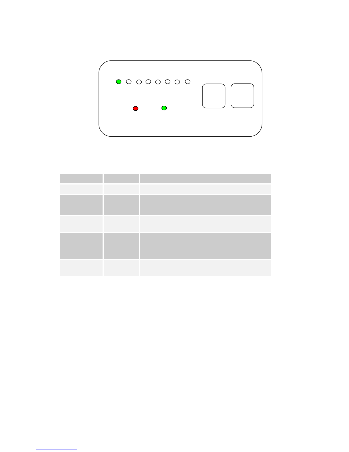
Receiver Panel Style 2, Fitted on Box Style 2.
Receiver LED and Button Meaning on panel Style 2
LED / Button
Colour
Meaning / Use
Alarm LED
Red
When lit indicates alarm or fault condition on equipment.
RF LED
Green
Receiver:
When lit indicates receiver has signal lock.
LED 1 to 8
Green
When lit permanently, indicates which of the eight stored
configurations is currently selected.
RF Button
-
Receiver:
Pressing the RF button enables/disables the on screen display
diagnostic function.
Config Button
-
The config button when pressed selects the next configuration from
memory.
1 2 3 4 5 6 7 8
RF
CONFIG
ALARM
RF
15
7.2 Getting Started with the Transmitter
Cables and Connections
This section describes how to connect the following domo model
numbers.
• SOL2TX-115140 (1.15 to 1.4GHz)
• SOL2TX-228255 (2.28 to 2.55GHz)
• SOL2TX-034047 (340 TO 470MHz)
• SOL2TX-057067 (575 to 675MHz)
• SOL2TX-488515 (4.88 to 5.1GHz)
• SOL2TX-560590 (5.6 to 5.9GHz)
• SOL2TX-310340 (3.1 to 3.4GHz)
• SOL2TXLE-138139 (1.389 to 1.399GHz)
• SOL2TXLE-240248 (2.4 to 2.483GHz)
• SOL4TX-115140 (1.15 to 1.4GHz)
•
SOL4TX-228255 (2.28 to 2.55GHz)
• SOL4TX-034047 (340 TO 470MHz)
• SOL4TX-057067 (575 to 675MHz)
• SOL4TX-488515 (4.88 to 5.1GHz)
• SOL4TX-560590 (5.6 to 5.9GHz)
• SOL4TX-310340 (3.1 to 3.4GHz)
• SOL4TXLE-138139 (1.389 to 1.399GHz)
• SOL4TXLE-240248 (2.4 to 2.483GHz)
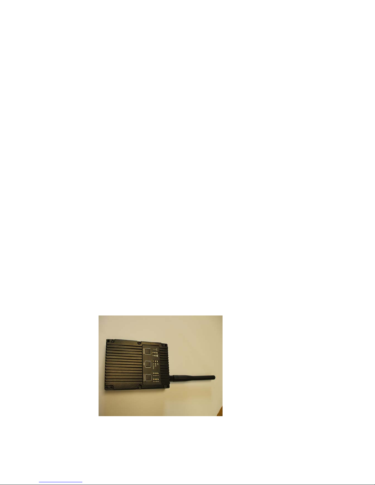
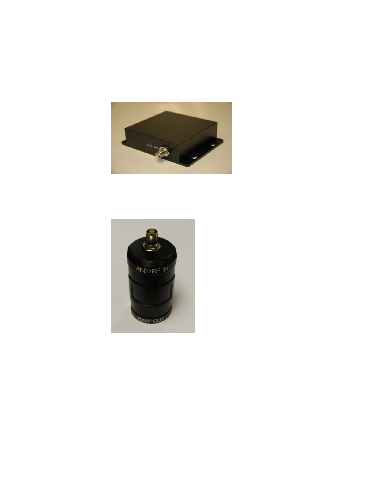
The picture below shows the domo SOLO2 and SOLO4 transmitter.
The domo transmitter is supplied with the following cables.
• Combined Video and Audio 2m
16
• Control 3m
• DC Power 2m
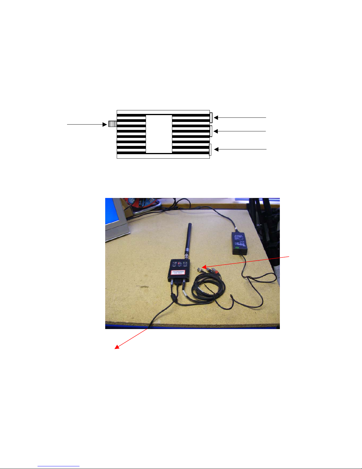
The domo transmitter should be connected as shown below.
As a typical example – including the control link from the PC,.
Audio Cable
Data and Control Cable
DC Power Cable
Antenna
To Computer
To Computer
To Camera

17
Video and Audio
Push the LEMO connector into the socket labelled ‘AV’, taking care to
align the connectors. Connect the video and audio sources.
Connector
Signal
Video BNC
75 ohm composite video source, PAL or NTSC
software selectable
Audio Plugs
Line / Microphone level audio, switchable.
Line level -2dBu clip level low impedance
source (< 600 ohm)
Microphone level 12, 24, 36 and 48dB preamp
stages software switchable
Microphone power is provided on the audio connectors at approximately 3V (suitable for
Electret microphones)
Typically the video source will be a small colour or black and white CCD
camera.
Typically the audio source will be an Electret microphone.
DC Power
The transmitter unit can be powered from a nominal 12V DC supply or
an AC to DC adapted supply.
Push the LEMO connector on the DC power cable into the socket
labelled 12V, taking care to align the connectors. Connect the banana
connectors on the other end of the ca
ble to a suitable DC source.
The 12V DC input has the following characteristics.
• Input Voltage Range – 5.9V to 16V, reverse voltage protected.
• Current draw - 0.48 to 0.4A at 12V (mode dependant)
domo can supply optional AC to DC converter blocks to power the
transmitter unit, the domo part number is PSU12
18
Antennas
domo transmitters are supplied as standard without antennas. An
antenna must be connected for normal operation. The transmitter unit is
supplied with a panel mounted SMA connector which carries the RF
output. The antenna should be connected by screwing it onto the SMA,
but care should be taken to not over tighten the connector.
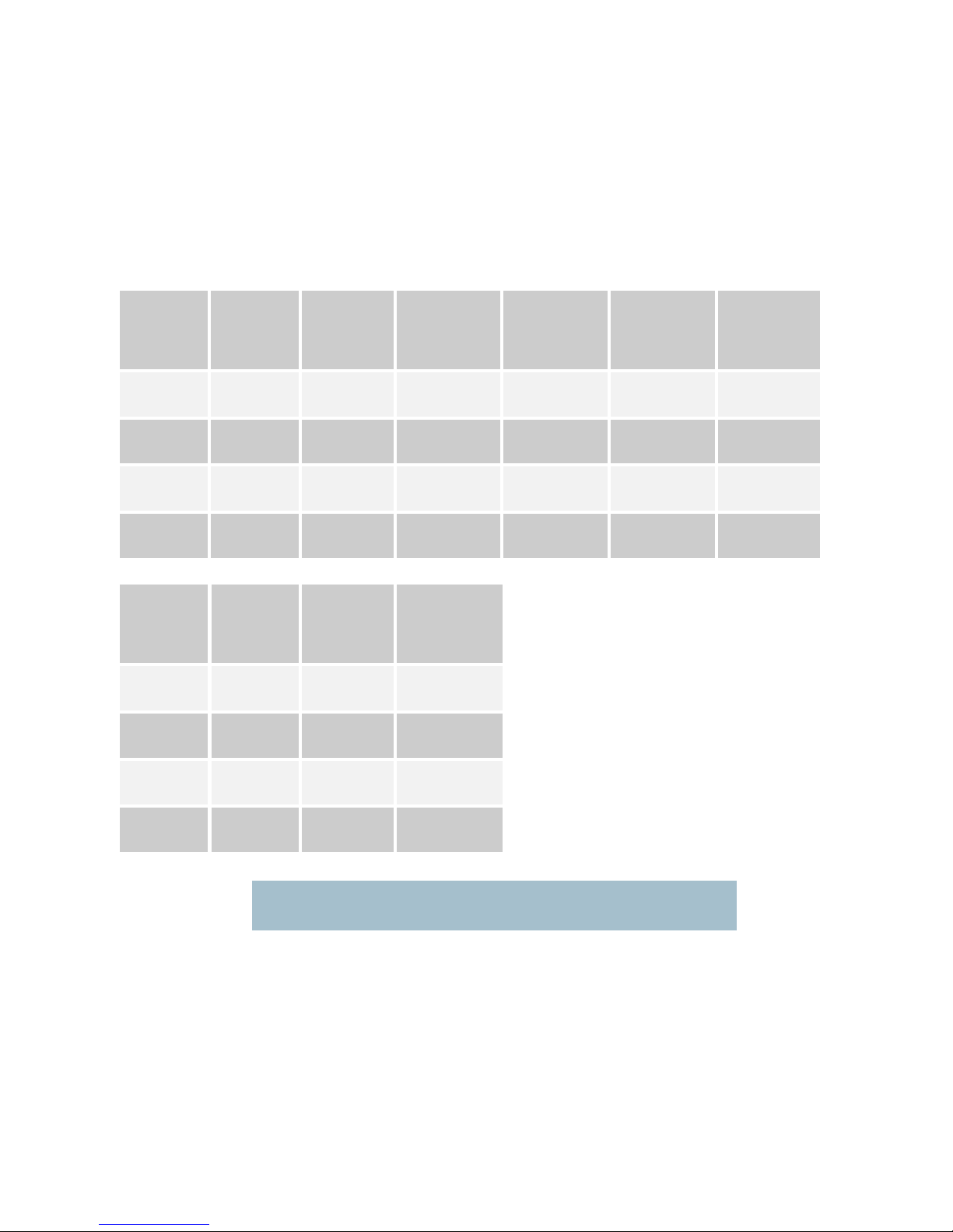
The transmitter has the following RF output characteristics.
RF Spec
Model
Number
ending 034047
Model
Number
ending 057067
Model
Number
ending 115140
Model
Number
ending 228255
Model
Number
ending 138139
Model
Number
ending 240248
Output
Frequency
340 to
470MHz
575 to
675MHz
1.15 to
1.40GHz
2.28 to
2.55GHz
1.389 to 1.399
GHz
2.400 to 2.483
GHz
Output
Bandwidth
2.5MHz
2.5MHz
2.5MHz
2.5MHz
2.5MHz
2.5MHz
Output
Power
100mW
(nominal)
100mW
(nominal)
100mW
(nominal)
100mW
(nominal)
100mW
(nominal)
10mW
(nominal)
Output
Impedance
50 ohm
50 ohm
50 ohm
50 ohm
50 ohm
50 ohm
RF Spec
Model
Number
ending 310340
Model
Number
ending 488515
Model
Number
ending 560590
Output
Frequency
3.1 to
3.4GHz
4.88 to
5.15GHz
5.6 to 5.9GHz
Output
Bandwidth
2.5MHz
2.5MHz
2.5MHz
Output
Power
100mW
(nominal)
100mW
(nominal)
100mW
(nominal)
Output
Impedance
50 ohm
50 ohm
50 ohm
Note. It is recommended that the antennas be connected directly to the transmitter unit.
The use of RF cables at this point will degrade the performance of the system.
The optimum choice of antenna will vary according to application. The
following table gives some suggestions for suitable transmit antennas
with the associated domo part number.

19
Application
Antenna model number
Mobile body worn application
1.00 to 1.40GHz - ANTBCL
2.28 to 2.50GHz - ANTBCS
Mobile vehicle application
1.00 to 1.40GHz – ANT4L
2.28 to 2.50GHz - ANT4S
4.80 to 5.15GHz – ANT6C
Long range point to point link
1.00 to 1.40GHz – ANT12L
2.28 to 2.50GHz – ANT12S
Note. When using antenna types ANT4L, ANT4S, ANT6C, ANT12L and ANT12S
with domo transmitters SMA to TNC adaptor connectors will be needed.
Other antennas for more specialist applications, such as aircraft use or
covert surveillance use are available on request from domo.
Control Cable
The control cable is used for connecting the transmitter unit to a PC
when using the domo PC control application. The PC control
application is described in more detail the Advanced Operation section
of this handbook.
Installation Notes
The domo transmitter has been designed specifically for body worn
applications; however it is a general-purpose wireless video transmitter
and can be used in many applications including the following.
• Body worn portable applications
• Vehicle based applications
This section gives guidelines for how to install the transmitter in the
above applications.
20
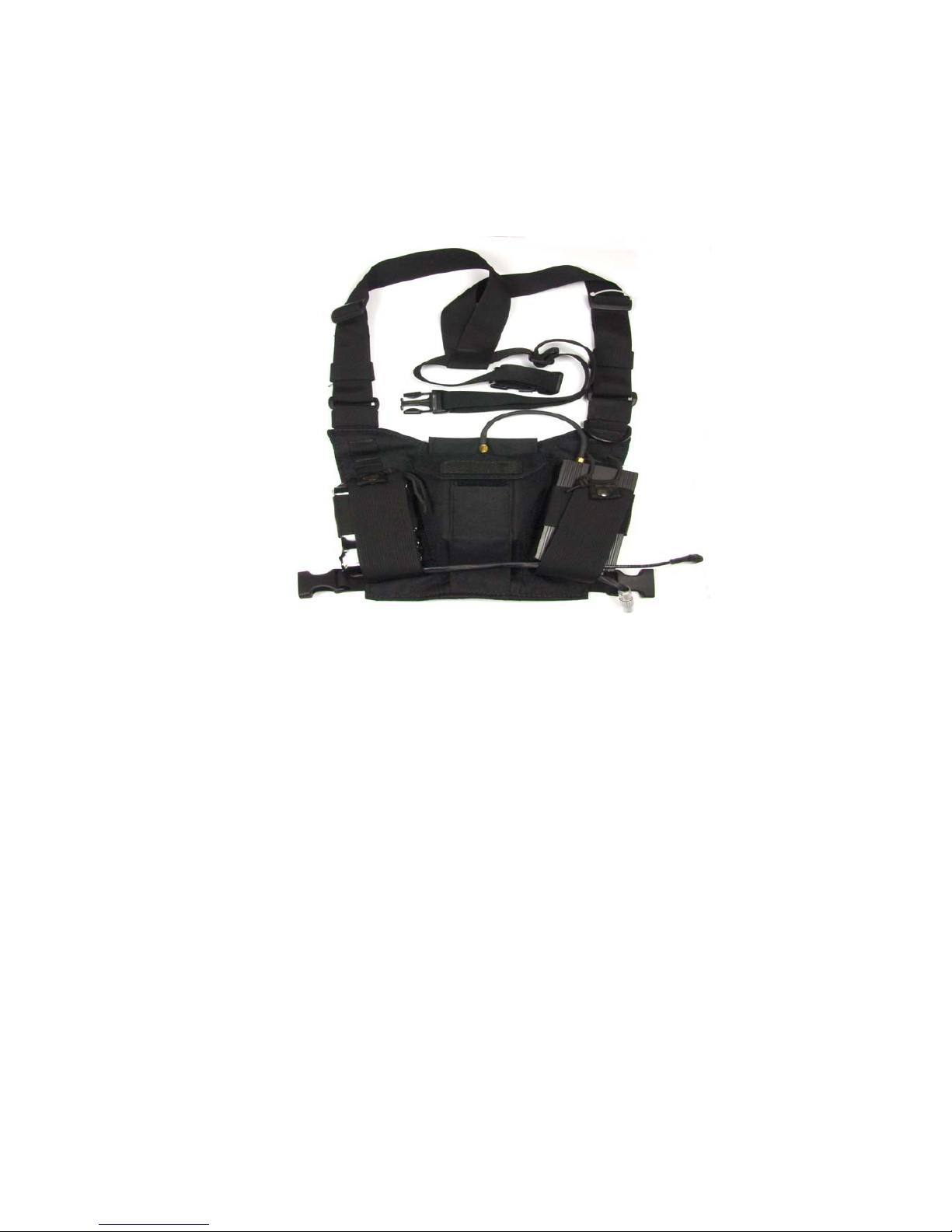
Body Worn Applications
Body worn applications will either be covert or overt and this will dictate
the style of antennas and mounting of cameras. For overt applications
domo can supply a harness as shown below (domo part number
ACCBCH)
With all body worn systems the antenna should be selected to transmit
power away from body and domo recommends the use of the domo
body worn antenna (part numbers ANTBCL and ANTBCS).
Experimentation has shown that unlike traditional analogue systems,
front and rear antennas are not normally required. The nature of
COFDM and its immunity to reflections will ensure that the signal
normally bounces back t
o the receive site even when the operators
body is between the transmit and receive antenna.
In covert applications, ultra slim patch antennas can be used. domo
does not supply patch antennas directly, but can recommend
manufacturers on request.
The SOLO4 and SOLO2 transmitter has been successfully tested with a
wide variety of standard and pinhole cameras. domo does not supply
cameras, but can recommend
suitable cameras and suppliers on
request.
The domo transmitter will become warm to the touch after prolonged
operation, and so insulation between the operators’ body and the
transmitter unit should be considered.
The SOLO2/SOLO4 transmitter is splash resistant, but is not
waterproof, so it should not be exposed to moisture for prolonged
periods.

21
Vehicle Applications
Typically, in vehicle applications, a greater range is required than with
body worn applications, therefore the use of additional power amplifiers
must be considered.
domo offers a range of power amplifiers. Interconnection between the
transmitter and any power amplifier should be kept as short as possible,
but where this is not possible, special attention should be taken to use
only
low loss cables. An appropriate cable might be RG213C/U. It is
essential to minimise the distance between the amplifier and the
antenna.
Mounting of the transmitter should use the mounting holes provided.
The transmitter is equipped with a self-regulating 5.9 to 16V input that
can be connected directly to the vehicle battery. Power conversion will
be required for 24V vehicles.
The video input can be con
nected across long video cable lengths so
remotely mounted cameras should pose no problem.
The transmitter is splash resistant, but is not waterproof, so it should not
be exposed to moisture for prolonged periods. The transmitter is selfcooling; however it should be mounted in a ventilated environment.
Forced air cooling is not required.

22
7.3 Getting Started with the SOLO Receiver
Connections
This section describes how to connect the following model numbers.
• SOL2RX
• SOL4RX
The SOLO receiver is normally purchased with Cobham Surveillance down-converters.
There are two versions of Cobham Surveillance domo downconverters; an older square box version and a later Barrel
Down-converter.
The square box variants have product codes DC-XXXXXX.
• DC-100140
• DC-225265
• DC-310340
It is the addition of the down-converters that makes the system
frequency specific.
The SOLO Receiver is supplied with the following components.
• Two RF cables, 3m
• Video cable 3m
• Audio cable 3m
• Control cable 3m
• AC / DC Power adapter
23
The picture below shows the two types of domo weatherproof down
converter.
L-Band and S-Band
Barrel down-converter
The Solo4 Receiver must be configured with the correct down-converter
Local Oscillator (LO) Frequency and down-converter LO side. These
numbers are specific to the type and frequency band of the downconverter.
The SOLO4 downconverter converts the received signal from
microwave frequencies to UHF frequency and applies gain allowing the
signal to run down cables without loss. This down-conversion allow
s
the domo SOLO Receiver to be mounted remotely from the receive
antennas. The down-converter is available as either a standard nominal
9dB gain model (DCB) or high gain variant (DCBX) nominal 19dB gain.

24
Square down-converter
New Style Barrel down-converter
NOTE : The LO Frequency setting in the SOLO4 Receiver controller has
changed compared to the older square L-Band (1.1 to 1.4GHz) and S-Band
(2.28 to 2.55GHz) products. The LO frequency MUST be set absolutely
correctly for the system to work properly. This can be set using the Solo4
Receiver controller software – see section 3.3 of this manual for details on
use of the controller.
RF Parameters
L-Band
DC-100140
S-Band
DC-225265
Frequency In
1000MHz
to
1500MHz
2250MHz
to
2650MHz
Local Oscillator
1700MHz
1880MHz
High Side or Low Side
High
Low
Gain (DC variant)
9dB
9dB
Gain (DCX variant)
19dB
19dB
RF Parameters
L-Band
DCB-100150
L-Band
DCB-150200
S-Band
DCB-200250
S-Band
DCB-250300
3GHz
DCB-300350
C-Band
DCB-450500
C-Band
DCB-550600
Frequency In
1000MHz
to
1500MHz
1500MHz
to
2000MHz
2000MHz
to
2500MHz
2500MHz
to
3000MHz
3000MHz
to
3500MHz
4500MHz
to
5000MHz
5500MHz
to
6000MHz
Local Oscillator
1800MHz
2300MHz
1700MHz
2200MHz
2700MHz
4200MHz
5200MHz
High Side or
Low Side
High
High
Low
Low
Low
Low
Low
Gain (DCB
variant)
9dB
9dB
9dB
9dB
9dB
9dB
9dB
Gain (DCBX
variant)
19dB
19dB
19dB
19dB
19dB
19dB
19dB
25
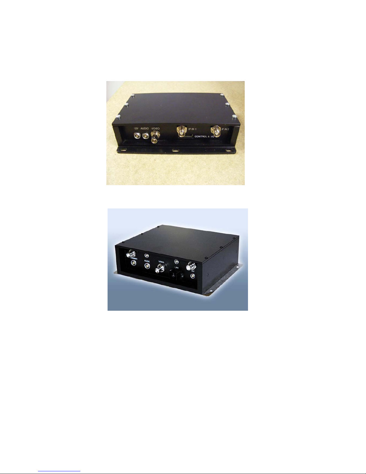
There are two styles of domo SOLO receiver box shown below.
domo SOLO receiver with Box style 1.
domo SOLO receiver with Box style 2.
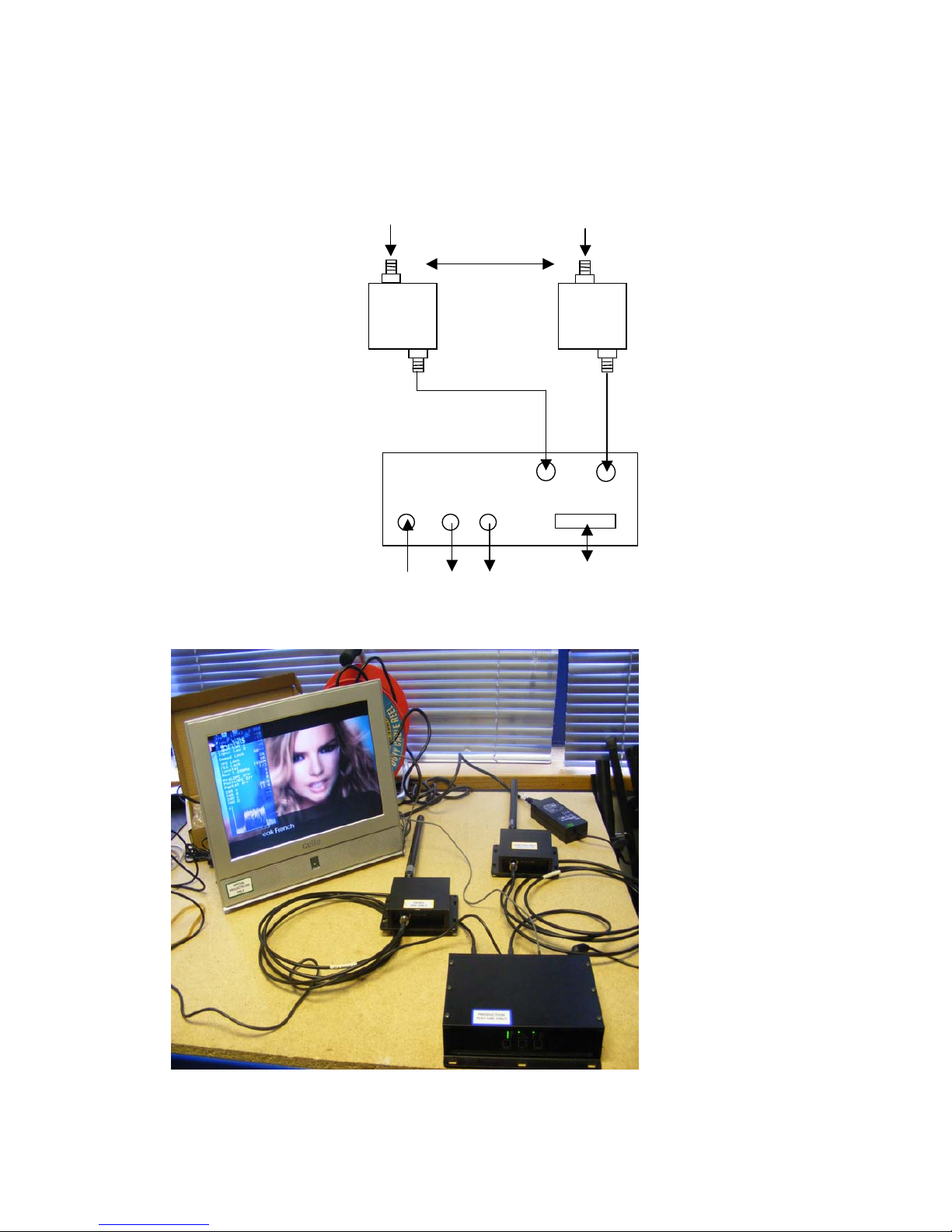
26
The domo SOLO2/4 receiver system with panel style 1 should be
connected as shown below.
IF In1
IF IN2
DC
Audio
Video
Control, data and
Chaining
Antenna 1
Antenna 2
3m TNC Cable
3m TNC Cable
DC
Cable
Video
Cable
Audio
Cable
100 cm
27
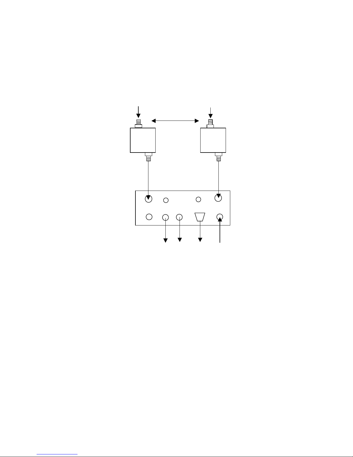
The domo SOLO2/4 receiver system with panel style 2 should be
connected as shown below.
IF In1
IF IN2
DC
Audio
Video
Control
Antenna 1
Antenna 2
3m TNC Cable
3m TNC Cable
DC
Cable
Video
Cable
Audio
Cable
100 cm
LAN
Cable
Chain
LAN
Data

28
Diversity, Antenna Positioning and Use of Down Converters
Note: Domo down converters can be damaged by static electricity discharge when
connecting antennas. It is suggested that only antennas with built in DC path to ground
are employed to avoid static damage. If this can not be achieved then antennas should be
shorted to ground before connection to the down converter.
The domo SOLO2/SOLO4 receiver is a diversity receiver and will give
optimum results only when two antennas are deployed. The downconverter boxes should be connected to the receiver, by connecting the
3m TNC cables supplied between the down converter connector
labelled ‘RX / IF OUT’ and the receiver connector labeled ‘IF IN’. Care
should be taken not to over tighten the TNC connectors.
The down-conve
rters convert the RF signal down from microwave
frequencies to the UHF band, which allows the signals to be run along
longer cables without degradation. In the case of the standard domo
SOLO receiver 3 metre long cables are provided, allowing the downconverters to be positioned remotely from the receiver.
It is important that the down-converter be positioned very close to the
antenna - long cables sh
ould not be used between the antenna and the
down converter because this can degrade system performance.
Typically antennas and down converters will be positioned outside,
usually on the roof of a building or a vehicle. The down-converters can
be located outside, because they are weather proof. However the
receiver is not weather proof and the 3 metre cables should be used to
allow the receiver to be
positioned in an equipment room, rack or
housing.
The domo SOLO2/SOLO4 receiver uses an advanced diversity
technique called maximum ratio combining to construct a good
spectrum from two potentially damaged received signals. To get the
best results from diversity, the antennas should be physically separated
by at least 100cm.
Sometimes better results can be achieved by separating the antennas
further, or
by positioning them of different corners of a building. The
optimum antenna placement depends on the environment in which the
equipment is used and the signal path, and is often limited by physical
factors (accessibility for example).
The domo SOLO2/SOLO4 receiver is supplied without antennas since
the optimum choice of antenna will depend on the operational scenario.
For short range or mobile applicati
ons, omni directional antennas such
as ANT4L, ANT6C or ANT4S will be most suitable whereas for longer
range fixed links, or where mobile transmit activity is happening in a
defined 120 degree arc the higher gain ANT12L or ANT12S will be
more suitable.
Antennas should be screwed directly to the TNC input of the down
converter labeled ‘ANT/RF IN’.
Video Output Connection
Connect the video output lead to the BNC connector labeled ‘VIDEO’ on
the SOLO receiver and to the chosen video display device.

29
Connector
Signal
Video BNC
75 ohm composite video output, PAL or NTSC
software selectable at the transmitter
Typically the video display device will be a high quality monitor.
Audio Connection
Push the LEMO connector into the socket labeled ‘AUDIO’, taking care
to align the connectors and connect the chosen audio output device.
Connector
Signal
Audio Plugs
Line level, +7dBu clip level, low impedance
source (20 ohm)
Typically the audio output device will be monitoring speakers.
DC Power
The SOLO2/SOLO4 Receiver is powered from a nominal 12V DC
supply.
As standard domo supply an AC to DC converter, terminated with a
LEMO connector on the DC power output. Push the LEMO plug into the
socket labelled ‘12V’, taking care to align the connectors. Connect the
AC adapter block to your local mains electricity supply, noting the mai
ns
supply requirements detailed on the adapter.
The 12V DC input has the following characteristics.
For Box style 1.
• Input Voltage Range – 9V to 16V, reverse voltage protected.
• Current Draw – 0.9A at 12V
For Box style 2.
• Input Voltage Range – 10V to 18V, reverse voltage protected.
• Current Draw – 1.0A at 12V
domo can supply optional bare DC power leads, for connection or
hardwiring to other DC source
s. The domo part number is CABDC3

30
Control Cable
The control cable is used for connecting the SOLO receiver to a PC
when using the domo PC control application. The PC control
application is described in more detail the Advanced Operation section
of this handbook.
Data Connection
The SOLO receiver features a general purpose DATA port used for
outputting RS232 data transmitted from a SOLO2/4 transmitter.
Installation Notes
The domo SOLO receiver has been designed so that the downcon
verter units are mounted remotely from the receiver unit, and
connected via the 3 metre TNC cable.
The down-converter units should be connected directly to the receive
antenna, but where this is not possible a short length of low loss RF
cable such RG213C/U should be used. System performance will be
degraded by the introduction of RF losses at this point.
The down converter should be screwed or strapped
to a flat surface or
pole, using the integral mounting holes on the unit. The down converter
is weather proof, and has no special cooling requirements. If the downconverter is mounted where it is exposed to the weather then the
connector labelled ‘ANT / IN’ should face upwards.
The antenna itself should be separately secured, the TNC connectors
should not be expected to take the strain of the anten
na.
The domo SOLO2/SOLO4 receiver is designed to be mounted in an
equipment rack or shelter and must not be exposed to the elements.
The receiver is splash resistant, but is not waterproof, so it should not be
exposed to moisture for prolonged periods.
The receiver is self-cooling; however it should be mounted in a
ventilated environment. Forced air cooling is not required. Adequate
clearance on either
side the receiver (5cm) should be allowed for
ventilation.
The receiver is supplied with a mounting plate that allows the unit to be
screwed or strapped to a flat surface.
 Loading...