

SAILOR Fleet One
User & installation manual

98-141368-A ii
Document number: 98-141368-A
Release date: 4 April 2014
Disclaimer
Any responsibility or liability for loss or damage in connection with the use of this product and the
accompanying documentation is disclaimed by Thrane & Thrane A/S. The information in this manual is
provided for information purposes only, is subject to change without notice and may contain errors or
inaccuracies. Manuals issued by Thrane & Thrane A/S are periodically revised and updated. Anyone
relying on this information should acquire the most current version e.g. from www.cobham.com/satcom >
Service and support, or from the distributor. Thrane & Thrane A/S is not responsible for the content or
accuracy of any translations or reproductions, in whole or in part, of this manual from any other source.
In the event of any discrepancies, the English version shall be the governing text.
Thrane & Thrane A/S is trading as Cobham SATCOM.
Copyright © 2014 Thrane & Thrane A/S. All rights reserved.
Trademark acknowledgements:
• SAILOR is a registered trademark of Thrane & Thrane A/S in the European Union, the United States
and other countries.
• Windows is a registered trademark of Microsoft Corporation in the United States and other
countries.
• Inmarsat is a registered trademark of International Maritime Satellite Organisation (IMSO) and is
licensed by IMSO to Inmarsat Limited and Inmarsat Ventures plc.
• Inmarsat’s product names are trademarks or registered trademarks of Inmarsat.
• Other product and company names mentioned in this manual may be trademarks or trade names of
their respective owners.
Company web site
www.cobham.com/satcom

98-141368-A iii
Safety summary 1
The following general safety precautions must be observed during all phases of operation, service
and repair of this equipment. Failure to comply with these precautions or with specific warnings
elsewhere in this manual violates safety standards of design, manufacture and intended use of the
equipment. Thrane & Thrane A/S assumes no liability for the customer's failure to comply with
these requirements.
Observe marked areas
Under extreme heat conditions do not touch areas of the terminal or
antenna that are marked with this symbol, as it may result in injury.
Microwave radiation hazards
During transmission the antenna in this system radiates Microwave
Power.This radiation may be hazardous to humans close to the antenna.
During transmission, make sure that nobody gets closer than the recommended minimum safety
distance.
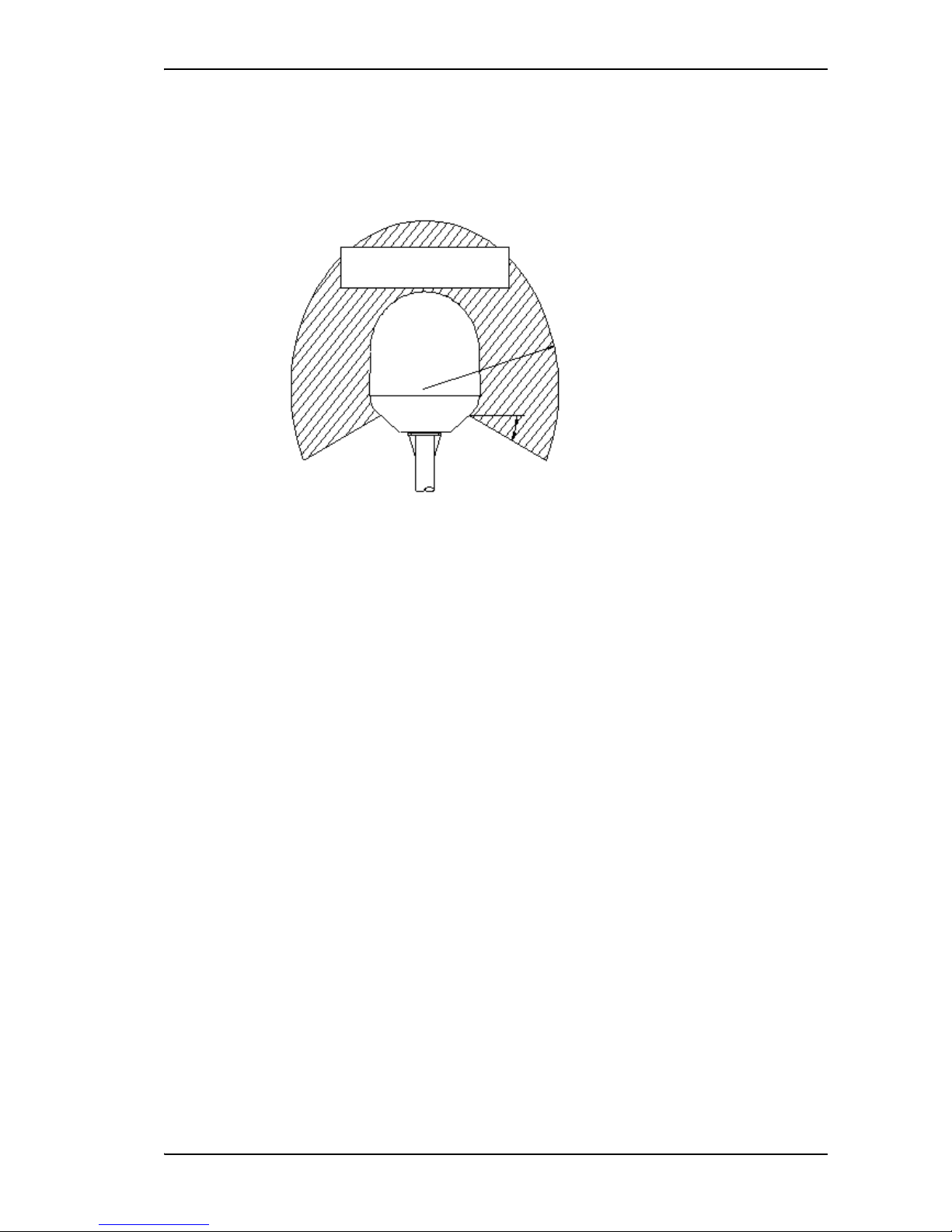
On the SAILOR Fleet One, the minimum safety distance to the antenna
panel on the focal line is 0.6 m, based on a radiation level of 10 W/m2.
The radiation level is 100 W/m2 at a distance of 0.2 m from the
antenna panel. Refer to the drawing below.
Pour une antenne SAILOR Fleet One, la distance de sécurité minimale
avec le panneau de l'antenne sur l'axe focal est de 0.6 m, sur la base d'un
niveau de radiation émis de 10 W/m2. L'appareil génère un niveau de radiation de 100 W/m2 à une
distance de 0.2 m de l'avant du panneau de l'antenne. Veuillez consulter le schéma au-dessous.
Distance to other equipment
Do not move the antenna closer to radars than the min. safe distance specified in the installation
manual - it may cause damage to the antenna.
MICROWAVE RADIATION
No personnel within safety distance
Safety distance:
0.6 m, 10 W/m
2
0.2 m, 100 W/m
2
60

98-141368-A iv
Compass Safe Distance:
SAILOR Fleet One terminal: min. 0.3 m.
SAILOR Fleet One antenna: min. 1.2 m
Service
User access to the interior of the system units is prohibited. Only a technician authorized by
Cobham SATCOM may perform service - failure to comply with this rule will void the warranty.
Do not service or adjust alone
Do not attempt internal service or adjustments unless another person, capable of rendering first aid
resuscitation, is present.
Grounding, cables and connections
To minimize shock hazard, the equipment chassis and cabinet must be connected to an electrical
ground. The terminal must be grounded to the ship. For further grounding information refer to the
Installation manual.
Do not extend the cables beyond the lengths specified for the equipment. The cable between the
terminal and antenna can be extended if it complies with the specified data concerning cable
losses etc.
All cables for the SAILOR Fleet One system are shielded and should not be affected by magnetic
fields. However, try to avoid running cables parallel to AC wiring as it might cause malfunction of
the equipment.
Power supply
The voltage range is 10.5 - 32 V DC; 11.5 A - 4 A. It is recommended that the voltage is provided
by the 24 V DC bus on the ship. Be aware of high start-up peak current: 20 A@24 V, 5 ms.
If a 24 V DC power bus is not available, an external 115/230 VAC to 24 V DC power supply can be
used.
Do not operate in an explosive atmosphere
Do not operate the equipment in the presence of flammable gases or fumes. Operation of any
electrical equipment in such an environment constitutes a definite safety hazard.
Keep away from live circuits
Operating personnel must not remove equipment covers. Do not replace components with the
power cable connected. Under certain conditions, dangerous voltages may exist even with the
power cable removed. To avoid injuries, always disconnect power and discharge circuits before
touching them.
Failure to comply with the rules above will void the warranty!

98-141368-A v
Related documents
The below list shows the documents related to this manual and to the SAILOR Fleet One system.
Typography
In this manual, typography is used as indicated below:
Bold is used for the following purposes:
• To emphasize words.
Example: “Do not touch the antenna”.
• To indicate what the user should select in the user interface.
Example: “Select SETTINGS > LAN”.
Italic is used to emphasize the paragraph title in cross-references.
Example: “For further information, see Connecting Cables on page...”.
Title and description
Document
number
SAILOR Fleet One, Installation guide
A short guide to installing the SAILOR Fleet One system
98-141370
SAILOR Fleet One, Quick guide
A short guide to the most important functions of the
SAILOR Fleet One system
98-141369
IP Handset, User manual
Explains the features and functions of the IP Handset. The IP
Handset works as a standard IP handset, but also serves as a user
interface for the SAILOR Fleet One system.
98-126059

98-141368-A vi
Table of contents
Chapter 1 Introduction
Your SAILOR Fleet One ................................................................................................................. 1
Features and interfaces ................................................................................................................ 2
Main units .............................................................................................................................................. 3
Tools for setup and use ................................................................................................................ 4
Available services ............................................................................................................................. 4
Chapter 2 Installation
Unpack your SAILOR Fleet One .............................................................................................. 6
Mounting considerations for the antenna ....................................................................... 7
Antenna mast design ...................................................................................................................11
Install the antenna .........................................................................................................................13
Mounting considerations for the terminal .....................................................................16
Install the terminal ........................................................................................................................17
Connect cables ................................................................................................................................21
Power cable selection ..................................................................................................................34
Chapter 3 Get started
Start up the SAILOR Fleet One ..............................................................................................37
Connect a smartphone ...............................................................................................................39
Connect an IP handset ...............................................................................................................41
Connect an analogue phone ...................................................................................................42
Connect a computer ....................................................................................................................42
Make a call ..........................................................................................................................................43
Connect to the Internet .............................................................................................................44
Chapter 4 Operation
Phone calls ..........................................................................................................................................45
Data connection .............................................................................................................................49
The built-in web interface ........................................................................................................51
Dashboard ...........................................................................................................................................54

Table of contents
98-141368-A vii
Phone book ........................................................................................................................................57
Call log ...................................................................................................................................................59
SMS messages ..................................................................................................................................60
SIM PIN ................................................................................................................................................63
Chapter 5 Configuration
Set up the data connection .....................................................................................................67
Set up the interfaces ....................................................................................................................68
Select a preferred satellite ........................................................................................................73
Log on as administrator ..............................................................................................................74
Save or load a configuration ...................................................................................................77
Call charges ........................................................................................................................................78
Log handling ......................................................................................................................................79
Data limits ...........................................................................................................................................79
Configure the SIM PIN ...............................................................................................................80
Set up user permissions ..............................................................................................................82
Restricted dialling ...........................................................................................................................83
External data connections ........................................................................................................85
Track the SAILOR Fleet One ....................................................................................................87
Antenna RF noise filter ...............................................................................................................89
Chapter 6 Maintenance and troubleshooting
Get support .........................................................................................................................................90
Update software .............................................................................................................................91
Part numbers .....................................................................................................................................93
Troubleshooting guide ................................................................................................................94
Status signalling ...............................................................................................................................96
Generate a diagnostic report ..................................................................................................97
Event messages ...............................................................................................................................98
Extended status ............................................................................................................................105
Antenna properties ....................................................................................................................105
Self test ..............................................................................................................................................106

Table of contents
98-141368-A viii
Reset button ...................................................................................................................................107
List of reserved subnets ...........................................................................................................109
App. A Technical specifications
SAILOR Fleet One antenna ....................................................................................................110
SAILOR Fleet One terminal ....................................................................................................114
Glossary ...................................................................................................................................................................118
Index ...................................................................................................................................................................121

98-141368-A 1
Chapter 1
Introduction
1
Your SAILOR Fleet One
Congratulations on the purchase of your SAILOR Fleet One System!
SAILOR Fleet One is a maritime broadband system, providing simultaneous high-speed data
and voice communication via satellite, using Inmarsat BGAN (Broadband Global Area Network).
Used with a phone or computer the SAILOR Fleet One gives you access to:
• Internet browsing
•E-mail
•Phone services
•File transfers
• VPN (Virtual Private Network) access to corporate servers
This chapter has the following sections:
• Features and interfaces
• Main units
• Tools for setup and use
• Available services

Chapter 1: Introduction
98-141368-A 2
Features and interfaces
The SAILOR Fleet One system offers the following features and interfaces:
Simultaneous voice and data communication over BGAN
Full duplex, single or multi-user, up to: 100 kbps
Standard Voice (4 kbps)
2 LAN (Local Area Network) ports with PoE (Power over Ethernet) for connecting
computers, e-hubs, IP handsets, WLAN access point etc.
1 Standard Phone port
1 multi-purpose I/O connector with 5 configurable inputs/outputs
1 SIM slot for your Fleet One SIM card
Built-in DHCP/NAT router
Built-in web interface for managing phone book, messages and calls, and configuration
Input power: 10.5 - 32 V DC (11.5 A - 4 A)
CE certified
ATC resilient
Supports Inmarsat’s extended L-band services, Inmarsat-XL
Wireless device
WLAN access point
External equipment,
e.g. fishery reporting
IP handset
Computer
LAN interface
(PoE)
Phone interface
Chapter 1: Introduction
98-141368-A 3
Main units
Units included
The SAILOR Fleet One system includes the following main units:
• SAILOR Fleet One antenna
• SAILOR Fleet One terminal
• Optional: IP Handset
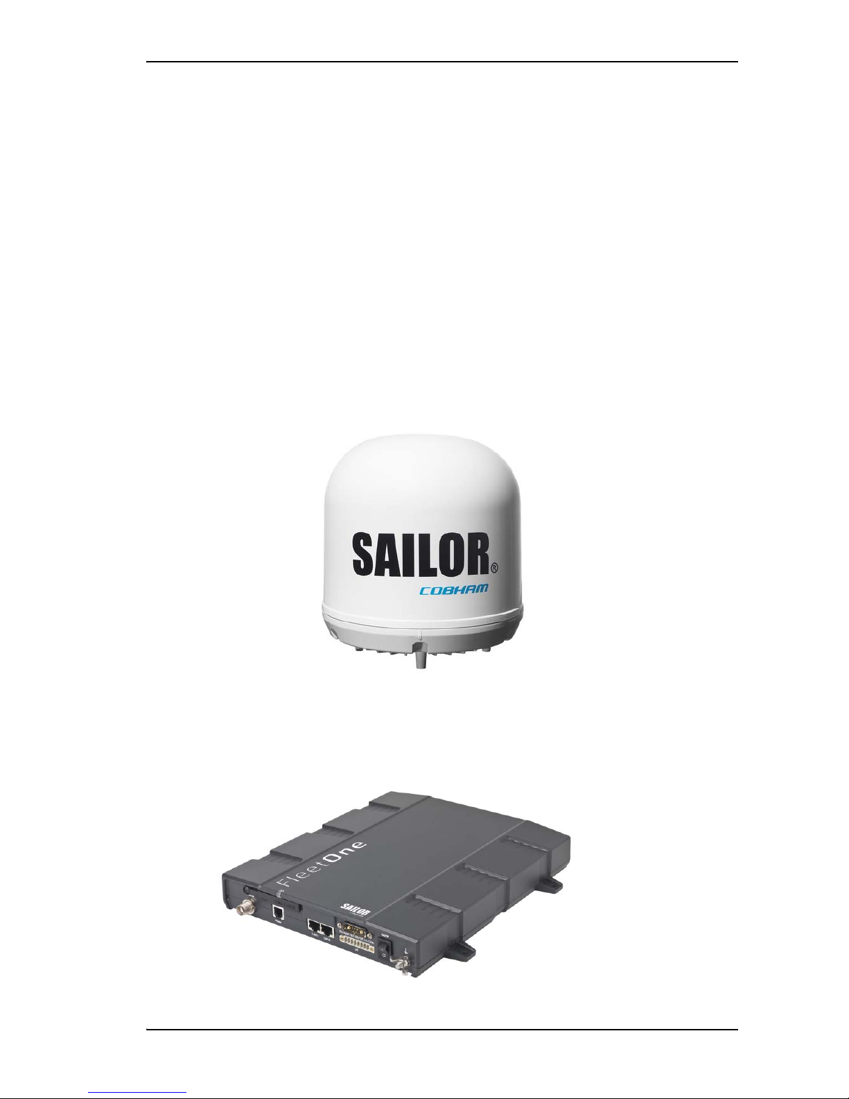
SAILOR Fleet One antenna
The SAILOR Fleet One system uses the SAILOR Fleet One antenna, which is a small size
maritime 2-axis stabilized BGAN antenna.
For information on how to install the antenna, see Chapter 2, Installation.
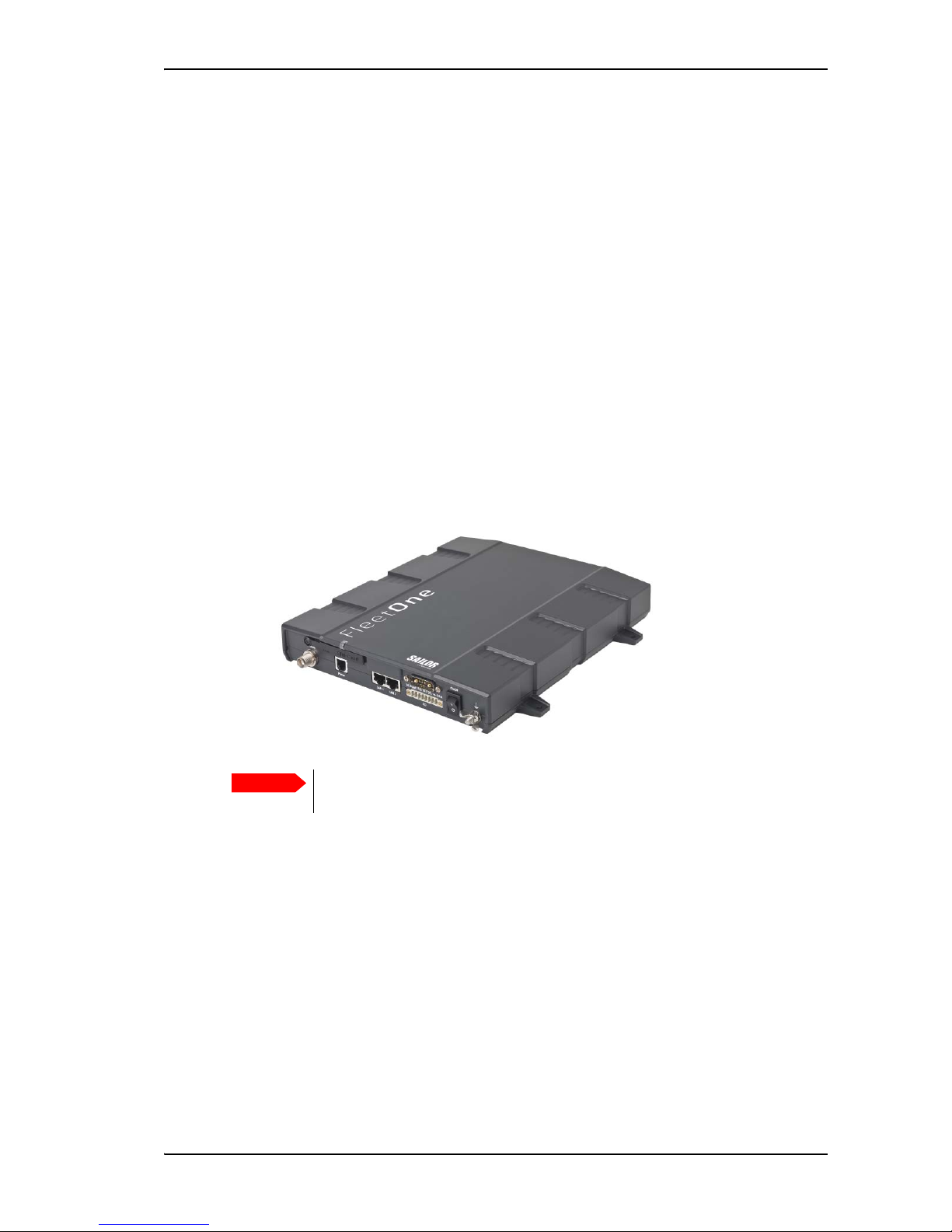
SAILOR Fleet One terminal
The SAILOR Fleet One terminal is the controlling unit in the SAILOR Fleet One system. It
contains all user interfaces and a power LED indicator and stores configuration data.

Chapter 1: Introduction
98-141368-A 4
SIM card
The terminal has a SIM (Subscriber Identity Module) slot located in the connector panel
behind a small cover plate. The terminal requires a dedicated SAILOR Fleet One SIM card,
which you get from your airtime provider.
The system requires a SIM card to go online and to access the settings of the terminal.
However, using the web interface you can view the Dashboard and upload software without
inserting a SIM card.
Router function
The SAILOR Fleet One terminal has a router function which routes traffic between the local
network connected to the terminal and network connections on the BGAN network.
The router contains NAT (Network Address Translation) which allows sharing of a public IP
address between a number of local network users.
Tools for setup and use
The built-in web interface in the terminal is used for easy configuration and daily use. The
web interface is accessed from a computer connected to the terminal, using an Internet
browser. No installation of software is needed.
For details on the web interface, see The built-in web interface on page 51.
The ThraneLINK Management Application (TMA) is a Windows program that provides
monitoring and software update of connected Cobham SATCOM devices with ThraneLINK
support. The devices must be on the same LAN.
If you have an IP Handset (minimum version 1.8) from Cobham SATCOM, it can be used for
displaying status, accessing a subset of controls and views and entering the PIN code for the
terminal. The IP Handset connects to the LAN interface of the terminal. For information on
how to use the IP Handset, see the user manual for the IP Handset (listed in Related
documents on page v).
Available services
Fleet One is a maritime broadband service providing the following services through the
Inmarsat BGAN system:
• Data connection to the Internet. A data connection which several users can share
simultaneously. The user pays for the amount of data sent and received.
• Phone connection. A standard phone connection for making calls over the BGAN
network.
• SMS. A Short Messaging Service for sending and receiving SMS messages to and from the
terminal.

Chapter 1: Introduction
98-141368-A 5
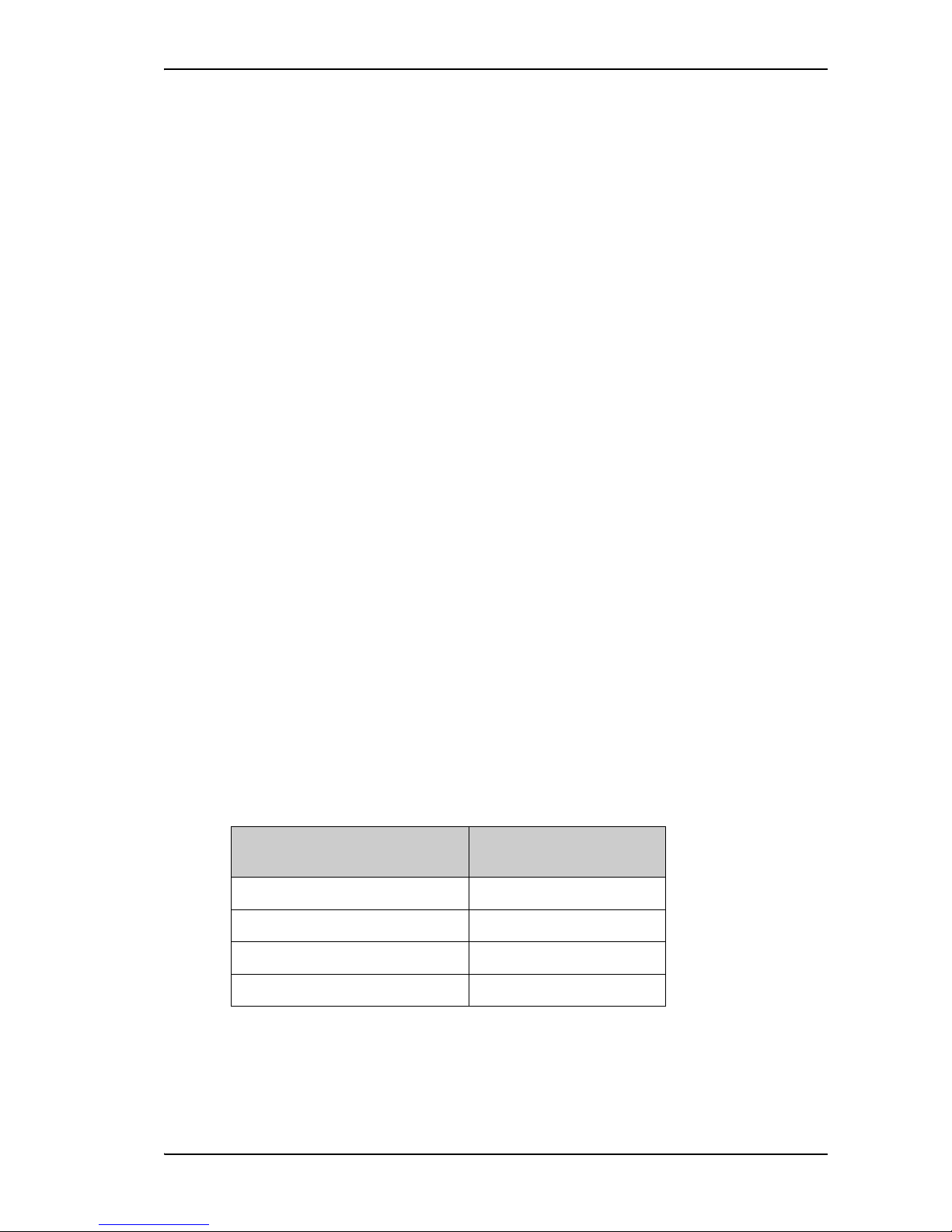
Access to services and interfaces
The following table shows which equipment and connectors you can use to access the services
listed in the left column.
Satellite coverage
The coverage map below shows satellite coverage and rate regions for the Fleet One service at
the time of writing. For updated information on coverage, see inmarsat.com.
Service
Connector on terminal
Phone LAN (PoE)
Data
-
Computer or WLAN access point
Standard voice Analogue phone IP handset or
smartphone via WLAN access point
SMS
-
Computer accessing the web
interface of the terminal.
0°
10°
20°
30°
40°
50°
60°
70°
80°
90°
10°
20°
30°
40°
50°
60°
70°
80°
90°
0°20°40°60°80°100°120°140°160°180° 20° 40° 60° 80° 100° 120° 140° 160° 180°
Home Region Rate Out of Region Rate
inmarsat.com
Fleet One coverage and rate regions
This map depicts Inmarsat’s expectations of coverage, but does not represent a guarantee
RIVHUYLFH7KHDYDLODELOLW\RIVHUYLFHDWWKHHGJHRIFRYHUDJHDUHDVpXFWXDWHVGHSHQGLQJ
on various conditions. Fleet One coverage rate regions March 2014.

98-141368-A 6
Chapter 2
Installation
2
This chapter describes how to install the SAILOR Fleet One antenna and the SAILOR Fleet One
terminal. It has the following sections:
• Unpack your SAILOR Fleet One
• Mounting considerations for the antenna
• Antenna mast design
• Install the antenna
• Mounting considerations for the terminal
• Install the terminal
• Connect cables
• Power cable selection
Unpack your SAILOR Fleet One
Unpack your SAILOR Fleet One system and check that the following items are present:
• SAILOR Fleet One terminal
• SAILOR Fleet One antenna
•DC power cable (1 m)
• Antenna cable (10 m)
• Ethernet cable (2 m)
• I/O connector
• Mounting bolts and washers for the antenna
• Kit for water protection of antenna connector joint
• Installation guide
•Quick guide
• CD with Installation guide, Quick guide and User & installation manual
• Optional: IP Handset
Inspect all units and parts for possible transport damage.

Chapter 2: Installation
98-141368-A 7
Mounting considerations for the antenna
When looking for a place to mount the SAILOR Fleet One antenna, make the following
considerations:
• Do not place the antenna close to large objects that may block the signal. Place the
antenna with free line of sight in all directions to ensure proper reception of the satellite
signal.
• Place the antenna in such a way that persons are not exposed to radiation from the
antenna. Keep the minimum safety distance. See Safety summary on page iii.
• Do not place the antenna within range of other equipment that can interfere with the
SAILOR Fleet One.
• Do not place the antenna close to a funnel, as smoke deposits are corrosive. Furthermore,
deposits on the radome can degrade performance.
• Do not block the drainage gasket in the bottom centre of the antenna. Leave space below
the antenna to allow any water to escape.
The following sections describe the details for the mounting considerations.
Obstructions
The antenna rotates 360° and down to -60° in pitch and roll, to allow for continuous pointing
even in heavy sea conditions. Any objects within this field can cause signal degradation.
The amount of degradation depends on the size of the object and the distance from the
antenna. As a rule of thumb any object that covers an angle of less than 3° at the antenna has
limited effect. The table below gives a guideline for the distance and maximum size of blocking
objects in order to avoid degradation.
Distance of object Maximum size of object
3m 16cm
5m 26cm
10 m 52 cm
20 m 104 cm
Chapter 2: Installation
98-141368-A 8
Radiation hazard
The SAILOR Fleet One antenna radiates 16.1 dBW EIRP. This translates to a minimum safety
distance of 0.6 m from the antenna while it is transmitting, based on a radiation level of
10 mW/cm
2
.
Interference
The antenna must be mounted as far away as possible from the ship’s radar and high power
radio transmitters (including other Inmarsat based systems), because they may compromise
the antenna performance. RF emission from radars might actually damage the antenna.
The SAILOR Fleet One antenna itself may also interfere with other radio systems. Especially
other Inmarsat systems and GPS receivers with poor frequency discrimination are vulnerable
to the radiation generated by the SAILOR Fleet One antennas.
Radar
It is difficult to give exact guidelines for the minimum distance between a radar and the
antenna because radar power, radiation pattern, frequency and pulse length/shape vary from
radar to radar. Further, the antenna is typically placed in the near field of the radar antenna and
reflections from masts, decks and other items in the vicinity of the radar are different from ship
to ship.
However, it is possible to give a few guidelines:
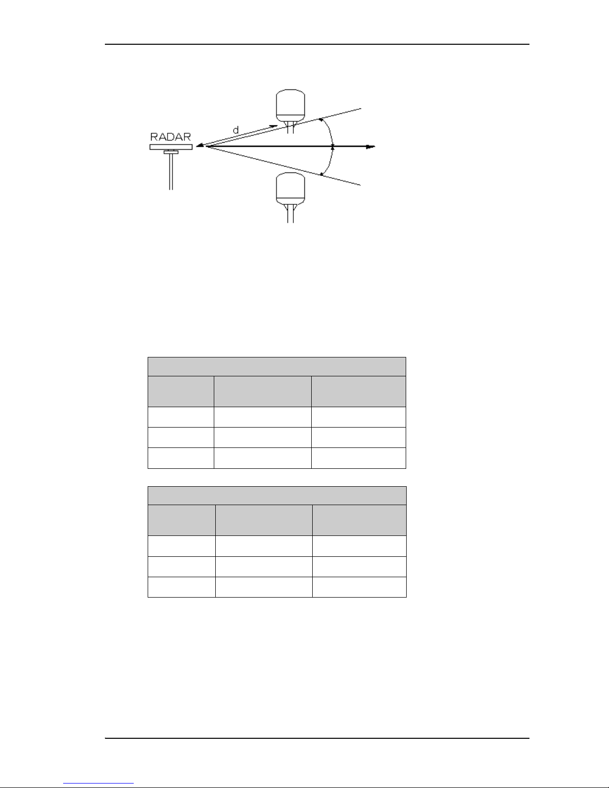
Since a radar radiates a fan beam with a horizontal beam width of a few degrees and a vertical
beam width of up to +/- 15°, the worst interference can be avoided by mounting the antenna
at a different level – meaning that the antenna is installed minimum 15° above or below the
radar antenna. Due to near field effects the benefit of this vertical separation could be reduced
at short distances (below approximately 10 m) between radar antenna and the
SAILOR Fleet One antenna. Therefore it is recommended to ensure as much vertical separation
as possible when the SAILOR Fleet One antenna has to be placed close to a radar antenna.
MICROWAVE RADIATION
No personnel within safety distance
60
Safety distance:
(0.2 m, 100 W/m
2
)
0.6 m, 10 W/m
2
Chapter 2: Installation
98-141368-A 9
Radar distance
The minimum acceptable separation (d min.) between a radar and the antenna is determined
by the radar wavelength/frequency and the power emitted by the radar. The tables below show
some “rule of thumb” minimum separation distances as a function of radar power at X and S
band. If the d min. separation listed below is applied, antenna damage is normally avoided.
“d min.” is defined as the shortest distance between the radar antenna (in any position) and the
surface of the SAILOR Fleet One antenna.
The separation distance for C-band (4-8 GHz) radars should generally be the same as for Xband radars.
Min. 15
Min. 15
X-band (~ 3 cm / 10 GHz) damage distance
Radar power
d min. at 15°
vertical separation
d min. at 60°
vertical separation
0 – 10 kW 0.8 m 0.4 m
30 kW 2.4 m 1.2 m
50 kW 4.0 m 2.0 m
S-band (~ 10 cm / 3 GHz) damage distance
Radar power
d min. at 30°
vertical separation
d min. at 75°
vertical separation
0 – 10 kW 0.4 m 0.2 m
30 kW 1.0 m 0.5 m
50 kW 2.0 m 1.0 m
Chapter 2: Installation
98-141368-A 10
Radar interference
Even at distances greater than “d min.” in the previous section the radar might still be able to
degrade the performance of the SAILOR Fleet One system.
The presence of one or more X-band radars within a radius up to 100 m could cause a minor
degradation of the signal-to-noise ratio during high speed and data calls. The degradation will
be most significant at high radar pulse repetition rates.
As long as receiving conditions are favourable, this limited degradation is without importance.
However, if receiving conditions are poor – e.g. due to objects blocking the signal path, heavy
rainfall or icing, low satellite elevation and violent ship movements – the small extra
degradation due to the radar(s) could cause poor call quality. A voice call might become noisy
or fail while a data connection might decrease in speed and performance.
The presence of S-band radar(s) is unlikely to cause any performance degradation – as long as
the minimum distances (d min.) listed in the previous section are applied.
It is strongly recommended that interference free operation is verified experimentally before
the installation is finalized.
Other Inmarsat systems
Recommended minimum safe distance to other Inmarsat antennas is 10 m.
GPS receivers
Good quality GPS receivers will work properly very close to the antenna - typically down to one
meter outside the main beam, and down to a few meters inside the main beam. However,
simple GPS receivers with poor frequency discrimination could be affected at longer range
(typically 10 m). It is always recommended to test the GPS performance before the installation
is finalized.
VSAT systems
For optimum performance we recommend a minimum distance of 3 meters from the BGAN
antenna to VSAT antennas.
Auxiliary Terrestrial Component (ATC)
The SAILOR Fleet One system is resilient to ATC base stations (future terrestrial mobile
systems) that operate inside the Inmarsat band and that may be located near the coast.
Other transmitters
See Minimum distance to transmitters on page 112 in Appendix A for minimum
recommended distance to transmitters in the frequency range below 1000 MHz.
CAUTION! The antenna must never be installed closer to a radar than “d
min.” - even if experiments show that interference free operation can be
obtained at shorter distances than “d min.” in the previous section.

Chapter 2: Installation
98-141368-A 11
Antenna mast design
The antenna mast must be designed to carry the weight of the antenna unit, which is
approximately 3.9 kg (+ 1.1 kg for the mast mount kit)
The mast must also be able to withstand onboard vibrations and wind forces up to 108 knots
on the radome, even in icing conditions.
Antenna mast mounting
Mast mount kit:
The top of the SAILOR Fleet One antenna mast should be fitted with the dedicated mounting
kit available from Cobham SATCOM.
Assemble the mast mount kit according to the assembly instruction included with the kit.
The mast mount kit interfaces to a 1½” pipe (OD 48.3 mm). If the supplied plastic sleeve is
omitted, a maximum diameter OD of 52 mm can be used.
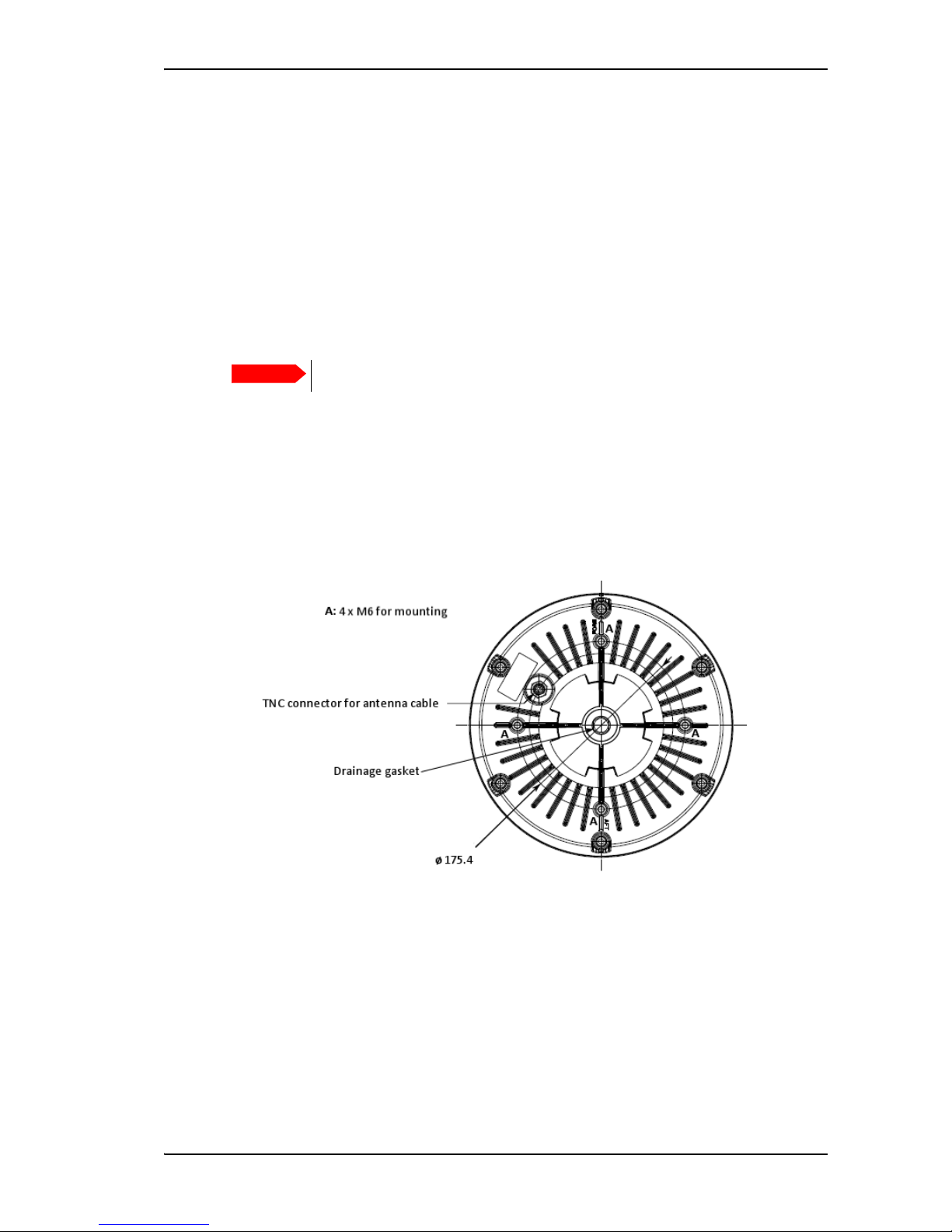
Custom mast mounting:
For a custom mast mounting, use 4 M6 bolts (A4) in the threaded bushings on the 175.4 mm
diameter circle in the bottom of the antenna. The length of the bolts must be such that they
engage into the bushings of the radome with min. 6 mm and max. 12 mm.
Drill a hole for the cable in the mast flange or use an angled connector.
Mast length and diameter
The placement of the antenna must ensure a rigid structural connection to the hull or structure
of the ship. Parts of the ship with heavy resonant vibrations are not suitable places for the
antenna.
A small platform or short mast provides rigid support for the antenna fastening bolts and a rigid
interface to the ship.
If it is necessary to use a tall mast, use the table on page 12 to obtain the maximum free length
of the mast. Note that these values depend on rigid antenna-ship interfaces. The crosssectional properties and the corresponding maximum free length give a natural frequency
above 30 Hz.
It is recommended to shorten the mast length as much as possible to obtain higher
frequencies. Alternatively, mount stays or wires to stabilize the mast further.
High masts or installations on ships with high vibration levels should be further stabilized by
stays or wires from the mast flange. Also mount vibration isolators between the flange and the
radome. For SAILOR Fleet One, the vibration isolators are included in the Mast mount kit.
Important
Do not block the drainage hole in the centre bottom of the antenna.
Note
The table in the next section lists the values for steel masts.
For aluminium masts, the free mast length is reduced to 75% of the values for steel.
Chapter 2: Installation
98-141368-A 12
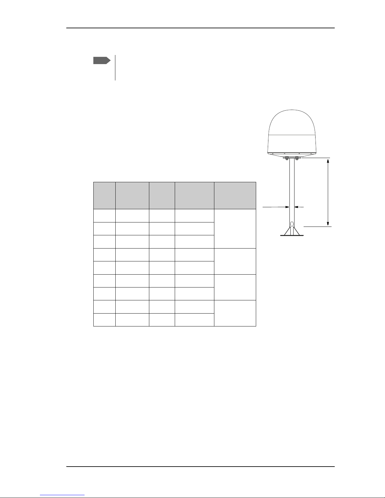
Antenna mast length
The below table shows the values for a SAILOR Fleet One
antenna mast without stays or wires. Note that these values
are only guidelines - always consider the environment and
characteristics of the ship before deciding on the mast
dimensions.
The mast mount kit interfaces to a 1½” tube (OD 48.3 mm absolute maximum OD 52 mm). Masts with larger diameters
must be tapered and the upper part of the tube (approximately
50 mm) must have a diameter of 1½”.
Note
Stays and rigid masts can still not prevent vertical vibration if the mast is attached to a
deck plate that is not rigid. Make every effort to mount the mast on a surface that is
well supported by ribs. If this is not possible, provide extra deck plate propping.
OD
(mm)
Wall
Thickness
(mm)
Weight
(kg/m)
Inertia
(X10
6
mm4)
Max. free
mast length
(steel), m
48.3 3.25 3.61 0.117
< 0.6
48.3 4.05 4.43 0.139
50 3.00 3.48 0.123
60.3 3.65 5.10 0.262
<0.8
60.3 4.50 6.17 0.309
76.1 3.65 6.80 0.547
< 1.0
76.1 4.50 7.90 0.651
88.9 4.05 8.47 0.974
< 1.1
88.9 4.85 10.10 1.140
Free mast length (m)
OD (mm)
Chapter 2: Installation
98-141368-A 13
Install the antenna
Ground the antenna
You may ground the antenna using the mounting bolts.
If the antenna cannot or should not be electrically connected directly to the mounting surface,
you can use a separate grounding cable to make the connection between the antenna and the
common ground to which the terminal is also connected. For example, you can connect a
separate grounding cable when vibration isolators are used at the mounting bolts.
To obtain a good ground connection, the metal underneath the head of at least one bolt must
be clean of insulating protective coating and a serrated washer should be used. After tightening
the bolts we recommend that you seal the area suitably in order to avoid corrosion of the
grounding point.
Use stainless steel bolts and washers.
Antenna cables
Guidelines
A coaxial cable for connection between the antenna and terminal is delivered with the system.
If you need a different cable, make sure that the cable meets the requirements. Preferably
choose one of the cable types in Recommended antenna cables below.
Select a suitable area for installation of the terminal, antenna and cradle. Where the cables are
exposed to mechanical wear - on deck, through bulkheads, etc. - protect the cables with steel
pipes. Otherwise, follow standard procedures for cabling in ship installations.
The maximum allowed RF-loss in the antenna cable is 20 dB at 1660 MHz. This is to ensure the
performance of the system.
Recommended antenna cables
The table below shows recommended cable types and maximum cable lengths for
SAILOR Fleet One.
Check in the data sheet from the cable supplier that both the RF- attenuation and the DCresistance are kept within the maximum specified values:
• Antenna cable RF-attenuation at 1660 MHz: max. 20 dB incl. connector.
Cable Type
Absolute maximum
length
G02232-D 6 m
RG223-D 25 m
RG214/U 50 m
S 07272B-05 95 m

Chapter 2: Installation
98-141368-A 14
• Antenna cable modem-attenuation at 54 MHz: max. 4 dB.
Antenna cable modem-attenuation at 36 MHz: max. 3 dB.
• Antenna cable loop DC-resistance max: 1 Ohm.
Also ensure that the specified minimum bending radius is respected. If this is not the case, the
loss in the cable will increase. Check the instructions from the cable supplier.
Important mounting notes
Water intrusion
After having connected the antenna cable to the antenna, ensure that the connector assembly
is properly protected against seawater and corrosion. As a minimum, use self-amalgamating
rubber.
If possible, install the radome such that direct spray of sea water is avoided.
It is recommended not to use pneumatic tools for cleaning the radome, especially at a short
distance and directly at the split between top and bottom.
Note that the SAILOR Fleet One antenna is drained for condensation through the gasket in the
bottom centre. Make sure the requirements to drainage are met. See the next section
Condensation.
Condensation
In some cases there will be condensation inside the radome. The gasket in the bottom centre
of the SAILOR Fleet One antenna is designed to lead any water away from the radome. Make
sure the drainage gasket is not blocked when you mount the antenna.
Drainage gasket
Chapter 2: Installation
98-141368-A 15
Mount the antenna
The radome can now be installed on the ship with 4 stainless steel bolts fastened to the hull or
to a mast.
For information on mast mounting, see Antenna mast design on page 11.
To mount the antenna on the hull
Make sure the antenna has line of sight to the satellites. When the antenna is mounted directly
on the hull, it may be difficult to obtain line of sight, especially down to -60°, which is the
maximum rotation angle (pitch and roll) for the SAILOR Fleet One antenna.
Make sure to leave room for the connector and cable under the antenna.
Mount the antenna with 4 M6 bolts into the threaded bushings in the bottom of the antenna
(marked A in the drawing below).
The bolt thread must not penetrate more than 12 mm (or 8 turns of the bolt) - and not less
than 6 mm (or 4 turns of the bolt)- into the threaded part of the bushings in the radome.
Fasten the bolts with 7-8 Nm torque.
Important
Do not block the drainage hole in the centre bottom of the antenna.
Chapter 2: Installation
98-141368-A 16
Mounting considerations for the terminal
Where to place the terminal
Temperature conditions
The terminal must be placed in a ventilated area with free space around all sides of the unit,
except the bottom side.
Ambient temperature range is –25 °C to +55 °C.
If the terminal is installed in a location where the ambient temperature may exceed 45 °C, we
recommend placing the terminal where unintentional contact is avoided. If the maximum
ambient temperature does not exceed 45 °C, the terminal can be placed in a public area.
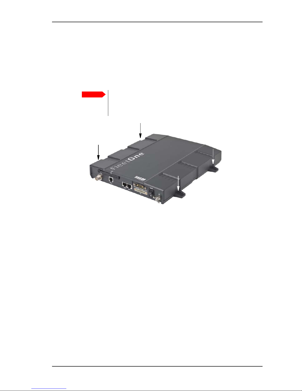
Grounding access
The terminal is designed with a case for bulkhead or desktop installation. The case is equipped
with mounting brackets, making it possible to secure the unit on a bulkhead.
Important
The terminal must be placed in an area where access to the hull or equivalent
grounding can be reached within 0.5 m.
Chapter 2: Installation
98-141368-A 17
Install the terminal
Ground the terminal
Antenna cable
The antenna ground is connected to the terminal ground by means of the coax cable with a
TNC connector at both ends.
For information on antenna grounding, see Ground the antenna on page 13.
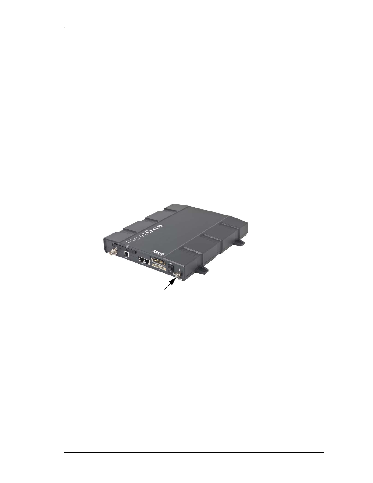
Ground stud
To ensure that the terminal is grounded – also if the cable is disconnected from the terminal,
connect an extra ground wire to the ground stud on the terminal. This ground wire must be a
heavy wire or braid cable with a larger diameter than the coax cable. The ground stud is located
next to the power switch.
Ground stud
Chapter 2: Installation
98-141368-A 18
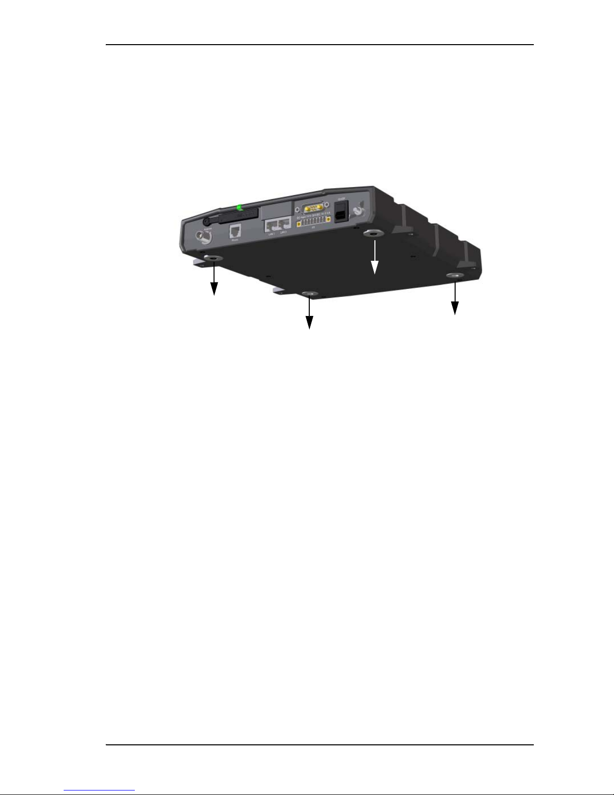
Ground connection through the mounting surface
In addition to the ground stud you may connect the terminal chassis to ground through the
mounting surface. Make sure you have a good electrical connection between the terminal
chassis and the mounting surface.
1. Remove the four rubber feet from the terminal.
2. Attach the terminal to the mounting surface using four screws through the mounting
surface and into the threaded bushings on the underneath of the terminal.
Chapter 2: Installation
98-141368-A 19
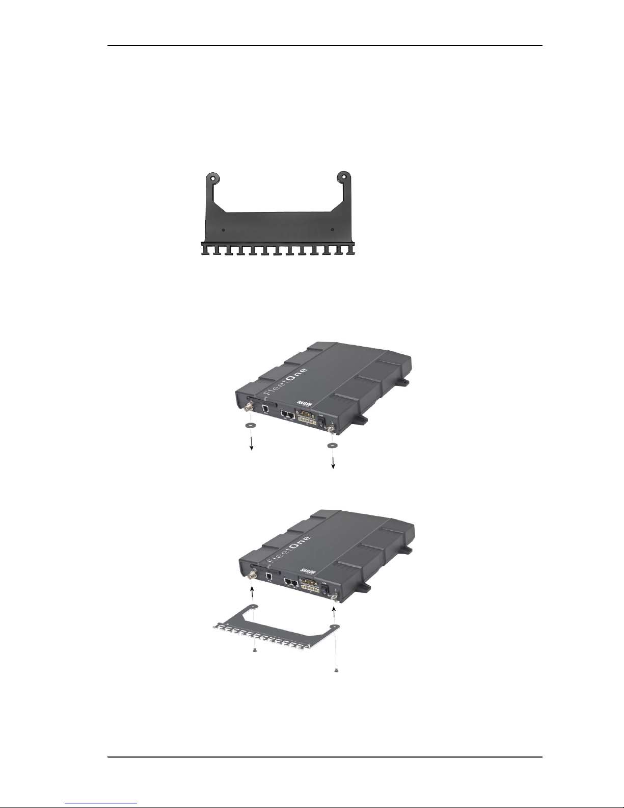
Mount the Basic cable support (optional)
If you want to use a cable support for your terminal, you can acquire a Basic cable support
(“Accessories kit F/ Terminal”, spare part no. S-673738A) from your distributor.
When mounted on the terminal the Basic cable support offers a number of holders to which
you can secure the cables from the terminal, using cable strips.
To mount the Basic cable support, do as follows:
1. Remove the two rubber washers from the bottom of the terminal at the connector panel
end. The threaded bushings underneath the rubber washers are used for mounting the
cable support.
2. Fasten the Basic cable support to the terminal using two M4 x 6 mm countersunk screws.
3. Install the terminal as described in To install the terminal on a bulkhead on page 20 or To
install the terminal on a desktop on page 20.
Chapter 2: Installation
98-141368-A 20
To install the terminal on a bulkhead
Terminal with no cable support
Do as follows to mount the terminal on a bulkhead:
1. Insert four screws through the mounting holes and into the mounting surface.
2. Connect all cables.
Terminal with Basic cable support
First mount the Basic cable support on the terminal as described in Mount the Basic cable
support (optional) on page 19.
1. Mount the terminal with the Basic cable support on the bulkhead by inserting four screws
through the holes in the mounting bracket and into the mounting surface.
2. Connect all cables.
3. Secure the cables to the cable support using cable strips.
To install the terminal on a desktop
Four rubber feet make the terminal well suited for desktop installation. Simply place the
terminal on a desktop and connect all cables.
If required, fasten the terminal to the desktop with four screws, as described in the previous
section To install the terminal on a bulkhead.
Make sure that the grounding requirements are met. See Ground the terminal on page 17.
Important
This mounting method cannot be used for grounding. If you are using the
mounting surface for grounding, you must use the threaded bushings on the
underneath of the terminal instead. See Ground connection through the
mounting surface on page 18.
Chapter 2: Installation
98-141368-A 21
Connect cables
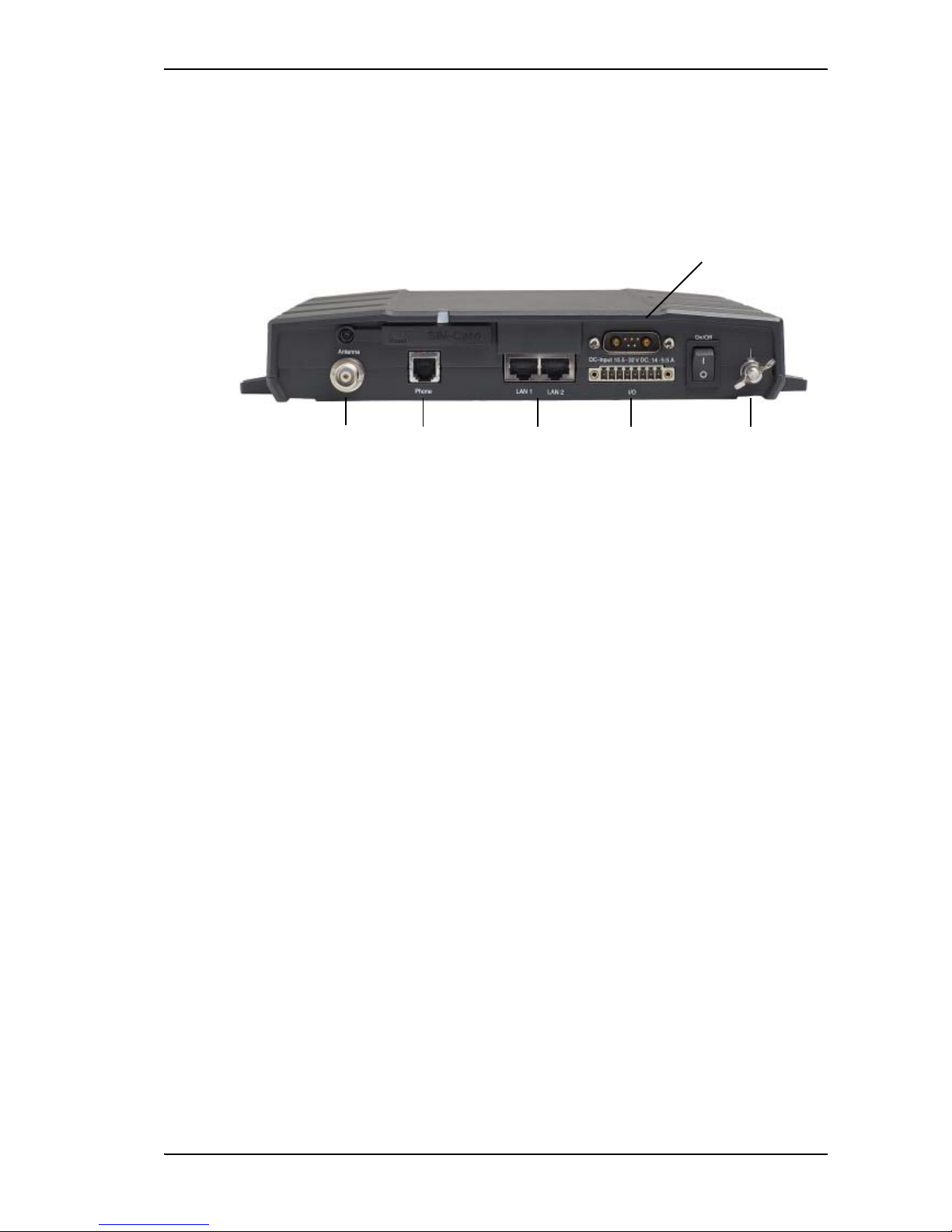
The connector panel
The connector panel has the following connectors:
• 1 Antenna connector (TNC)
• 1 Phone connector
• 2 LAN connectors with Power over Ethernet (PoE)
• 1 DC power input connector for connection to 10.5-32 V DC, with optional remote on/off
• 1 Input/Output connector with 5 inputs/outputs for external control or signalling
• 1 ground stud with wing nut
For information on how to connect to a specific interface, see the next sections.
DC power input
Phone 2 x LAN I/O GroundAntenna
Chapter 2: Installation
98-141368-A 22
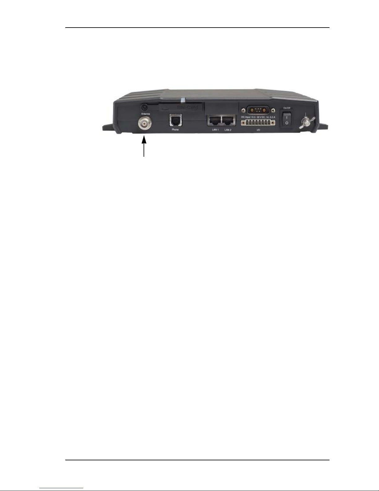
Antenna interface on the terminal
The antenna interface on the terminal connects to the SAILOR Fleet One antenna. The
connector on the terminal is a TNC female connector. An antenna cable (10 m) is included in
the delivery.
To connect the antenna to the terminal
1. Connect the antenna cable between the Antenna connector on the terminal and the
connector on the underneath of the antenna.
2. Where the cables are exposed to mechanical wear - on deck, through bulkheads, etc. protect the cables with steel pipes. Otherwise, follow standard procedures for cabling in
ship installations.
For information on alternative cables and how to install and connect the antenna, see Install
the antenna on page 13.
DC power input
The DC power input for the terminal is a 10.5 - 32 V DC; 11.5 A - 4 A input with a remote on/off
function. The input is protected against reverse polarity.
There are different options for the power supply:
• The 24 V DC ship supply provides power for the terminal.
• A 12 V DC supply provides power for the terminal. Note that the maximum allowed source
impedance is much lower for a 12 V DC supply than for a 24 V DC supply. Also, the total
output power available for Power over Ethernet is limited when the power supply is 12 V
DC.
• A 230 V AC supply provides power through an AC/DC power supply.
Be aware of high start-up peak current: 20 A at 24 V, 5 ms.
The terminal is equipped with an internal 20 A Fuse, so no external fuse is necessary in order to
protect the terminal. However, in order to avoid short circuit in the power cable/connector, the
ship’s DC outlet should be protected by a 30 A fuse or circuit breaker.
 Loading...