

COBHAM Sailor 900 VSAT Installation Manual
SAILOR 900 VSAT
Installation manual
Installation manual for item number 407090B

SAILOR 900 VSAT
Quick guide
Introduction
This quick guide aims at experienced service personnel who have installed the SAILOR 900 VSAT system
and connected power. It lists the minimum configuration tasks you have to make before the system. can
be used on-air on a satellite.
Prerequisites
1. Connect a PC to the front LAN connector or the LAN3 connector at the rear of the Antenna Control
Unit.
2. Open an Internet Browser and type the default IP address of the SAILOR 900 VSAT: http://192.168.0.1
to access the web interface.
Configuration tasks (minimum)
Configuration task What to do and where to find more information
Heading input
Azimuth calibration
TX cable calibration
VSAT modem connection
Modem profile
Network settings
Configure the heading input to External under SERVICE > Calibration.
For more information see Select the desired heading input, see table
below. on page 6-6.
Connect the ship’s heading (RS-422, NMEA0183) to the NMEA 0183 multiconnector. Pin 8 Ship Ground/Shield (connect only one end), Pin 9 Line B +,
and Pin 10 Line A-. For more information see NMEA 0183 connector on
page 4-4.
Make an azimuth calibration under SERVICE > Calibration to ensure that
the SAILOR VSAT can point and receive satellite signal. For more
information see Azimuth calibration on page 6-8.
Make a Tx cable calibration under SERVICE > Calibration to ensure that
Tx power is calibrated at all frequencies. For more information see Cable
calibration on page 6-10.
See Appendix E or http://www.lyngsat.com for DVB-S transponder
information.
Connect cables between the modem and the ACU. For more information
see VMU settings on page C-1.
Configure the modem profile under SETTINGS > Satellite profiles >
VSAT modem profiles. For more information see VSAT modem profile –
New entry and Edit on page 6-25.
Configure the network settings under SETTINGS > Network if the
modem communicates with IP to the ACU. For more information see To
configure the LAN network on page 6-29.
Satellite profile
You find a flow chart for the calibration procedure on page 6-12.
98-138976-C
Configure the satellite profile under SETTINGS > Satellite profiles and
then activate the satellite profile and wait for the system to acquire the
satellite and start tracking. For more information see Satellite profiles –
New entry and Edit on page 6-23 and Satellite profiles on page 6-22.


SAILOR 900 VSAT
Installation manual
Document number: 98-138976-C
Release date: 20 February 2014

Disclaimer
Any responsibility or liability for loss or damage in connection with the use of this product and the
accompanying documentation is disclaimed by Thrane & Thrane A/S. The information in this manual is
provided for information purposes only, is subject to change without notice and may contain errors or
inaccuracies. Manuals issued by Thrane & Thrane A/S are periodically revised and updated. Anyone
relying on this information should acquire the most current version e.g. from www.cobham.com/satcom
or from the distributor. Thrane & Thrane A/S is not responsible for the content or accuracy of any
translations or reproductions, in whole or in part, of this manual from any other source.
Thrane & Thrane A/S is trading as Cobham SATCOM.
Copyright
© 2014 Thrane & Thrane A/S. All rights reserved.
Trademark acknowledgements
• Thrane & Thrane is a registered trademark of Thrane & Thrane A/S in the European Union and the
United States.
• Inmarsat is a registered trademark of the International Maritime Satellite Organisation (IMSO) and is
licensed by IMSO to Inmarsat Limited and Inmarsat Ventures plc.
• Other product and company names mentioned in this manual may be trademarks or trade names of
their respective owners.
GPL notification
The software included in this product contains copyrighted software that is licensed under the GPL/LGPL.
The verbatim licenses can be found online at:
http://www.gnu.org/licenses/old-licenses/gpl-2.0.html
http://www.gnu.org/licenses/old-licenses/lgpl-2.1.html
You may obtain the complete corresponding source code from us for a period of three years after our last
shipment of this product, which will be no earlier than 2021, by sending a money order or check for DKK
50 to:
SW Technology/GPL Compliance,
Thrane & Thrane A/S,
Lundtoftegaardsvej 93D
2800 Lyngby
DENMARK
Please write "source for product SAILOR 900 VSAT" in the memo line of your payment. This offer is valid
to anyone in receipt of this information.
ii 98-138976-C
Safety summary
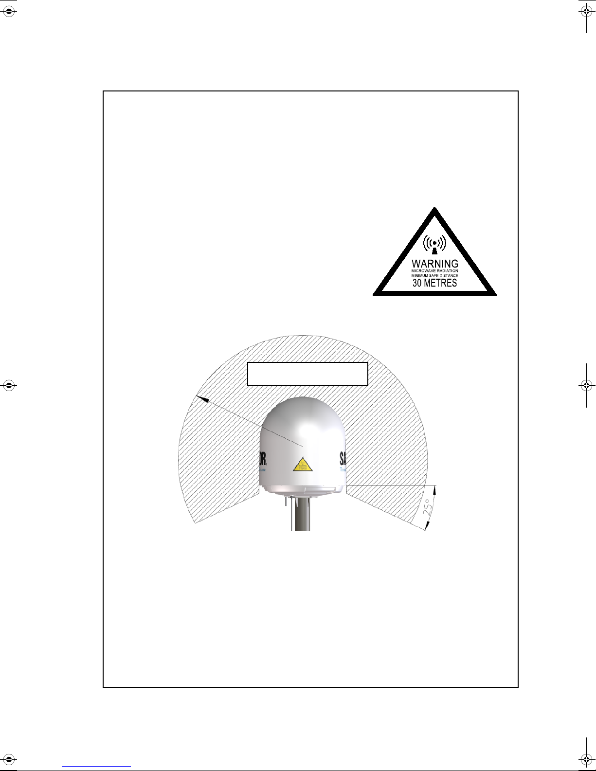
MICROWAVE RADIATION
No personnel within safety distance
Safety distance:
30 m, 10 W/m
2
The following general safety precautions must be observed during all phases of operation,
service and repair of this equipment. Failure to comply with these precautions or with specific
warnings elsewhere in this manual violates safety standards of design, manufacture and
intended use of the equipment. Thrane & Thrane A/S assumes no liability for the customer's
failure to comply with these requirements.
Microwave radiation hazards
During transmission the Above Deck Unit (antenna) in this
system radiates Microwave Power.This radiation may be
hazardous to humans close to the Above Deck Unit. During
transmission, make sure that nobody gets closer than the
recommended minimum safety distance.
The minimum safety distance to the Above Deck Unit
reflector on the focal line is 30 m, based on a radiation level
of 10 W/m
drawing below.
2
. No hazard exists >25° below the Above Deck Unit’s mounting plane. Refer to the
No-transmit zones
In order to protect personnel no-transmit zones can be programmed. For further information
see Blocking zones – azimuth and elevation on page 3-5.
Distance to other equipment
Do not move the Above Deck Unit closer to radars than the minimum safe distance specified in
section Interference on page 3-13 — it may cause damage to the Above Deck Unit.
Compass Safe Distance:
SAILOR 900 VSAT antenna or ADU (Above Deck Unit): min. 170 cm (IEC 60945).
SAILOR 900 VSAT ACU (Antenna Control Unit): min. 10 cm (IEC 60945)
98-138976-C iii
Service
User access to the interior of the ACU is prohibited. Only a technician authorized by Cobham
SATCOM may perform service - failure to comply with this rule will void the warranty. Access to
the interior of the Above Deck Unit is allowed. Replacement of certain modules and general
service may only be performed by a technician authorized by Cobham SATCOM.
Grounding, cables and connections
To minimize shock hazard and to protect against lightning, the equipment chassis and cabinet
must be connected to an electrical ground. The ACU must be grounded to the ship. For further
grounding information refer to the Installation manual.
Do not extend the cables beyond the lengths specified for the equipment. The cable between
the ACU and Above Deck Unit can be extended if it complies with the specified data
concerning cable losses etc.
Rx and Tx cables for the SAILOR 900 VSAT system are shielded and should not be affected by
magnetic fields. However, try to avoid running cables parallel to high power and AC/RF wiring as
it might cause malfunction of the equipment.
Power supply
The voltage range for the SAILOR 900 VSAT is 20 – 32 VDC. Note that the Above Deck Unit is
powered by the ACU.
If a 24 VDC power bus is not available, an external 115/230 VAC to 28 VDC power supply can
be used, for example a SAILOR 6080 Power Supply.
Do not operate in an explosive atmosphere
Do not operate the equipment in the presence of flammable gases or fumes. Operation of any
electrical equipment in such an environment constitutes a definite safety hazard.
Keep away from live circuits
Operating personnel must not remove equipment covers. Component replacement and internal
adjustment must be made by qualified maintenance personnel. Do not replace components
with the power cable connected. Under certain conditions, dangerous voltages may exist even
with the power cable removed. To avoid injuries, always disconnect power and discharge
circuits before touching them.
Failure to comply with the rules above will void the warranty!
iv 98-138976-C
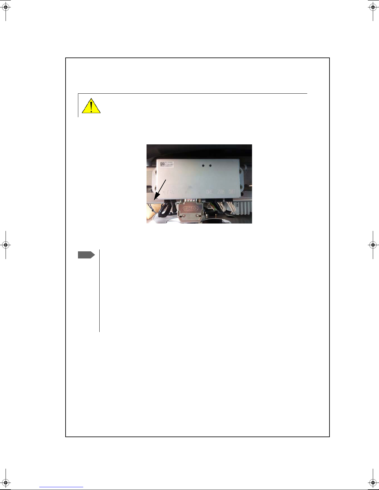
CAUTION! Do not manually turn the Polarisation Unit of the antenna, it
Remove
M
Note
may cause damage to the antenna.
If needed to turn the Polarisation Unit manually, remove the connector (1) marked M of the
Polarisation Motor Module (2).
VSAT restrictions
There are restrictions in use of the frequency band 13.75 to 14 GHz in the
following countries:
•Belgium
•Hungary
•Latvia
•Malta
•Slovakia
Contact the VSAT modem provider for local setups.
98-138976-C v
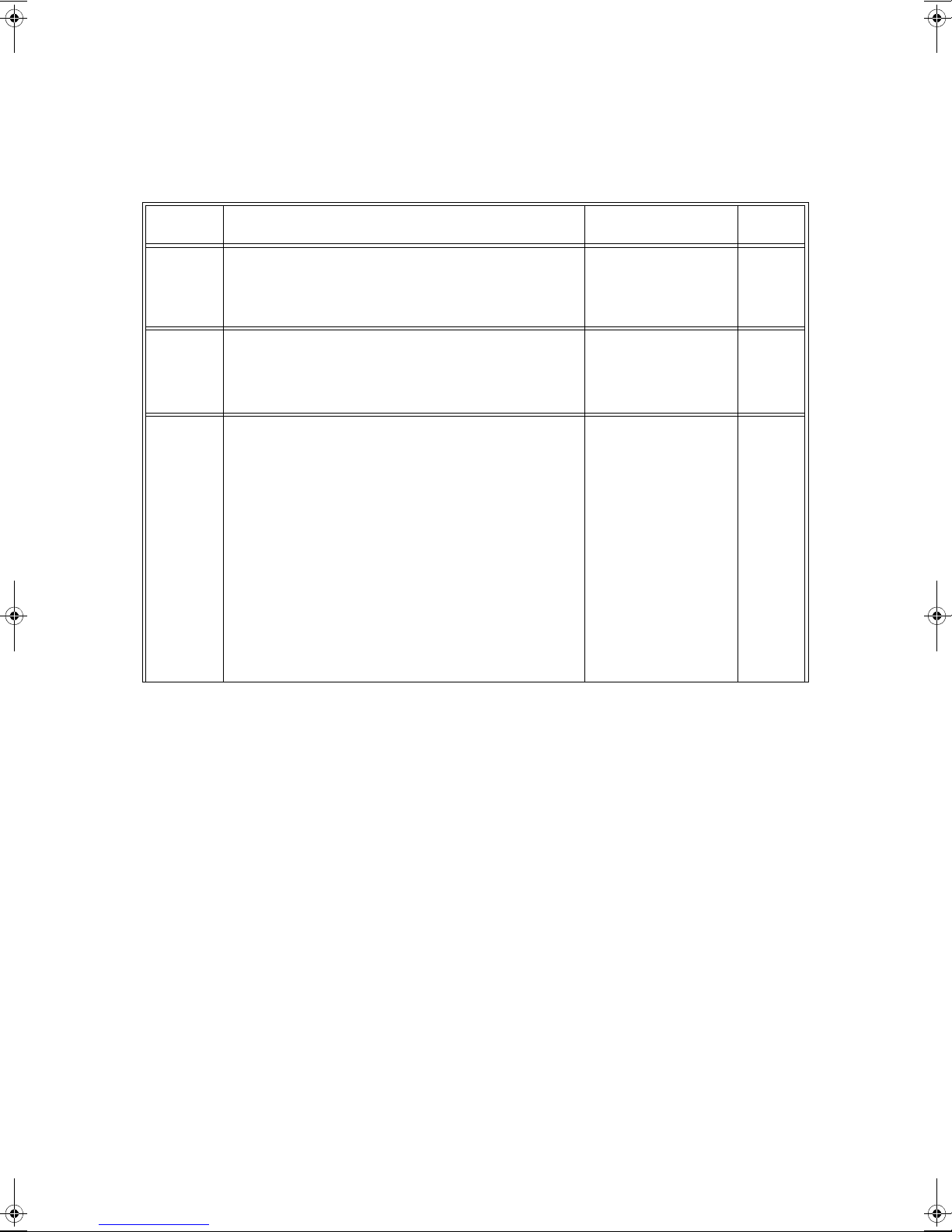
Record of Revisions
Rev. Description Release Date Initials
A Original document 23 April 2013 UFO
B The following sections have been edited: 2.1.1, 3.2.6,
3.3, A.1.2.
The following section has been added: H.3
C The following sections have been added: 8.6.4, 8.6.5,
C.1, C.4, H4, H.5
The following sections have been edited: 1.3, 2.1,
3.3.1, 3.3.4, 4.1.7, 4.2, 6.2, 6.3.1, 6.5, C.2.1, C.3.1, G.2,
G.3
The following figures have been added: 6-42, 6-5, 6-6,
6-7
The following figures have been edited: 6-4, 6-6, 6-14,
The following tables have been added: 6-2, 6-3
The following tables have been edited: 4-4, 6-12, A-2,
A-3, C-1,
02 May 2013 UFO
20 February 2014 UFO
vi 98-138976-C

Table of Contents
Chapter 1 About this manual
1.1 Intended readers ..............................................................................................................1-1
1.2 Manual overview ...............................................................................................................1-1
1.3 Software version ...............................................................................................................1-1
1.4 Typography ...........................................................................................................................1-2
1.5 Precautions ............................................................................................................................1-2
1.5.1 Warnings, Cautions and Notes .....................................................................................1-2
1.5.2 General precautions ...........................................................................................................1-2
Chapter 2 Introduction
2.1 SAILOR 900 VSAT system .........................................................................................2-1
2.1.1 Above Deck Unit (ADU) ...................................................................................................2-2
2.1.2 Antenna Control Unit (ACU) ..........................................................................................2-5
2.1.3 VSAT Modem Unit (VMU) ..............................................................................................2-7
2.1.4 Satellite type approvals ....................................................................................................2-7
2.1.5 Power supply (optional) ...................................................................................................2-7
2.1.6 Service activation ................................................................................................................2-7
2.2 Part numbers and options .........................................................................................2-8
2.2.1 Applicable Thrane & Thrane model and part numbers .....................................2-8
2.2.2 Options for SAILOR 900 VSAT .....................................................................................2-8
Chapter 3 Installation
3.1 Unpacking ...............................................................................................................................3-1
3.1.1 What’s in the box ................................................................................................................3-1
3.1.2 Initial inspection ..................................................................................................................3-2
3.1.3 Tools needed .........................................................................................................................3-2
3.2 Site preparation .................................................................................................................3-3
3.2.1 General site considerations ............................................................................................3-3
3.2.2 Obstructions (ADU shadowing) ....................................................................................3-4
3.2.3 Blocking zones – azimuth and elevation .................................................................3-5
3.2.4 Safe access to the ADU: Radiation hazard ..............................................................3-6
3.2.5 Ship motion and offset from the ship’s motion centre ....................................3-7
3.2.6 ADU mast design: Foundation and height ..............................................................3-8
3.2.7 Interference ........................................................................................................................3-13
3.2.8 Other precautions ............................................................................................................3-17
98-138976-C vii

Table of Contents
3.3 Installation of the ADU ............................................................................................3-18
3.3.1 To install the ADU ............................................................................................................3-19
3.3.2 To open and remove the service hatch ................................................................3-22
3.3.3 To ground the ADU .........................................................................................................3-23
3.3.4 Alternative ADU cable ...................................................................................................3-24
3.4 Installation of the ACU ............................................................................................3-25
3.4.1 To install the ACU ............................................................................................................3-25
3.4.2 To ground the ACU .........................................................................................................3-26
3.5 Installation of the VMU ...........................................................................................3-26
3.5.1 General mounting considerations — VMU .........................................................3-26
3.6 To install the dual-antenna mode (optional) ........................................... 3-27
Chapter 4 Interfaces
4.1 Interfaces of the SAILOR 900 VSAT ACU .....................................................4-1
4.1.1 LEDs, display and keypad .................................................................................................4-1
4.1.2 ACU connector panel — overview .............................................................................4-1
4.1.3 DC Input connector ...........................................................................................................4-2
4.1.4 ADU connector ....................................................................................................................4-3
4.1.5 Rx/Tx connectors for VMU ......................................................................................4-3
4.1.6 NMEA 0183 connector ....................................................................................................4-4
4.1.7 RS-232 and RS-422 connectors ...................................................................................4-5
4.1.8 LAN1, LAN2, LAN3 and LAN4 connectors ...............................................................4-6
4.2 Interfaces of the VMU .................................................................................................4-6
Chapter 5 Connecting power
5.1 Power source .......................................................................................................................5-1
5.2 Power cable selection ...................................................................................................5-1
5.2.1 Source impedance ..............................................................................................................5-1
5.2.2 Measuring the ship source impedance .....................................................................5-2
5.2.3 Power cable recommendations ....................................................................................5-2
5.3 Connecting power ............................................................................................................5-3
5.4 Power up .................................................................................................................................5-3
5.4.1 Procedure ................................................................................................................................5-3
5.4.2 Initialisation steps in daily use ......................................................................................5-4
5.4.3 SAILOR 900 VSAT operational .....................................................................................5-4
Chapter 6 Configuration
6.1 Introduction to the built-in web interface ..................................................6-1
6.1.1 Overview ..................................................................................................................................6-1
6.1.2 Connecting to the web interface ................................................................................6-1
viii 98-138976-C

Table of Contents
6.2 Calibration .............................................................................................................................6-3
6.2.1 To set up a service profile for calibration ................................................................6-3
6.2.2 Heading input ........................................................................................................................6-5
6.2.3 Cable calibration ...............................................................................................................6-10
6.2.4 Operation in gyro-free mode .............................................................................6-10
6.2.5 Flow chart for calibration .............................................................................................6-12
6.2.6 To make a line up procedure ......................................................................................6-13
6.2.7 SAILOR 900 VSAT fixed TX gain principle ...........................................................6-15
6.3 Configuration with the web interface ...........................................................6-16
6.3.1 Overview and dashboard ..............................................................................................6-16
6.3.2 Satellite profiles and VSAT modem profiles ....................................................... 6-22
6.3.3 To set up blocking zones (RX and TX) ....................................................................6-27
6.3.4 To configure the LAN network ..................................................................................6-29
6.3.5 E-mail setup ........................................................................................................................6-31
6.3.6 To send statistics reports .............................................................................................6-32
6.3.7 To send a diagnostics report ......................................................................................6-35
6.3.8 Dual antenna mode (optional) ...................................................................................6-36
6.3.9 Upload ...................................................................................................................................6-40
6.3.10 Administration ...................................................................................................................6-40
6.4 Keypad and menus of the ACU ..........................................................................6-46
6.4.1 ACU display and keypad ...............................................................................................6-46
6.4.2 Navigating the menus ....................................................................................................6-47
6.4.3 The menu tree ...................................................................................................................6-47
6.4.4 Adjusting brightness of the display .........................................................................6-51
6.4.5 Resetting the system ......................................................................................................6-51
6.5 SNMP support ..................................................................................................................6-52
Chapter 7 Installation check
7.1 Installation check list: Antenna ............................................................................7-1
7.2 Installation check list: ACU, connectors and wiring .............................7-3
7.3 Installation check list: Functional test in harbor ....................................7-5
Chapter 8 Service
8.1 Getting support: Helpdesk .........................................................................................8-1
8.1.1 Help desk and diagnostic report ..................................................................................8-1
8.2 Software update ................................................................................................................8-3
8.2.1 Hardware and software requirements .......................................................................8-3
8.2.2 Software update (ADU and ACU) ................................................................................8-3
8.2.3 To verify the software update ......................................................................................8-6
98-138976-C ix

Table of Contents
8.3 Status signalling with LEDs and status messages ...................................8-7
8.3.1 LEDs of the ADU modules ...............................................................................................8-7
8.3.2 LEDs in the ACU ...................................................................................................................8-8
8.4 Removal and replacement of the ACU ............................................................8-9
8.5 Removal and replacement of ADU modules ............................................8-10
8.6 Troubleshooting .............................................................................................................8-13
8.6.1 Overview ...............................................................................................................................8-13
8.6.2 Event list for troubleshooting ....................................................................................8-13
8.6.3 Diagnostics report for troubleshooting .................................................................8-13
8.6.4 To verify that the VSAT antenna can go into tracking mode .................... 8-13
8.6.5 X-elevation bearing test ................................................................................................8-14
8.7 Returning units for repair ........................................................................................8-14
Appendix A Technical specifications
A.1 SAILOR 900 VSAT system components .........................................................A-1
A.1.1 General specifications .......................................................................................................A-1
A.1.2 ADU ...........................................................................................................................................A-1
A.1.3 ACU ............................................................................................................................................A-3
A.1.4 Supported VSAT modems ..............................................................................................A-4
A.1.5 Patents ......................................................................................................................................A-4
A.2 Outline drawings ...............................................................................................................A-5
A.2.1 ADU ...........................................................................................................................................A-5
A.2.2 ACU ............................................................................................................................................A-6
A.2.3 N-connector interface on the ADU ............................................................................A-7
A.3 VSAT LNB Data Sheet (physical LNB) ...............................................................A-8
A.3.1 VSAT LNB user installation and configuration information ...........................A-9
A.4 VSAT 8 W BUC Data Sheet (Extended) .....................................................A-10
Appendix B VMU cables
B.1 Modem Cable COMTECH Serial & RSSI TT7016A ...................................B-2
B.2 Modem Cable iNFINITI iDirect VSAT modem ..........................................B-3
Appendix C VMU settings
C.1 Performance optimization for blockage .........................................................C-1
C.1.1 Performance of VSAT systems encountering blockage, configured with
multiple satellites. C-1
C.2 OpenAMIP setup for iDirect iNFINITI & Evolution ..............................C-3
C.2.1 Protocol and interfaces ....................................................................................................C-3
C.2.2 Sample options file .............................................................................................................C-6
C.2.3 Configuration example (OpenAMIP) .........................................................................C-9
C.2.4 Troubleshooting ...............................................................................................................C-10
x 98-138976-C

Table of Contents
C.3 Serial setup for iDirect iNFINITI & Evolution ........................................C-13
C.3.1 Protocol and interfaces .................................................................................................C-13
C.3.2 Console port settings .....................................................................................................C-13
C.3.3 Configuration example (Serial) ..................................................................................C-15
C.4 COMTECH 570L and ROSS box ...........................................................................C-17
C.4.1 Protocols and interfaces ...............................................................................................C-17
C.4.2 Configuration example (COMTECH 570L and ROSS) .....................................C-18
C.5 COMTECH 570L ...............................................................................................................C-19
C.5.1 Protocol and interfaces .................................................................................................C-19
C.5.2 Configuration example (COMTECH 570L) ...........................................................C-21
C.6 STM SatLink 2900 VSAT modem .......................................................................C-22
C.6.1 Interfaces and VSAT modem configuration .......................................................C-22
C.6.2 ACU configuration ...........................................................................................................C-23
C.6.3 Configuration example (STM Satlink 2900) .......................................................C-24
C.7 Gilat SkyEdge II VSAT modem ...........................................................................C-25
C.7.1 Interfaces and VSAT modem configuration .......................................................C-25
C.7.2 ACU configuration ...........................................................................................................C-26
C.7.3 Configuration example (Gilat SkyEdge II) ............................................................C-27
C.8 Inmarsat G5 modem ...................................................................................................C-28
C.8.1 Interfaces and VSAT modem configuration .......................................................C-28
C.8.2 Connecting a Inmarsat G5 modem .........................................................................C-28
C.8.3 Configuration example (Inmarsat G5) ...................................................................C-28
Appendix D Command line interface
D.1 Introduction ........................................................................................................................ D-1
D.1.1 Telnet connection ............................................................................................................. D-1
D.1.2 Help ...........................................................................................................................................D-2
D.1.3 Conventions .........................................................................................................................D-2
D.2 Supported commands ................................................................................................D-3
D.2.1 config .......................................................................................................................................D-3
D.2.2 demo ........................................................................................................................................D-3
D.2.3 dual_antenna ....................................................................................................................... D-4
D.2.4 exit ............................................................................................................................................ D-4
D.2.5 help ...........................................................................................................................................D-4
D.2.6 modem .................................................................................................................................... D-5
D.2.7 satellite ....................................................................................................................................D-5
D.2.8 status ........................................................................................................................................D-7
D.2.9 system .....................................................................................................................................D-8
D.2.10 track .......................................................................................................................................... D-8
D.2.11 zone .......................................................................................................................................... D-9
Appendix E DVB-S satellites
98-138976-C xi

Table of Contents
Appendix F Grounding and RF protection
F.1 Why is grounding required? ......................................................................................F-1
F.1.1 Reasons for grounding ...................................................................................................... F-1
F.1.2 Safety ........................................................................................................................................F-1
F.1.3 ESD Protection .....................................................................................................................F-1
F.2 Grounding Recommendations ................................................................................F-2
F.2.1 To ground the ACU ............................................................................................................F-2
F.2.2 To ground the ADU ............................................................................................................F-2
F.3 Alternative grounding for steel hulls ................................................................ F-3
F.3.1 To ground the ACU ............................................................................................................F-3
F.3.2 To ground the ADU ............................................................................................................F-4
F.4 Alternative grounding for aluminum hulls ....................................................F-5
F.4.1 To ground the ACU ............................................................................................................F-5
F.4.2 To ground the ADU ............................................................................................................F-5
F.5 Alternative grounding for fibre glass hulls ...................................................F-6
F.5.1 To ground the ACU ............................................................................................................F-6
F.5.2 To ground the ADU ............................................................................................................F-6
F.6 Separate ground cable ..................................................................................................F-7
F.6.1 Ground cable - construction ..........................................................................................F-7
F.6.2 Ground cable - connection ............................................................................................. F-8
F.6.3 Isolation of the ADU from the mounting base ..................................................... F-8
F.7 Jumper cable for grounding ...................................................................................F-10
F.8 RF interference ................................................................................................................ F-11
F.8.1 Recommendations .......................................................................................................... F-11
Appendix G System messages
G.1 Event messages – overview ......................................................................................G-1
G.2 List of ADU events ...........................................................................................................G-2
G.3 List of ACU events ...........................................................................................................G-8
Appendix H Approvals
H.1 Overview ................................................................................................................................. H-1
H.2 CE (R&TTE) ............................................................................................................................ H-1
H.3 Eutelsat S.A – ESV Summary Sheet ................................................................... H-3
H.4 Russian Maritime Register of Shipping ........................................................... H-4
H.5 ANATEL Certificado de Homologação ............................................................ H-7
Glossary ..............................................................................................................................................................Glossary-1
Index ....................................................................................................................................................................Index-1
xii 98-138976-C

List of Figures
Chapter 1 About this manual
Chapter 2 Introduction
Figure 2-1: Above Deck Unit and Antenna Control Unit (ACU)..........................................................................2-1
Figure 2-2: Above Deck Unit (ADU) .................................................................................................................................2-2
Figure 2-3: SAILOR 900: Above Deck Unit modules 1/2........................................................................................2-3
Figure 2-4: SAILOR 900: Above Deck Unit modules 2/2........................................................................................2-4
Figure 2-5: SAILOR 900 VSAT ACU, connector overview .....................................................................................2-6
Figure 2-6: SAILOR 900 VSAT ACU, 19” rack version..............................................................................................2-6
Figure 2-7: Antenna Control Unit for 19” rack installation ...................................................................................2-7
Chapter 3 Installation
Figure 3-1: Signal degradation because of obstructing objects .........................................................................3-4
Figure 3-2: 2 blocking zones with no-transmit zones, azimuth (example)....................................................3-5
Figure 3-3: Blocking zone with no-transmit zones, elevation angle (example)...........................................3-5
Figure 3-4: SAILOR 900: Radiation hazard, safety distance 30 m .....................................................................3-6
Figure 3-5: Maximum distance from the ship’s motion centre (h max).........................................................3-7
Figure 3-6: SAILOR 900: ADU mast flange, top and side view ............................................................................3-8
Figure 3-7: ADU mast flange, recommended flatness on the mast mount plateau..................................3-8
Figure 3-8: ADU mast flange, distance to the welded seam.................................................................................3-9
Figure 3-9: SAILOR 900: ADU, bottom view ................................................................................................................3-9
Figure 3-10: Free mast length and bracing for a tall mast.....................................................................................3-10
Figure 3-11: Interference with the vessel’s radar ......................................................................................................3-13
Figure 3-12: Recommended distance to transmitters (m) for frequencies below 1000 MHz.............3-16
Figure 3-13: SAILOR 900: Drain pipe with free space .............................................................................................3-17
Figure 3-14: SAILOR 900: Use of strong sling with a belt and tag lines for safe hoisting...................... 3-18
Figure 3-15: SAILOR 900: Free space for access to the service hatch............................................................3-19
Figure 3-16: SAILOR 900: ADU installation, webbed sling attached to the 4 lifting brackets ............. 3-20
Figure 3-17: Mounting the ADU on the mast flange ...............................................................................................3-20
Figure 3-18: SAILOR 900: Connecting the ADU cable ............................................................................................3-21
Figure 3-19: SAILOR 900: Opening the service hatch .............................................................................................3-22
Figure 3-20: Removing the 2 split pins ...........................................................................................................................3-22
Figure 3-21: SAILOR 900: ADU, bolt for optimum grounding............................................................................. 3-23
Figure 3-22: ACU, On/off switch at the back...............................................................................................................3-25
Figure 3-23: ACU, LAN connector at the front: Service port ............................................................................... 3-25
Figure 3-24: ACU, 19” rack version, ground stud.......................................................................................................3-26
Figure 3-25: Dual mode antenna, overview ................................................................................................................. 3-27
Figure 3-26: Dual mode antenna, connecting cables (example)........................................................................ 3-28
Chapter 4 Interfaces
Figure 4-1: ACU — LEDs, display and keypad .............................................................................................................4-1
98-138976-C xiii

List of Figures
Figure 4-2: ACU: LEDs, display and keypad (detailed) .............................................................................................4-1
Figure 4-3: ACU rack version, connector panel overview......................................................................................4-1
Figure 4-4: DC Input connector with power cable....................................................................................................4-2
Figure 4-5: LAN connectors..................................................................................................................................................4-6
Chapter 5 Connecting power
Figure 5-1: Measuring the ship source impedance ...................................................................................................5-2
Figure 5-2: Connecting power to DC Input..................................................................................................................5-3
Figure 5-3: ACU display after first power on (example with LAN ports 1 and 4 used)............................ 5-4
Chapter 6 Configuration
Figure 6-1: LAN connector used for configuring the SAILOR 900 VSAT ....................................................... 6-1
Figure 6-2: SAILOR 900 Dashboard..................................................................................................................................6-2
Figure 6-3: Service profile for calibration ......................................................................................................................6-4
Figure 6-4: Web interface: SERVICE, Calibration .......................................................................................................6-5
Figure 6-5: Acquisition, search pattern...........................................................................................................................6-6
Figure 6-6: Acquisition, search pattern for inclined orbit ......................................................................................6-7
Figure 6-7: Acquisition, search pattern in gyro-free mode...................................................................................6-7
Figure 6-8: Web interface: SERVICE, Calibration, cable attenuator margin...............................................6-10
Figure 6-9: Example for a calibration – step by step............................................................................................. 6-12
Figure 6-10: Web interface: SERVICE, Line up: Ready for activation...............................................................6-13
Figure 6-11: Web interface: SERVICE, Line up: Antenna ready...........................................................................6-14
Figure 6-12: Fixed TX gain principle (SAILOR 900 VSAT) ..................................................................................... 6-15
Figure 6-13: Topics in the web interface (SITE MAP) ............................................................................................. 6-16
Figure 6-14: Web interface: DASHBOARD of SAILOR 900 VSAT ...................................................................... 6-17
Figure 6-15: Web interface: DASHBOARD, TX - BUC output power (example).......................................... 6-22
Figure 6-16: Web interface: SETTINGS - list of satellite profiles (example).................................................6-23
Figure 6-17: Web interface: SETTINGS, Satellite profiles — new entry (example)..................................6-23
Figure 6-18: Web interface: SETTINGS, VSAT modem profiles — list (example).....................................6-25
Figure 6-19: Web interface: SETTINGS, VSAT modem profile – supported modems............................. 6-25
Figure 6-20: Satellite profile for generic modem.......................................................................................................6-26
Figure 6-21: Web interface: SETTINGS, Blocking zones — azimuth and elevation ................................. 6-27
Figure 6-22: Blocking zone, example: 315 - 45 degrees ........................................................................................ 6-28
Figure 6-23: Blocking zone, example: 45 - 315 degrees ........................................................................................ 6-28
Figure 6-24: Web interface: SETTINGS, Network (default settings).................................................................6-29
Figure 6-25: Web interface: SETTINGS, E-mail setup (example) ....................................................................... 6-31
Figure 6-26: Web interface: SETTINGS, Reports (example).................................................................................6-32
Figure 6-27: Statistics — how to read data for a range.........................................................................................6-34
Figure 6-28: Statistics report (example).........................................................................................................................6-35
Figure 6-29: Dual-antenna mode, link on DASHBOARD......................................................................................... 6-36
Figure 6-30: Enabling dual-antenna mode in Master ACU....................................................................................6-37
Figure 6-31: Dual-antenna mode, add Slave modem profile...............................................................................6-37
Figure 6-32: Dual-antenna mode, add Slave satellite profile...............................................................................6-38
xiv 98-138976-C

List of Figures
Figure 6-33: Dual-antenna mode, Activate .................................................................................................................. 6-38
Figure 6-34: Dual-antenna mode, blocking zones — azimuth and elevation.............................................. 6-39
Figure 6-35: Dual-antenna mode, line up......................................................................................................................6-40
Figure 6-36: Web interface: Administration.................................................................................................................6-41
Figure 6-37: Web interface: Administration, change administrator logon and password ..................... 6-41
Figure 6-38: Web interface: ADMINISTRATION, Reset administrator password ......................................6-42
Figure 6-39: Web interface: ADMINISTRATION, User permissions ................................................................. 6-43
Figure 6-40: Web interface: Administration, Export/import configuration ..................................................6-44
Figure 6-41: Web interface: ADMINISTRATION, Factory default..................................................................... 6-45
Figure 6-42: Display (example) and keypad of the ACU........................................................................................6-46
Figure 6-43: Antenna Control Unit, menu tree...........................................................................................................6-47
Figure 6-44: Reset the system.............................................................................................................................................6-51
Figure 6-45: Download of MIB file ...................................................................................................................................6-52
Chapter 7 Installation check
Chapter 8 Service
Figure 8-1: Web interface: HELPDESK .............................................................................................................................8-1
Figure 8-2: Web interface: HELPDESK, Event list........................................................................................................8-2
Figure 8-3: LAN connector used for software update (TMA) ..............................................................................8-4
Figure 8-4: SAILOR 900 VSAT connected: Software update with the TMA.................................................8-4
Figure 8-5: LAN connector used for software update (web interface)............................................................8-5
Figure 8-6: Software update with the web interface...............................................................................................8-5
Figure 8-7: Verifying software update, SAILOR 900 VSAT ...................................................................................8-6
Figure 8-8: LEDs on the ACU................................................................................................................................................8-8
Figure 8-9: Removal and replacement of the ACU ...................................................................................................8-9
Figure 8-10: SAILOR 900: ADU modules and motor stop switch ...................................................................... 8-10
Figure 8-11: SAILOR 900: Above Deck Unit modules (continued)....................................................................8-12
Figure 8-12: X-elevation bearing test (service)...........................................................................................................8-14
App. A Technical specifications
Figure A-1: Outline drawing: ADU......................................................................................................................................A-5
Figure A-2: Outline drawing: ACU, 19 inch rack..........................................................................................................A-6
Figure A-3: N-Connector interface on the ADU .........................................................................................................A-7
App. B VMU cables
Figure B-1: Modem Cable COMTECH Serial & RSSI TT7016A...........................................................................B-2
Figure B-2: Modem Cable iNFINITI iDirect VSAT modem...................................................................................B-3
App. C VMU settings
Figure C-1: Connecting iDirect iNFINITI 5000 series to the ACU (OpenAMIP) .........................................C-3
Figure C-2: Connecting iDirect Evolution X5 to the ACU (OpenAMIP)...........................................................C-4
Figure C-3: Supported OpenAMIP commands ............................................................................................................C-5
Figure C-4: VSAT modem profile, OpenAMIP (example) .......................................................................................C-9
98-138976-C xv

List of Figures
Figure C-5: Satellite profile, OpenAMIP (example)....................................................................................................C-9
Figure C-6: iDirect OpenAMIP troubleshooting.......................................................................................................C-11
Figure C-7: Connecting iDirect iNFINITI 5000 series to the ACU (Serial)..................................................C-13
Figure C-8: Connecting iDirect Evolution X5 to the ACU (Serial) ...................................................................C-13
Figure C-9: VSAT modem profile, Serial (example)................................................................................................C-15
Figure C-10: Satellite profile, Serial (example) ............................................................................................................C-16
Figure C-11: Connecting COMTECH 570L and ROSS box to the ACU (example)......................................C-17
Figure C-12: VSAT modem profile, COMTECH 570L and ROSS (example) ...................................................C-18
Figure C-13: Satellite profile, COMTECH 570L and ROSS (example) ...............................................................C-18
Figure C-14: Connecting COMECH 570L to the ACU (example)........................................................................C-20
Figure C-15: VSAT modem profile, COMTECH 570L (example).........................................................................C-21
Figure C-16: Satellite profile, COMTECH 570L (example) .....................................................................................C-21
Figure C-17: Connecting STM SatLink 2900 VSAT modem to the ACU ........................................................C-22
Figure C-18: VSAT modem profile, STM SatLink 2900 (example) ....................................................................C-24
Figure C-19: Satellite profile, STM SatLink 2900 (example).................................................................................C-24
Figure C-20: Connecting Gilat SkyEdge II VSAT modem to the ACU .............................................................C-25
Figure C-21: Connecting Gilat SkyEdge II VSAT modem (rack) to the ACU ................................................C-25
Figure C-22: VSAT modem profile, Gilat Sky Edge II (example).........................................................................C-27
Figure C-23: Satellite profile, Gilat Sky Edge II (example) .....................................................................................C-27
Figure C-24: VSAT modem profile, Inmarsat G5 (example) .................................................................................C-28
Figure C-25: Satellite profile, Inmarsat G5 (example)..............................................................................................C-28
App. D Command line interface
Figure D-1: How to use the command line interface (example for telnet)....................................................D-1
Figure D-2: Command line interface, login....................................................................................................................D-2
App. E DVB-S satellites
Figure E-1: Satellite data, example from www.lyngsat.com................................................................................. E-2
App. F Grounding and RF protection
Figure F-1: Extending the ground plane.........................................................................................................................F-2
Figure F-2: Grounding the ADU.......................................................................................................................................... F-3
Figure F-3: Grounding at a dedicated RF ground (alternative)............................................................................ F-4
Figure F-4: Alternative grounding for aluminium hulls ...........................................................................................F-5
Figure F-5: Alternative grounding for fibreglass hulls.............................................................................................. F-6
Figure F-6: Separate ground cable .................................................................................................................................... F-7
Figure F-7: Isolation of the ADU from the mounting base...................................................................................F-8
Figure F-8: ADU isolation and grounding cable.......................................................................................................... F-9
Figure F-9: Jumper cable for grounding (specifications)......................................................................................F-10
App. G System messages
App. H Approvals
xvi 98-138976-C

List of Tables
Chapter 1 About this manual
Chapter 2 Introduction
Table 2-1: Model and part numbers for the SAILOR 900 VSAT system .......................................................2-8
Table 2-2: Model and part numbers for options of the SAILOR 900 VSAT system ................................ 2-8
Chapter 3 Installation
Table 3-1: Maximum distance from the ship’s motion center versus ship’s roll period.........................3-7
Table 3-2: SAILOR 900: Mast dimensions without braces................................................................................ 3-11
Table 3-3: SAILOR 900: Mast dimensions with 3 braces ...................................................................................3-11
Table 3-4: SAILOR 900: Mast dimensions with 2 braces ...................................................................................3-12
Table 3-5: Minimum radar separation, X-band....................................................................................................... 3-14
Table 3-6: Minimum radar separation, S-band .......................................................................................................3-14
Table 3-7: ADU cable types and maximum lengths.............................................................................................3-24
Table 3-8: Dual mode antenna, cabling...................................................................................................................... 3-28
Chapter 4 Interfaces
Table 4-1: DC Input plug, outline and pin assignment...........................................................................................4-2
Table 4-2: N connector, outline and pin assignment..............................................................................................4-3
Table 4-3: F connector, Rx and Tx, outline and pin assignment.......................................................................4-3
Table 4-4: NMEA 0183/2000 connector, outline and pin assignment.......................................................... 4-4
Table 4-5: RS-232 connector, male, outline and pin assignment.....................................................................4-5
Table 4-6: RS-422 connector, male, outline and pin assignment.....................................................................4-5
Table 4-7: Ethernet connector, outline and pin assignment...............................................................................4-6
Chapter 5 Connecting power
Chapter 6 Configuration
Table 6-1: Satellite requirements for elevation and carrier.................................................................................6-4
Table 6-2: Heading input options.....................................................................................................................................6-6
Table 6-3: SAILOR VSAT acquisition time ...................................................................................................................6-7
Table 6-4: Satellite identifier and NID values.............................................................................................................6-8
Table 6-5: Possible error codes during calibration...................................................................................................6-9
Table 6-6: Satellite elevation and max. allowed inclination............................................................................. 6-11
Table 6-7: Web interface: Event icon..........................................................................................................................6-18
Table 6-8: Web interface, DASHBOARD, SAILOR 900 VSAT parameters..................................................6-20
Table 6-9: Web interface, DASHBOARD, VSAT MODEM parameter...........................................................6-21
Table 6-10: Web interface, DASHBOARD, POINTING parameter .................................................................... 6-21
98-138976-C xvii

List of Tables
Table 6-11: Web interface, DASHBOARD, TX parameter.....................................................................................6-21
Table 6-12: SAILOR 900: Elevation cutoff (in degrees) versus VSAT modem bandwidth and power .624
Table 6-13: Setup of LAN connectors ........................................................................................................................... 6-30
Table 6-14: Statistics report, header record ...............................................................................................................6-33
Table 6-15: Parameters recorded in a statistics report..........................................................................................6-33
Table 6-16: Top-level menus of the ACU ....................................................................................................................6-48
Table 6-17: ANTENNA menu of the ACU ....................................................................................................................6-48
Table 6-18: MODEM menu of the ACU ........................................................................................................................6-49
Table 6-19: NETWORK menu of the ACU....................................................................................................................6-49
Table 6-20: SATELLITE menu of the ACU ................................................................................................................... 6-50
Table 6-21: EVENTS menu of the ACU......................................................................................................................... 6-50
Chapter 7 Installation check
Table 7-1: Installation check list: Antenna ..................................................................................................................7-1
Table 7-2: Installation check list: ACU, connectors and wiring .........................................................................7-3
Table 7-3: Installation check list: Functional test in harbour..............................................................................7-5
Chapter 8 Service
Table 8-1: LEDs of the ADU modules.............................................................................................................................8-7
Table 8-2: LEDs on the ACU................................................................................................................................................8-8
App. A Technical specifications
Table A-1: General specifications.....................................................................................................................................A-1
Table A-2: Technical specifications for the Above Deck Unit............................................................................A-1
Table A-3: Technical specifications for the ACU......................................................................................................A-3
Table A-4: Supported VSAT modems.............................................................................................................................A-4
Table A-5: Patents....................................................................................................................................................................A-4
Table A-6: Technical specifications for VSAT LNB 1/2..........................................................................................A-8
Table A-7: Technical specifications for VSAT LNB 2/2..........................................................................................A-8
Table A-8: 4-band switching............................................................................................................................................A-10
Table A-9: Technical specifications for VSAT 8 W BUC 1/3............................................................................A-10
Table A-10: Technical specifications for VSAT 8 W BUC 2/3............................................................................A-10
Table A-11: Technical specifications for VSAT 8 W BUC 3/3............................................................................A-11
App. B VMU cables
App. C VMU settings
Table C-1: RS-232 Console cable for iDirect VSAT modem................................................................................C-4
Table C-2: Messages sent from the VSAT modem to the ACU (examples).................................................C-5
Table C-3: Messages sent from the ACU to the VSAT modem (examples).................................................C-6
Table C-4: Ranges for signal strength for iDirect OpenAMIP VSAT modem...............................................C-6
xviii 98-138976-C

List of Tables
Table C-5: Information in the VSAT modem option file ......................................................................................C-8
Table C-6: Requirements for VSAT modem option file, Serial ........................................................................C-14
Table C-7: .................................................................................................................................................................................C-20
Table C-8: Configuration of Gilat SkyEdge II VSAT modem............................................................................C-26
App. D Command line interface
Table D-1: Command typography....................................................................................................................................D-2
Table D-2: UCLI command: config ..................................... D-3
Table D-3: UCLI command: demo ....................................... D-3
Table D-4: UCLI command: dual_antenna............................... D-4
Table D-5: UCLI command: exit ....................................... D-4
Table D-6: UCLI command: help ....................................... D-4
Table D-7: UCLI command: modem ...................................... D-5
Table D-8: UCLI command: satellite.................................. D-5
Table D-9: UCLI command: status ..................................... D-7
Table D-10: UCLI command: system..................................... D-8
Table D-11: UCLI command: track...................................... D-8
Table D-12: UCLI command: zone....................................... D-9
App. E DVB-S satellites
Table E-1: Examples of DVB-S satellites for azimuth calibration......................................................................E-1
App. F Grounding and RF protection
App. G System messages
Table G-1: ADU event messages.......................................................................................................................................G-2
Table G-2: ACU event messages.......................................................................................................................................G-8
App. H Approvals
98-138976-C xix

List of Tables
xx 98-138976-C

Chapter 1
About this manual
About this manual 1
1.1 Intended readers
This is an installation manual for the SAILOR 900 VSAT system, intended for installers of
the system and service personnel. Personnel installing or servicing the system must be
properly trained and authorized by Cobham SATCOM. It is important that you observe all
safety requirements listed in the beginning of this manual, and install the system according
to the guidelines in this manual.
1.2 Manual overview
This manual has the following chapters:
• Introduction
• Installation
• Inter faces
• Connecting power
• Configuration
• Installation check
• Service
This manual has the following appendices:
• Technical specifications
• VMU cables
• VMU settings
• Command line interface
• DVB-S satellites
• Grounding and RF protection
• System messages
• Approvals
1.3 Software version
This manual is intended for SAILOR 900 VSAT with software version 1.48.
98-138976-C 1-1
Typography
1.4 Typography
In this manual, typography is used as indicated below:
Bold is used for the following purposes:
• To emphasize words.
Example: “Do not touch the antenna”.
• To indicate what the user should select in the user interface.
Example: “Select SETTINGS > LAN”.
Italic is used to emphasize the paragraph title in cross-references.
Example: “For further information, see Connecting Cables on page...”.
1.5 Precautions
1.5.1 Warnings, Cautions and Notes
Text marked with “Warning”, “Caution”, “Note” or “Important” show the following type of
data:
• Warning: A Warning is an operation or maintenance procedure that, if not obeyed, can
cause injury or death.
• Caution: A Caution is an operation or maintenance procedure that, if not obeyed, can
cause damage to the equipment.
• Note: A Note gives information to help the reader.
• Important: A text marked Important gives information that is important to the user,
e.g. to make the system work properly. This text does not concern damage on
equipment or personal safety.
1.5.2 General precautions
All personnel who operate equipment or do maintenance as specified in this manual must
know and follow the safety precautions. The warnings and cautions that follow apply to all
parts of this manual.
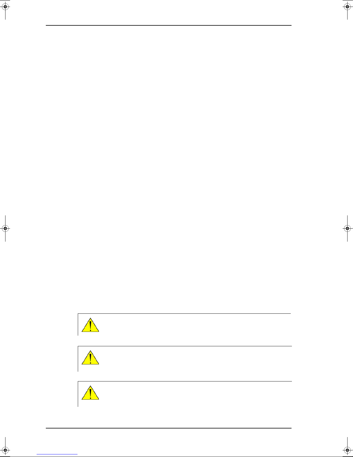
WARNING! Before using any material, refer to the manufacturers’ material
safety data sheets for safety information. Some materials can be dangerous.
CAUTION! Do not use materials that are not equivalent to materials
specified by Thrane & Thrane. Materials that are not equivalent can cause
damage to the equipment.
CAUTION! The system contains items that are electrostatic discharge
sensitive. Use approved industry precautions to keep the risk of damage to a
minimum when you touch, remove or insert parts or assemblies.
1-2 Chapter 1: About this manual 98-138976-C
Chapter 2
Introduction
Above Deck Unit (ADU)
Antenna Control Unit (ACU)
Introduction 2
This chapter is organised in the following sections:
• SAILOR 900 VSAT system
• Part numbers and options
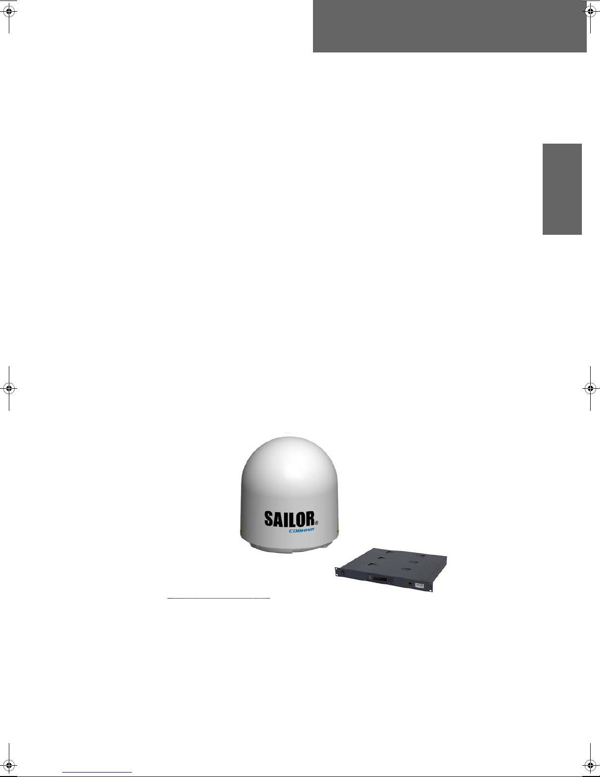
2.1 SAILOR 900 VSAT system
The SAILOR 900 VSAT is a unique stabilized maritime VSAT antenna system operating in
the Ku-band (10.7 to 14.5 GHz). It provides bi-directional IP data connections both on
regional satellite beams and quasi-global Ku-band satellite networks. The system only
requires a single 50 Ohm cable to provide the Above Deck Unit with both DC power, data
and control information. The radome does not have to be removed neither before nor after
the installation. To protect the Above Deck Unit the built-in DC motors act as brakes during
transport and when the Above Deck Unit is not powered. The ADU system can be accessed
remotely and in-depth performance analysis can be done using the built-in web interface.
The SAILOR 900 VSAT system consists of the following units:
•Above Deck Unit (ADU)
• Antenna Control Unit (ACU)
The following figure shows the SAILOR 900 VSAT system.
Figure 2-1: Above Deck Unit and Antenna Control Unit (ACU)
98-138976-C 2-1
SAILOR 900 VSAT system
SAILOR 900 VSAT features
Single 50 Ohm coax cable for the ADU.
Support of several VSAT modems.
Gyro-free operation.
Ku-to-Ka-band conversion
Dual antenna mode.
SNMP support.
Service communication using SAILOR FleetBroadband over WAN.
Remote or local simultaneous software update of ADU and ACU via PC and Internet
browser.
Global RF configuration.
Full remote control and troubleshooting with built-in test equipment (BITE).
ACU with 4 x LAN, NMEA 0183, NMEA 2000, RS-232 and RS-422.
All interfaces at the ACU, no additional units required.
DC powered. Start up voltage: 22 VDC guaranteed, operating range: 20 – 32 VDC.
No scheduled maintenance.
2.1.1 Above Deck Unit (ADU)
The SAILOR 900 VSAT ADU is a 103 cm VSAT stabilised tracking antenna, consisting of a
suspended antenna with a standard global RF configuration. The ADU’s weight is 126,5 kg.
It is stabilized by heavy duty vibration dampers in 3-axis (plus skew) and can be used in
environments with elevations of -25° to + 125°. The ADU is powered by the ACU and
protected by a radome.
Figure 2-2: Above Deck Unit (ADU)
2-2 Chapter 2: Introduction 98-138976-C
Introduction
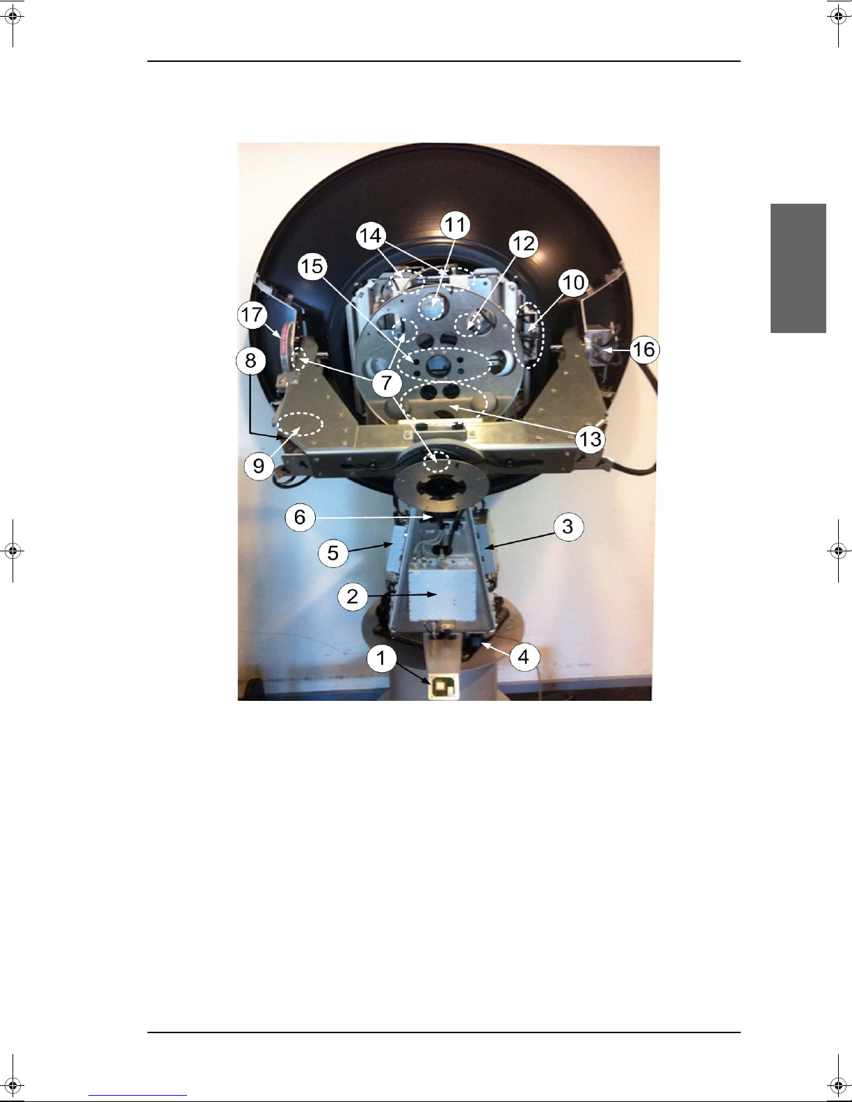
Modules in the SAILOR 900 VSAT ADU
SAILOR 900 VSAT system
1. GPS module.
2. VSAT Interface Module (VIM).
3. Pedestal Control Module (PCM).
4. Service switch.
5. DC-Motor Driver Module for cross elevation (DDM).
6. Cross elevation motor and encoder.
7. Zero Reference Module (x4) (ZRM) (not visible on photo). (3 on this figure)
8. DC-Motor Driver Module for elevation (on the bottom) (DDM).
9. Elevation motor and encoder (not visible).
10.Polarisation Motor Module (PMM).
98-138976-C Chapter 2: Introduction 2-3
Figure 2-3: SAILOR 900: Above Deck Unit modules 1/2
SAILOR 900 VSAT system
11.Polarisation motor.
12.Polarisation encoder.
13.Block Up Converter (BUC).
14.Low Noise Block downconverter (x2), (LNB).
15.Ortho Mode Transducer (OMT) (not visible on photo).
16.Inertial Sensor Module (ISM).
17.Elevation locking pin to lock the antenna dish in a fixed position.
In switch-off position the DC Motor Driver modules and the BUC are turned off for safe
conditions during service and repair. The switch must be in on position for normal ADU
operation.
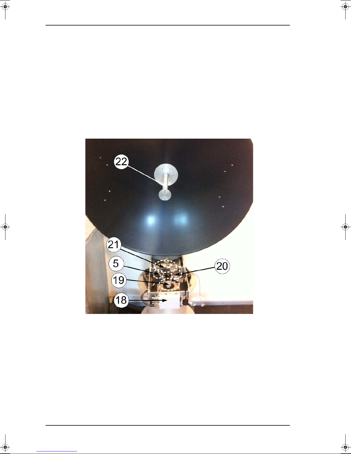
Figure 2-4: SAILOR 900: Above Deck Unit modules 2/2
18.DC-Motor Driver Module for Azimuth (DDM).
19.Azimuth motor.
20.Azimuth encoder.
21.Rotary joint.
22.Feed horn.
2-4 Chapter 2: Introduction 98-138976-C
 Loading...