

COBHAM SAILOR 6560, SAILOR 6561, SAILOR 6571, SAILOR 6570 User Manual
SAILOR 65xx GNSS/DGNSS
User manual


SAILOR 65xx GNSS/DGNSS
User manual
Document number: 98-140657-A
Release date: June 16, 2015
i

Disclaimer
Any responsibility or liability for loss or damage in connection with the use of this product
and the accompanying documentation is disclaimed by Thrane & Thrane A/S. The
information in this manual is provided for information purposes only, is subject to change
without notice and may contain errors or inaccuracies. Manuals issued by Thrane & Thrane
A/S are periodically revised and updated. Anyone relying on this information should acquire
the most current version e.g. from www.cobham.com/communications-and-
connectivity/satcom, Service and support, or from the distributor. Thrane & Thrane A/S is
not responsible for the content or accuracy of any translations or reproductions, in whole or
in part, of this manual from any other source. In the event of any discrepancies, the English
version shall be the governing text.
Thrane & Thrane A/S is trading as Cobham SATCOM.
Copyright
© 2015 Thrane & Thrane A/S. All rights reserved.
Trademark acknowledgements
• SAILOR is a registered trademark of Thrane & Thrane A/S in the European Union and the
Unites States of America and other countries.
• Other product and company names mentioned in this manual may be trademarks or
trade names of their respective owners.
• This product contains Android™ software. Android is a trademark of Google Inc.
GPL notification
The software included in this product contains copyrighted software that is licensed under
the GPL/LGPL. The verbatim licenses can be found online at:
http://www.gnu.org/licenses/old-licenses/gpl-2.0.html
http://www.gnu.org/licenses/old-licenses/lgpl-2.1.html
You may obtain the complete corresponding source code from us for a period of three
years after our last shipment of this product, which will be no earlier than 2021, by sending
a money order or check for DKK 50 to:
SW Technology/GPL Compliance,
Cobham SATCOM (Thrane & Thrane A/S),
Lundtoftegaardsvej 93D
2800 Lyngby
DENMARK
Write "source for product GNSS/DGNSS Receiver" in the memo line of your payment. This
offer is valid to anyone in receipt of this information.
http://www.cobham.com/about-cobham/communications-and-connectivity/aboutus/satcom/free-and-open-source-software-(foss).aspx
ii

Safety summary
Observe the following general safety precautions during all phases of
operation, service and repair of this equipment. Failure to comply with
these precautions or with specific warnings elsewhere in this manual
violates safety standards of design, manufacture and intended use of the
equipment. Thrane & Thrane A/S assumes no liability for the customer's
failure to comply with these requirements.
Ground the equipment
To minimize shock hazard, connect the GNSS/DGNSS Receiver to an
electrical ground and follow the cable instructions.
Warranty limitation
IMPORTANT - The SAILOR 6286 DGNSS Antenna - Active and the SAILOR
6285 GNSS Antenna - Active are sealed waterproof units (classified IPx6
& IPx8). To create and maintain its waterproof integrity the antenna was
assembled in a controlled environment using special equipment. The
antennas and the GNSS/DGNSS Receiver are not user maintainable units,
they should under no circumstances be opened except by authorized
personnel. Unauthorized opening of the unit will invalidate the warranty.
Installation and service
Installation and general service must be done by skilled service personnel.
Compass safe distance
Compass safe distance: 30 cm (Standard magnetic compass), 20 cm
(Emergency magnetic compass) from the GNSS/DGNSS Receiver.
iii

Preface
Approvals
The GNSS/DGNSS Receiver is approved to MED 2011/75/EU and
fulfills the requirements in the standards:
IEC 61108-1 Ed. 2.0, 2003
IEC 61108-2 Ed. 1.0, 1998
IEC 61108-4 Ed. 1.0, 2004
IEC 61162-1 Ed. 4.0, 2010
IEC 61162-2 1998
IEC 61162-450 2011
IEC 60945 Ed. 4, 2002
MSC.302(87)
The approvals of the GNSS/DGNSS Receiver are constantly
monitored. New national approvals will be applied for and
granted and new test standards may come into force. Therefore
the above list may not be complete. Contact your authorized
dealer for more information.
About the manual
Intended readers
This manual is a user manual for the GNSS/DGNSS Receiver. This
manual is intended for anyone who is using or intends to use
this system. It is important that you observe all safety
requirements listed in the beginning of this manual, and operate
the system according to the guidelines in this manual.
Note that this manual does not cover installation of the system.
For information on installation refer to the installation manual.
Part numbers for related manuals are listed in the next section.
iv
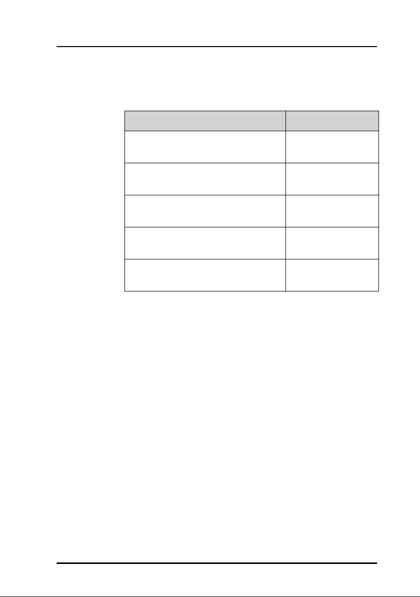
Related documents
The following table shows the documents related to this manual
and to the GNSS/DGNSS Receiver.
Title and description Document number
Typography
SAILOR 6588 GNSS/DGNSS Receiver,
Installation manual
SAILOR 6004 Control Panel,
Installation manual
SAILOR 6588 GNSS/DGNSS Receiver,
Installation guide
SAILOR 6286 DGNSS Antenna - Active,
Installation guide
SAILOR 6285 GNSS Antenna - Active,
Installation guide
In this manual, typography is used as indicated below:
Bold is used for the following purposes:
• To emphasize words.
Example: “Do not touch the antenna”.
• To indicate what the user should select in the user interface.
Example: “Select SETTINGS > LAN”.
Italic is used to emphasize the paragraph title in crossreferences.
Example: “For further information, see Connecting Cables
on page...”.
98-145263
98-136644
98-140656
98-141644
98-136019
v

vi

Table of contents
Chapter 1 Introduction
Introduction to GNSS and DGNSS ............................................... 1
Overview ......................................................................................................................1
The GNSS or DGNSS system ...........................................................2
System configuration ............................................................................................ 4
System components ........................................................................... 4
SAILOR 6588 DGNSS Receiver .........................................................................4
SAILOR 6285 GNSS Antenna - Active ...........................................................5
SAILOR 6286 DGNSS Antenna - Active ........................................................ 6
SAILOR 6004 Control Panel ...............................................................................6
Chapter 2 Operation
To get started .........................................................................................7
To dim the display of the Control Panel .......................................................7
Startup screen ........................................................................................................... 8
GNSS/DGNSS menu screen .............................................................................10
Position ...................................................................................................11
Anchor Watch ..................................................................................... 19
Trip Counters ....................................................................................... 21
Settings ...................................................................................................23
To change a setting ............................................................................................. 23
Settings – General ................................................................................................ 24
Settings – Radio Beacons .................................................................................29
Settings – Alerts .................................................................................................... 30
Alert and notification management ......................................... 31
List of alerts ..........................................................................................35
Multiple receivers .............................................................................. 37
Alerts and notifications in a multiple-receiver system ....................... 38
vii

Table of contents
Chapter 3 Service & maintenance
Maintenance ........................................................................................39
Contact for support .............................................................................................39
Service interface ....................................................................................................40
System LEDs ............................................................................................................42
Troubleshooting guide ....................................................................43
Service and repair .............................................................................. 45
Applicable SAILOR part numbers ...................................................................45
Accessories ...............................................................................................................46
To remove the cover ...........................................................................................47
To replace the fuse ...............................................................................................48
To repack for shipment ......................................................................................48
App. A Specifications
SAILOR 6588 GNSS/DGNSS Receiver ...................................... 51
SAILOR 6285 GNSS Antenna - Active ..................................... 52
SAILOR 6286 DGNSS Antenna - Active .................................. 53
SAILOR 6004 Control Panel .........................................................54
NMEA sentences ................................................................................55
Glossary .....................................................................................................................57
Index .....................................................................................................................59
viii

Chapter 1
Introduction 1
This chapter introduces the GNSS/DGNSS Receiver and gives an overview
of the system and services. It has the following sections:
• Introduction to GNSS and DGNSS
• The GNSS or DGNSS system
• System components
Introduction to GNSS and DGNSS
Overview
A GNSS receiver processes the signals transmitted by the satellites of Global
Navigation Satellite Systems (GNSS). The GNSS receiver determines the
position, velocity, and precise time by processing the signals broadcast by
GNSS satellites.
Introduction
A DGNSS receiver (Differential GNSS) is an enhancement to a GNSS
receiver. It can utilize a global network of ground-based reference stations
for improved position accuracy. The ground-based reference stations
compare their known fixed positions with the positions calculated from the
received GNSS satellite signals. The differences are transmitted via radio
beacons to the DGNSS Receiver, which can use them to calculate a more
precise position. In order to be able to apply high-quality corrections, the
selected reference station must be near the DGNSS receiver to ensure that
they both observe roughly the same GNSS satellites.
1

Chapter 1: Introduction
The GNSS or DGNSS system
The GNSS/DGNSS Receiver is available in variants as listed in table 1.
Depending on the antenna used the Receiver will either be a GNSS or a
DGNSS Receiver. Using the SAILOR 6285 GNSS Antenna - Active gives a
GNSS Receiver variant and the SAILOR 6286 DGNSS Antenna - Active gives
a DGNSS Receiver variant.
Both variants can be controlled by the SAILOR 6004 Control Panel. The
Control Panel is connected to the GNSS/DGNSS Receiver through a LAN
connection.
Features
Position calculation with GPS and/or GLONASS satellites.
Reception and use of differential corrections from SBAS, RTCM SC-104
via a serial interface or the integrated radio beacon receiver.
RAIM calculation according to IEC 61108-1. Estimates the calculated
1
positions accuracy and monitors the signal integrity.
SBAS corrections from EGNOS, MSAS, WAAS, GAGAN and SDCM.
Automatic or manual radio beacon station selection.
Support for other datums, including a user defined.
Serial inputs and outputs according to IEC 61162-1/2. Fully
1
configurable for each port.
Light Weight Ethernet interface according to IEC 61162-450. Fully
configurable.
Alert management according to MSC.302. Fully configurable.
Support for High Speed Craft (HSC).
Antenna offset correction.
Anchor Watch.
1. DGNSS only
2 The GNSS or DGNSS system
Two Trip Counters and a total counter.
Speed log output.
Pulse Per Second (PPS) output.
Chapter 1: Introduction
Interface for ThraneLink applications and INS available.
Touch screen on the SAILOR 6004 Control Panel.
Possibility for multiple-receiver setup with up to three GNSS/DGNSS
Receivers.
Up to four Control Panels on the same GNSS/DGNSS Receiver.
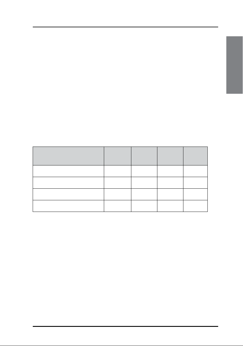
System variants
The following variants are available:
Variant
DGNSS
Receiver
SAILOR 6560 GNSS System x x x
SAILOR 6561 GNSS Basic x x
SAILOR 6570 DGNSS System x x x
SAILOR 6571 DGNSS Basic x x
Table 1: System variants
All variants include the DGNSS or GNSS App for the Control Panel. The
application is an integrated part of the GNSS/DGNSS Receiver.
GNSS
antenna
DGNSS
antenna
Control
Panel
Introduction
The GNSS or DGNSS system 3
Chapter 1: Introduction
SAILOR 6286
DGNSS Antenna - Active
GNSS Antenna - Active
SAILOR 6285
SAILOR 6004 Control Panel
ACC
AUX
TEST
PWR
12-24 VDC12-24 VDC
SAILOR 6588 DGNSS Receiver
DGNSS Receiver
6588
CORR
RAIM
Power
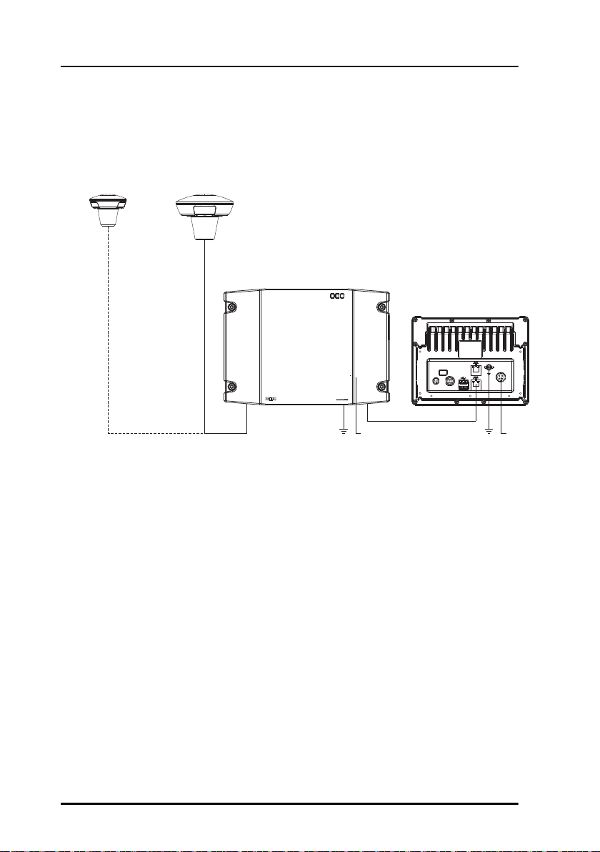
System configuration
The following figure shows the units of a GNSS or DGNSS system.
Figure 1: System configuration
System components
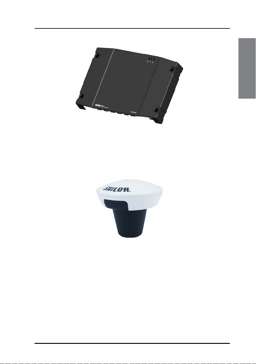
SAILOR 6588 DGNSS Receiver
4 System components
The DGNSS Receiver is the main unit in a DGNSS or GNSS position system.
The DGNSS Receiver is always on, provided there is DC power. It has a
connector for the GNSS or DGNSS antenna, a ground connection, springloaded terminals for DC power (12–24 VDC) and a dual LAN connector. The
DGNSS Receiver has spring-loaded terminals for connection to various
inputs and outputs.
Chapter 1: Introduction
Figure 2: SAILOR 6588 DGNSS Receiver
SAILOR 6285 GNSS Antenna - Active
The SAILOR 6285 GNSS Antenna - Active is a robust, sealed and waterproof
GPS and GLONASS antenna (classified IPx6 & IPx8).
Introduction
Figure 3: SAILOR 6285 GNSS Antenna - Active
System components 5
Chapter 1: Introduction
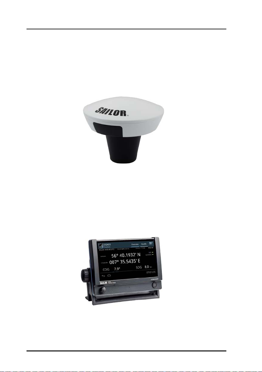
SAILOR 6286 DGNSS Antenna - Active
The SAILOR 6286 DGNSS Antenna - Active is a robust, sealed and
waterproof GPS and GLONASS antenna. This antenna also has an antenna
for receiving differential corrections from radio beacon stations in the LW
frequency band.
Figure 4: SAILOR 6286 DGNSS Antenna - Active
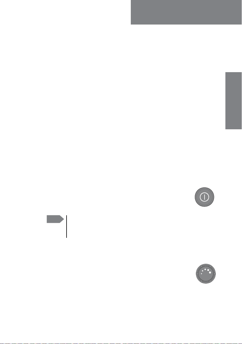
SAILOR 6004 Control Panel
The Control Panel is the user interface for the GNSS/DGNSS Receiver. Alerts
are shown in the display. The Control Panel has a touch screen and a buzzer
for alert tones. The display can be dimmed. The Control Panel has a color
LCD screen and the nominal viewing distance is 0.9 m.
Figure 5: SAILOR 6004 Control Panel
6 System components
Chapter 2
Operation 2
This chapter has the following sections:
• To get started
• Position
• Anchor Watch
• Trip Counters
• Settings
• Alert and notification management
• List of alerts
• Multiple receivers
To get started
As soon as DC power is provided the GNSS/DGNSS Receiver is on.
Operation
To switch on the Control Panel push the power button.
Operate the Control Panel by tapping the touch screen. To
switch off the Control Panel push and hold the power button
for 2 seconds and follow the instructions on the screen.
Note
If the remote switch in the Control Panel is wired and it is
switched on, you can only use the Power button to reboot the
Control Panel, you cannot switch it off.
To dim the display of the Control Panel
Turn the dim knob of the Control Panel to increase or decrease
the display brightness or tap Auto. To dim to level zero push
the power button once. If an alert appears while the display is in
level zero, the display returns to the latest dim value and the
alert is displayed.
7

Chapter 2: Operation
Startup screen
The Control Panel is a multipurpose touch display on which the DGNSS or
GNSS application has been installed during the installation of the
GNSS/DGNSS Receiver. The startup screen provides an icon-based
application menu including the DGNSS or GNSS application. To start the
DGNSS or GNSS application tap the DGNSS or GNSS icon on the Control
Panel display.
Figure 6: Startup screen (example for DGNSS)
The application menu also includes the general Control Panel System
application providing application management and general Control Panel
settings. For details see the installation manual of the Control Panel.
Bottom bar
The general bottom bar of the Control Panel is always available below the
startup application menu or the currently running application.
Figure 7: Bottom bar
The left side of the bottom bar contains general navigation icon buttons:
Back button
8 To get started
Chapter 2: Operation
Tap the back button to return to the previous screen/page of the current
application or close the current application. If you tap this icon when being
in the GNSS or DGNSS menu screen, you navigate to the startup screen.
Hide keyboard button
Tap the hide keyboard button to remove the on screen keyboard. This
button replaces the back button when the on screen keyboard is shown.
Home button
Tap the home button to return to the startup screen.
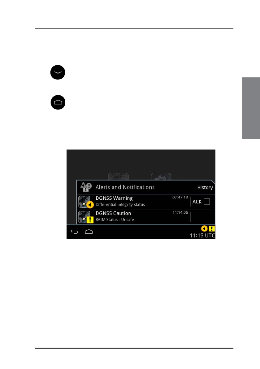
The right side of the bottom bar contains indication icons (if there are any
active indications) from alert or notifications and contains also the UTC
time. Tap this area to open the alert and notifications list.
Figure 8: Alerts and notifications
Tap the same area again or tap the back button to close the list. See Alert
and notification management on page 31 for more details on alerts and
notifications.
Operation
To get started 9
Chapter 2: Operation
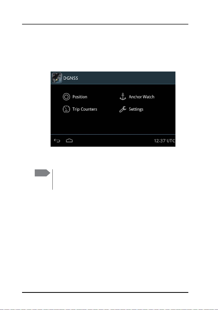
GNSS/DGNSS menu screen
Tap the DGNSS or GNSS icon on the startup screen to display the menu
screen. From this screen you access the main functions of the GNSS/DGNSS
Receiver.
Figure 9: Menu screen (example for DGNSS)
Tap Position, Anchor Watch, Trip Counters or Settings to proceed.
Note
10 To get started
The following sections describe the DGNSS app. The functionality
that is not available in the GNSS system will be marked as DGNSS
only.
Chapter 2: Operation
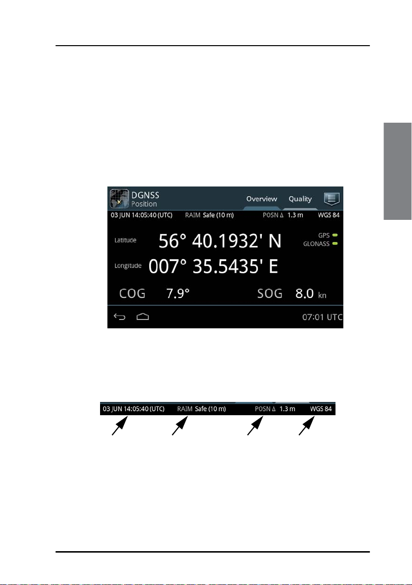
Position
The Position screen gives an overview of the current position and other
relevant status information. This screen has the tabs Overview and
Quality. Lists of GNSS satellites, SBAS satellites, beacons and beacon
messages can be accessed through the icon in the upper right corner. When
no position is calculated or the connection to the GNSS/DGNSS Receiver is
lost, the position information in this screen is frozen and the text color is
changed to yellow.
Operation
Figure 10: Position screen (example)
The following paragraphs describe the Overview tab.
Top information line
UTC time RAIM (Limit) Position delta Datum
Figure 11: Top information line
The UTC time in the position screen is the time of the displayed position.
When the position is lost this time does not change.
The RAIM status gives an indication of the quality of the calculated
position. A result of the RAIM calculation is the estimated position
Position 11
Chapter 2: Operation
accuracy, indicated in POSN field in the top information line. The
estimated position accuracy is compared to the RAIM accuracy limit
yielding the RAIM status. The RAIM accuracy limit is shown in parentheses.
You can set the accuracy limit in DGNSS > Settings > Accuracy RAIM.
Status Explanation
Safe The RAIM status is safe. The position accuracy is below the
set accuracy limit.
Caution The RAIM status is caution. There are not enough satellites
available to calculate RAIM.
Unsafe The RAIM status is unsafe. The position accuracy has
exceeded the set accuracy limit.
Table 2: RAIM status
The datum used for the current position is displayed to the right. For
example WGS 84. You can set the datum in DGNSS > Settings > General
> Datum.
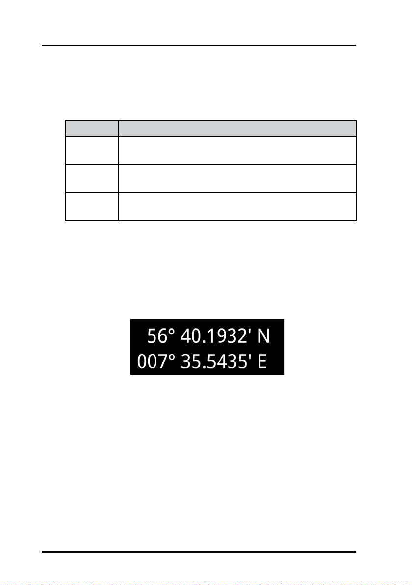
Latitude and longitude of the calculated position
Figure 12: Latitude and longitude (example)
“LED” status section:
The color “LED”s indicate the status of the system. Green color of the “LED”
means no issues (i.e. satellite system is used for position or valid beacon
data currently received) and amber color means there is an issue (i.e.
satellite system is not used for position or no valid beacon data currently
received).
12 Position
 Loading...