

COBHAM SAILOR 6300 User Manual
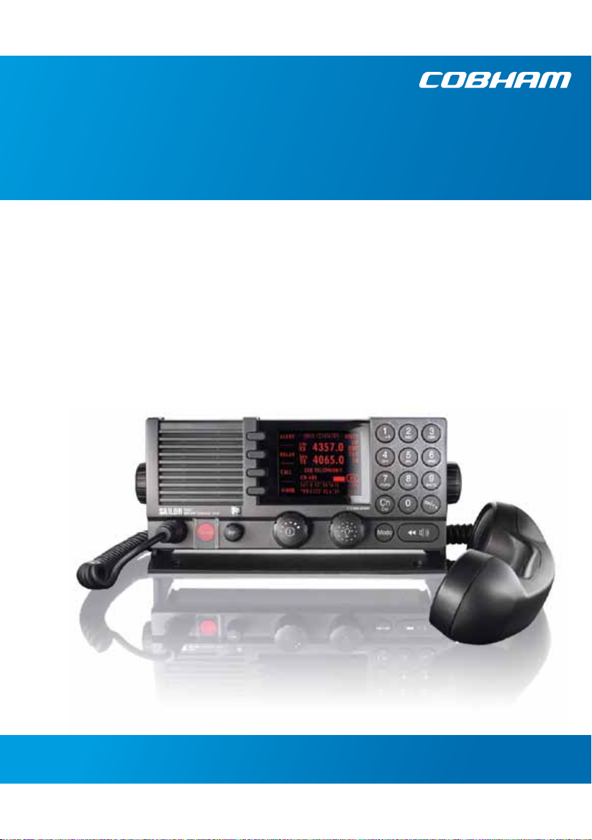
SAILOR 6300 MF/HF DSC
150W/150W FCC/250W/500W
User manual


SAILOR 6300 MF/HF DSC
150W/150W FCC/250W/500W
User manual
Document number: 98-131070-THR-E
Release date: December 7, 2015
i

Disclaimer
Any responsibility or liability for loss or damage in connection with the use of
this product and the accompanying documentation is disclaimed by Thrane &
Thrane A/S. The information in this manual is provided for information
purposes only, is subject to change without notice and may contain errors or
inaccuracies. Manuals issued by Thrane & Thrane A/S are periodically revised
and updated. Anyone relying on this information should acquire the most
current version e.g. from www.cobham.com/satcom, Service and support,
or from the distributor. Thrane & Thrane A/S is not responsible for the content
or accuracy of any translations or reproductions, in whole or in part, of this
manual from any other source. In the event of any discrepancies, the English
version shall be the governing text.
Thrane & Thrane A/S is trading as Cobham SATCOM.
Copyright
© 2015 Thrane & Thrane A/S. All rights reserved. Printed in Denmark.
Trademark Acknowledgements
• Thrane & Thrane is a registered trademark of Thrane & Thrane A/S in the
European Union and the Unites States of America.
• Other product and company names mentioned in this manual may be
trademarks or trade names of their respective owners.
GPL notification
The software included in this product contains copyrighted software that is
licensed under the GPL/LGPL. The verbatim licenses can be found online at:
http://www.gnu.org/licenses/old-licenses/gpl-2.0.html
http://www.gnu.org/licenses/old-licenses/lgpl-2.1.html
You may obtain the complete corresponding source code from us for a period
of three years after our last shipment of this product, which will be no earlier
than December 31, 2015, by sending a money order or check for DKK 50 to:
SW Technology/GPL Compliance,
Cobham SATCOM (Thrane & Thrane A/S),
Lundtoftegaardsvej 93D
2800 Lyngby
DENMARK
ii

Write "source for product SAILOR 6300 MF/HF DSC" in the memo line of your
payment. This offer is valid to anyone in receipt of this information.
http://www.cobham.com/about-cobham/communications-andconnectivity/about-us/satcom/free-and-open-source-software-(foss).aspx
You may also find a copy of the source at http://www.thrane.com/foss.
This offer is valid to anyone in receipt of this information.
Warranties
Any attempt to install or execute software not supplied by Thrane & Thrane
on this device will result in the warranty being void. Any attempt to modify
the software on this device in a way not specified by Thrane & Thrane will
result in the warranty being void.
iii
Safety summary
The following general safety precautions must be observed during all
phases of operation, service and repair of this equipment. Failure to
comply with these precautions or with specific warnings elsewhere in this
manual violates safety standards of design, manufacture and intended
use of the equipment. Thrane & Thrane assumes no liability for the
customer's failure to comply with these requirements.
GROUND THE EQUIPMENT
To minimise shock hazard, the equipment chassis and cabinet must be
connected to an electrical ground and the cable instructions must be
followed.
DO NOT OPERATE IN AN EXPLOSIVE ATMOSPHERE
Do not operate the equipment in the presence of flammable gases or
fumes. Operation of any electrical equipment in such an environment
constitutes a definite safety hazard.
KEEP AWAY FROM LIVE CIRCUITS
Operating personnel must not remove equipment covers. Component
replacement and internal adjustment must be made by qualified
maintenance personnel. Do not service the unit with the power cable
connected. Always disconnect and discharge circuits before touching
them.
Service
General service must be done by skilled service personnel.
Caution! Electric shock hazard. Do not open the
equipment. Only skilled service personnel may
service and repair the equipment.
iv
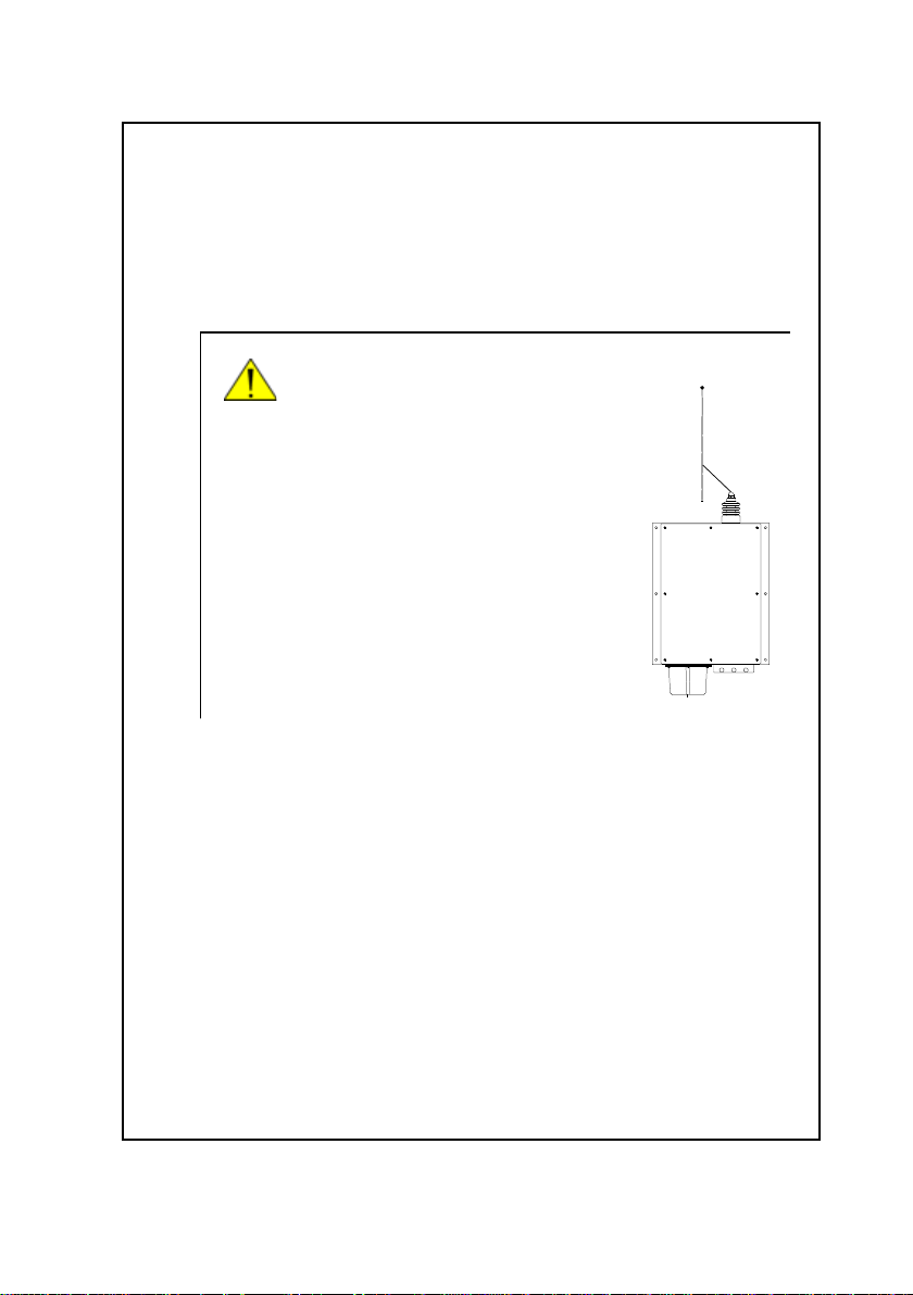
RF exposure hazards and instructions
Unit
Antenna Tuning
MF/HF
SAILOR 638x
Your Thrane & Thrane radio generates electromagnetic RF (radio
frequency) energy when transmitting. To ensure that you and those
around you are not exposed to excessive amounts of energy and thus to
avoid health hazards from excessive exposure to RF energy, all persons
must obey the following:
Caution! Never touch the
Antenna Tuning Unit or
feeder wire when the
MF/HF radio is
transmitting. High
voltage which can
cause death or serious
injury is present at the
locations shown in the
illustration below.
Warranty limitation
The radio is not a user maintainable unit, and under no circumstances
should the unit be opened except by authorized personnel. Unauthorized
opening of the unit will invalidate the warranty.
v
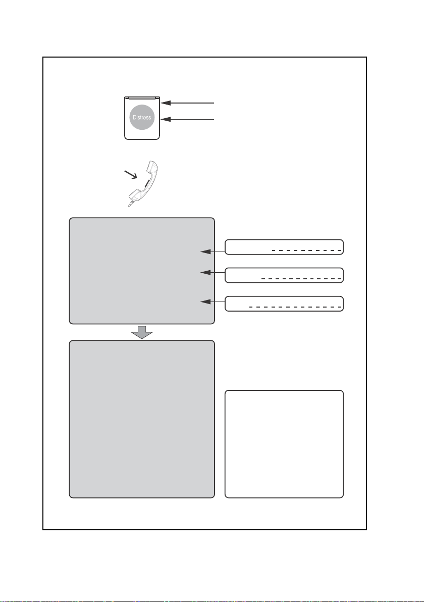
Emergency calls
Press
MM
AA
YY
DD
AA
YY
-M-M
M
MM
A
AA
Y
D
YY
DD
NANA
NA
NANA
AA
A
Y
-M
A
AA
YY
-M-M
AA
This is
ME-NAME-NA
ME-NA
ME-NAME-NA
CC
ALAL
C
AL
CC
ALAL
or other IDENTIFICATION
YY
DD
AA
YY
Y
D
A
Y
YY
DD
AA
YY
ME-NAME-NA
ME-NA
ME-NAME-NA
LL
SS
IGNIGN
L
S
IGN
LL
SS
IGNIGN
-M-M
-M
-M-M
Use the
AA
YY
DD
A
Y
D
AA
YY
DD
MEME
ME
MEME
LL
ifif
t Ct C
ovov
L
LL
PP
P
PP
until beep sounds continuously
(more than 3 seconds)
HANDHAND
SS
HAND
S
HANDHAND
SS
AA
YY
A
Y
YY
AA
erer
if
t C
ov
er
ifif
t Ct C
ovov
erer
rr
ee
ss
s RED Buttons RED Button
r
e
s
s RED Button
rr
ee
ss
s RED Buttons RED Button
ETET
ET
for voice calling
ETET
SHIP‘s NAME:
CALLSIGN:
OWN OWN
OWN
OWN OWN
IDID
ID
IDID
MM
MM
SS
M
M
S
MM
MM
SS
(If the initial alert is sent by DSC)
MM
AA
YY
DD
AA
M
A
Y
D
A
MM
AA
YY
DD
AA
NANA
MEME
NA
ME of the
NANA
MEME
CC
ALAL
LL
SS
IGNIGN
C
AL
L
S
IGN or other
CC
ALAL
LL
SS
IGNIGN
(If the initial alert is sent by DSC)
given as
If latitude and longitude are not known
or if time is insufficient,
in relation to a known geographical location
Kind of
Any other useful
VV
EE
SS
V
E
S
VV
EE
SS
IDENIDEN
IDEN
IDENIDEN
MM
MM
SS
M
M
S
MM
MM
S
S
PP
OO
SS
ITIT
P
O
S
IT
PP
OO
SS
ITIT
ll
atat
itit
udeude
l
at
it
ude and
ll
atat
itit
udeude
or
NANA
TURETURE
NA
TURE of distress
NANA
TURETURE
AA
SS
SS
II
SS
TT
ANCANC
A
S
S
I
S
T
ANC
AA
SS
SS
II
SS
TT
ANCANC
INFINF
INF
INFINF
SS
ELEL
S
EL in distress
SS
ELEL
II
I
II
IONION
ION
IONION
vi
II
I
II
YY
Y
YY
TT
IFICIFIC
T
IFIC
TT
IFICIFIC
longitlongit
longit
longitlongit
EE
E required
EE
AA
OROR
MM
M
A
OR
AA
OROR
MM
TT
T
TT
AA
TT
A
T
AA
TT
udeude
ude
udeude
IONION
ION
IONION
IONION
ION
IONION
MMSI:
DIDI
SS
TRETRE
SS
SS
and C and C
OMOM
MM
UNICUNIC
AA
DI
S
TRE
S
S
and C
SS
SS
and C and C
FREQUENCIEFREQUENCIE
FREQUENCIE
FREQUENCIEFREQUENCIE
DD
SCSC
RR
adiadi
D
SC
R
adi
DD
SCSC
RR
adiadi
12290.0 kHz
16420.0 kHz
OM
OMOM
otot
elephonelephon
ot
elephon
otot
elephonelephon
Channel 16
2182.0 kHz
4125.0 kHz
6215.0 kHz
8291.0 kHz
DIDI
SS
TRETRE
_ _ _ _ _ _ _ _ _ _ _ _ _ _ _ _ _ _ _ _ _ _ _ _ _ _ _ _ _ _ _ _ _ _ _ _
VHF
Channel 70
MF
2187.5 kHz
HF4
4207.5 kHz
HF6
6312.0 kHz
HF8
8414.5 kHz
HF12
12577.0 kHz
HF16
16804.5 kHz
_ _ _ _ _ _ _ _ _ _ _ _ _ _ _ _ _ _ _ _ _ _ _ _ _ _ _ _ _ _ _ _ _ _ _ _
Remember to use the correct HF-procedures
Don‘t forget your EPIRB is the secondary means of
alerting
M
MM
UNIC
UNICUNIC
SS
S
SS
yy
y
yy
TT
A
T
AA
TT
NBDPNBDP
NBDP
NBDPNBDP
- - - - -
2174.5 kHz
4177.5 kHz
6268.0 k Hz
8376.5 kHz
12520.0 kHz
16695.0 kHz
IONION
ION
IONION
99-132140

Preface
Radio for occupational use
TT-6300 MF/HF DSC fulfils the requirements of SOLAS and is
intended for use in maritime environment.
SAILOR 6300 MF/HF DSC is designed for occupational use only
and must be operated by licensed personnel only.
SAILOR 6300 MF/HF DSC is not intended for use in an
uncontrolled environment by general public.
Manual overview
This manual has the following chapters:
• Introduction contains a description of the MF/HF radio and
its components.
• Operation explains how to start up the radio, make and
receive voice, Distress and DSC calls, including how to
handle multiple sessions, Watch and Replay.
• Service & maintenance contains support information
including a weekly check, diagnostics and a troubleshooting
guide.
vii

Training information (for FCC approved equipment)
The TT- 6300B MF/HF DSC is designed for occupational use
only and is also classified as such. It must be operated by
licensed personnel only. It must only be used in the course of
employment by individuals aware of both the hazards as well as
the way to minimize those hazards.
The radio is thus NOT intended for use in an uncontrolled
environment by general public. The SAILOR 6300 MF/HF DSC
has been tested and complies with the FCC RF exposure limits
for Occupational Use Only. The radio also complies with the
following guidelines and standards regarding RF energy and
electromagnetic energy levels including the recommended
levels for human exposure:
• FCC OET Bulletin 65 Supplement C, evaluating compliance
with FCC guidelines for human exposure to radio frequency
electromagnetic fields.
• American National Standards Institute (C95.1) IEEE standard
for safety levels with respect to human exposure to radio
frequency electromagnetic fields, 3 kHz to 300 GHz
• American National Standards Institute (C95.3) IEEE
recommended practice for the measurement of potentially
hazardous electromagnetic fields - RF and microwaves.
Warning
viii
Below the RF exposure hazards and instructions in safe
operation of the radio within the FCC RF exposure limits
established for it are described.
The SAILOR radio set generates electromagnetic RF (radio
frequency) energy when transmitting. To ensure that no
personnel will be exposed to excessive amounts of RF-energy
and to avoid health hazards from excessive exposure to RF
energy, the following safety distances must be followed:

Antenna Safety distance
150W Calculated: 1.71 m or 5.7 feet
250W Calculated: 2.21 m or 7.3 feet
500W Calculated: 3.12 m or 10.3 feet
Calculations cover a whip antenna with a maximum gain of 3dBi,
worst case frequency (30 MHz), full power and 100% duty cycle
(transmitter always on) considering the most conservative limits
mentioned in:
• FCC OET Bulletin 65 (1997)
• Canada RSS102 (2010)
• Canada Safety Code 6 (2015)
Installation Example for 150W
1. A whip antenna with a maximum gain of 3 dBi must be
mounted at least 12.3 ft. (3.71m) above the highest deck
where people may be staying during continuous radio
transmissions. The distance is to be measured vertically from
the lowest point of the antenna. This provides the minimum
separation distance which is in compliance with RF exposure
requirements and is based on the MPE radius of 5.7 feet
(1.71 m) plus the 6.6 ft. (2.0 m) height of an adult.
2. On vessels that cannot fulfill requirements in item 1, the
antenna must be mounted so that the lowest point of the
antenna is at least 5.7 feet (1.71m) vertically above the
heads of people on deck and all persons must be outside the
5.7 feet MPE radius during radio transmission.
• Always mount the antenna at least 5.7 feet from possible
human accessNever touch the antenna when
transmitting.
• Never touch the antenna when transmitting.
• Use only authorized T&T accessories.
• Only allow trained and certified operators knowing about
RF-energy and hazards to operate the radio.
ix
3. If the antenna has to be placed in public areas or near people
with no awareness of the radio transmission, the antenna
must be placed at an even greater distance. Consult the
appropriate standard for exact limits, depending on national
specifications.
Failure to observe any of these warnings may cause RF exposure
exceeding above mentioned limits or create dangerous
conditions.
Related documents
Title and description
SAILOR 630x MF/HF Control Unit,
Installation Guide
SAILOR 6300 MF/HF Transceiver Unit
& Antenna Tuning Unit 150/250/500
W, Installation Guide
SAILOR 6000 MF/HF 150/250/500 W
System, Installation Manual
SAILOR 6300 MF/HF Radiotelex,
User Manual
SAILOR 6101 and SAILOR 6103 Multi
Alarm Panel, Installation and User Manual
Emergency call sheet 98-132369
Document
number
98-132396
98-133081
98-144542
98-130890
98-144591
98-132519
98-130981
x

Table of contents
Chapter 1 Introduction
SAILOR 6301 Control Unit DSC Class A ....................................1
Accessories available ..........................................................................6
Chapter 2 Operation
Overview ................................................................................................ 11
General use and navigation ..........................................................11
Basic MF/HF radio communication ..........................................19
Watch function ...................................................................................21
Scan ..........................................................................................................22
DSC calls .................................................................................................23
Phone book ...........................................................................................38
Radiotelex ..............................................................................................41
Replay function ..................................................................................42
Setup ........................................................................................................43
Chapter 3 Service & maintenance
Overview ................................................................................................ 53
Contact for support ..........................................................................53
Maintenance ........................................................................................ 53
Troubleshooting ................................................................................. 56
Diagnostics ...........................................................................................58
Warranty and returning units for repair ..................................63
xi

Table of contents
Glossary .....................................................................................................................65
Index .....................................................................................................................67
xii
Chapter 1
Introduction 1
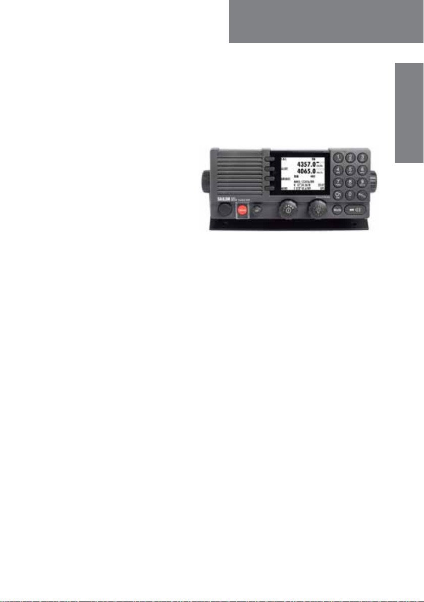
SAILOR 6301 Control Unit DSC Class A
The SAILOR 6301 Control
Unit DSC Class A is a modular
and flexible MF/HF radio that
can be customized to your
specific needs for MF/HF
communication on work
boats, high seas fishing
vessels and merchant vessels
of all kinds. It offers simplex and semi-duplex SSB radiotelephony in the
maritime mobile frequency bands from 150 kHz to 30 MHz. Services
include voice transmissions, watch function, DSC operations (Distress calls,
position info, Distress relay and more) and AM Broadcast reception.
The large display shows Rx and Tx frequencies and status, MMSI number,
position information, system and channel properties, including indicators
for transmission power and received signal strength. It is easy to read from
almost all angles and the display light can be adapted to dark environments.
Red text is shown on a black background providing good visibility in low
light conditions while protecting night vision.
Introduction
DSC operations are made using the four soft keys next to the display. The
MF/HF radio can replay the last 240 s of received voice. This is a useful
feature to minimize misunderstandings and to record audio when the radio
is unattended. The SAILOR 6301 Control Unit has an Ethernet interface to
connect to other equipment for control, monitoring and printing.
The SAILOR 6301 Control Unit is available as a basic MF DSC radio that can
be upgraded with an HF DSC option and/or a telex option. Telex is sent
using the SAILOR 6006 Message Terminal.
1

Chapter 1: Introduction
Features
Rugged and reliable design.
Full power range on all ITU channels: 1.6 — 30 MHz for 150 W, 250 W
and 500 W systems (Reduced power in the frequency range 1.6 —
4.0 MHz for 500 W according to legislation).
Powerful transceiver (150, 250 or 500 W).
Outdoor automatic antenna tuning unit.
Radiotelex using the SAILOR 6006 Message Terminal
Optionally 6 DSC Distress frequency watch keeping receiver.
Intelligent scanning for Voice, DSC and radiotelex (optional).
Ethernet with ThraneLINK.
Compliant with GMDSS in sea areas A2, A3 and A4 (Wheelmark).
Fulfills DSC specification ITU493-13.
2 SAILOR 6301 Control Unit DSC Class A
Chapter 1: Introduction
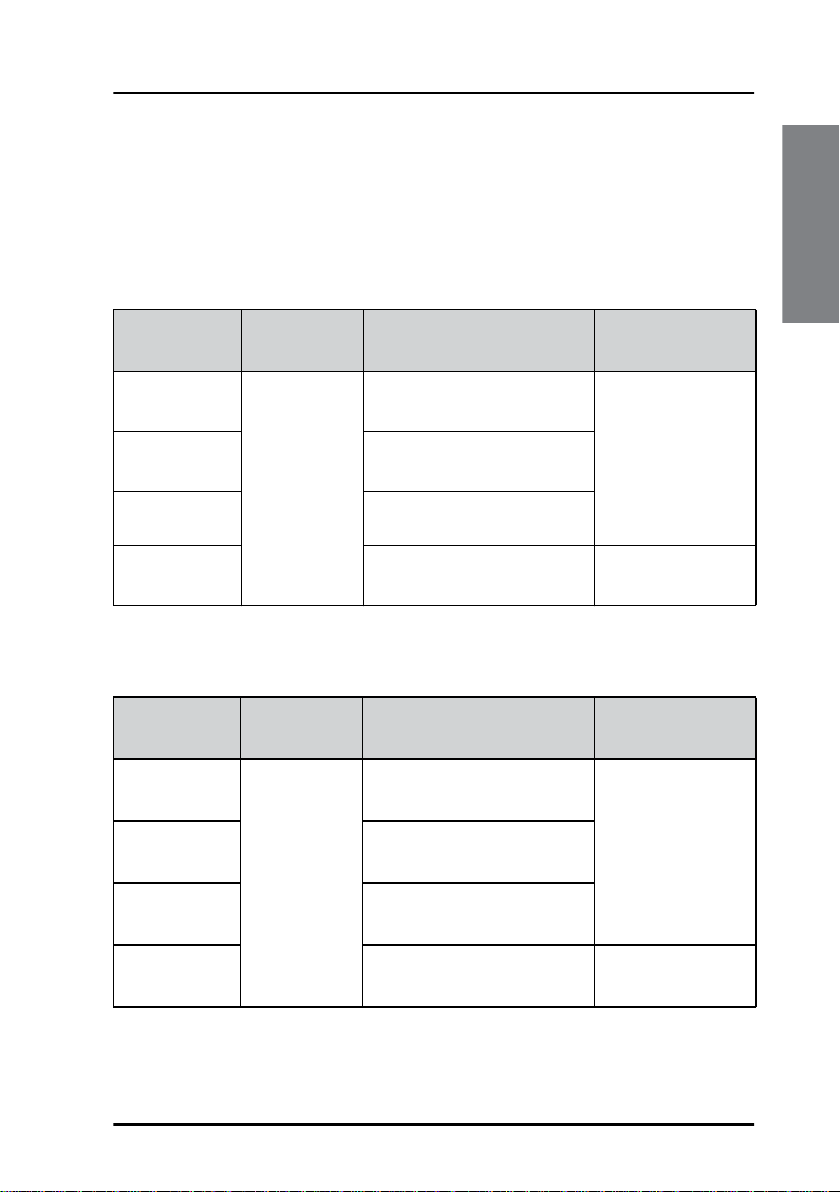
System overview
The MF/HF radio consists of a Control Unit with a handset, a Transceiver
Unit and an automatic Antenna Tuning Unit. The MF/HF radio is available in
the following power classes:
System sales item numbers 4063xxA-00500
Introduction
System
406310A-00500
SAILOR 6310
406311A-00500
SAILOR 6311
406320A-00500
SAILOR 6320
406350A-00500
SAILOR 6350
a. An additional SAILOR 6301 Control Unit can be added.
Control
Unit
SAILOR 6301
Control Unit
DSC Class A
Transceiver Unit
SAILOR 6310 MF/HF 150 W SAILOR 6384 ATU
a
SAILOR 6365 MF/HF 150 W FCC
SAILOR 6368 MF/HF 250 W
SAILOR 6369 MF/HF 500 W SAILOR 6383 ATU
System sales item numbers 4063xxB-00500
System
406310B-00500
TT-6310B
406311B-00500
TT-6311B
406320B-00500
TT-6320B
406350B-00500
TT-6350B
Control
Unit
SAILOR 6301
Control Unit
DSC Class A
Transceiver Unit
SAILOR 6365 MF/HF 150 W SAILOR 6384 ATU
a
SAILOR 6366 MF/HF 150 W FCC
SAILOR 6368 MF/HF 250 W
SAILOR 6369 MF/HF 500 W SAILOR 6383 ATU
Antenna T uning
Unit
Antenna T uning
Unit
a. An additional SAILOR 6301 Control Unit can be added.
SAILOR 6301 Control Unit DSC Class A 3
Chapter 1: Introduction
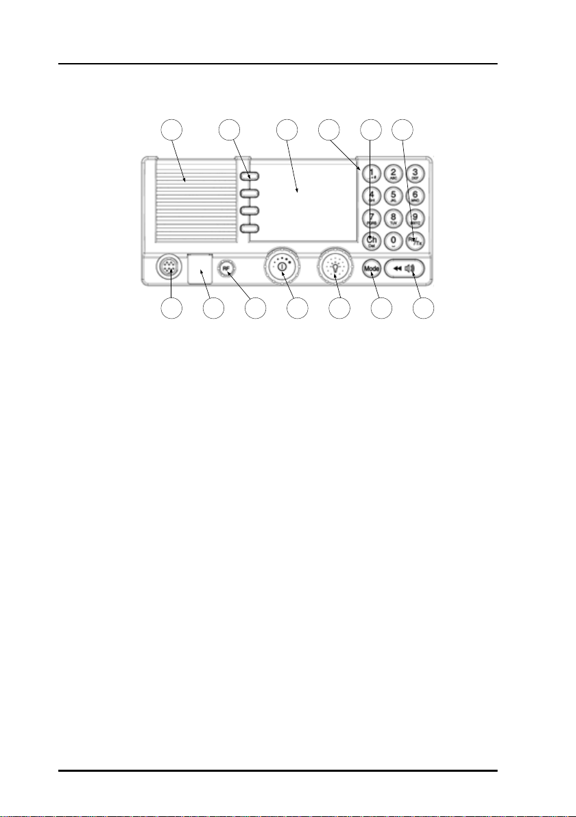
Controls on the front
1. Loudspeaker.
2. Four soft keys with function title in the display.
3. Large TFT color display.
4. Alphanumerical keys to enter Rx or Tx frequency or text strings.
5. CH button for channel selection.
6. Rx/Tx Key to enter Tx or Rx frequency.
7. Connector for handset or handmicrophone.
8. Distress button for sending a Distress alert.
9. RF gain control.
10.Volume knob with key-press function for power on/off.
11.Selector and dim knob with key-press function for radio operation and
setup.
12.Mode key to select the work mode: SSB, AM, LSB (optional), DSC, Telex
(optional).
13.Replay button to play back up to 240 s voice messages.
4 SAILOR 6301 Control Unit DSC Class A
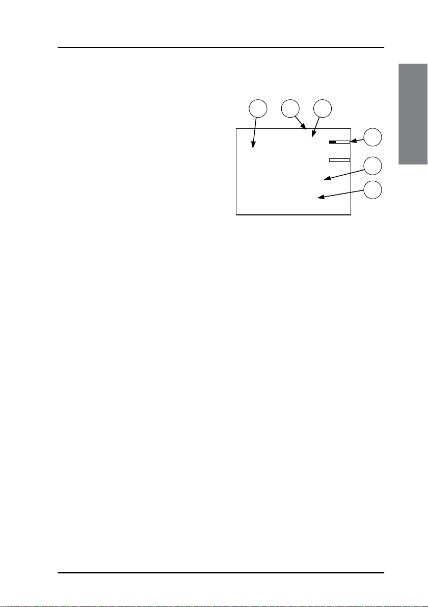
Display overview
Chapter 1: Introduction
The picture shows the display after
start-up. The display holds various
fields of information, depending on
the currently selected function.
1. Functions you can select with
the soft keys. If there are more
than 4 functions in the list press
the soft key MORE to display
further functions.
2. System property icons and engagement status.
3. Current receive and transmit frequency.
4. Channel properties with status and indicators for received signal
strength (Rx) and transmission power (Tx).
5. Service line containing mode of operation and channel number.
6. DSC window with MMSI number, position information and source.
For a detailed description of the information shown for each of the
functions available see the chapter Operation on page 11.
1 2 3
CALL
ALERT
DROBOS
MORE
SSB 401
MMSI: 123456789
N 12°34.5678
E 123°45.6789
SQ
4357.0
4065.0
kHz/Rx
kHz/Tx
22:07
GPS
4
5
6
Introduction
SAILOR 6301 Control Unit DSC Class A 5
Chapter 1: Introduction
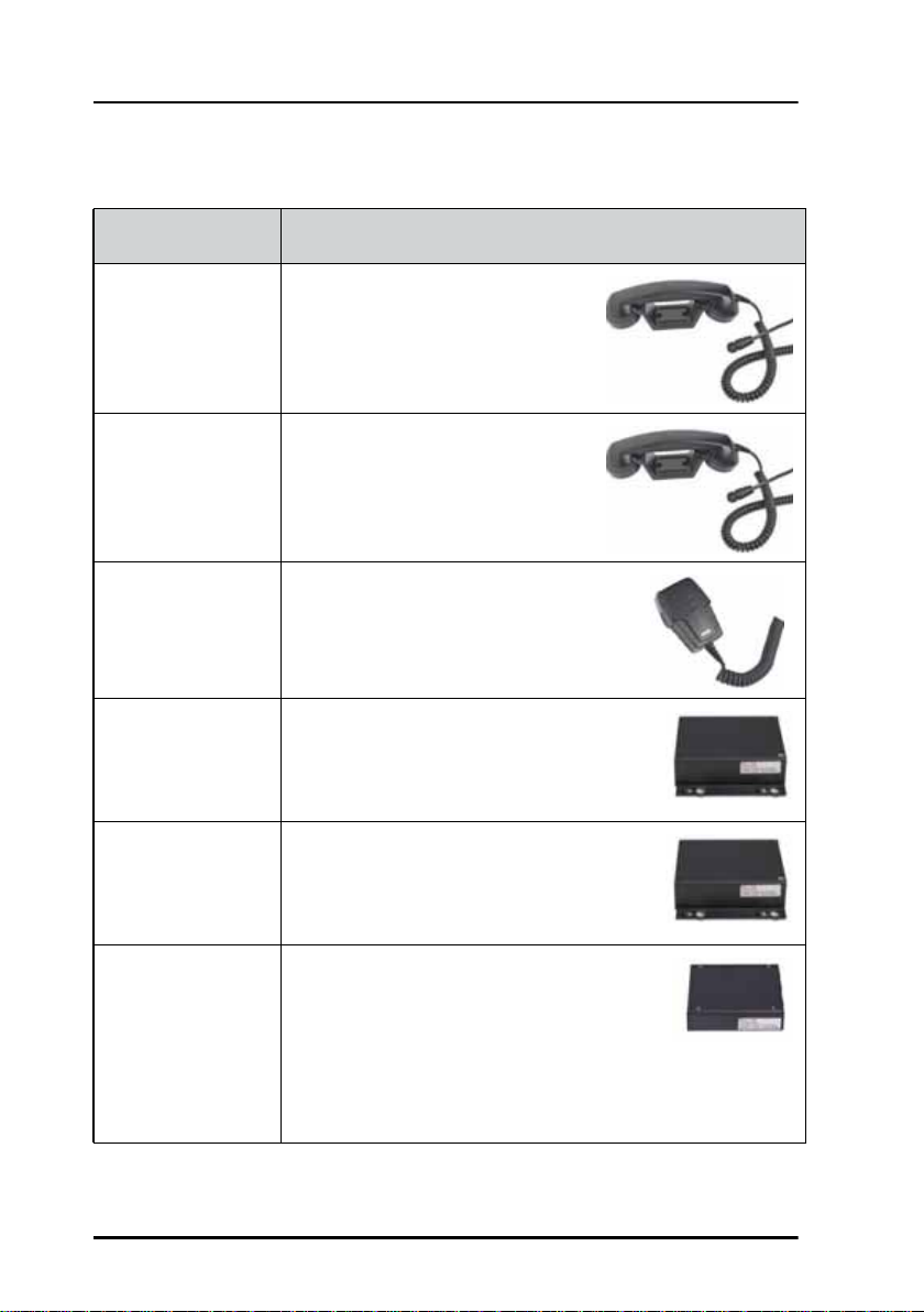
Accessories available
Accessory Description
SAILOR 6201
Handset with
cradle
SAILOR 6203
Handset with
cradle
SAILOR 6202
Hand Microphone
SAILOR 6207
Connection Box
for parallel
Handsets
SAILOR 6208
Control Unit
Connection Box
One SAILOR 6201 Handset with
cradle is included in the delivery of
the SAILOR 6300 MF/HF DSC. If
needed, you can connect another
SAILOR 6201 Handset with cradle.
SAILOR 6203 Handset with cradle,
waterproof to IPx6.
You can use the SAILOR 6202 Hand
Microphone (waterproof to IPx6 and
IPx8) instead of the handset.
The SAILOR 6207 Connection Box for
parallel Handsets is used for easy
installation of more than one handset.
The SAILOR 6208 Control Unit
Connection Box is used for easy
installation of an additional SAILOR 6301
Control Unit.
SAILOR 6209
Accessory
Connection Box
6 Accessories available
The SAILOR 6209 Accessory Connection
Box including Connection Cable 406209941 is used for installation of external
equipment:
• Alarms, line audio and GPS input
• Additional Handsets
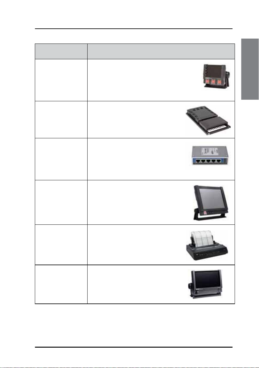
Accessory Description
Chapter 1: Introduction
SAILOR 6103
Multi Alarm Panel
SAILOR 6081
Power Supply Unit
and Charger
SAILOR 6197
Ethernet Switch
SAILOR 6006
Message Terminal
SAILOR H1252B
Printer
With the SAILOR 6103 Multi Alarm Panel
GMDSS Distress Alarms can be initiated and
monitored. The Multi Alarm Panel is
connected to the SAILOR 6300 MF/HF DSC
via the Ethernet interface (LAN connector).
The SAILOR 6081 Power Supply Unit
and Charger provides DC power and
automatically charges a connected
battery.
The SAILOR 6197 Ethernet Switch
can be used in installations with
SAILOR 6103 GMDSS Alarm Panels
and in installations with ThraneLINK.
The Ethernet switch has 5 ports.
Necessary for telex option. The
terminal is used for composing,
sending and receiving telex
Printing option for telex.
Introduction
SAILOR 6004
Control Panel
Used for future features and as a
DSC printing server.
Accessories available 7
Chapter 1: Introduction
TT-6209A
Accessory
Connection Box
TT-6209A
Accessory
Connection Box
DGNSS Receiver
TT-6588A
DGNSS Receiver
TT-6588A
Unit
Antenna Tuning
MF/HF
Handset
TT-638xA
Message Terminal
DSC Watch receiver
250W MF/HF with 6 ch. Scanning
TT-636xA
MF/HF DSC Telex Aerial
(Optional)
Keyboard
MF/HF Control Unit
TT-630xA
Alarm Panel
TT-6103A
Handset
GPS option
2182 select option
TT-6270A
Power Supply
TT-608xA
Connection Box
Control Unit
Distress Alarm
Other Alarm
TT-6201A
Transceiver Unit
TT-6201A
TT-6208A
TT-6001A
TT-6006A
(Optional)
Ethernet Switch
TT-6197A
GPS on LAN option
Optional connection
TT-6286A
DGNSS Antenna - Active
TT-6286A
DGNSS Antenna - Active
Telex option
Printer
H1252B
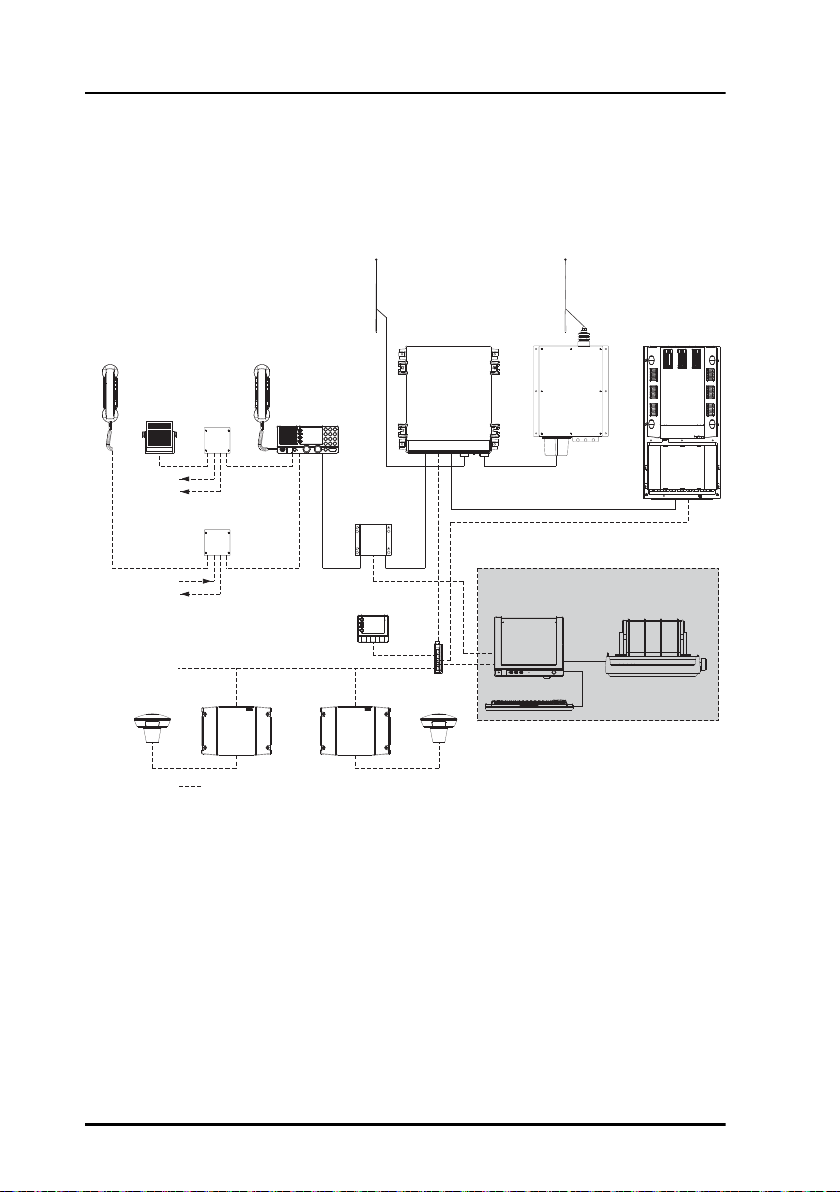
System configuration - examples
Transceiver TT-636xA and Antenna Tuning Unit TT-638xA
8 Accessories available

Chapter 1: Introduction
TT-6209A
Accessory
Connection Box
TT-6209A
Accessory
Connection Box
DGNSS Receiver
TT-6588A
DGNSS Receiver
TT-6588A
Unit
Antenna Tuning
Tx
Handset
TT-638xB
Message Terminal
DSC Watch receiver
250W MF/HF with 6 ch. Scanning
TT-636xB
(Optional)
Keyboard
MF/HF Control Unit
TT-630xA
Alarm Panel
TT- 6103A
Ethernet Switch
TT-6197A
Handset
GPS option
2182 select option
TT-6270A
Power Supply
TT-608xA
Connection Box
Control Unit
Distress Alarm
Other Alarm
TT-6201A
Transceiver Unit
TT-6201A
TT-6208A
TT-6001A
TT- 6006A
(Optional)
Rx
GPS on LAN option
Optional connection
TT-6286A
DGNSS Antenna - Active
TT-6286A
DGNSS Antenna - Active
Telex option
Printer
H1252B
Transceivers TT-636xB and Antenna Tuning Unit TT-638xB
Introduction
Accessories available 9

Chapter 1: Introduction
10 Accessories available
Chapter 2
Operation 2
Overview
In this chapter you find detailed instructions and guidelines for:
• General use and navigation
• Basic MF/HF radio communication
• Watch function
• DSC calls
• Handling multiple calls — DSC and voice
• Phone book
• Replay function
• Setup
General use and navigation
Operation
When the MF/HF radio is powered on for the first time, typically during
installation, the vessel’s MMSI number is entered. Hereafter the MMSI
number is briefly displayed after power up. The MMSI is a unique, 9-digit
identifier assigned to your ship.
Caution! Without a programmed MMSI number the
Distress button will not work!
The message NO DSC (NO MMSI) is shown in the DSC
window if the MMSI has not been programmed during
installation.
11

Chapter 2: Operation
Tune
Power on, speaker volume and antenna tuning
The MF/HF radio has a dual-function on/off knob for power
on/off and volume control.
Action Procedure
Power on Press the on/off knob.
Power off Press and hold the on/off knob and follow the
instructions in the display.
Speaker volume
Turn the volume knob (clockwise = louder,
counterclockwise = softer, until muted). When muted,
is shown in the display.
Volume of the
handset
earpiece
Tuning the
antenna unit
To adjust the volume of the handset earpiece see
Controller setup on page 50.
The radio tunes first time you press the
PTT button on a new frequency. As long
as the tuning symbol is in the display, the radio is not
transmitting. Wait until the tuning symbol has
disappeared before talking. Tuning may take from 0.1 s
to 8 s.
Tuning is automatically done
• after selection of a new frequency,
• after a four hour time out
12 General use and navigation
Chapter 2: Operation
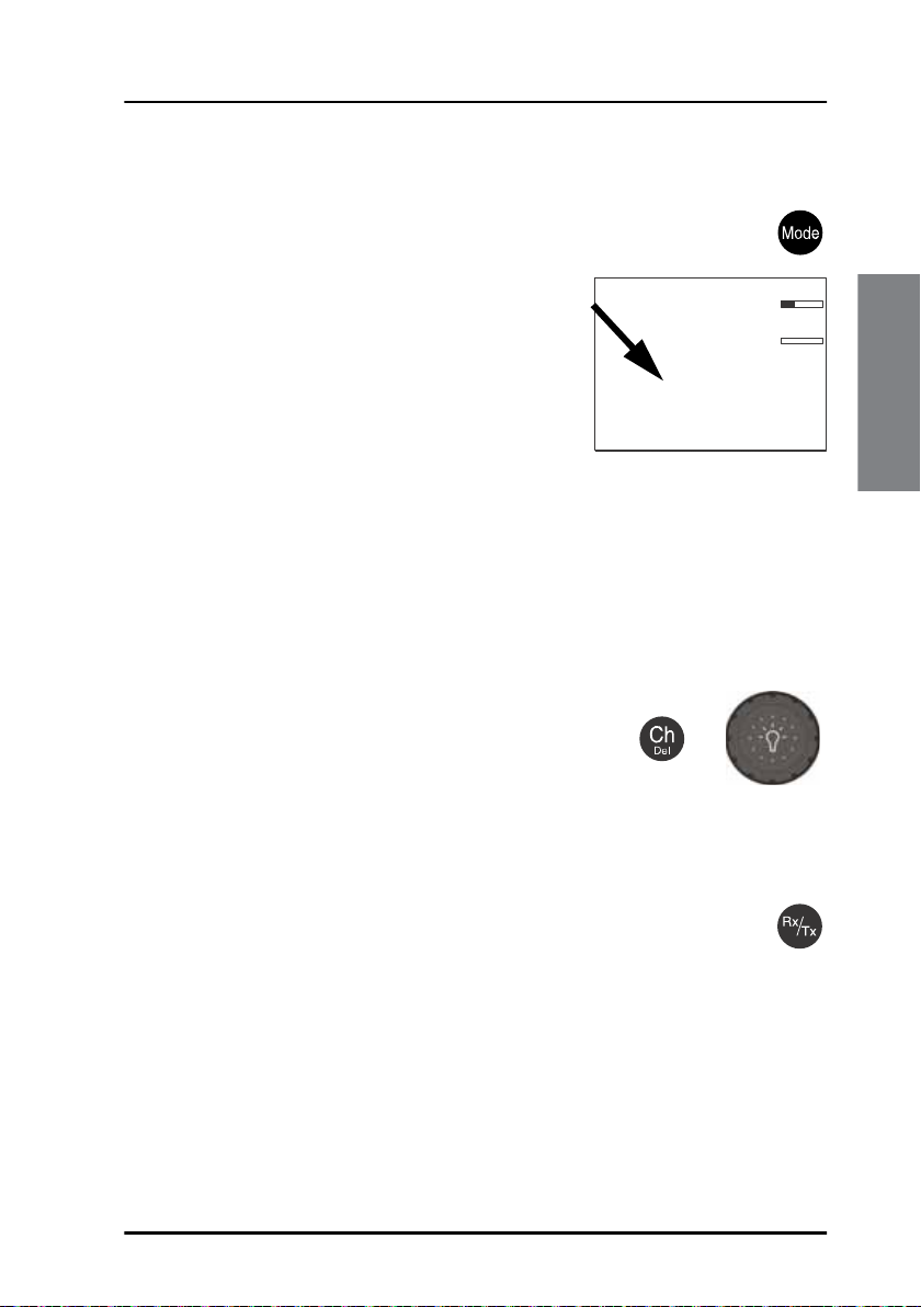
SSB, AM BROADCAST, DSC or TELEX mode
Press the Mode button to toggle between modes of the MF/HF
radio.
• SSB: Upper side band mode used for
standard MF/HF telephony.
• AM: AM broadcast is a listen-only mode for
pleasure purposes except for 2182kHz on
US equipment.
• LSB: Optional feature for listening to lower
side band
• DSC: The MF/HF radio monitors a single DSC channel to be able to
receive DSC calls.
• TLX-SHIP: The MF/HF radio monitors a single TELEX channel for telex
communication using a SAILOR 6006 Message Terminal.
CALL
ALERT
DROBOS
MORE
4357.0
4065.0
SSB 401
MMSI: 123456789
N 12°34.5678
E 123°45.6789
Radio settings and ITU channel selection
To select an ITU channel press the channel button
and
• turn the selector knob or
• press the numbers on the keypad.
+
Entering Rx and Tx frequencies
To enter RX and TX frequencies use the RX/TX button and the
keypad.
SQ
kHz/Rx
kHz/Tx
22:07
Operation
GPS
• First press on RX/TX button, enter Rx frequency and press OK.
• Press RX/TX button again to, enter Tx frequency and press OK to select
• Press and hold RX/TX button to enter simplex frequencies and press OK.
The same frequency is copied to both RX and TX fields on the radio.
General use and navigation 13
 Loading...