

COBHAM SAILOR 6210 VHF, SAILOR 6215 VHF, SAILOR 6222 VHF, SAILOR 6216 VHF, SAILOR 6248 VHF Installation Manual
...
SAILOR 6000 VHF Program
Installation manual
SAILOR 6210/6215/6216/6217 VHF
SAILOR 6222/6248/6249 VHF

Record of revisions
Rev. Description Release Date Initials
A Original document March 2012 CMA
B Installation Manual SAILOR 6217 added June 2012 CMA
Program 6000 VHF general - Controls on the front plate,
C
’Comments to prevent wter ingress’ added.
SAILOR 6222 VHF DSC - ’2.5.5 Setup of GPS input from LAN’ added
D Cobham rebranding November 2013 CMA
December 2012 CMA

SAILOR 6210 VHF
Installation manual
Release date: November 15, 2013

SAILOR 6210 VHF
Disclaimer
Any responsibility or liability for loss or damage in connection with the use of this product and the
accompanying documentation is disclaimed by Thrane & Thrane A/S. The information in this manual is
provided for information purposes only, is subject to change without notice and may contain errors or
inaccuracies. Manuals issued by Thrane & Thrane A/S are periodically revised and updated. Anyone
relying on this information should acquire the most current version e.g. from www.cobham.com/satcom
or from the distributor. Thrane & Thrane A/S is not responsible for the content or accuracy of any
translations or reproductions, in whole or in part, of this manual from any other source.
Thrane & Thrane A/S is trading as Cobham SATCOM.
Copyright
© 2013 Thrane & Thrane A/S. All rights reserved. Printed in Denmark.
Trademark Acknowledgements
• SAILOR is a registered trademarks of Thrane & Thrane A/S.
• Other product and company names mentioned in this manual may be trademarks or trade names of
their respective owners.
ii

SAILOR 6210 VHF
Safety warning
The following general safety precautions must be observed during all phases of operation,
service and repair of this equipment. Failure to comply with these precautions or with specific
warnings elsewhere in this manual violates safety standards of design, manufacture and
intended use of the equipment. Thrane & Thrane assumes no liability for the customer's failure
to comply with these requirements.
RF exposure hazards and instructions
Your Thrane & Thrane radio set generates electromagnetic RF (radio frequency) energy when
transmitting. To ensure that you and those around you are not exposed to excessive amounts
of energy and thus to avoid health hazards from excessive exposure to RF energy, all persons
must be at least 3ft (0.9 m) away from the antenna when the radio is transmitting.
Warranty limitation
IMPORTANT - The radio is a sealed waterproof unit (classified IPX8). To create and maintain its
waterproof integrity it was assembled in a controlled environment using special equipment. The
radio is not a user maintainable unit, and under no circumstances should the unit be opened
except by authorized personnel. Unauthorized opening of the unit will invalidate the warranty.
Installation and service
Installation and general service must be done by skilled service personnel.
iii

SAILOR 6210 VHF
Manual overview
This manual has the following chapters:
• Introduction contains a description of the VHF radio.
• Installation explains how to mount the VHF radio and how to connect accessories and external
equipment.
• First-time power up explains how to make and receive voice calls over VHF, including how to use and
set-up the channel scanning, the 2-way loudhailer, fog horn external loudspeaker.
• Service & maintenance contains support information including lists of accessories and a
troubleshooting guide.
Appendices with Technical specifications and System configurations.
iv

SAILOR 6210 VHF Table of Contents
Table of Contents
Chapter 1 Introduction
1.1 VHF radio ................................................................................................................................1-1
1.2 Accessories available .....................................................................................................1-4
Chapter 2 Installation
2.1 Unpacking the SAILOR 6210 VHF .......................................................................2-7
2.2 Installing the VHF radio ..............................................................................................2-8
2.3 Power, VHF antenna and external equipment ........................................2-15
2.4 VHF antenna installation .........................................................................................2-22
2.5 System setup ....................................................................................................................2-24
2.6 SAILOR 6201 Handset cradle (optional) ......................................................2-24
2.7 Accessories .........................................................................................................................2-25
Chapter 3 First-time power up
3.1 General use and navigation ...................................................................................3-31
Chapter 4 Service & maintenance
4.1 Contact for support .....................................................................................................4-33
4.2 Maintenance ......................................................................................................................4-33
4.3 Returning units for repair ........................................................................................4-36
Appendix A Technical specifications
A.1 SAILOR 6210 VHF ........................................................................................................ A-37
Appendix B System configurations
B.1 System configuration examples ........................................................................B-39
B.2 Cable requirements ......................................................................................................B-43
Glossary ...........................................................................................................................................................Glossary-47
Index ................................................................................................................................................................ Index-49
v

Table of Contents SAILOR 6210 VHF
vi

SAILOR 6210 VHF
List of figures
Figure 1-1: Controls on the front plate...........................................................................................................................1-2
Figure 1-2: System configuration - example................................................................................................................1-6
Figure 2-1: Desktop mounting ............................................................................................................................................2-9
Figure 2-2: Overhead mounting .........................................................................................................................................2-9
Figure 2-3: Mounting with U mounting bracket...................................................................................................... 2-10
Figure 2-4: Flush mount ......................................................................................................................................................2-11
Figure 2-5: Cutout for flush mount................................................................................................................................ 2-11
Figure 2-6: Flush mount details .......................................................................................................................................2-12
Figure 2-7: SAILOR 6090 Power Converter, dimensions.....................................................................................2-13
Figure 2-8: Connecting the SAILOR 6090 Power Converter .............................................................................2-13
Figure 2-9: Handmicrophone............................................................................................................................................ 2-14
Figure 2-10: Power, VHF antenna and external equipment..................................................................................2-15
Figure 2-11: External DSC controller ...............................................................................................................................2-16
Figure 2-12: NMEA interface description...................................................................................................................... 2-17
Figure 2-13: Power, loudhailer, foghorn and external speaker............................................................................2-20
Figure 2-14: Protection against water ingress.............................................................................................................2-20
Figure 2-15: Ground stud.......................................................................................................................................................2-21
Figure 2-16: Antenna positioning......................................................................................................................................2-23
Figure 2-17: Antenna positioning 1/2 .............................................................................................................................2-23
Figure 2-18: Handset. ..............................................................................................................................................................2-24
Figure 2-19: SAILOR 6207 Connection Box for parallel handsets, mounting.............................................. 2-26
Figure 2-20: Connection Box for parallel handsets, wiring ...................................................................................2-26
Figure 2-21: SAILOR 6207 Connection Box for parallel handsets, diagram .................................................2-27
Figure 2-22: SAILOR 6208 Control Unit Connection Box, mounting ..............................................................2-28
Figure 2-23: SAILOR 6208 Control Unit Connection Box for parallel handsets, wiring..........................2-28
Figure 2-24: SAILOR 6208 Control Unit Connection Box, diagram..................................................................2-29
Figure 4-1: Fuse in the SAILOR 6090 Power Converter.......................................................................................4-35
Figure B-1: How to install a SAILOR 6204 CSM far from the VHF..................................................................B-40
Figure B-2: How to install a SAILOR 6204 close to the VHF radio..................................................................B-41
Figure B-3: How to install a SAILOR 6204 very close to the VHF radio .......................................................B-42
vii

SAILOR 6210 VHF
viii

SAILOR 6210 VHF
List of tables
Table 1-1: Accessories available .......................................................................................................................................1-4
Table 2-1: Compass safe distance ...................................................................................................................................2-8
Table 2-2: ACC connector ................................................................................................................................................2-16
Table 2-3: NMEA interface............................................................................................................................................... 2-17
Table 2-4: CTRL connector for control speaker microphone ..........................................................................2-19
Table 2-5: System setup .................................................................................................................................................... 2-24
Table 2-6: Part numbers for accessories....................................................................................................................2-25
Table 4-1: Troubleshooting guide................................................................................................................................. 4-33
Table A-1: Technical specifications..............................................................................................................................A-37
Table B-1: Cable overview ................................................................................................................................................B-43
Table B-2: Cable specifications for cable 2...............................................................................................................B-44
Table B-3: Cable specifications for cable 8 (CTRL) ...............................................................................................B-44
ix

SAILOR 6210 VHF
x
Chapter 1
Introduction 1
1111
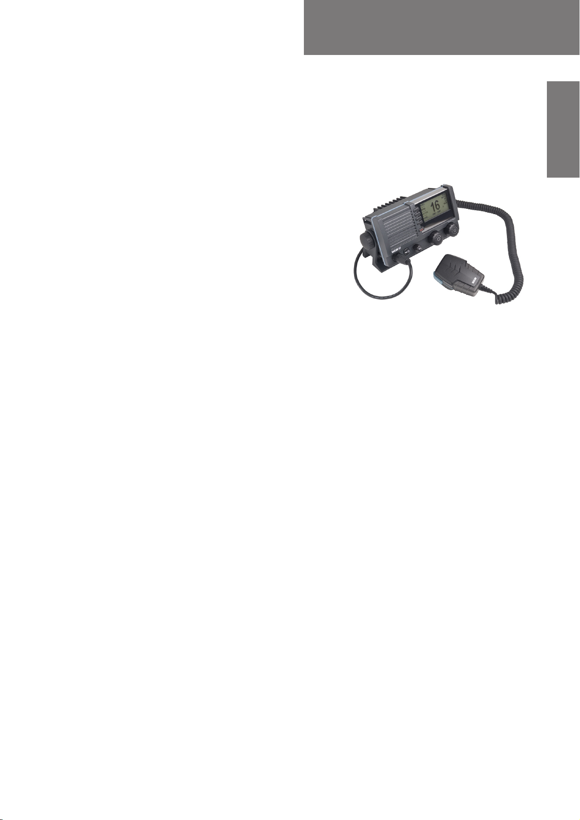
1.1 VHF radio
SAILOR 6210 VHF is approved to R&TTE and is
waterproof to the IPx8 and IPx6 standard. As
part of the safety equipment, use the SAILOR
6210 VHF in an emergency situation. However
the best way to guarantee functionality in an
emergency situation, is to use the radio in daily
communication on board.
The VHF radio is a simplex/semi duplex VHF
radio. It is designed with an easy-to-use menudriven setup. You use the soft-keys to enter the
desired functions, you browse and select a
setting using the right selection wheel knob. The large display has red adjustable backlight
which provides a good visibility even at night and protects your night vision.
The VHF radio can replay the last 90 s of received voice. This is a useful feature to minimize
misunderstandings and to record messages when the radio is unattended.
The VHF radio connects easily to external equipment like a 2-way loudhailer and an
external speaker. You can use the loudhailer as a 2-way on-board communicator. The
loudhailer also functions as a fog horn. You can select from several programmed fog-horn
patterns.
Introduction
For a list of other accessories available for the SAILOR 6210 VHF check with your nearest
distributor.
1-1
VHF radio SAILOR 6210 VHF
1
23
4
5
HI/LO
WATCH
SCAN
INT
DUAL WATCH
SHIP - SHIP
16
MORE...
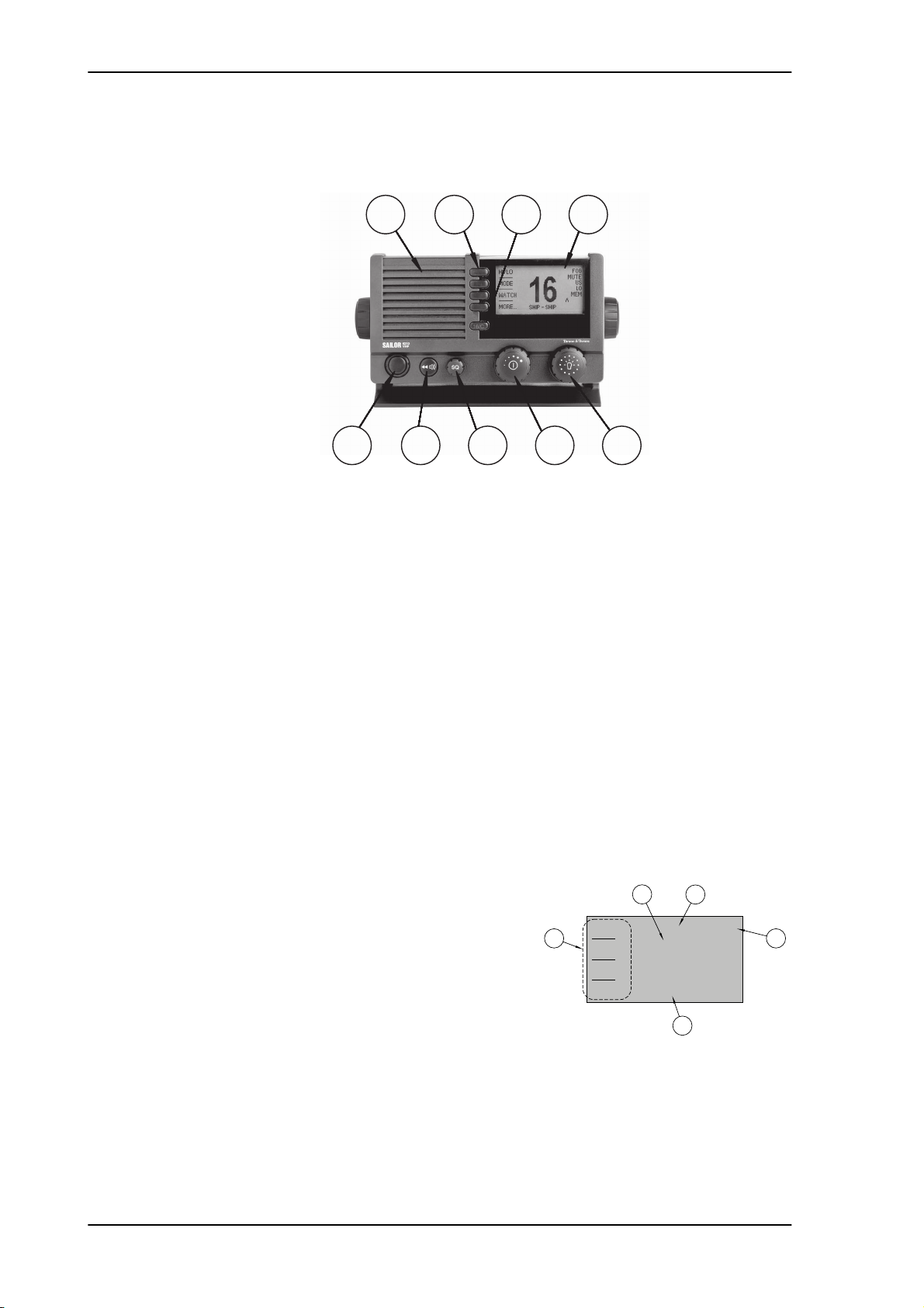
Controls on the front plate
1
5
Figure 1-1: Controls on the front plate
2
7
3 4
6 8 9
1. Loudspeaker.
2. Four soft keys with function title in the display.
3. Quick selection key for channel 16 and the programmed call channel.
4. Large display.
5. Connector for Handmicrophone or handset. If not used, put the cap from the ACC
connector on the front connector to prevent water ingress.
6. Squelch control to mute background noise.
7. Replay button to play back up to 90 s voice message.
8. Volume wheel knob with key-press function for volume control and power on/off.
9. Selector wheel knob with key-press function for changing the working channel,
navigating in menus in the display and backlight dimming.
1.1.1 SAILOR 6210 VHF display
The picture shows the display after start-up.The
display holds various fields of information,
depending on the currently selected function.
1. Current working channel.
2. Functions you can select with the soft keys. If
there are more than 4 functions in the list press
the soft key MORE to display further functions.
3. Status and other values for the current state or
VHF channel.
4. Service line containing current temporary information relevant for the current channel
or function.
5. Action line containing current state or temporary information relevant for the
currently selected function.
1-2 Chapter 1: Introduction

SAILOR 6210 VHF VHF radio
For a detailed description of the information shown for each of the functions available see
the chapter First-time power up on page 3-31.
1111
Introduction
Chapter 1: Introduction 1-3
Accessories available SAILOR 6210 VHF
1.2 Accessories available
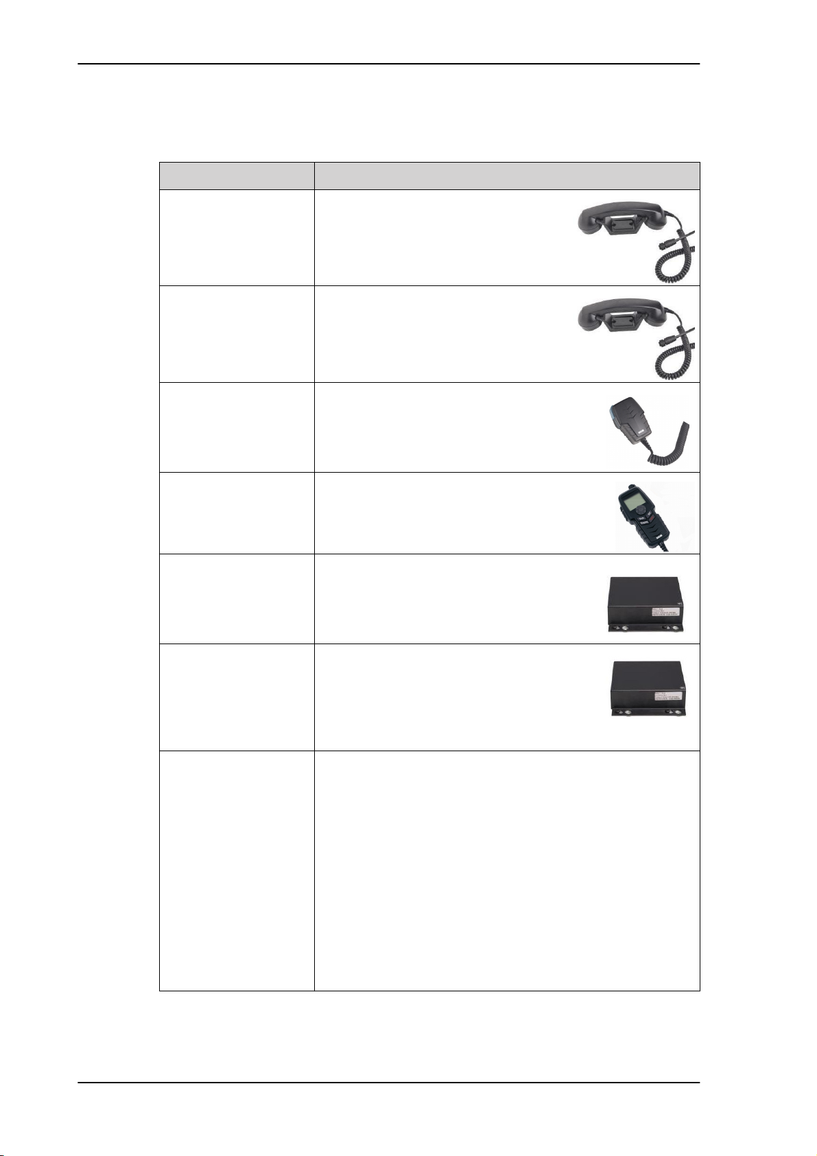
Accessory Description
SAILOR 6201 Handset
with cradle (additional)
SAILOR 6203 Handset
with cradle
SAILOR 6202 Hand
Microphone
SAILOR 6204 Control
Speaker Microphone
SAILOR 6207
Connection Box for
parallel handsets
One SAILOR 6201 Handset with cradle is
included in the delivery of the SAILOR
6210 VHF. You can connect another 2
SAILOR 6201 Handsets.
SAILOR 6203 Handset with cradle,
waterproof to IPx6.
You can use the SAILOR 6202 (waterproof to
IPx6 and IPx8) Hand Microphone instead of
the handset.
With the SAILOR 6204 Control Speaker
Microphone you can control the VHF
functions of the SAILOR 6210 VHF.
The SAILOR 6207 Connection Box including
Connection Cable 406209-941 is used for
easy installation of several SAILOR 6201/03
Handsets/SAILOR 6202 Hand Microphones.
SAILOR 6208 Control
Unit Connection Box
Connection cables 5m connection cable for bulkhead mount: Use this cable
The SAILOR 6208 Connection Box including
Connection Cable 406208-941 is used for easy
installation of external equipment and
accessories:
• Max. 1 SAILOR 6204 Control Speaker Microphones
in installations where the SAILOR 6202 Hand Microphone is
not connected directly to the SAILOR 6210 VHF, but located
in a different position (part number: 406209-940).
5m Connection cable, 1x10 pole: Use this cable in
installations when connecting external equipment to the
SAILOR 6210 VHF. This cable is included in the SAILOR 6207
Connection Box for parallel handsets (part number: 406209-
941).
5 m Connection cable for SAILOR 6204 Control
Speaker Microphone, 1x12 pole (part number: 406204-
940).
Table 1-1: Accessories available
1-4 Chapter 1: Introduction

SAILOR 6210 VHF Accessories available
Accessory Description
1111
SAILOR 6270 External
loudspeaker
SAILOR 6090 Power
Converter 24 V to
12 V DC
If you need an additional external loudspeaker
you can connect a SAILOR 6270 Loudspeaker.
It provides 6 W output power.
Introduction
The SAILOR 6090 Power Converter is used
to provide 12 V DC for the SAILOR 6210
VHF from a 24 V DC power source.
Table 1-1: Accessories available (Continued)
Chapter 1: Introduction 1-5
Accessories available SAILOR 6210 VHF
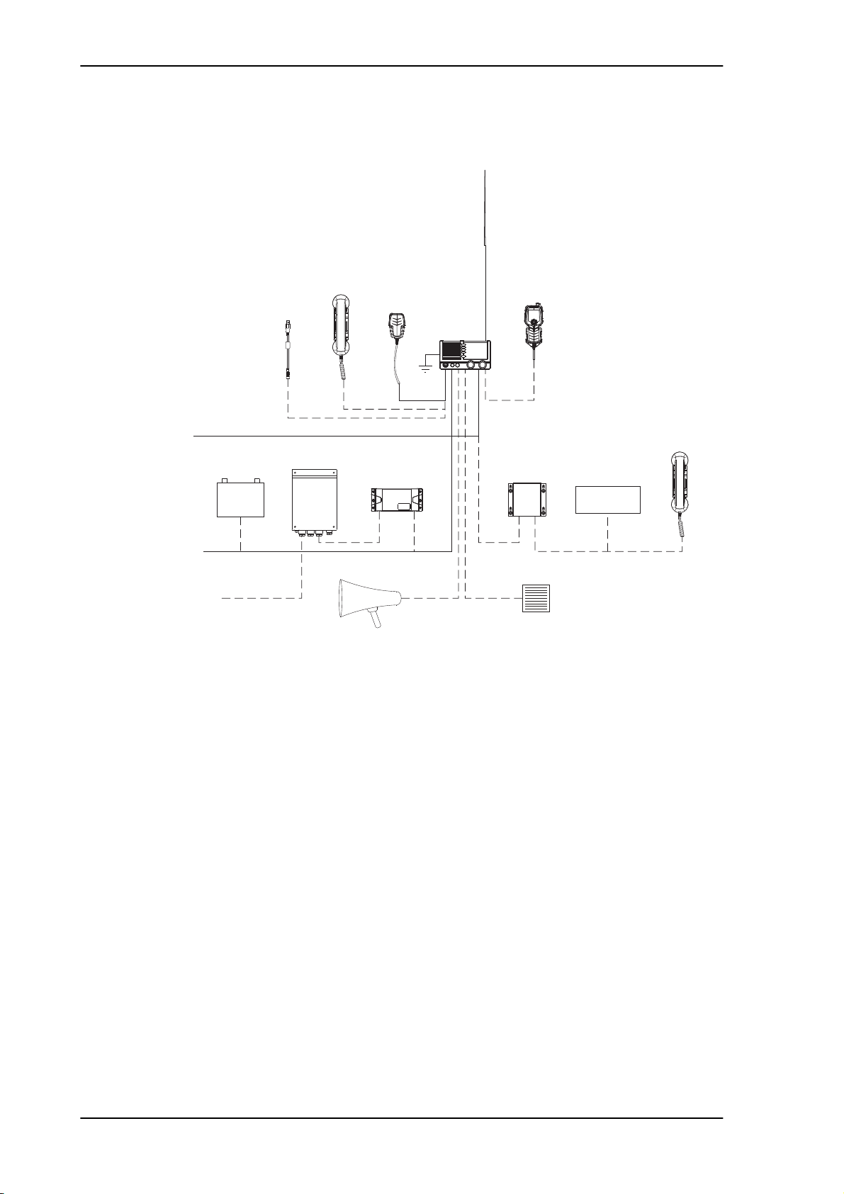
Handset
Microphone
DSC modem
Cable
Service
Loud Hailer (4 ohm)
Speaker (8 ohm)
External
ACC. Port
Power
Handset Option
SAILOR 6204
SAILOR 6201
SAILOR 6201
Hand Microphone
SAILOR 6202
12V DC
110/220V AC
GPS
External
Control Speaker
SAILOR 6207
Connection Box
for parallel handsets
VHF
SAILOR 6210
99-130265-B
N163S
Aerial
RX/TX
SAILOR 6090
12V Battery
24V DC
Power Converter
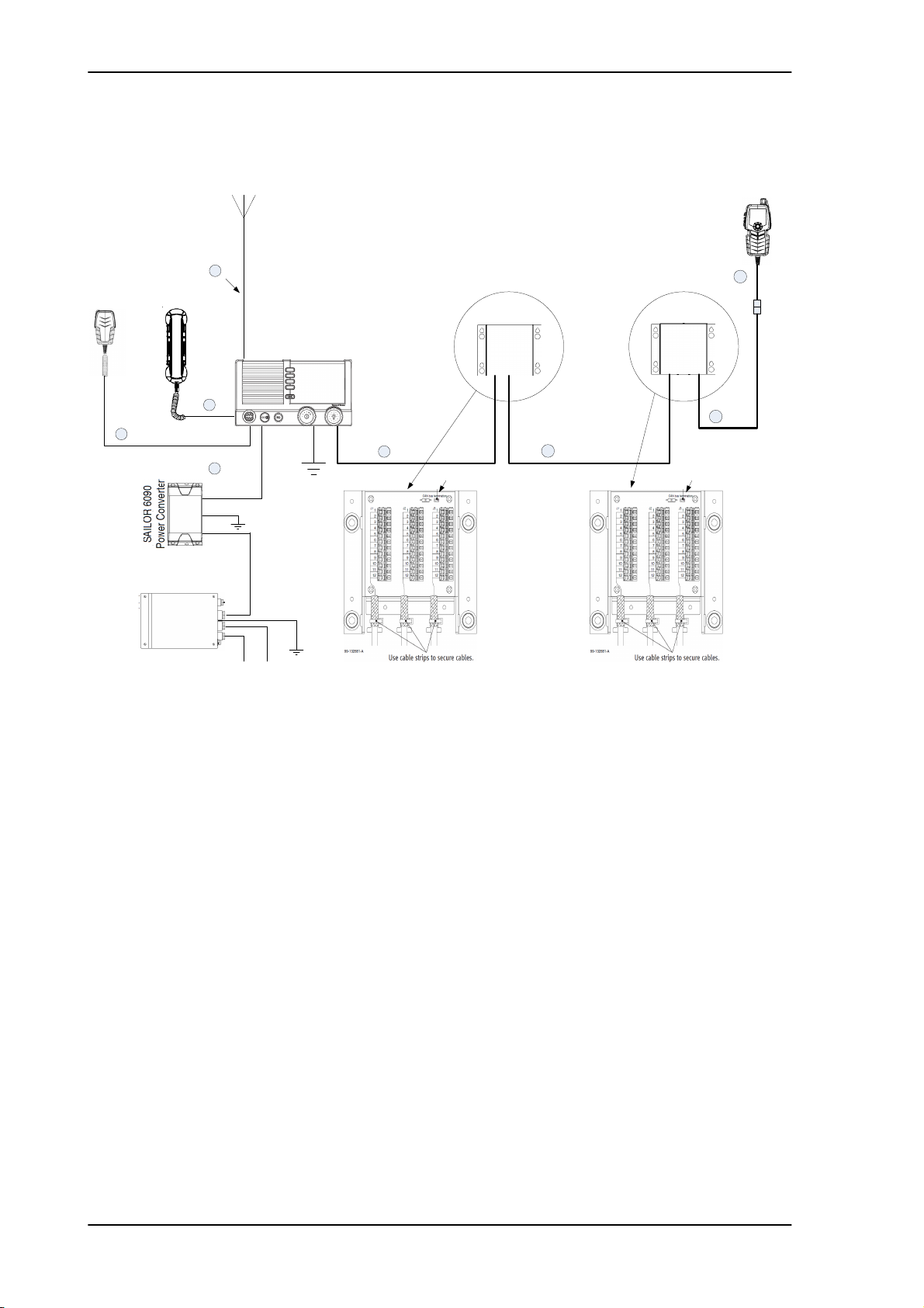
1.2.1 System configuration - example
Figure 1-2: System configuration - example
1-6 Chapter 1: Introduction

Chapter 2
Installation 2
In this chapter you find information and guidelines for:
• Unpacking the SAILOR 6210 VHF
• Installing the VHF radio
2222
• Power, VHF antenna and external equipment
2.1 Unpacking the SAILOR 6210 VHF
The following items are included in the delivery of a SAILOR 6210 VHF:
• SAILOR 6210 VHF
• SAILOR 6202 Handmicrophone with spiral cable
• User and installation manual
• Installation guide
• Mounting bracket with two wheel knobs
• Connectors for cables
• Power cables, fittings and fuses
• Packaging material
• Sun screen (click-on) for front plate protection
• Kit for flush mount installation, including gasket
Installation
2-7
Installing the VHF radio SAILOR 6210 VHF
2.2 Installing the VHF radio
You can mount the VHF radio as a desktop, overhead or flush-mounted unit integrated in
the instrument panel.
Provide space enough to access the front panel connectors and for installing a cradle for
the speaking device.
Provide at least 120 mm space at the back of the SAILOR 6210 VHF radio to allow free
air circulation.
Compass safe distance
Make sure that the VHF radio is far enough from any magnetic compass to avoid influence
of the loudspeaker magnet on the compass reading. See the following table for the safe
distance after magnetization between the nearest point of the device and the centre of the
compass at which it will produce a deviation of 0.3°.
Device Safe distance
SAILOR 6210 VHF 1.0 m
SAILOR 6202 Handmicrophone 0.8 m
SAILOR 6090 Power Converter 24 V - 12 V 0,15 m
SAILOR 6207 Connection Box for parallel handsets 0.6 m
SAILOR 6208 Control Unit Connection Box 0.6 m
Table 2-1: Compass safe distance
2-8 Chapter 2: Installation
SAILOR 6210 VHF Installing the VHF radio
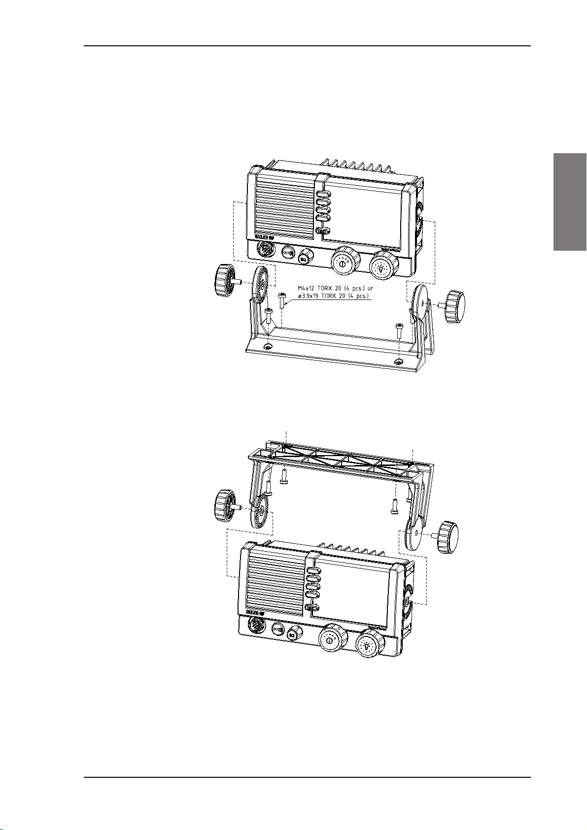
2.2.1 SAILOR 6210 VHF with U mounting bracket
The mounting bracket and two knobs are included in the delivery.
Desktop mounting
2222
Installation
Overhead mounting
Figure 2-1: Desktop mounting
Figure 2-2: Overhead mounting
Chapter 2: Installation 2-9
Installing the VHF radio SAILOR 6210 VHF
99-130249
4 x M4 or hole for
self-tapping ø3.9
150mm
53mm
71mm
196mm
23mm
9mm
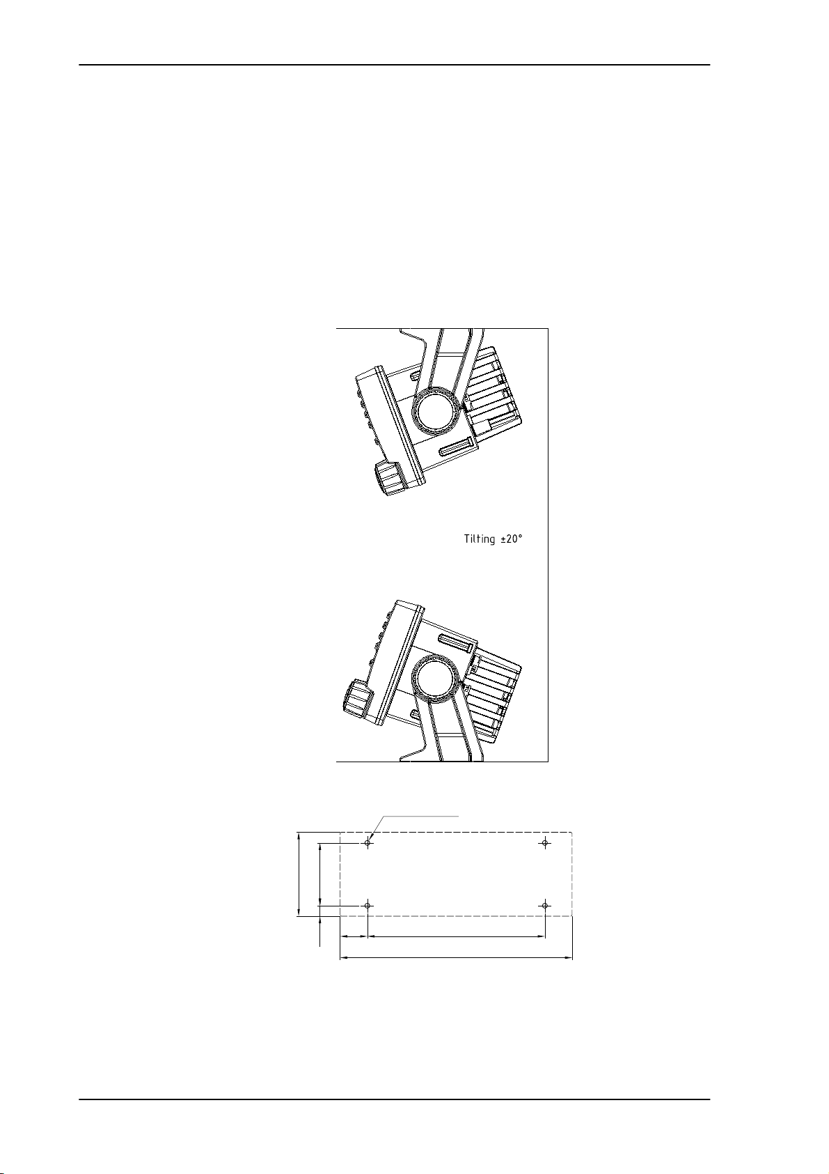
Mounting with U mounting bracket
To mount the VHF radio as tabletop, do as follows:
1. Find a suitable location for the VHF radio. Check that the space is wide/deep enough to
accommodate the VHF radio.
2. Fasten the bracket with 4 screws (included in the delivery.)
3. Insert the VHF radio in the bracket and fasten it with the two knobs.
4. The display of the VHF radio should be at an angle of approximately 90° to your line of
sight when operating it.
2-10 Chapter 2: Installation
Figure 2-3: Mounting with U mounting bracket
SAILOR 6210 VHF Installing the VHF radio
Remove material from shaded area only!
89mm
177mm
R2.5mm x 4
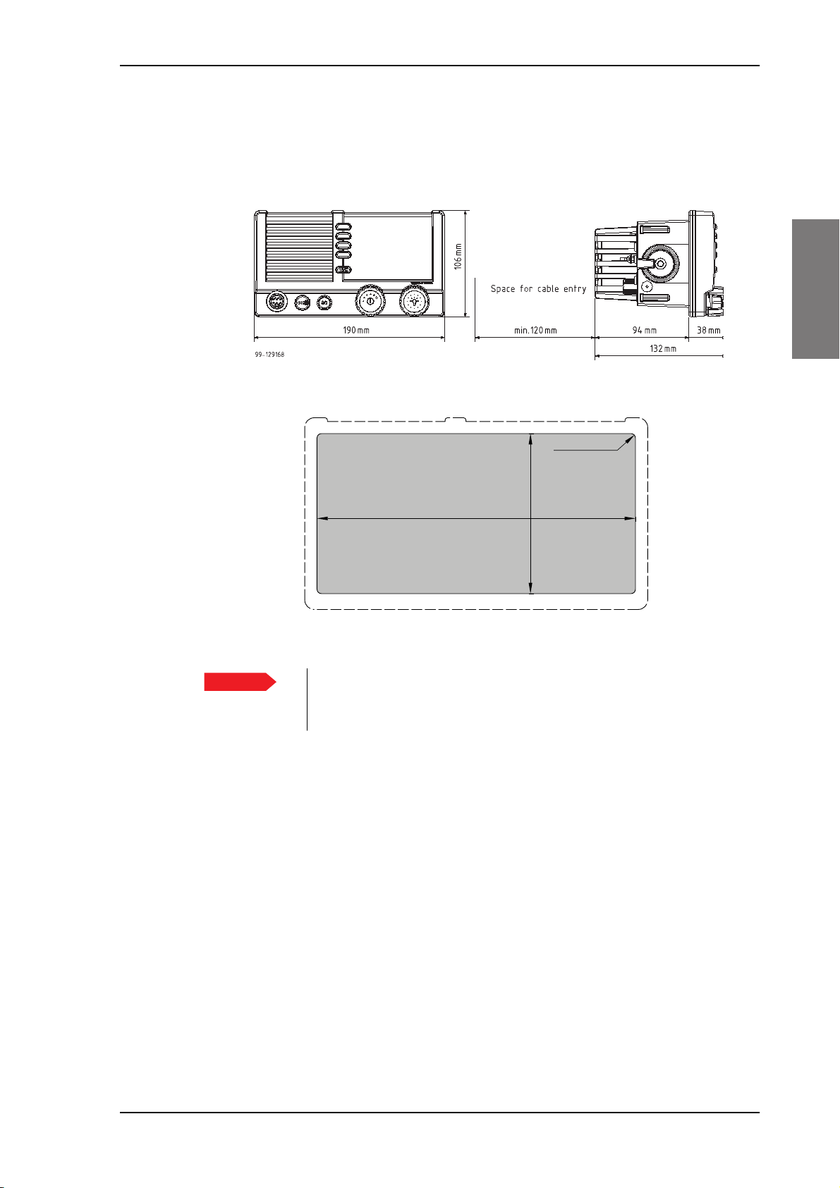
2.2.2 SAILOR 6210 VHF for flush mount
You can mount the VHF radio to a flat surface, e.g. an instrument panel.The flush mount
installation kit is included in the delivery.
Figure 2-4: Flush mount
2222
Installation
Figure 2-5: Cutout for flush mount
Important
1. Find a suitable location for the VHF radio. Check that the space is deep enough to
accommodate the VHF radio and an additional min. 120 mm space for cable entry.
2. Keep free distance to allow free air circulation around the VHF radio and to allow
sufficient space for access to cables, see the drawing on this page.
3. Cut out the hole for the VHF radio where you want to mount it. Use the cutting template
in the installation guide.
4. Mount the 4 square nuts M4 in the cabinet, ensure that they are placed correctly so it is
possible to screw in the M4x45 screws.
5. Ensure that the flush mount gasket is placed correctly on the VHF radio.
6. Before mounting the VHF radio be aware that the surface is plane and rigid. If the
surface is not plane and/or rigid (stiff) remove the gasket and seal with silicone sealant
between the VHF radio and the surface.
The scaling in the above drawing is not 1:1. Consequently do not
attempt to use a print or copy of this page without checking the
dimensions.
Chapter 2: Installation 2-11
Installing the VHF radio SAILOR 6210 VHF
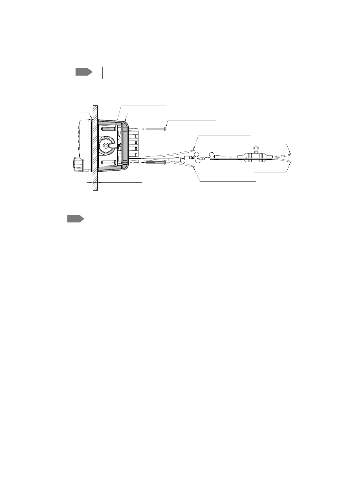
A
A
BB
99-130248
Gasket
Flush Mount Bracket (2 pcs.)
Screw M4x45 TORX 20 (4 pcs.)
Connect to LOUD HAILER
(RED isolation on inner connector)
Connect to EXT. SPEAKER
(WHITE isolation on inner connector)
Connect to POWER +
(RED wire)
Connect to POWER -
(BLUE wire)
Square Nut M4x7x2.2 (4 pcs.)
Max wall thickness 26mm
7. Slide the VHF radio in the cut-out. Place the flush mount bracket and fasten it with the 4
screws M4x45. Make sure the torque does not exceed 1Nm when fastening the screws.
Note
Note
Only use screws supplied with the kit for flush mounting.
Figure 2-6: Flush mount details
Firmly tie back and secure any wires not used to avoid the possibility for mutual
shorting or shorting to ground.
2-12 Chapter 2: Installation
SAILOR 6210 VHF Installing the VHF radio
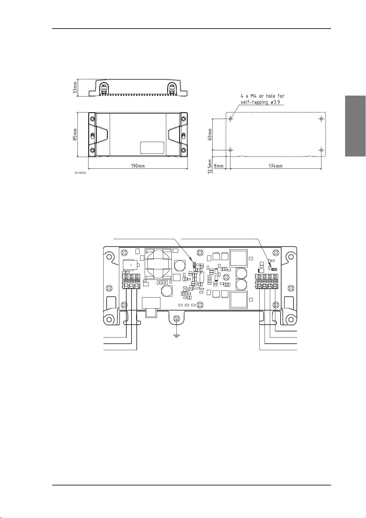
+
+
+
+
99-133089
Ground
24V DC
12V DC
-Vout
+Vin
-Vin
Screen/Ground
NC
NC
+Vout
Remove jumper W301:
Vout = 12.5V
Place jumper W300:
Power Converter is always on
H200
Q304
Q302
Q306
CR301
CR300
R314
W301
W300
CR302
C320 C306
C303
C304
C305
C307
C301
C321
C308
C315
C319
C316
C312
C208
C209
C322
C323
C205
C200
C210
C314
C309
C318
L200
C310
C317
C203
C204
VR301
CR305
VR300
CR303
VR302
R204
R203
R202
R201
R208 R207 R206
Q305
Q303
Q301
Q300
T200
C207
C206
C202
C201
C313
C302
J300
J200
C311
C300
CR200
L300
L301
U300
R338
R337
R336
R335
R334
R328
R329
R330
R331
R333
R332
R327
R326
R325
R324
R313
R307
R320
R309
R310
R312
R319
R300
R305
R302
R304
R306
R301
R303
R317
R316
R308
R311
R321
R322
R323
2.2.3 SAILOR 6090 Power Converter
2222
Installation
Figure 2-7: SAILOR 6090 Power Converter, dimensions
Figure 2-8: Connecting the SAILOR 6090 Power Converter
Chapter 2: Installation 2-13
Installing the VHF radio SAILOR 6210 VHF
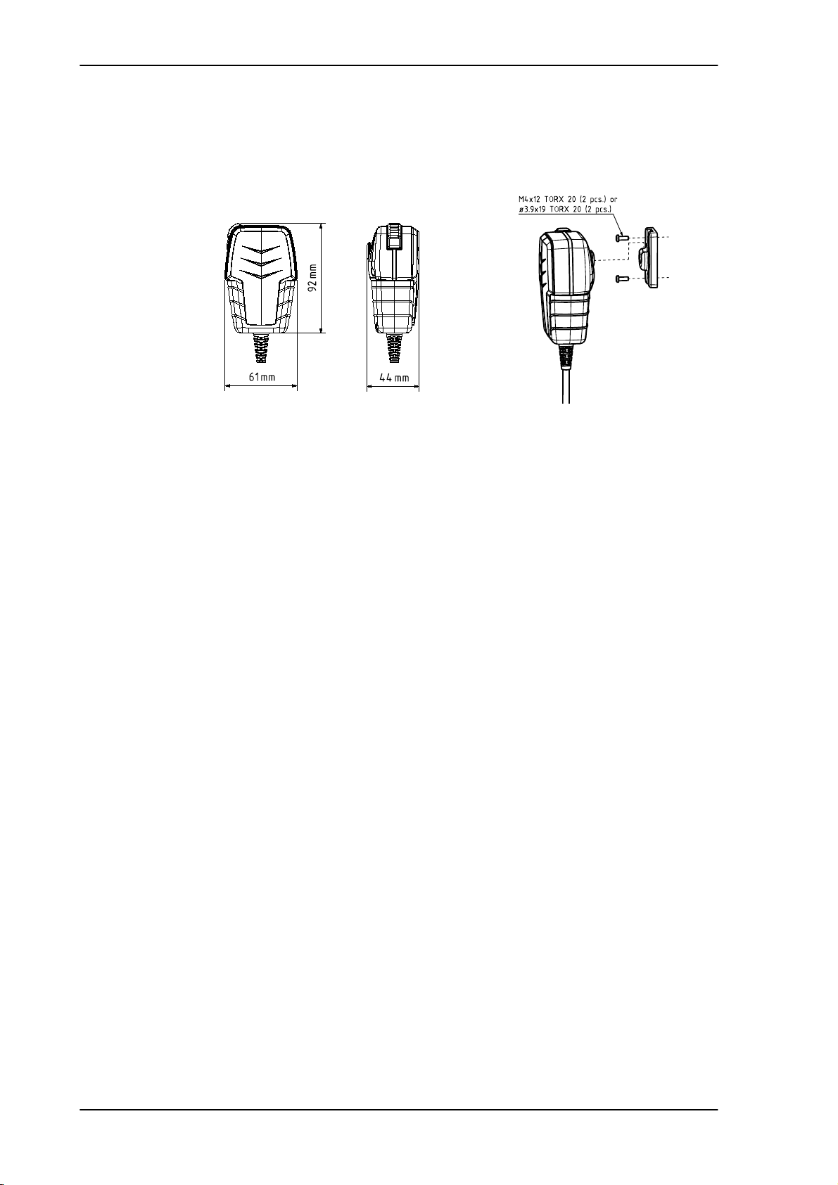
2.2.4 SAILOR 6202 Handmicrophone
Handmicrophone with spiral cable and PTT button.
Figure 2-9: Handmicrophone
2-14 Chapter 2: Installation
SAILOR 6210 VHF Power, VHF antenna and external equipment
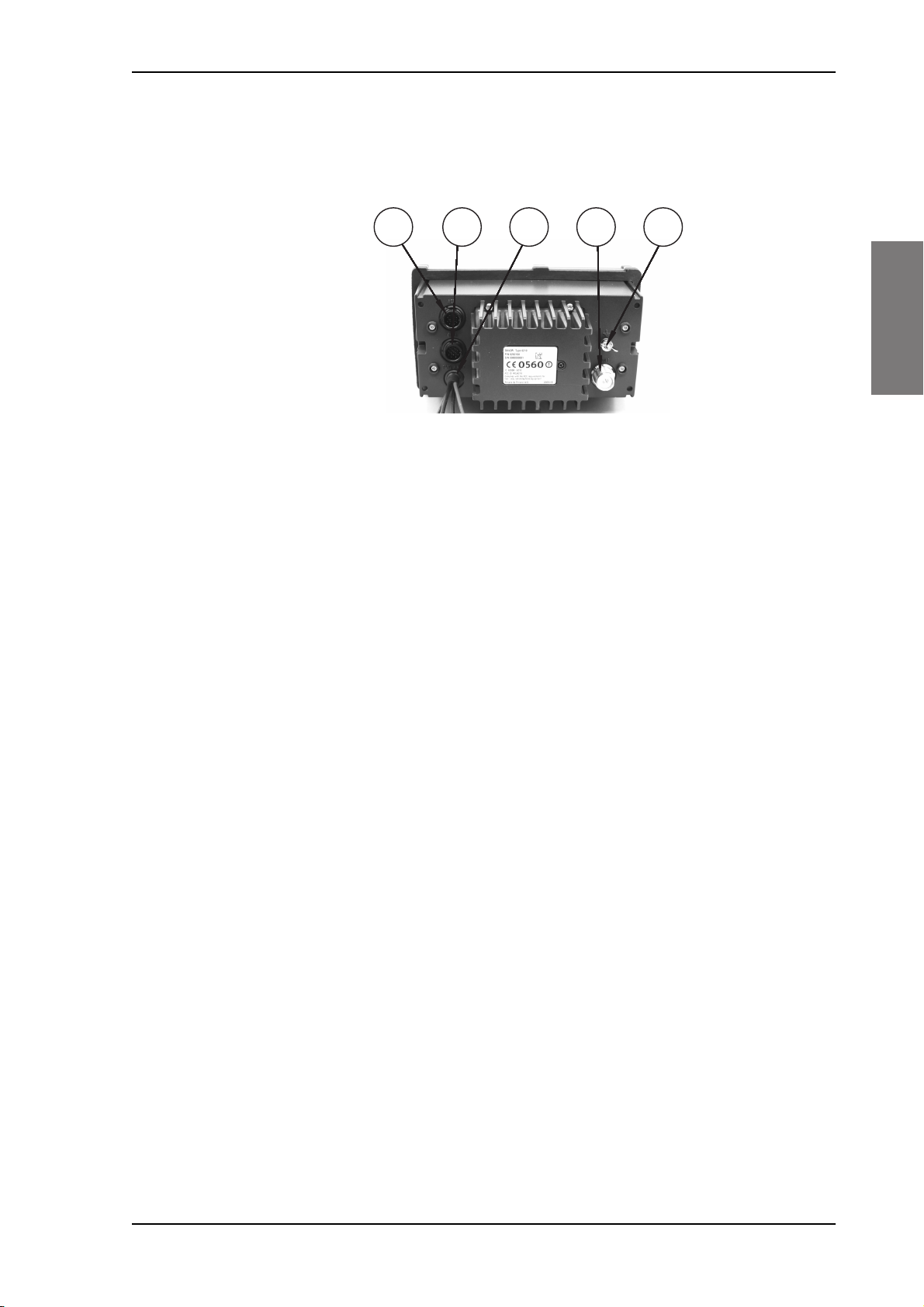
2.3 Power, VHF antenna and external equipment
2222
1
Figure 2-10: Power, VHF antenna and external equipment
1. ACC connector for accessories
2. CTRL connector for control speaker microphone
3. Power, Loudhailer, foghorn and external speaker
4. VHF antenna
5. Ground stud
2
3 4 5
Installation
Chapter 2: Installation 2-15
Power, VHF antenna and external equipment SAILOR 6210 VHF
1
2
341056
789
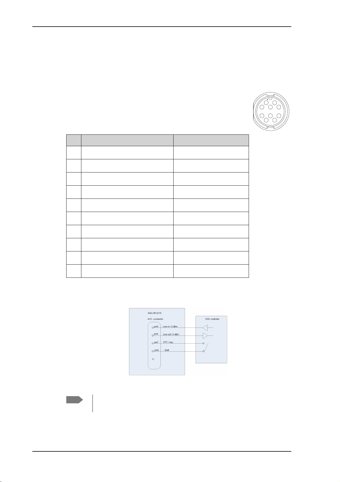
2.3.1 ACC connector
Use the connector marked ACC to connect GPS input.
The interface for GPS is NMEA 0183 (EN61 162-1 NMEA0183/ EN61 162-2 NMEA0183
Highspeed).
Connector type: Circular connector, 10pin.
Connection cable with plug, part number 406209-941.
Pin assignment: Connector front view on the VHF radio.
Pin Description Wire color
1 NMEA in+ Brown
2 NMEA in- Blue
3 NMEA out- White
4 NMEA out+ Green
5 Mike 2 / Line in Yellow
6 EAR 2 / Line out Grey
7 Hook_PTT Pink
8 Battery supply when radio is on Red
9 Internal GND = - Battery Black
10 Internal GND = - Battery Orange — SCREEN (Drain)
Table 2-2: ACC connector
External DSC controller
Figure 2-11: External DSC controller
Note
To achieve the 0dBm signal level on the Line Out pin the Handset 2 earpiece
volume must be configured to level 14 (max).
2-16 Chapter 2: Installation
SAILOR 6210 VHF Power, VHF antenna and external equipment
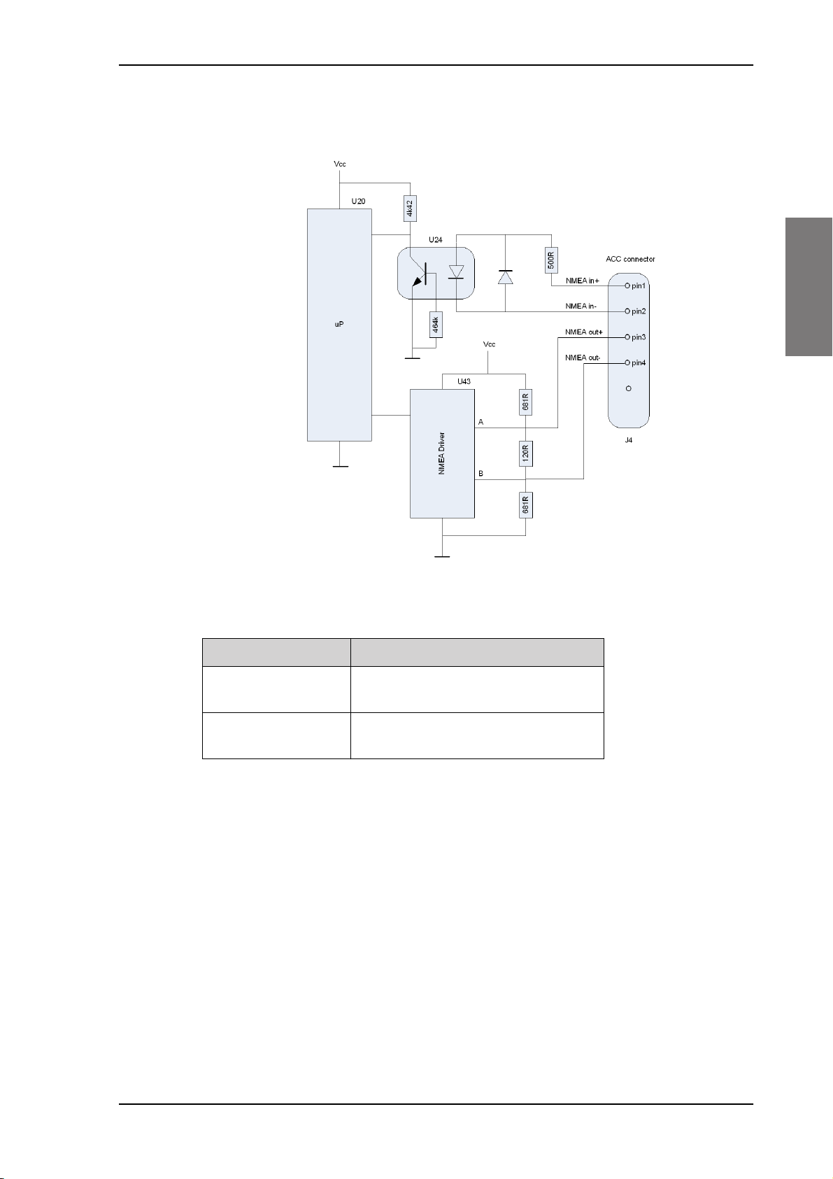
NMEA interface description
2222
Installation
Figure 2-12: NMEA interface description
NMEA interface Specifications
NMEA input:
NMEA output
The NMEA interface supports NMEA 0183 v2.0, v2.1 and v2.3.
The following sentences are supported:
• FSI: All fields are decoded.
• GGA: UTC, "Position", "quality indicator" (indicators 1-5). All other fields are unused.
• GLL: UTC, "Position", "Status" and "mode" (indicators A and D). All other fields are unused.
• GNS: UTC, "Position" and "mode" (indicators A and D). All other fields are unused.
• RMC: UTC, "Position", "Status", "Date" and "mode" (indicators A and D). All other fields are
unused.
Impedance: 600 Ohm
Max. 2mA at min. level of 2V
Load Impedance: > 60 Ohm
Drive load: < 35 mA
Table 2-3: NMEA interface
• ZDA: UTC, "Day", "Month", and "Year". All other fields are unused.
In accordance with the standard EN61162-1:2008 and EN61162-2:1998
Chapter 2: Installation 2-17

Power, VHF antenna and external equipment SAILOR 6210 VHF
Received NMEA sentences except for FSI can be forwarded to NMEA output. As talker the
sentences are streamed when received (with no intervals).
HW revision: 57-127367-D.02
SW revision: 2.00.01
2-18 Chapter 2: Installation

SAILOR 6210 VHF Power, VHF antenna and external equipment
1
2
11
3410
12
5
6
789
2.3.2 CTRL connector for control speaker microphone
Connector type: Circular connector, 12pin.
Pin assignment: Connector front view on the VHF radio:
Pin Description
1 GND for cable screen
2 Internal GND=- Battery
2222
3 Battery supply when radio is on
4 Battery supply when radio is on
5 CAN+
6 CAN-
7 Internal GND = - Battery
8 On/off from Control Speaker Microphone
9 RX out +
10 RX out -
11 TX in +
12 TX in -
Table 2-4: CTRL connector for control speaker microphone
Installation
Chapter 2: Installation 2-19
Power, VHF antenna and external equipment SAILOR 6210 VHF
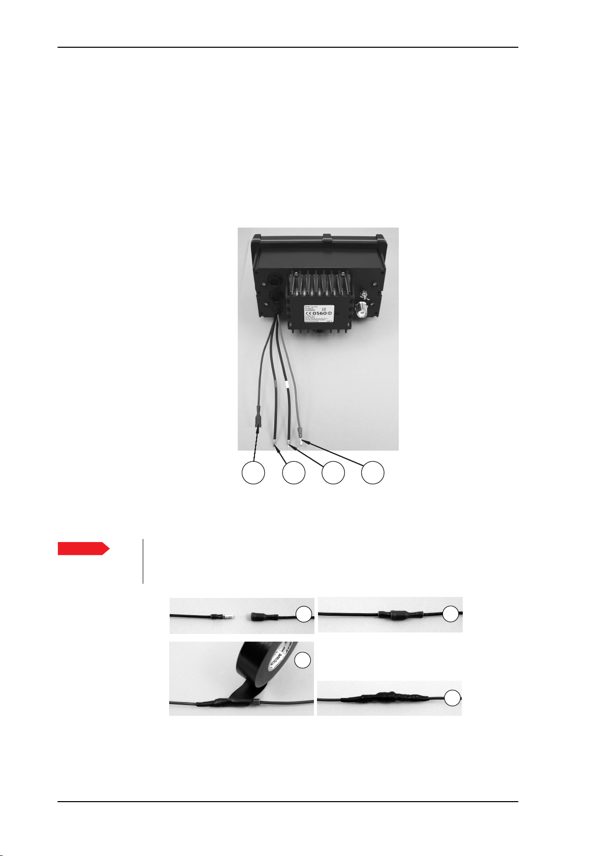
2.3.3 Power, Loudhailer, foghorn and external speaker
Use the connector marked PWR/EXT to connect power, loudhailer and an external speaker.
The cable for this connector is part of the delivery.
1. Blue wire: Power -
2. Red isolation on inner connector: loudhailer
3. White isolation on inner connector: external speaker
4. Red wire: Power +
Figure 2-13: Power, loudhailer, foghorn and external speaker
Protection against water ingress
Important
You must protect the cable connection with rubber vulcanizing tape as shown in the
pictures below. This protection prevents water seeping into the VHF radio, cable and
connectors.
1
Figure 2-14: Protection against water ingress
2
3 4
1
3
2
4
2-20 Chapter 2: Installation

SAILOR 6210 VHF Power, VHF antenna and external equipment
2.3.4 VHF antenna
Use the connector marked ANT to connect the VHF antenna to the radio with a 50 Ohm
coaxial cable with low loss, e.g. RG214. Install a PL259 plug at the cable end.
Place the antenna as high and clear of obstructions as possible. Make sure that the
horizontal distance to metal parts is minimum 1.5 m (5 ft).
Connector type: female SO239 for PL259 plug.
2.3.5 Ground stud
To ground the radio connect a ground wire from the ground stud of the radio to a suitable
grounding point. Use an appropriately sized wire. The ground stud is located above the VHF
antenna connector.
2222
Installation
Figure 2-15: Ground stud
Chapter 2: Installation 2-21

VHF antenna installation SAILOR 6210 VHF
2.4 VHF antenna installation
The SAILOR 6210 VHF is be installed with only one antenna for VHF RX/TX and DSC. You
can install all commonly available 50 Ohm antennas covering the appropriate frequency
range and providing a VSWR less than 1.5 over this range.
For further details on equipment and antenna installation, see IMOCOMSAR/Circ. 32,
GUIDELINES FOR THE HARMONIZATION OF GMDSS REQUIREMENTS FOR RADIO
INSTALLATIONS ON BOARD SOLAS SHIPS.
2.4.1 Cable requirements
Connect the antennas using a low loss type 50 Ohm coaxial cable, e.g. good quality RG214
or better. IMO-COMSAR/Circ. 32 recommends the use of a double screened type cable (like
e.g. RG214) with a maximum insertion loss of 3dB across the antenna cable installation.
The maximum antenna cable length in the installation depends on the quality of the cable,
i.e. the specified attenuation (dB/m) of the cable of choice at the high end of the VHF
frequency band. As a rule of thumb the cable length using e.g. RG214 coaxial cable should
not exceed 25 m.
2.4.2 VHF RX/TX antenna
In installations with two or more VHF radios it is important to ensure the optimum
performance of these by carefully selecting the antenna positions for both radios. It is
recommended to maximize the RF attenuation between the VHF RX/TX antennas in the
installation. You can ensure this by not having the RX/TX antennas positioned at the same
horizontal level, i.e. the RX/TX antennas for each radio must be installed at shifted
elevations as shown in the following drawing.
If sufficient vertical distance between two or more such antennas cannot be achieved, the
horizontal distance between them is increasingly important for optimum performance. If
there is hardly any vertical separation ensure that there is a minimum of 5 m horizontal
distance between any RX/TX antennas in the installation.
To minimize any increase in VSWR of the VHF RX/TX antenna, install the antenna at a
vertical distance of at least 2 m to any other mast, pole or other RF antennas. Keep VHF
antennas as far away as possible from antenna main beam of any radar and satellite
equipment.
2-22 Chapter 2: Installation

SAILOR 6210 VHF VHF antenna installation
RX/TX
DSC
RX/TX
DSC
No. 1 VHF No. 2 VHF
No. 2 VHF No. 1 VHF
39679
RX/TX
DSC
RX/TX
DSC
No. 1 VHF No. 2 VHF
No. 2 VHF No. 1 VHF
39679
2222
Installation
Figure 2-16: Antenna positioning
Figure 2-17: Antenna positioning 1/2
Chapter 2: Installation 2-23

System setup SAILOR 6210 VHF
This Handset has a hook-on/off function,
which is activated by a small magnet embedded
in the cradle.
The cradle must be installed as illustrated in
order to ensure the hook-on/off functionality
of the Handset.
75
62
226
* 120
min. 100
Space for handset access
Space for cable and handset cable
54
45
135
39655C
Drilling plan
2.5 System setup
To change a setting in the SYSTEM SETUP, do as follows:
1. Press the soft key SETUP. If it is not in the display, press the soft key MORE until
SETUP appears.
2. Press the arrow soft key or to advance to SYSTEM SETUP.
3. Turn the selector wheel knob to go to a setting, then press the selector
wheel knob to change the setting.
4. Press EXIT to return to normal radio operation
.
SYSTEM SETUP Description
Inactivity timeout Inactivity time-out to exit functions (e.g. in setup) and
return to the application.
Range: 1 to 30 minutes, in 1 minute steps
Default: 10 min.
Factory Defaults Resets the radio to factory defaults.
SW version Software version of the radio
S/N Serial number of the radio
Table 2-5: System setup
2.6 SAILOR 6201 Handset cradle (optional)
2-24 Chapter 2: Installation
Figure 2-18: Handset.

SAILOR 6210 VHF Accessories
2.7 Accessories
2.7.1 Part numbers for accessories
The following accessories are available for the SAILOR 6210 VHF:
Part number Accessories available
406201A SAILOR 6201 Handset with cradle (additional)
2222
406202A SAILOR 6202 Hand Microphone
406203A SAILOR 6203 Handset Waterproof
406204A SAILOR 6204 Control Speaker Microphone
406207A SAILOR 6207 Connection Box with Cable 406209-941
406208A SAILOR 6208 Connection Box with Cable 406208-941
406209-940 Connection Cable for bulkhead mount, 5 m, 1-x10 pole
406209-941 Connection Cable, 5 m, 1x10 pole
406204-940 Cable for SAILOR 6204 Control Speaker Microphone
406270A SAILOR 6270 External loudspeaker
406090A SAILOR 6090 Power Converter 24 V — 12 V
Table 2-6: Part numbers for accessories
Installation
Chapter 2: Installation 2-25

Accessories SAILOR 6210 VHF
12
11
10
9
8
7
6
5
4
3
2
1
12
11
10
9
8
7
6
5
4
3
2
1
12
11
10
9
8
7
6
5
4
3
2
1
VHF 62XX
Handset 2
Handset 1
99-132868-A
J1
J2
J3
Wire color
Pin
Brown
1
Blue
2
White
3
Green
4
Yellow
5
Grey
6
Pink
7
Red
8
Black
9
10
Orange
NMEA in+
NMEA in-
NMEA HS in-
NMEA HS in+
Mike 2 / Line in
Ear 2 / Line out
Hook_PTT
Bat_SW Supply voltage when on
Internal GND = - Battery
Internal GND = - Battery
Description
11
SCREEN (Drain)
Internal GND = - Battery
12
NC
2.7.2 Connection box SAILOR 6207
The SAILOR 6207 Connection Box is used to connect SAILOR 6201 Handsets. For
wiring and cabling details see System configuration examples on page B-1 .
Figure 2-19: SAILOR 6207 Connection Box for parallel handsets, mounting
Cable part no. 406209-941
To ensure galvanic separation of battery
supply from ship’s ground, the cable screens
of the ACC cables MUST not touch any part
of the metallic parts of the SAILOR 6207
Connection Box. Connect the screens only
to the pins at the terminals.
Figure 2-20: Connection Box for parallel handsets, wiring
2-26 Chapter 2: Installation

SAILOR 6210 VHF Accessories
2222
,E^dϭ
ϭϮϭ
ϱ
ϲ
ϳ
ϴ
ϵ
ϭϬ
ϭϭ
ϭϮ
ϮϯϲͲϰϭϮ:ϭϮϯϲͲϰϭϮ
,E^dϮ
ϭϮϭ
ϱ
ϲ
ϳ
ϴ
ϵ
ϭϬ
ϭϭ
ϭϮ
ϮϯϲͲϰϭϮ:ϮϮϯϲͲϰϭϮ
ϭϮs
:ϭ
Ϯ
ϯϯ
ϰϰ
ϱ
D/ϭ
ϲ
Z
ϳ
,KK<Wddϭ
ϴ
sd
ϵ
ϭϬ
ϭϭ
ϭϮ
-VBAT
:Ϯ
Ϯ
ϯϯ
ϰϰ
ϱ
D/Ϯ
ϲ
Z
ϳ
,KK<WddϮ
ϴ
sd
ϵ
ϭϬ
ϭϭ
ϭϮ
-VBAT
>ϭ
ϲϬϬZϭϬϬD,nj>ϭϲϬϬZϭϬϬD,nj
>ϯ
ϲϬϬZϭϬϬD,nj>ϯϲϬϬZϭϬϬD,nj
>ϱ
ϲϬϬZϭϬϬD,nj>ϱϲϬϬZϭϬϬD,nj
>ϳ
ϲϬϬZϭϬϬD,nj>ϳϲϬϬZϭϬϬD,nj
ϴs
ϭ
ϮϳϬƉ&ϭϮϳϬƉ&
-VBAT
ϰ
ϮϳϬƉ&ϰϮϳϬƉ&
-VBAT
ϲ
ϮϳϬƉ&ϲϮϳϬƉ&
-VBAT
ϴ
ϮϳϬƉ&ϴϮϳϬƉ&
-VBAT
ϴs ϴs
Zϭϴ
Zϭϴ
Ϯ
ϭϱϰŬ
ϭϱϰŬ
ZϮ
ϭ
Yϭ
ϭϮ
Zϭ
Zϭ
ϴϵϭ
ϴϵϭ
ϴϬϳͲϰϬtYϭϴϬϳͲϰϬt
ϭϬϬŬZϮϭϬϬŬ
ϯ
Zϯ
ϭϱϰŬZϯϭϱϰŬ
-VBAT
,KK<ϭ
,KK<Ϯ
ϴs ϴs
ZϮϭ
ZϮϭ
Ϯ
ϭϱϰŬ
ϭϱϰŬ
Zϭϰ
Zϭϰ
ϭ
Yϳ
ϭϮ
ZϮ
ZϮ
ϴϵϭ
ϴϵϭ
ϴϬϳͲϰϬtYϳϴϬϳͲϰϬt
ϭϬϬŬ
ϭϬϬŬ
ϯ
Zϭϱ
Zϭϱ
ϭϱϰŬ
ϭϱϰŬ
-VBAT
Ϯ
ϭϬϬŶ&ϮϭϬϬŶ&
-VBAT
hϭ
hϭ
ϭϰ
ϭϯ
s
ϭ
Ϯ
zϭϭϭ
ϳ
'E
ϳϰ,dϰϬϲϲ
ϳϰ,dϰϬϲϲ
-VBAT
hϭ
hϭ
ϱ
Ϯ
ϯ
zϮϰϮ
ϳϰ,dϰϬϲϲ
ϳϰ,dϰϬϲϲ
Zϳ
ϭϬϬŬZϳϭϬϬŬ
ZϭϬ
ZϭϬ
ϭϬϬŬ
ϭϬϬŬ
WWdϭ
WWdϮ
hϭ
hϭ
ϲ
ϯ
ϵ
zϯϴϯ
ϳϰ,dϰϬϲϲ
ϳϰ,dϰϬϲϲ
hϭ
hϭ
ϭϮ
ϰ
ϭϬ
zϰϭϭϰ
ϳϰ,dϰϬϲϲ
ϳϰ,dϰϬϲϲ
ϭϭs
Ϯ
Zϰ
ϭϬϬŬZϰϭϬϬŬ
ϭ
YϮ
ϴϬϳͲϰϬtYϮϴϬϳͲϰϬt
Zϱ
ϭϱϰŬZϱϭϱϰŬ
Zϲ
ϮϮϲŬZϲϮϮϲŬ
Zϵ
ϮϮϲŬZϵϮϮϲŬ
ϴs
Zϭϵ
Zϭϵ
ϱϲϮZ
ϱϲϮZ
ϯ
ϯ
ϭ
Yϯ
ϴϭϳͲϰϬtYϯϴϭϳͲϰϬt
Zϴ
Ϯ
ϮϳϰŬZϴϮϳϰŬ
ϯ
ϭ
Yϰ
ϴϭϳͲϰϬtYϰϴϭϳͲϰϬt
Ϯ
ZϮϮϭŬZϮϮ
ϭŬ
ϯ
-VBAT
ZϭϭϭŬZϭϭ
ϭ
Yϱ
ϴϭϳͲϰϬtYϱϴϭϳͲϰϬt
ϭŬ
Ϯ
ϯ
-VBAT
ZϭϮϭŬZϭϮ
ϭ
Yϲ
ϴϭϳͲϰϬtYϲϴϭϳͲϰϬt
ϭŬ
Ϯ
-VBAT
>Ϯ
ϲϬϬZϭϬϬD,nj>ϮϲϬϬZϭϬϬD,nj
ϯ
ϮϳϬƉ&ϯϮϳϬƉ&
-VBAT
s,&ϲϮyy
:ϯ
ϭϮϭ
Ϯ
ϯϯ
ϰϰ
ϱ
ϱ
>ϰ
ϲϬϬZϭϬϬD,nj>ϰϲϬϬZϭϬϬD,nj
ϱ
ϮϳϬƉ&ϱϮϳϬƉ&
-VBAT
>ϲ
ϲϬϬZϭϬϬD,nj>ϲϲϬϬZϭϬϬD,nj
ϳ
ϮϳϬƉ&ϳϮϳϬƉ&
D/ϭнϮ
Z
,KK<WddϭнϮ
sd
ϲ
ϲ
ϳ
ϳ
ϴ
ϴ
ϵ
ϵ
ϭϬ
ϭϬ
ϭϭ
ϭϭ
ϭϮ
ϭϮ
ϮϯϲͲϰϭϮ:ϯϮϯϲͲϰϭϮ
-VBAT
Installation
-VBAT
Figure 2-21: SAILOR 6207 Connection Box for parallel handsets, diagram
Chapter 2: Installation 2-27

Accessories SAILOR 6210 VHF
12
11
10
9
8
7
6
5
4
3
2
1
12
11
10
9
8
7
6
5
4
3
2
1
12
11
10
9
8
7
6
5
4
3
2
1
CAN bus termination
99-132881-A
J1
J2
J3
R1
W1
2.7.3 Connection box SAILOR 6208
The SAILOR 6208 Connection Box is used to connect SAILOR 6204 Control Speaker
microphones and other auxiliary equipment. For wiring and cabling details see System
configuration examples on page B-1.
Figure 2-22: SAILOR 6208 Control Unit Connection Box, mounting
Jumper for CAN bus termination.
Secure cables with cable strips.
Figure 2-23: SAILOR 6208 Control Unit Connection Box for parallel handsets, wiring
2-28 Chapter 2: Installation

SAILOR 6210 VHF Accessories
Terminate the last SAILOR 6208 on the CAN bus (furthest away from the transceiver).
Figure 2-24: SAILOR 6208 Control Unit Connection Box, diagram
2222
Installation
Chapter 2: Installation 2-29

Accessories SAILOR 6210 VHF
2-30 Chapter 2: Installation

Chapter 3
First-time power up 3
3.1 General use and navigation
3.1.1 Power on and speaker volume
The VHF radio has a dual-function on/off wheel knob for power on/off and
volume control.
• To power on the VHF radio press the on/off wheel knob.
• To power off the VHF radio, press and hold the on/off wheel knob and
follow the instructions in the display.
3333
• To adjust the speaker volume, turn the volume wheel knob (clockwise = louder, counter
clockwise = softer, until muted). When adjusted to the muted level is shown in the
display.
3.1.2 Working channel, settings and dim function
The selector wheel knob has several functions:
• To select the working channel, turn the selector wheel knob.
• To browse and select settings, turn the selector wheel knob and press for
accept.
•To dim the backlight in the display until it is appropriate for the current situation, i.e.
to give comfortable night vision, press, hold and turn the selector wheel knob
(clockwise= more light).
First-time power up
3-31

General use and navigation SAILOR 6210 VHF
3-32 Chapter 3: First-time power up

Chapter 4
Service & maintenance 4
4.1 Contact for support
Contact your authorized dealer for technical service and support of the VHF radio. Before
contacting your authorized dealer you can go through the troubleshooting guide to solve
some of the most common operational problems.
4.2 Maintenance
4.2.1 Preventive maintenance
4444
Maintenance of the SAILOR 6210 VHF can be reduced to a maintenance check at each visit
of the service staff. Inspect the radio for mechanical damages, salt deposits, corrosion and
any foreign material. Due to its robust construction and ruggedness the radio has a long
lifetime. Anyway it must carefully be checked at intervals not longer than 12 months dependent on the current working conditions.
Salt deposits
In case the equipment has been exposed to sea water there is a risk of salt crystallization on
the keys and wheel knobs and they may become inoperable. Clean the VHF radio and
speaker microphones with fresh water.
4.2.2 Error messages and warnings
Errors and warning messages are shown in the display and are read-only.
4.2.3 Troubleshooting guide
Action Symptom Remedy
The radio will
not turn on
The display is
empty.
Check if power is present.
Check fuse which is placed in the + supply wire.
Service & maintenance
No communication
Handset
configuration
The loudspeaker
is mute.
No sound in
earpiece
Table 4-1: Troubleshooting guide
Check performance of power supply if connected to
one.
Check the antenna installation.
Check antenna cable.
Check handset/Handmicrophone and cable.
The earpiece volume may be configured to OFF. See
section Controller setup on page 2-10 on how to
adjust the earpiece volume of the handset.
4-33

Maintenance SAILOR 6210 VHF
Action Symptom Remedy
Device failure If any of the checks and tests described in this
section do not assist in resolving the difficulties
experienced in the operation and/or performance of
the VHF installation, a fault may have developed in
the VHF radio itself.
When contacting an authorized Thrane & Thrane
representative be sure to provide as much
information as possible describing the observed
behavior - also including the type of the VHF radio,
its serial number, and software release version (both
found in the setup menu Controller Setup).
Table 4-1: Troubleshooting guide (Continued)
4-34 Chapter 4: Service & maintenance

SAILOR 6210 VHF Maintenance
4.2.4 Replacing the fuse in the red wire (Power +)
One fuse is installed in the supplied DC cable. If the fuse
is blown, track down why the fuse was blown and solve
the problem. To replace the fuse, do as follows:
1
1. Hold both ends of the fuse holder and pull it apart.
2. Take out the old fuse.
4444
3. Insert the new fuse. The fuse rating is 10 A T.
4. Make sure that the fuse is tightly fixed on the metal
contact inside the fuse holder.
5. Put together the fuse holder.
2
3
4.2.5 Replacing the fuse in the SAILOR 6090 Power Converter
One fuse is installed in the SAILOR 6090 Power Converter. If the fuse is blown, do as
follows:
1. Track down why the fuse was blown and solve the problem.
2. Take out the old fuse.
3. Insert the new fuse. The fuse rating is 10 A T.
Service & maintenance
Figure 4-1: Fuse in the SAILOR 6090 Power Converter
Chapter 4: Service & maintenance 4-35

Returning units for repair SAILOR 6210 VHF
4.3 Returning units for repair
Should your Cobham SATCOM product fail, please contact your dealer or installer, or the
nearest Cobham SATCOM partner. You will find the partner details on
www.cobham.com/satcom where you also find the Cobham SATCOM Self Service Center
web-portal, which may help you solve the problem.
Your dealer, installer or Cobham SATCOM partner will assist you whether the need is user
training, technical support, arranging on-site repair or sending the product for repair.
Your dealer, installer or Cobham SATCOM partner will also take care of any warranty issue.
4.3.1 Repacking for shipment
Should you need to send the product for repair, please read the below information before
packing the product.
The shipping carton has been carefully designed to protect the SAILOR 6210 VHF and its
accessories during shipment. This carton and its associated packing material should be used
when repacking for shipment. Attach a tag indicating the type of service required, return
address, part number and full serial number. Mark the carton FRAGILE to ensure careful
handling.
Note
If the original shipping carton is not available, the following general instructions should be
used for repacking with commercially available material.
1. Wrap the defective unit in heavy paper or plastic. Attach a tag indicating the type of
2. Use a strong shipping container, e.g. a double walled carton.
3. Protect the front- and rear panel with cardboard and insert a layer of shock-absorbing
4. Seal the shipping container securely.
5. Mark the shipping container FRAGILE to ensure careful handling.
Failure to do so may invalidate the warranty.
Correct shipment is the customer’s own responsibility.
service required, return address, part number and full serial number.
material between all surfaces of the equipment and the sides of the container.
4-36 Chapter 4: Service & maintenance

Appendix A
Technical specifications A
A.1 SAILOR 6210 VHF
Item Specification
Weight SAILOR 6210 VHF approx. 1.2 kg, 2.65 lbs
AAAA
Technical specifications
Weight SAILOR 6210 VHF and
Handmicrophone
Dimensions
Operating temperature -15°C to 55°C
Storage temperature -30°C to 80°C
Power supply 12 VDC Nominal (10,8– 15,6 VDC)
Current consumption Max. 7 A
Frequency range TX 156,000-161,450,
Channel spacing 12,5 kHz and 25 kHz, all international maritime channels
Number of P channels The radio may be programmed with up to 40 private channels
approx. 1,5 kg 3,31 lbs including SAILOR 6202 Handmicrophone
and mounting bracket
Height: Outer dimension 106 mm, hole height for flush mount 89
mm
Width: Outer dimension 190 mm, hole width for flush mount 177
mm
Depth: Outer dimension from front of wheel knobs 132 mm,
depth for flush mount 94 mm
RX 156,000-163.425 MHz
that can be managed in all channel modes.
Transmit power Hi/Lo: 25 W and <1 W
RF output power 25 W +0 dB / - 1.5 dB
1 W +0 dB / - 1.5 dB
RF output power, Canada 21 W ±0.75 dB / 0.8 W ±0.75 dB
Modulation
25 kHz
12.5 kHz
16K0G3E
8K05G3E
Table A-1: Technical specifications
A-37

SAILOR 6210 VHF SAILOR 6210 VHF
Item Specification
LF power Built-in loudspeaker: 6 W
External loudspeaker: 6 W / 8 Ohm
Loudhailer: 30 W / 4 Ohm (when the unit is not transmitting)
Receiver sensitivity < -119 dBm typically @ 20 dB SINAD CCITT weighted
Antenna 50 Ohm antenna, 50 Ohm female SO239 for PL259 plug
Water ingress IPx8 and IPx6 all over. For flush-mount installations a sealing
gasket is included in the delivery.
Table A-1: Technical specifications (Continued)
A-38 Chapter A: Technical specifications

Appendix B
System configurations B
This appendix lists selected examples of system configurations.
For an overview and specifications of the cables needed see
BBBB
Note
For installation of the connection boxes see Connection box SAILOR 6207 on
page 2-26 and Connection box SAILOR 6208 on page 2-28
B.1 System configuration examples
The following list shows system configurations, with handset, connection boxes and cable
information
1. How to install a SAILOR 6204 CSM far from the VHF radio
2. How to install a SAILOR 6204 close to the VHF radio
3. How to install a SAILOR 6204 very close to the VHF radio
System configurations
B-39
System configuration examples SAILOR 6210 VHF
B.1.1 How to install a SAILOR 6204 CSM far from the VHF radio
SAILOR 6204
Control
RX/TX
Speaker Microphone
(Without DSC)
2
SAILOR 6201/03
SAILOR N163S
Power Supply
110VAC/230VAC
1
SAILOR 6208
Connection box
SAILOR 6210
VHF
2
12VDC
3
Brown/Drain
24VDC
Blue
White
Green
Yellow
Grey
Pink
Red
Black
Orange
Violet
Cyan
CTRL
5m
8
16
<100m
Remove jumper
Shield/GND
-battery
+battery
+battery
CAN_H
CAN_L
-battery
On/off from CSM
RX+ telephony out
RX- telephony out
TX+ telephony in
TX- telephony in
Brown/Drain
Blue
White
Green
Yellow
Grey
Pink
Red
Black
Orange
Violet
Cyan
24VDC
Figure B-1: How to install a SAILOR 6204 CSM far from the VHF
SAILOR 6208
Connection box
Place jumper for
5m
17
termination
Shield/GND
-battery
+battery
+battery
CAN_H
CAN_L
-battery
On/off from CSM
RX+ telephony out
RX- telephony out
TX+ telephony in
TX- telephony in
15
B-40 Chapter B: System configurations

SAILOR 6210 VHF System configuration examples
B.1.2 How to install a SAILOR 6204 close to the VHF radio
SAILOR 6204
Control
RX/TX
Speaker Microphone
(Without DSC)
BBBB
SAILOR 6202
2
1
SAILOR 6201/03
SAILOR 6210
VHF
SAILOR N163S
Power Supply
110VAC/230VAC
2
12VDC
3
Brown/Drain
24VDC
24VDC
Blue
White
Green
Yellow
Grey
Pink
Red
Black
Orange
Violet
Cyan
CTRL
5m
8
Remove jumper
Figure B-2: How to install a SAILOR 6204 close to the VHF radio
SAILOR 6208
Connection box
Shield/GND
-battery
+battery
+battery
CAN_H
CAN_L
-battery
On/off from CSM
RX+ telephony out
RX- telephony out
TX+ telephony in
TX- telephony in
15
System configurations
17
5m
Chapter B: System configurations B-41

System configuration examples SAILOR 6210 VHF
B.1.3 How to install a SAILOR 6204 very close to the VHF radio
SAILOR 6204
Control
Speaker Microphone
(Without DSC)
5m
Place jumper so power supply
always is switched on
15
NC
NC
-Vout (Black)
+Vout (Red)
SAILOR 6202
2
SAILOR 6201/03
RX/TX
1
2
SAILOR 6210
VHF
12VDC
3
CTRL
10
10
24VDC
SAILOR N163S
Power Supply
110VAC/230VAC
24VDC
Figure B-3: How to install a SAILOR 6204 very close to the VHF radio
Ground
10
Screen/ground
-Vin
+Vin
B-42 Chapter B: System configurations

SAILOR 6210 VHF Cable requirements
B.2 Cable requirements
The following cable information relates to the cable numbers in the system configuration
drawings on the previous pages.
Cable Part number Description Specification Remarks
1 Antenna cable RG214 or better
2 Handset cable 1 m, spiraled Part of handset
3 Power cable 1.5 m power cable Included in 406210A
BBBB
8 406208-941
10 0.3 m Earth connection
15 Cable for SAILOR 6204
16 Cable for CAN Screened with twisted
17 406204-940 As cable (12). Plug for
Cable 1
Cable type: Coax cable RG 214 or better.
5 m cable for SAILOR 6208
Connection box
Control Speaker
Microphone
CTRL is removed and
wires connected to
connection box
Table B-1: Cable overview
12-pole LTW cable
with screen
2.5 m, spiraled Part of handset
pairs, length and size
see cable description
for Cable 16 on
page B-45.
12-pole LTW cable
with screen
Included in Connection
box 406208A
Extension cable for
CAN bus, see also under
cable description for
Cable 16 on page B-45.
Extension cable with
LTW bulk mount plug
System configurations
Chapter B: System configurations B-43

Cable requirements SAILOR 6210 VHF
Cable 2 (Handset, cable included)
SAILOR 6210 VHF Front
connector
LTW 10-pin, circular male
Signal
designation
Signal description
Pin 1 NC
Pin 2 NC
Pin 3 NC
Pin 4 NC
Pin 5 MIC+ Microphone signal
Pin 6 Earpiece Earpiece signal
Pin 7 Hook_PTT Hook/PTT signal
Pin 8 Battery+ (10.8-15.6 VDC) Battery supply when radio is on
Pin 9 Internal GND = -Battery Equipment ground
Pin 10 Internal GND = -Battery Equipment ground
Table B-2: Cable specifications for cable 2
CAN cable (Cable 8 - CTRL)
Part number: 406208-941
SAILOR 6210
VHF
CTRL
connector
LTW 12-pin,
circular male
Pin 1 Shield/GND Brown J1-1 J2-1 J3-1 Equipment ground paired with no. 8
Pin 2 Battery- Blue J1-2 J2-2 J3-2 Battery - paired with no. 3
Pin 3 Battery+ White J1-3 J2-3 J3-3
Pin 4 Battery+ Green J1-4 J2-4 J3-4
Pin 5 CAN_H Yellow J1-5 J2-5 J3-5 CAN bus data paired with no. 6
Pin 6 CAN_L Grey J1-6 J2-6 J3-6 paired with no. 5
Pin 7 Battery- Pink J1-7 J2-7 J3-7 Battery - paired with no. 4
Pin 8 ON/OFF
Signal
designation
from CSM
Cable
pin
406208-
941
(5 m)
Red J1-8 J2-8 J3-8 ON/OFF signal from Control
SAILOR
6208
Conn. Box
In from
VHF
SAILOR
6208
Conn. Box
Out of box
SAILOR
6208
Conn. Box
Out of box
Signal description
10.8-15.6 VDC from VHF radio
10.8-15.6 VDC from VHF radio
Speaker Microphone
Ships cable
6 twisted pairs
overall screen
paired with no. 2
paired with no. 7
paired with no. 1
Table B-3: Cable specifications for cable 8 (CTRL)
B-44 Chapter B: System configurations

SAILOR 6210 VHF Cable requirements
BBBB
SAILOR 6210
VHF
CTRL
connector
LTW 12-pin,
circular male
Pin 9 RX+ Black J1-9 J2-9 J3-9 RX telephony (out) paired with no. 10
Pin 10 RX- Orange J1-10 J2-10 J3-10 paired with no. 9
Pin 11 TX+ Purple J1-11 J2-11 J3-11 TX telephony (in) paired with no. 12
Pin 12 TX- Light
Signal
designation
Cable
pin
406208-
941
(5 m)
green
SAILOR
6208
Conn. Box
In from
VHF
J1-12 J2-12 J3-12 paired with no. 11
Table B-3: Cable specifications for cable 8 (CTRL)
SAILOR
6208
Conn. Box
Out of box
SAILOR
6208
Conn. Box
Out of box
Signal description
Ships cable
6 twisted pairs
overall screen
Cable 16
The CAN bus cable must be of a paired and twisted type designed for the purpose. The CAN
bus cable can handle signals up to 100 m away from the VHF to further Control Speaker
Microphones (CSM).
Only 1 CSM can be connected to the VHF with a CAN bus cable of max 100 m if the cable
dimension is 0.5mm² of each cord. Other combinations with more CSMs must be calculated
seriously before installing the cable. If more CSMs are connected, the CAN cable of 0.5mm²
can handle the signals up to max. 100 m. The only restriction is the power supply for the
connected CSMs.
System configurations
The voltage drop along the cable increases with the length of the cable. Separate supply
cables can be installed in parallel with the CAN cable to reduce voltage drop in long cables.
The maximum allowed voltage drop from VHF to CSM is 2 VDC. It means 1 VDC forward
and 1 VDC return.
Max current consumption for each CSM is 0.5A.
Formula to calculate DC resistance in a wire:
R 0 017 L a=
L = length of wire one way, in metre
a = cross section of the wire in mm²
Contact your local dealer for further information for correct installation.
Cable 17 CAN cable for bulk head installation.
Same cable as cable 12, but the plug is removed and the wires are connected to the
connection box.
Same pin configuration as cable 8. See
44
.
Cable specifications for cable 8 (CTRL) on page B-
Contact your local dealer for further information for correct installation.
Chapter B: System configurations B-45

Cable requirements SAILOR 6210 VHF
B-46 Chapter B: System configurations

Glossary
Glossary 3
A
ACC Accessories
C
CAN Controller-Area Network. A message based protocol designed to allow microcontrollers
and devices to communicate with each other within a vehicle without a host computer.
CTRL Control
3333
E
EXT External
G
GGA NMEA sentence, essential fix data which provide 3D location and accuracy data.
GLL NMEA sentence, Geographic Latitude and Longitude
GNS NMEA sentence,
N
NMEA National Marine Electronics Association, specification for communication between
marine electronic devices
P
PWR Power
Glossary
R
RMC NMEA sentence, version of essential gps position, velocity, time data.
V
VDR Voyage Data Recorder, a data recording system designed for all vessels required to
comply with the IMO’s International Convention SOLAS Requirements in order to collect
data from various sensors on board the vessel.
VHF Very High Frequency
Glossary-47

Glossary SAILOR 6210 VHF
Z
ZDA NMEA sentence, date and time.
Glossary-48

Index
Index 4
4444
A
ACC connector, 2-16
adjusting
speaker volume
ANT connector, 2-21
, 3-31
B
backlight, 1-1
dim, 3-31
browse channels, 3-31
C
cable
CAN
, B-44
cable for VHF antenna, 2-21
cable overview, B-43
CAN cable, B-44
channel
select
, 3-31
working, 3-31
compass safe distance, 2-8
configuration
system example
connector
ACC
, 2-16
ANT, 2-21
CTRL, 2-19
external speaker, 2-20
foghorn, 2-20
loudhailer, 2-20
VHF antenna, 2-21
contact, 4-33
controls, front plate, 1-2
cradle for 6201, installation, 1-4, 2-24
CTRL connector, 2-19
, 1-6
document number, this manual, -i
DSC controller
external
, 2-16
E
error messages, 4-33
external speaker
cabling
connector, 2-20
, 2-20
F
factory defaults, 2-24
flush mount, 2-11
foghorn, 1-1
connector, 2-20
patterns, 1-1
frequency range, VHF, A-37
front plate, controls, 1-2
fuse
Power Converter
fuses, how to replace, 4-35
, 4-35
G
GPS input, 2-16, 2-26
H
hand microphone
installing
handset cradle
installation
how to replace, 4-35
, 2-14
, 1-4, 2-24
Index
D
default reset, 2-24
delivery, items included, 2-7
dim, 3-31
display, 1-2
I
input
GPS
, 2-26
handset, 2-26
Index-49

Index SAILOR 6210 VHF
installation
cradle for 6201
desktop, 2-9
flush mount, 2-11
handset cradle, 1-4, 2-24
mounting bracket, 2-10
overhead, 2-9
IP rating, A-38
, 1-4, 2-24
K
keys on front plate, 1-2
L
loud hailer
cabling
louder, volume, 3-31
loudhailer, 1-1
connector, 2-20
, 2-20
M
manual, document number, -i
mounting, 2-8
flush mount, 2-11
with mounting bracket, 2-10
R
replay, 1-1
button, 1-2
reset to default, 2-24
RF exposure hazards, -iii
S
safety summary, -iii
salt deposits, 4-33
selector wheel knob, 1-2, 3-31
semi duplex, 1-1
serial number, 2-24
service line, display, 1-2
setup
system
, 2-24
simplex, 1-1
softer, volume, 3-31
Software version, 2-24
speaker volume, 3-31
specifications, A-37
squelch control, 1-2
support, 4-33
SW version, 2-24
system configuration
example
system setup, 2-24
, 1-6
N
night vision, how to dim, 3-31
NMEA, 2-16
NMEA interface, 2-17
NMEA output, 2-17
P
power
cabling
fuse, 4-35
off, 3-31
on, 3-31
Power Converter
fuse
, 2-20
, 4-35
T
technical data, A-37
temperature
operational
storage, A-37
timeout, 2-24
, A-37
V
VHF
antenna cable
antenna connector, 2-21
frequency range, A-37
volume
louder
, 3-31
softer, 3-31
speaker, 3-31
Volume wheel knob, 1-2
, 2-21
Index-50

SAILOR 6210 VHF Index
W
warnings, 4-33
warranty, 4-36
limitation, -iii
water ingress, A-38
weight, A-37
wheel knob
selector
volume, 1-2
working channel, 3-31
, 1-2
4444
Index
Index-51

Index SAILOR 6210 VHF
Index-52

SAILOR 6215/6216 VHF DSC
Installation manual
Release date: November 14, 2013

SAILOR 6215/6216 VHF DSC
Disclaimer
Any responsibility or liability for loss or damage in connection with the use of this product and the
accompanying documentation is disclaimed by Thrane & Thrane A/S. The information in this manual is
provided for information purposes only, is subject to change without notice and may contain errors or
inaccuracies. Manuals issued by Thrane & Thrane A/S are periodically revised and updated. Anyone
relying on this information should acquire the most current version e.g. from www.cobham.com/satcom
or from the distributor. Thrane & Thrane A/S is not responsible for the content or accuracy of any
translations or reproductions, in whole or in part, of this manual from any other source.
Thrane & Thrane A/S is trading as Cobham SATCOM.
Copyright
© 2013 Thrane & Thrane A/S. All rights reserved. Printed in Denmark.
Trademark Acknowledgements
• SAILOR is a registered trademarks of Thrane & Thrane A/S.
• Other product and company names mentioned in this manual may be trademarks or trade names of
their respective owners.
ii

SAILOR 6215/6216 VHF DSC
Safety warning
The following general safety precautions must be observed during all phases of operation,
service and repair of this equipment. Failure to comply with these precautions or with specific
warnings elsewhere in this manual violates safety standards of design, manufacture and
intended use of the equipment. Thrane & Thrane assumes no liability for the customer's failure
to comply with these requirements.
RF exposure hazards and instructions
Your Thrane & Thrane radio set generates electromagnetic RF (radio frequency) energy when
transmitting. To ensure that you and those around you are not exposed to excessive amounts
of energy and thus to avoid health hazards from excessive exposure to RF energy, all persons
must be at least 3ft (0.9 m) away from the antenna when the radio is transmitting.
Warranty limitation
IMPORTANT - The radio is a sealed waterproof unit (classified IPX8). To create and maintain its
waterproof integrity it was assembled in a controlled environment using special equipment. The
radio is not a user maintainable unit, and under no circumstances should the unit be opened
except by authorized personnel. Unauthorized opening of the unit will invalidate the warranty.
Installation and service
Installation and general service must be done by skilled service personnel.
iii

SAILOR 6215/6216 VHF DSC
Manual overview
This manual has the following chapters:
• Introduction contains a description of the VHF radio.
• Installation explains how to mount the VHF radio and how to connect accessories and external
equipment.
• First-time power up explains how to make and receive voice and DSC calls over VHF, including how to
use and set-up the channel scanning, the 2-way loudhailer, fog horn external loudspeaker.
• Service & maintenance contains support information including lists of accessories and a
troubleshooting guide.
Appendices with Technical specifications and System configurations.
iv

SAILOR 6215/6216 VHF DSC
SAILOR 6216 only
Preface
Radio for occupational use
The SAILOR 6216 VHF DSC fulfils the requirements of the EC directive 1999/5/EC, Radio and
Telecommunications Terminal Equipment and is intended for use in maritime environment.
SAILOR 6216 VHF DSC is designed for occupational use only and must be operated by licensed
personnel only.
SAILOR 6216 VHF DSC is not intended for use in an uncontrolled environment by general public.
SAILOR 6216 VHF DSC is designed for installation by a skilled service person.
Training information
The SAILOR 6216 VHF DSC is designed for "occupational use only" and is also classified as such. It must
be operated by licensed personnel only. It must only be used in the course of employment by individuals
aware of both the hazards as well as the way to minimize those hazards
The radio is thus NOT intended for use in an uncontrolled environment by general public. The SAILOR
6216 VHF DSC has been tested and complies with the FCC RF exposure limits for "Occupational Use
Only". The radio also complies with the following guidelines and standards regarding RF energy and
electromagnetic energy levels including the recommended levels for human exposure:
• FCC OET Bulletin 65 Supplement C, evaluating compliance with FCC guidelines for human exposure to
radio frequency electromagnetic fields.
• American National Standards Institute (C95.1) IEEE standard for safety levels with respect to human
exposure to radio frequency electromagnetic fields, 3 kHz to 300 GHz
• American National Standards Institute (C95.3) IEEE recommended practice for the measurement of
potentially hazardous electromagnetic fields - RF and microwaves.
Below the RF exposure hazards and instructions in safe operation of the radio within the FCC RF exposure
limits established for it are described.
Warning
Your Thrane & Thrane radio set generates electromagnetic RF (radio frequency) energy when it is
transmitting. To ensure that you and those around you are not exposed to excessive amounts of that
energy (beyond FCC allowable limits for occupational use) and thus to avoid health hazards from
excessive exposure to RF energy, FCC OET bulletin 65 establishes an Maximum Permissible Exposure
(MPE) radius of 3 ft (0.9m) for the maximum power of your radio (25W selected) with an half wave omnidirectional antenna having a maximum gain of 3 dB (5.2dBi). This means all persons must be at least 3 ft
(0.9m) away from the antenna when the radio is transmitting.
v

SAILOR 6215/6216 VHF DSC
Installation
1. An omni-directional antenna with a maximum power gain of 5.2 dBi must be mounted at least 9.6 ft
(2.9m) above the highest deck where people may be staying during radio transmissions. The distance
is to be measured vertically from the lowest point of the antenna. This provides the minimum
separation distance which is in compliance with RF exposure requirements and is based on the MPE
radius of 3 ft (0,9m) plus the 6.6 ft (2m) height of an adult.
2. On vessels that cannot fulfil requirements in item 1, the antenna must be mounted so that its lowest
point is at least 3 ft (0.9m) vertically above the heads of people on deck and all persons must be
outside the 3 ft (0.9m) MPE radius during radio transmission.
• Always mount the antenna at least 3ft (0.9m) from possible human access.
• Never touch the antenna when transmitting
• Use only authorized T&T accessories.
3. If antenna has to be placed in public areas or near people with no awareness of the radio transmission,
the antenna must be placed at a distance not less than 6 ft (1.8m) from possible human access.
Failure to observe any of these warnings may cause you or other people to exceed FCC RF exposure
limits or create other dangerous conditions
vi

SAILOR 6215/6216 VHF DSC Table of Contents
Table of Contents
Chapter 1 Introduction
1.1 VHF radio with DSC ........................................................................................................1-1
1.2 Accessories available .....................................................................................................1-3
Chapter 2 Installation
2.1 Unpacking the SAILOR 6215/6216 VHF DSC ..............................................2-7
2.2 Installing the VHF radio ..............................................................................................2-8
2.3 Power, VHF antenna and external equipment ........................................2-15
2.4 VHF antenna installation .........................................................................................2-22
2.5 System setup ....................................................................................................................2-24
2.6 SAILOR 6201 Handset cradle (optional) ......................................................2-25
2.7 Accessories .........................................................................................................................2-26
Chapter 3 First-time power up
3.1 General use and navigation ...................................................................................3-31
3.2 Entering the MMSI number ...................................................................................3-32
Chapter 4 Service & maintenance
4.1 Contact for support .....................................................................................................4-33
4.2 Maintenance ......................................................................................................................4-33
4.3 Returning units for repair ........................................................................................4-38
Appendix A Technical specifications
A.1 SAILOR 6215/6216 VHF DSC ............................................................................... A-39
A.2 NMEA data rates and formats ............................................................................ A-40
Appendix B System configurations
B.1 System configuration examples ........................................................................B-41
B.2 Cable requirements ......................................................................................................B-45
Glossary ...........................................................................................................................................................Glossary-49
Index ................................................................................................................................................................ Index-51
vii

Table of Contents SAILOR 6215/6216 VHF DSC
viii

SAILOR 6215/6216 VHF DSC
List of figures
Figure 1-1: Controls on the front plate...........................................................................................................................1-2
Figure 1-2: System configuration - example................................................................................................................1-5
Figure 2-1: Desktop mounting ............................................................................................................................................2-9
Figure 2-2: Overhead mounting .........................................................................................................................................2-9
Figure 2-3: Mounting with U mounting bracket...................................................................................................... 2-10
Figure 2-4: Cutout for flush mount................................................................................................................................ 2-11
Figure 2-5: Flush mount details .......................................................................................................................................2-12
Figure 2-6: SAILOR 6090 Power Converter, dimensions.....................................................................................2-13
Figure 2-7: Connecting the SAILOR 6090 Power Converter .............................................................................2-13
Figure 2-8: Handmicrophone............................................................................................................................................ 2-14
Figure 2-9: Power, VHF antenna and external equipment..................................................................................2-15
Figure 2-10: NMEA interface description...................................................................................................................... 2-17
Figure 2-11: Power, loudhailer, foghorn and external speaker............................................................................2-20
Figure 2-12: Protection against water ingress.............................................................................................................2-20
Figure 2-13: Ground stud.......................................................................................................................................................2-21
Figure 2-14: Antenna positioning......................................................................................................................................2-23
Figure 2-15: Antenna positioning 1/2 .............................................................................................................................2-23
Figure 2-16: Handset. ..............................................................................................................................................................2-25
Figure 2-17: SAILOR 6207 Connection Box for parallel handsets, mounting.............................................. 2-27
Figure 2-18: Connection Box for parallel handsets, wiring ...................................................................................2-27
Figure 2-19: SAILOR 6207 Connection Box for parallel handsets, diagram .................................................2-28
Figure 2-20: SAILOR 6208 Control Unit Connection Box, mounting ..............................................................2-29
Figure 2-21: SAILOR 6208 Control Unit Connection Box for parallel handsets, wiring..........................2-29
Figure 2-22: SAILOR 6208 Control Unit Connection Box, diagram..................................................................2-30
Figure 4-1: Fuse in the SAILOR 6090 Power Converter.......................................................................................4-37
Figure B-1: How to install a SAILOR 6205 CSM far from the VHF radio......................................................B-42
Figure B-2: How to install a SAILOR 6205 close to the VHF radio..................................................................B-43
Figure B-3: How to install a SAILOR 6205 very close to the VHF radio .......................................................B-44
ix

SAILOR 6215/6216 VHF DSC
x

SAILOR 6215/6216 VHF DSC
List of tables
Table 1-1: Accessories available .......................................................................................................................................1-3
Table 2-1: Compass safe distance ...................................................................................................................................2-8
Table 2-2: ACC connector ................................................................................................................................................2-16
Table 2-3: NMEA interface............................................................................................................................................... 2-17
Table 2-4: CTRL connector for control speaker microphone ..........................................................................2-19
Table 2-5: System setup .................................................................................................................................................... 2-24
Table 2-6: Part numbers for accessories....................................................................................................................2-26
Table 4-1: Troubleshooting guide................................................................................................................................. 4-34
Table A-1: Technical specifications..............................................................................................................................A-39
Table A-2: NMEA data rates and formats..................................................................................................................A-40
Table B-1: Cable overview ................................................................................................................................................B-45
Table B-2: Cable specifications for cable 2...............................................................................................................B-46
Table B-3: Cable specifications for cable 8 (CTRL) ...............................................................................................B-46
xi

SAILOR 6215/6216 VHF DSC
xii

Chapter 1
Introduction 1
1111
1.1 VHF radio with DSC
SAILOR 6215/6216 VHF DSC, your new SAILOR
VHF radio with full DSC functionality, is
approved to R&TTE and is waterproof to the IPx8
and IPx6 standard. As part of the required safety
equipment, use the SAILOR 6215/6216 VHF DSC
in an emergency situation. However the best way
to guarantee functionality in an emergency
situation, is to use the radio in daily
communication on board.
The VHF radio is a simplex/semi duplex VHF
radio. It is designed with an easy-to-use menu-driven setup. You use the soft-keys to enter
the desired functions, you browse and select a setting using the right selection wheel knob.
The large display has red adjustable backlight which provides a good visibility even at night
and protects your night vision.
The VHF radio can replay the last 90 s of received voice. This is a useful feature to minimize
misunderstandings and to record messages when the radio is unattended.
The VHF radio connects easily to external equipment like a 2-way loudhailer and an
external speaker. You can use the loudhailer as a 2-way on-board communicator. The
loudhailer also functions as a fog horn. You can select from several programmed fog-horn
patterns.
Introduction
For a list of other accessories available for the SAILOR 6215/6216 VHF DSC check with your
nearest distributor.
1-1
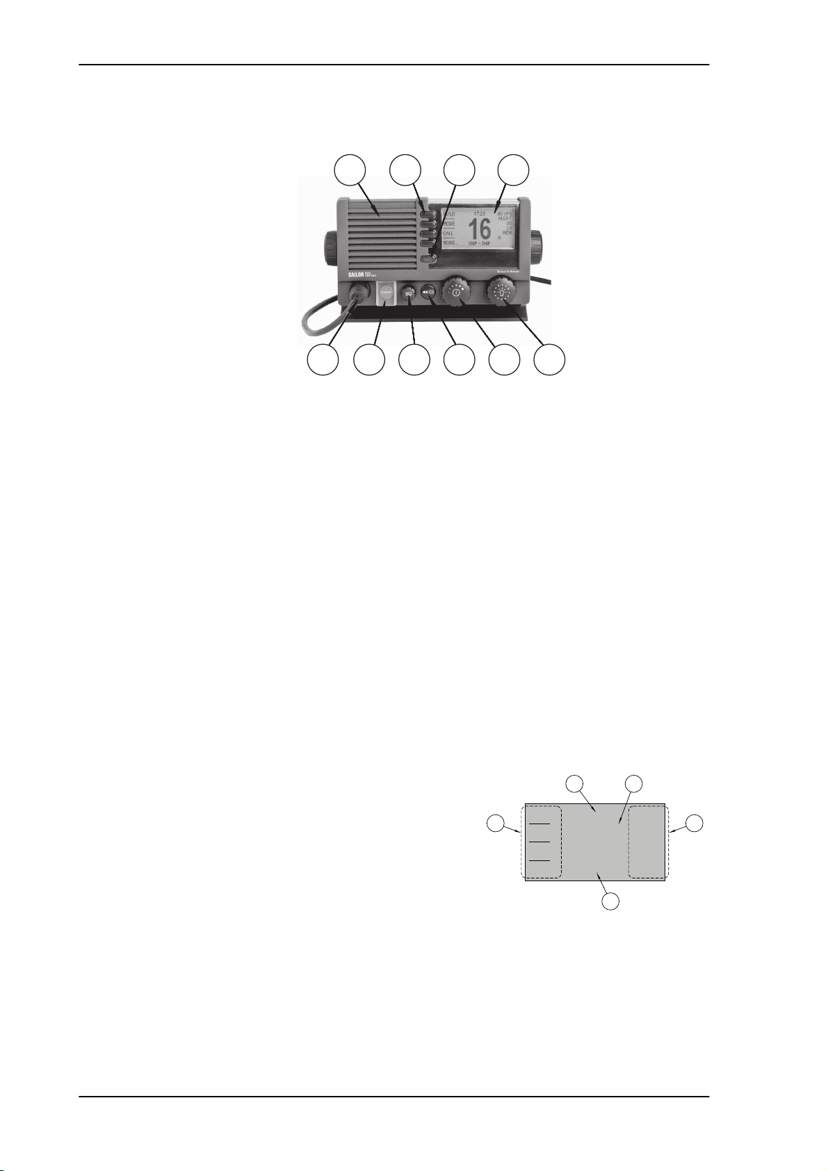
VHF radio with DSC SAILOR 6215/6216 VHF DSC
1
2
3
4
5
WATCH
CALL
US
DISTRESS/CALL
16
GPS Position
HI/LO
MORE...
Controls on the front plate
1
5
Figure 1-1: Controls on the front plate
2
6
7 9
3 4
8
10
1. Loudspeaker.
2. Four soft keys with function title in the display.
3. Quick selection key for channel 16 and the programmed call channel.
4. Large display.
5. Connector for Handmicrophone or handset. If not used, put the cap from the ACC
connector on the front connector to prevent water ingress.
6. Button for sending a DSC Distress alert.
7. Squelch control to mute background noise.
8. Replay button to play back up to 90 s voice message.
9. Volume wheel knob with key-press function for volume control and power on/off.
10.Selector wheel knob with key-press function for changing the working channel,
navigating in menus in the display and backlight dimming.
1.1.1 SAILOR 6215/6216 VHF DSC display
The picture shows the display after start-up. The
display holds various fields of information,
depending on the currently selected function.
1. Action line containing information relevant for
the currently selected function.
2. Current working channel.
3. Functions you can select with the soft keys. If
there are more than 4 functions in the list press the soft key MORE to display further
functions.
4. Status and other values for the current state or VHF channel.
5. Service line containing current temporary information relevant for the current channel
or function.
1-2 Chapter 1: Introduction
For a detailed description of the information shown for each of the functions available see
the chapter First-time power up on page 3-31.

SAILOR 6215/6216 VHF DSC Accessories available
1.2 Accessories available
Accessory Description
1111
SAILOR 6201 Handset
with cradle (additional)
SAILOR 6203 Handset
with cradle
SAILOR 6202 Hand
Microphone
SAILOR 6205 Control
Speaker Microphone
SAILOR 6207
Connection Box for
parallel handsets
One SAILOR 6201 Handset with cradle is
included in the delivery of the SAILOR
6215/6216 VHF DSC. You can connect
another 2 SAILOR 6201 Handsets.
SAILOR 6203 Handset with cradle,
waterproof to IPx6.
You can use the SAILOR 6202 (waterproof to
IPx6 and IPx8) Hand Microphone instead of
the handset.
With the SAILOR 6205 Control Speaker
Microphone you can control the VHF
functions of the SAILOR 6215/6216 VHF
DSC.
The SAILOR 6207 Connection Box including
Connection Cable 406209-941 is used for
easy installation of several SAILOR 6201/03
Handsets/SAILOR 6202 Hand Microphones.
Introduction
SAILOR 6208 Control
Unit Connection Box
Connection cables 5m connection cable for bulkhead mount: Use this cable
The SAILOR 6208 Connection Box including
Connection Cable 406208-941 is used for easy
installation of external equipment and
accessories:
• Max. 1 SAILOR 6205 Control Speaker Microphones
in installations where the SAILOR 6202 Hand Microphone is
not connected directly to the SAILOR 6215/6216 VHF DSC,
but located in a different position (part number: 406209-940).
5m Connection cable, 1x10 pole: Use this cable in
installations when connecting external equipment to the
SAILOR 6215/6216 VHF DSC. This cable is included in the
SAILOR 6207 Connection Box for parallel handsets (part
number: 406209-941).
5 m Connection cable for SAILOR 6205 Control
Speaker Microphone, 1x12 pole (part number: 406204-
940).
Table 1-1: Accessories available
Chapter 1: Introduction 1-3

Accessories available SAILOR 6215/6216 VHF DSC
Accessory Description
SAILOR 6270 External
loudspeaker
SAILOR 6090 Power
Converter 24 V to
12 V DC
If you need an additional external loudspeaker
you can connect a SAILOR 6270 Loudspeaker.
It provides 6 W output power.
The SAILOR 6090 Power Converter is used
to provide 12 V DC for the SAILOR
6215/6216 VHF DSC from a 24 V DC power
source.
Table 1-1: Accessories available (Continued)
1-4 Chapter 1: Introduction

SAILOR 6215/6216 VHF DSC Accessories available
Handset
Microphone
VHF DSC
GPS in (NMEA 0183)
Cable
Service
Loud Hailer (4 ohm)
Speaker (8 ohm)
External
ACC. Port
Power
Handset Option
SAILOR 6205
SAILOR 6201
SAILOR 6201
99-129890-D
SAILOR 6215/6216
Hand Microphone
SAILOR 6202
12V DC
110/220V AC
GPS
GPS,
Control Speaker
SAILOR 6207
Connection Box
for parallel handsets
CTRL
ACC
Chart Plotter
N163S
Aerial
RX/TX
SAILOR 6090
12V Battery
24V DC
Power Converter
1.2.1 System configuration - example
1111
Introduction
Figure 1-2: System configuration - example
Chapter 1: Introduction 1-5

Accessories available SAILOR 6215/6216 VHF DSC
1-6 Chapter 1: Introduction

Chapter 2
Installation 2
In this chapter you find information and guidelines for:
• Unpacking the SAILOR 6215/6216 VHF DSC
• Installing the VHF radio
2222
• Power, VHF antenna and external equipment
2.1 Unpacking the SAILOR 6215/6216 VHF DSC
The following items are included in the delivery of a SAILOR 6215/6216 VHF DSC:
• SAILOR 6215/6216 VHF DSC
• SAILOR 6202 Handmicrophone with spiral cable
• User and installation manual
• Installation guide
• Mounting bracket with two wheel knobs
• Connectors for cables
• Power cables, fittings and fuses
• Packaging material
• Sun screen (click-on) for front plate protection
• Kit for flush mount installation, including gasket
Installation
2-7

Installing the VHF radio SAILOR 6215/6216 VHF DSC
2.2 Installing the VHF radio
You can mount the VHF radio as a desktop, overhead or flush-mounted unit integrated in
the instrument panel.
Provide space enough to access the front panel connectors and for installing a cradle for
the speaking device.
Provide at least 120 mm space at the back of the SAILOR 6215/6216 VHF DSC radio
to allow free air circulation.
Compass safe distance
Make sure that the VHF radio is far enough from any magnetic compass to avoid influence
of the loudspeaker magnet on the compass reading. See the following table for the safe
distance after magnetization between the nearest point of the device and the centre of the
compass at which it will produce a deviation of 0.3°.
Device Safe distance
SAILOR 6215/6216 VHF DSC 1.0 m
SAILOR 6202 Handmicrophone 0.8 m
SAILOR 6090 Power Converter 24 V - 12 V 0,15 m
SAILOR 6207 Connection Box for parallel handsets 0.6 m
SAILOR 6208 Control Unit Connection Box 0.6 m
Table 2-1: Compass safe distance
2-8 Chapter 2: Installation

SAILOR 6215/6216 VHF DSC Installing the VHF radio
2.2.1 SAILOR 6215/6216 VHF DSC with U mounting bracket
The mounting bracket and two knobs are included in the delivery.
Desktop mounting
2222
Installation
Overhead mounting
Figure 2-1: Desktop mounting
Figure 2-2: Overhead mounting
Chapter 2: Installation 2-9

Installing the VHF radio SAILOR 6215/6216 VHF DSC
99-130249
4 x M4 or hole for
self-tapping ø3.9
150mm
53mm
71mm
196mm
23mm
9mm
Mounting with U mounting bracket
To mount the VHF radio as tabletop, do as follows:
1. Find a suitable location for the VHF radio. Check that the space is wide/deep enough to
accommodate the VHF radio.
2. Fasten the bracket with 4 screws (included in the delivery.)
3. Insert the VHF radio in the bracket and fasten it with the two knobs.
4. The display of the VHF radio should be at an angle of approximately 90° to your line of
sight when operating it.
2-10 Chapter 2: Installation
Figure 2-3: Mounting with U mounting bracket

SAILOR 6215/6216 VHF DSC Installing the VHF radio
Remove material from shaded area only!
89mm
177mm
R2.5mm x 4
2.2.2 SAILOR 6215/6216 VHF DSC for flush mount
You can mount the VHF radio to a flat surface, e.g. an instrument panel.The flush mount
installation kit is included in the delivery.
2222
Installation
Figure 2-4: Cutout for flush mount
Important
1. Find a suitable location for the VHF radio. Check that the space is deep enough to
accommodate the VHF radio and an additional min. 120 mm space for cable entry.
2. Keep free distance to allow free air circulation around the VHF radio and to allow
sufficient space for access to cables, see the drawing on this page.
3. Cut out the hole for the VHF radio where you want to mount it. Use the cutting template
in the installation guide.
4. Mount the 4 square nuts M4 in the cabinet, ensure that they are placed correctly so it is
possible to screw in the M4x45 screws.
5. Ensure that the flush mount gasket is placed correctly on the VHF radio.
6. Before mounting the VHF radio be aware that the surface is plane and rigid. If the
surface is not plane and/or rigid (stiff) remove the gasket and seal with silicone sealant
between the VHF radio and the surface.
7. Slide the VHF radio in the cut-out. Place the flush mount bracket and fasten it with the 4
screws M4x45. Make sure the torque does not exceed 1Nm when fastening the screws.
The scaling in the above drawing is not 1:1. Consequently do not
attempt to use a print or copy of this page without checking the
dimensions.
Note
Only use screws supplied with the kit for flush mounting.
Chapter 2: Installation 2-11

Installing the VHF radio SAILOR 6215/6216 VHF DSC
A
A
BB
99-130248
Gasket
Flush Mount Bracket (2 pcs.)
Screw M4x45 TORX 20 (4 pcs.)
Connect to LOUD HAILER
(RED isolation on inner connector)
Connect to EXT. SPEAKER
(WHITE isolation on inner connector)
Connect to POWER +
(RED wire)
Connect to POWER -
(BLUE wire)
Square Nut M4x7x2.2 (4 pcs.)
Max wall thickness 26mm
Figure 2-5: Flush mount details
Note
Firmly tie back and secure any wires not used to avoid the possibility for mutual
shorting or shorting to ground.
2-12 Chapter 2: Installation

SAILOR 6215/6216 VHF DSC Installing the VHF radio
+
+
+
+
99-133089
Ground
24V DC
12V DC
-Vout
+Vin
-Vin
Screen/Ground
NC
NC
+Vout
Remove jumper W301:
Vout = 12.5V
Place jumper W300:
Power Converter is always on
H200
Q304
Q302
Q306
CR301
CR300
R314
W301
W300
CR302
C320 C306
C303
C304
C305
C307
C301
C321
C308
C315
C319
C316
C312
C208
C209
C322
C323
C205
C200
C210
C314
C309
C318
L200
C310
C317
C203
C204
VR301
CR305
VR300
CR303
VR302
R204
R203
R202
R201
R208 R207 R206
Q305
Q303
Q301
Q300
T200
C207
C206
C202
C201
C313
C302
J300
J200
C311
C300
CR200
L300
L301
U300
R338
R337
R336
R335
R334
R328
R329
R330
R331
R333
R332
R327
R326
R325
R324
R313
R307
R320
R309
R310
R312
R319
R300
R305
R302
R304
R306
R301
R303
R317
R316
R308
R311
R321
R322
R323
2.2.3 SAILOR 6090 Power Converter
2222
Installation
Figure 2-6: SAILOR 6090 Power Converter, dimensions
Figure 2-7: Connecting the SAILOR 6090 Power Converter
Chapter 2: Installation 2-13

Installing the VHF radio SAILOR 6215/6216 VHF DSC
2.2.4 SAILOR 6202 Handmicrophone
Handmicrophone with spiral cable and PTT button.
Figure 2-8: Handmicrophone
2-14 Chapter 2: Installation

SAILOR 6215/6216 VHF DSC Power, VHF antenna and external equipment
2.3 Power, VHF antenna and external equipment
2222
1
Figure 2-9: Power, VHF antenna and external equipment
1. ACC connector for accessories
2. CTRL connector for control speaker microphone
3. Power, Loudhailer, foghorn and external speaker
4. VHF antenna
5. Ground stud
2
3 4 5
Installation
Chapter 2: Installation 2-15

Power, VHF antenna and external equipment SAILOR 6215/6216 VHF DSC
1
2
341056
789
2.3.1 ACC connector
Use the connector marked ACC to connect GPS input.
The interface for GPS is NMEA 0183 (EN61 162-1 NMEA0183/ EN61 162-2 NMEA0183
Highspeed).
Connector type: Circular connector, 10pin.
Connection cable with plug, part number 406209-941.
Pin assignment: Connector front view on the VHF radio.
Pin Description Wire color
1 NMEA in+ Brown
2 NMEA in- Blue
3 NMEA out- White
4 NMEA out+ Green
5 Mike 2 Yellow
6 EAR 2 Grey
7 Hook_PTT Pink
8 Battery supply when radio is on Red
9 Internal GND = - Battery Black
10 Internal GND = - Battery Orange — SCREEN (Drain)
Table 2-2: ACC connector
2-16 Chapter 2: Installation

SAILOR 6215/6216 VHF DSC Power, VHF antenna and external equipment
NMEA interface description
2222
Installation
Figure 2-10: NMEA interface description
NMEA interface Specifications
NMEA input:
NMEA output
The NMEA interface supports NMEA 0183 v2.0, v2.1 and v2.3.
The following sentences are supported:
• FSI: All fields are decoded.
• GGA: UTC, "Position", "quality indicator" (indicators 1-5). All other fields are unused.
• GLL: UTC, "Position", "Status" and "mode" (indicators A and D). All other fields are unused.
• GNS: UTC, "Position" and "mode" (indicators A and D). All other fields are unused.
• RMC: UTC, "Position", "Status", "Date" and "mode" (indicators A and D). All other fields are
unused.
Impedance: 600 Ohm
Max. 2mA at min. level of 2V
Load Impedance: > 60 Ohm
Drive load: < 35 mA
Table 2-3: NMEA interface
• ZDA: UTC, "Day", "Month", and "Year". All other fields are unused.
In accordance with the standard EN61162-1:2008 and EN61162-2:1998
Chapter 2: Installation 2-17

Power, VHF antenna and external equipment SAILOR 6215/6216 VHF DSC
Received NMEA sentences except for FSI can be forwarded to NMEA output. As talker the
sentences are streamed when received (with no intervals).
SW revision: 2.00.01
2-18 Chapter 2: Installation

SAILOR 6215/6216 VHF DSC Power, VHF antenna and external equipment
1
2
11
3410
12
5
6
789
2.3.2 CTRL connector for control speaker microphone
Connector type: Circular connector, 12pin.
Pin assignment: Connector front view on the VHF radio:
Pin Description
1 GND for cable screen
2 Internal GND=- Battery
2222
3 Battery supply when radio is on
4 Battery supply when radio is on
5 CAN+
6 CAN-
7 Internal GND = - Battery
8 On/off from Control Speaker Microphone
9 RX out +
10 RX out -
11 TX in +
12 TX in -
Table 2-4: CTRL connector for control speaker microphone
Installation
Chapter 2: Installation 2-19

Power, VHF antenna and external equipment SAILOR 6215/6216 VHF DSC
2.3.3 Power, Loudhailer, foghorn and external speaker
Use the connector marked PWR/EXT to connect power, loudhailer and an external speaker.
The cable for this connector is part of the delivery.
1. Blue wire: Power -
2. Red isolation on inner connector: loudhailer
3. White isolation on inner connector: external speaker
4. Red wire: Power +
Figure 2-11: Power, loudhailer, foghorn and external speaker
Protection against water ingress
Important
You must protect the cable connection with rubber vulcanizing tape as shown in the
pictures below. This protection prevents water seeping into the VHF radio, cable and
connectors.
1
Figure 2-12: Protection against water ingress
2
3 4
1
3
2
4
2-20 Chapter 2: Installation

SAILOR 6215/6216 VHF DSC Power, VHF antenna and external equipment
2.3.4 VHF antenna
Use the connector marked ANT to connect the VHF antenna to the radio with a 50 Ohm
coaxial cable with low loss, e.g. RG214. Install a PL259 plug at the cable end.
Place the antenna as high and clear of obstructions as possible. Make sure that the
horizontal distance to metal parts is minimum 1.5 m (5 ft).
Connector type: female SO239 for PL259 plug.
2.3.5 Ground stud
To ground the radio connect a ground wire from the ground stud of the radio to a suitable
grounding point. Use an appropriately sized wire. The ground stud is located above the VHF
antenna connector.
2222
Installation
Figure 2-13: Ground stud
Chapter 2: Installation 2-21

VHF antenna installation SAILOR 6215/6216 VHF DSC
2.4 VHF antenna installation
The SAILOR 6215/6216 VHF DSC is be installed with only one antenna for VHF RX/TX and
DSC. You can install all commonly available 50 Ohm antennas covering the appropriate
frequency range and providing a VSWR less than 1.5 over this range.
For further details on equipment and antenna installation, see IMOCOMSAR/Circ. 32,
GUIDELINES FOR THE HARMONIZATION OF GMDSS REQUIREMENTS FOR RADIO
INSTALLATIONS ON BOARD SOLAS SHIPS.
2.4.1 Cable requirements
Connect the antennas using a low loss type 50 Ohm coaxial cable, e.g. good quality RG214
or better. IMO-COMSAR/Circ. 32 recommends the use of a double screened type cable (like
e.g. RG214) with a maximum insertion loss of 3dB across the antenna cable installation.
The maximum antenna cable length in the installation depends on the quality of the cable,
i.e. the specified attenuation (dB/m) of the cable of choice at the high end of the VHF
frequency band. As a rule of thumb the cable length using e.g. RG214 coaxial cable should
not exceed 25 m.
2.4.2 VHF RX/TX antenna
In installations with two or more VHF radios it is important to ensure the optimum
performance of these by carefully selecting the antenna positions for both radios. It is
recommended to maximize the RF attenuation between the VHF RX/TX antennas in the
installation. You can ensure this by not having the RX/TX antennas positioned at the same
horizontal level, i.e. the RX/TX antennas for each radio must be installed at shifted
elevations as shown in the following drawing.
If sufficient vertical distance between two or more such antennas cannot be achieved, the
horizontal distance between them is increasingly important for optimum performance. If
there is hardly any vertical separation ensure that there is a minimum of 5 m horizontal
distance between any RX/TX antennas in the installation.
To minimize any increase in VSWR of the VHF RX/TX antenna, install the antenna at a
vertical distance of at least 2 m to any other mast, pole or other RF antennas. Keep VHF
antennas as far away as possible from antenna main beam of any radar and satellite
equipment.
2-22 Chapter 2: Installation

SAILOR 6215/6216 VHF DSC VHF antenna installation
RX/TX
DSC
RX/TX
DSC
No. 1 VHF No. 2 VHF
No. 2 VHF No. 1 VHF
39679
RX/TX
DSC
RX/TX
DSC
No. 1 VHF No. 2 VHF
No. 2 VHF No. 1 VHF
39679
2222
Installation
Figure 2-14: Antenna positioning
Figure 2-15: Antenna positioning 1/2
Chapter 2: Installation 2-23

System setup SAILOR 6215/6216 VHF DSC
2.5 System setup
To change a setting in the SYSTEM SETUP, do as follows:
1. Press the soft key SETUP. If it is not in the display, press the soft key MORE until
SETUP appears.
2. Press the arrow soft key or to advance to SYSTEM SETUP.
3. Turn the selector wheel knob to go to a setting, then press the selector
wheel knob to change the setting.
4. Press EXIT to return to normal radio operation
.
SYSTEM SETUP Description
Inactivity timeout Inactivity time-out to exit functions (e.g. in setup) and
return to the application.
Range: 1 to 30 minutes, in 1 minute steps
Default: 10 min.
NMEA input (baud rate) 4800
Factory Defaults Resets the radio to factory defaults.
SW version Software version of the radio
S/N Serial number of the radio
Password If you need to change the identity of the radio (MMSI
number or ATIS code), contact your local dealer.
Table 2-5: System setup
2-24 Chapter 2: Installation
 Loading...