

COBHAM SAILOR 6210 VHF, SAILOR 6215 VHF, SAILOR 6222 VHF, SAILOR 6216 VHF, SAILOR 6248 VHF Installation Manual
...
SAILOR 6000 VHF Program
Installation manual
SAILOR 6210/6215/6216/6217 VHF
SAILOR 6222/6248/6249 VHF

Record of revisions
Rev. Description Release Date Initials
A Original document March 2012 CMA
B Installation Manual SAILOR 6217 added June 2012 CMA
Program 6000 VHF general - Controls on the front plate,
C
’Comments to prevent wter ingress’ added.
SAILOR 6222 VHF DSC - ’2.5.5 Setup of GPS input from LAN’ added
D Cobham rebranding November 2013 CMA
December 2012 CMA

SAILOR 6210 VHF
Installation manual
Release date: November 15, 2013

SAILOR 6210 VHF
Disclaimer
Any responsibility or liability for loss or damage in connection with the use of this product and the
accompanying documentation is disclaimed by Thrane & Thrane A/S. The information in this manual is
provided for information purposes only, is subject to change without notice and may contain errors or
inaccuracies. Manuals issued by Thrane & Thrane A/S are periodically revised and updated. Anyone
relying on this information should acquire the most current version e.g. from www.cobham.com/satcom
or from the distributor. Thrane & Thrane A/S is not responsible for the content or accuracy of any
translations or reproductions, in whole or in part, of this manual from any other source.
Thrane & Thrane A/S is trading as Cobham SATCOM.
Copyright
© 2013 Thrane & Thrane A/S. All rights reserved. Printed in Denmark.
Trademark Acknowledgements
• SAILOR is a registered trademarks of Thrane & Thrane A/S.
• Other product and company names mentioned in this manual may be trademarks or trade names of
their respective owners.
ii

SAILOR 6210 VHF
Safety warning
The following general safety precautions must be observed during all phases of operation,
service and repair of this equipment. Failure to comply with these precautions or with specific
warnings elsewhere in this manual violates safety standards of design, manufacture and
intended use of the equipment. Thrane & Thrane assumes no liability for the customer's failure
to comply with these requirements.
RF exposure hazards and instructions
Your Thrane & Thrane radio set generates electromagnetic RF (radio frequency) energy when
transmitting. To ensure that you and those around you are not exposed to excessive amounts
of energy and thus to avoid health hazards from excessive exposure to RF energy, all persons
must be at least 3ft (0.9 m) away from the antenna when the radio is transmitting.
Warranty limitation
IMPORTANT - The radio is a sealed waterproof unit (classified IPX8). To create and maintain its
waterproof integrity it was assembled in a controlled environment using special equipment. The
radio is not a user maintainable unit, and under no circumstances should the unit be opened
except by authorized personnel. Unauthorized opening of the unit will invalidate the warranty.
Installation and service
Installation and general service must be done by skilled service personnel.
iii

SAILOR 6210 VHF
Manual overview
This manual has the following chapters:
• Introduction contains a description of the VHF radio.
• Installation explains how to mount the VHF radio and how to connect accessories and external
equipment.
• First-time power up explains how to make and receive voice calls over VHF, including how to use and
set-up the channel scanning, the 2-way loudhailer, fog horn external loudspeaker.
• Service & maintenance contains support information including lists of accessories and a
troubleshooting guide.
Appendices with Technical specifications and System configurations.
iv

SAILOR 6210 VHF Table of Contents
Table of Contents
Chapter 1 Introduction
1.1 VHF radio ................................................................................................................................1-1
1.2 Accessories available .....................................................................................................1-4
Chapter 2 Installation
2.1 Unpacking the SAILOR 6210 VHF .......................................................................2-7
2.2 Installing the VHF radio ..............................................................................................2-8
2.3 Power, VHF antenna and external equipment ........................................2-15
2.4 VHF antenna installation .........................................................................................2-22
2.5 System setup ....................................................................................................................2-24
2.6 SAILOR 6201 Handset cradle (optional) ......................................................2-24
2.7 Accessories .........................................................................................................................2-25
Chapter 3 First-time power up
3.1 General use and navigation ...................................................................................3-31
Chapter 4 Service & maintenance
4.1 Contact for support .....................................................................................................4-33
4.2 Maintenance ......................................................................................................................4-33
4.3 Returning units for repair ........................................................................................4-36
Appendix A Technical specifications
A.1 SAILOR 6210 VHF ........................................................................................................ A-37
Appendix B System configurations
B.1 System configuration examples ........................................................................B-39
B.2 Cable requirements ......................................................................................................B-43
Glossary ...........................................................................................................................................................Glossary-47
Index ................................................................................................................................................................ Index-49
v

Table of Contents SAILOR 6210 VHF
vi

SAILOR 6210 VHF
List of figures
Figure 1-1: Controls on the front plate...........................................................................................................................1-2
Figure 1-2: System configuration - example................................................................................................................1-6
Figure 2-1: Desktop mounting ............................................................................................................................................2-9
Figure 2-2: Overhead mounting .........................................................................................................................................2-9
Figure 2-3: Mounting with U mounting bracket...................................................................................................... 2-10
Figure 2-4: Flush mount ......................................................................................................................................................2-11
Figure 2-5: Cutout for flush mount................................................................................................................................ 2-11
Figure 2-6: Flush mount details .......................................................................................................................................2-12
Figure 2-7: SAILOR 6090 Power Converter, dimensions.....................................................................................2-13
Figure 2-8: Connecting the SAILOR 6090 Power Converter .............................................................................2-13
Figure 2-9: Handmicrophone............................................................................................................................................ 2-14
Figure 2-10: Power, VHF antenna and external equipment..................................................................................2-15
Figure 2-11: External DSC controller ...............................................................................................................................2-16
Figure 2-12: NMEA interface description...................................................................................................................... 2-17
Figure 2-13: Power, loudhailer, foghorn and external speaker............................................................................2-20
Figure 2-14: Protection against water ingress.............................................................................................................2-20
Figure 2-15: Ground stud.......................................................................................................................................................2-21
Figure 2-16: Antenna positioning......................................................................................................................................2-23
Figure 2-17: Antenna positioning 1/2 .............................................................................................................................2-23
Figure 2-18: Handset. ..............................................................................................................................................................2-24
Figure 2-19: SAILOR 6207 Connection Box for parallel handsets, mounting.............................................. 2-26
Figure 2-20: Connection Box for parallel handsets, wiring ...................................................................................2-26
Figure 2-21: SAILOR 6207 Connection Box for parallel handsets, diagram .................................................2-27
Figure 2-22: SAILOR 6208 Control Unit Connection Box, mounting ..............................................................2-28
Figure 2-23: SAILOR 6208 Control Unit Connection Box for parallel handsets, wiring..........................2-28
Figure 2-24: SAILOR 6208 Control Unit Connection Box, diagram..................................................................2-29
Figure 4-1: Fuse in the SAILOR 6090 Power Converter.......................................................................................4-35
Figure B-1: How to install a SAILOR 6204 CSM far from the VHF..................................................................B-40
Figure B-2: How to install a SAILOR 6204 close to the VHF radio..................................................................B-41
Figure B-3: How to install a SAILOR 6204 very close to the VHF radio .......................................................B-42
vii

SAILOR 6210 VHF
viii

SAILOR 6210 VHF
List of tables
Table 1-1: Accessories available .......................................................................................................................................1-4
Table 2-1: Compass safe distance ...................................................................................................................................2-8
Table 2-2: ACC connector ................................................................................................................................................2-16
Table 2-3: NMEA interface............................................................................................................................................... 2-17
Table 2-4: CTRL connector for control speaker microphone ..........................................................................2-19
Table 2-5: System setup .................................................................................................................................................... 2-24
Table 2-6: Part numbers for accessories....................................................................................................................2-25
Table 4-1: Troubleshooting guide................................................................................................................................. 4-33
Table A-1: Technical specifications..............................................................................................................................A-37
Table B-1: Cable overview ................................................................................................................................................B-43
Table B-2: Cable specifications for cable 2...............................................................................................................B-44
Table B-3: Cable specifications for cable 8 (CTRL) ...............................................................................................B-44
ix

SAILOR 6210 VHF
x
Chapter 1
Introduction 1
1111
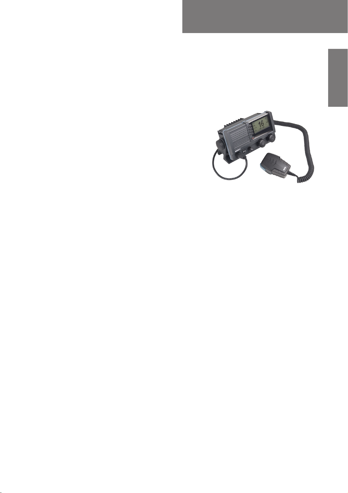
1.1 VHF radio
SAILOR 6210 VHF is approved to R&TTE and is
waterproof to the IPx8 and IPx6 standard. As
part of the safety equipment, use the SAILOR
6210 VHF in an emergency situation. However
the best way to guarantee functionality in an
emergency situation, is to use the radio in daily
communication on board.
The VHF radio is a simplex/semi duplex VHF
radio. It is designed with an easy-to-use menudriven setup. You use the soft-keys to enter the
desired functions, you browse and select a
setting using the right selection wheel knob. The large display has red adjustable backlight
which provides a good visibility even at night and protects your night vision.
The VHF radio can replay the last 90 s of received voice. This is a useful feature to minimize
misunderstandings and to record messages when the radio is unattended.
The VHF radio connects easily to external equipment like a 2-way loudhailer and an
external speaker. You can use the loudhailer as a 2-way on-board communicator. The
loudhailer also functions as a fog horn. You can select from several programmed fog-horn
patterns.
Introduction
For a list of other accessories available for the SAILOR 6210 VHF check with your nearest
distributor.
1-1
VHF radio SAILOR 6210 VHF
1
23
4
5
HI/LO
WATCH
SCAN
INT
DUAL WATCH
SHIP - SHIP
16
MORE...
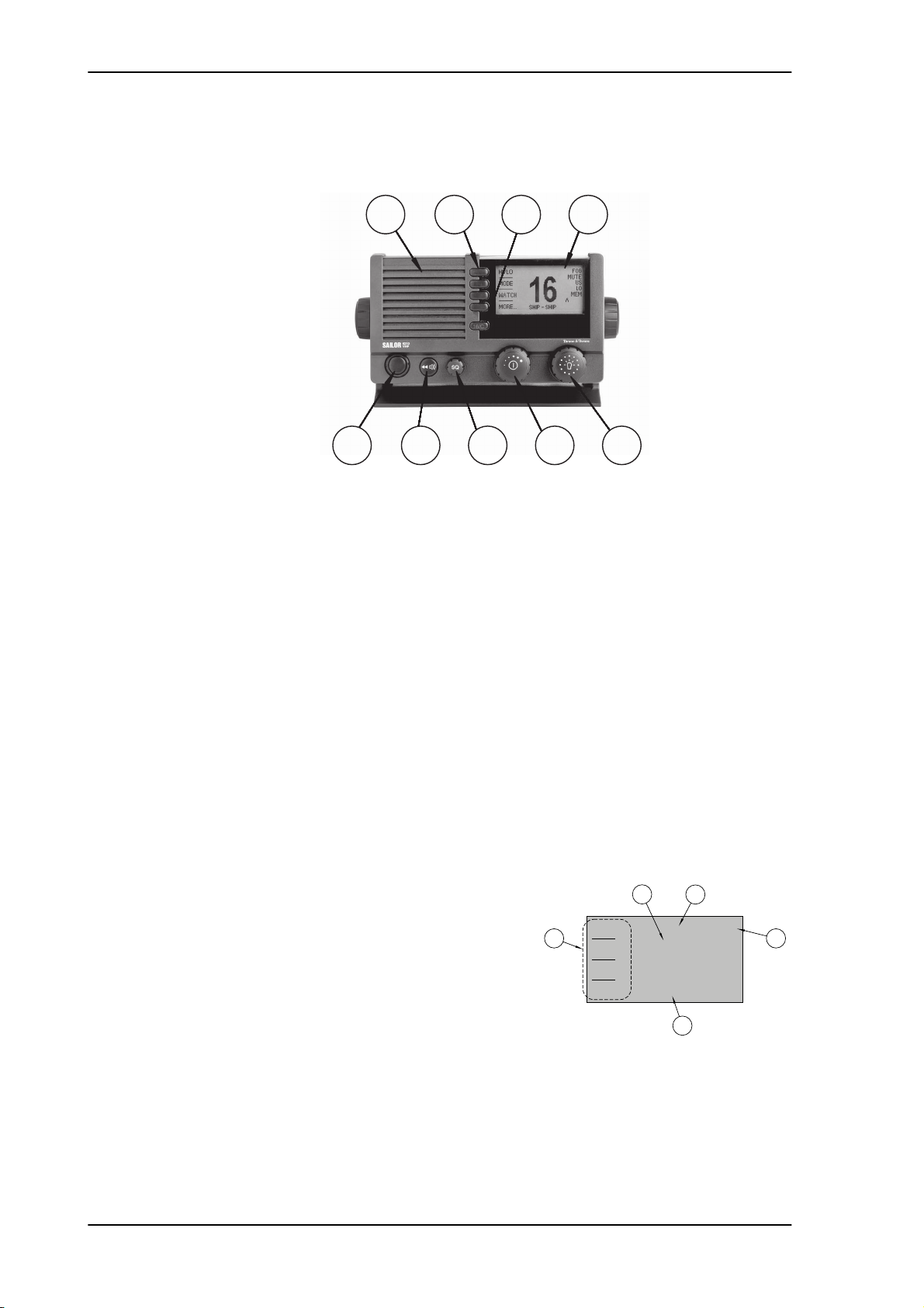
Controls on the front plate
1
5
Figure 1-1: Controls on the front plate
2
7
3 4
6 8 9
1. Loudspeaker.
2. Four soft keys with function title in the display.
3. Quick selection key for channel 16 and the programmed call channel.
4. Large display.
5. Connector for Handmicrophone or handset. If not used, put the cap from the ACC
connector on the front connector to prevent water ingress.
6. Squelch control to mute background noise.
7. Replay button to play back up to 90 s voice message.
8. Volume wheel knob with key-press function for volume control and power on/off.
9. Selector wheel knob with key-press function for changing the working channel,
navigating in menus in the display and backlight dimming.
1.1.1 SAILOR 6210 VHF display
The picture shows the display after start-up.The
display holds various fields of information,
depending on the currently selected function.
1. Current working channel.
2. Functions you can select with the soft keys. If
there are more than 4 functions in the list press
the soft key MORE to display further functions.
3. Status and other values for the current state or
VHF channel.
4. Service line containing current temporary information relevant for the current channel
or function.
5. Action line containing current state or temporary information relevant for the
currently selected function.
1-2 Chapter 1: Introduction

SAILOR 6210 VHF VHF radio
For a detailed description of the information shown for each of the functions available see
the chapter First-time power up on page 3-31.
1111
Introduction
Chapter 1: Introduction 1-3
Accessories available SAILOR 6210 VHF
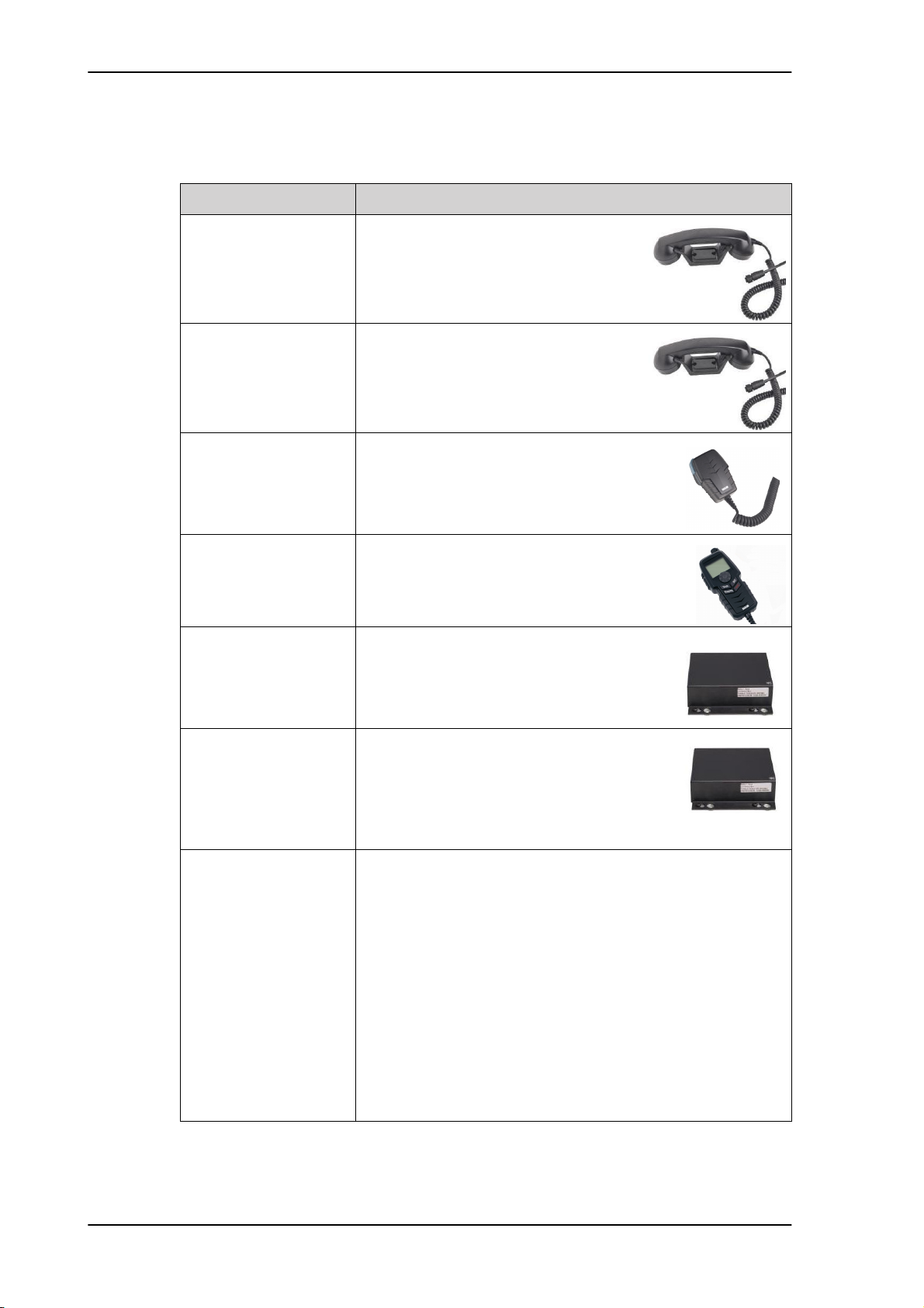
1.2 Accessories available
Accessory Description
SAILOR 6201 Handset
with cradle (additional)
SAILOR 6203 Handset
with cradle
SAILOR 6202 Hand
Microphone
SAILOR 6204 Control
Speaker Microphone
SAILOR 6207
Connection Box for
parallel handsets
One SAILOR 6201 Handset with cradle is
included in the delivery of the SAILOR
6210 VHF. You can connect another 2
SAILOR 6201 Handsets.
SAILOR 6203 Handset with cradle,
waterproof to IPx6.
You can use the SAILOR 6202 (waterproof to
IPx6 and IPx8) Hand Microphone instead of
the handset.
With the SAILOR 6204 Control Speaker
Microphone you can control the VHF
functions of the SAILOR 6210 VHF.
The SAILOR 6207 Connection Box including
Connection Cable 406209-941 is used for
easy installation of several SAILOR 6201/03
Handsets/SAILOR 6202 Hand Microphones.
SAILOR 6208 Control
Unit Connection Box
Connection cables 5m connection cable for bulkhead mount: Use this cable
The SAILOR 6208 Connection Box including
Connection Cable 406208-941 is used for easy
installation of external equipment and
accessories:
• Max. 1 SAILOR 6204 Control Speaker Microphones
in installations where the SAILOR 6202 Hand Microphone is
not connected directly to the SAILOR 6210 VHF, but located
in a different position (part number: 406209-940).
5m Connection cable, 1x10 pole: Use this cable in
installations when connecting external equipment to the
SAILOR 6210 VHF. This cable is included in the SAILOR 6207
Connection Box for parallel handsets (part number: 406209-
941).
5 m Connection cable for SAILOR 6204 Control
Speaker Microphone, 1x12 pole (part number: 406204-
940).
Table 1-1: Accessories available
1-4 Chapter 1: Introduction

SAILOR 6210 VHF Accessories available
Accessory Description
1111
SAILOR 6270 External
loudspeaker
SAILOR 6090 Power
Converter 24 V to
12 V DC
If you need an additional external loudspeaker
you can connect a SAILOR 6270 Loudspeaker.
It provides 6 W output power.
Introduction
The SAILOR 6090 Power Converter is used
to provide 12 V DC for the SAILOR 6210
VHF from a 24 V DC power source.
Table 1-1: Accessories available (Continued)
Chapter 1: Introduction 1-5
Accessories available SAILOR 6210 VHF
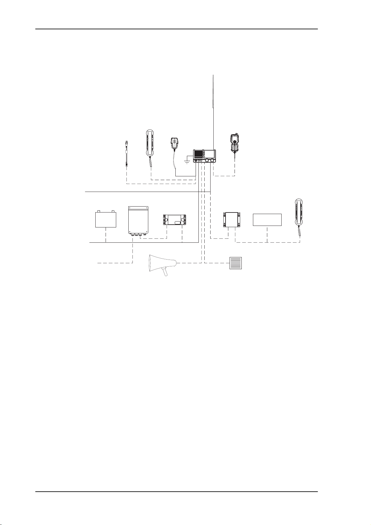
Handset
Microphone
DSC modem
Cable
Service
Loud Hailer (4 ohm)
Speaker (8 ohm)
External
ACC. Port
Power
Handset Option
SAILOR 6204
SAILOR 6201
SAILOR 6201
Hand Microphone
SAILOR 6202
12V DC
110/220V AC
GPS
External
Control Speaker
SAILOR 6207
Connection Box
for parallel handsets
VHF
SAILOR 6210
99-130265-B
N163S
Aerial
RX/TX
SAILOR 6090
12V Battery
24V DC
Power Converter
1.2.1 System configuration - example
Figure 1-2: System configuration - example
1-6 Chapter 1: Introduction

Chapter 2
Installation 2
In this chapter you find information and guidelines for:
• Unpacking the SAILOR 6210 VHF
• Installing the VHF radio
2222
• Power, VHF antenna and external equipment
2.1 Unpacking the SAILOR 6210 VHF
The following items are included in the delivery of a SAILOR 6210 VHF:
• SAILOR 6210 VHF
• SAILOR 6202 Handmicrophone with spiral cable
• User and installation manual
• Installation guide
• Mounting bracket with two wheel knobs
• Connectors for cables
• Power cables, fittings and fuses
• Packaging material
• Sun screen (click-on) for front plate protection
• Kit for flush mount installation, including gasket
Installation
2-7
Installing the VHF radio SAILOR 6210 VHF
2.2 Installing the VHF radio
You can mount the VHF radio as a desktop, overhead or flush-mounted unit integrated in
the instrument panel.
Provide space enough to access the front panel connectors and for installing a cradle for
the speaking device.
Provide at least 120 mm space at the back of the SAILOR 6210 VHF radio to allow free
air circulation.
Compass safe distance
Make sure that the VHF radio is far enough from any magnetic compass to avoid influence
of the loudspeaker magnet on the compass reading. See the following table for the safe
distance after magnetization between the nearest point of the device and the centre of the
compass at which it will produce a deviation of 0.3°.
Device Safe distance
SAILOR 6210 VHF 1.0 m
SAILOR 6202 Handmicrophone 0.8 m
SAILOR 6090 Power Converter 24 V - 12 V 0,15 m
SAILOR 6207 Connection Box for parallel handsets 0.6 m
SAILOR 6208 Control Unit Connection Box 0.6 m
Table 2-1: Compass safe distance
2-8 Chapter 2: Installation
SAILOR 6210 VHF Installing the VHF radio
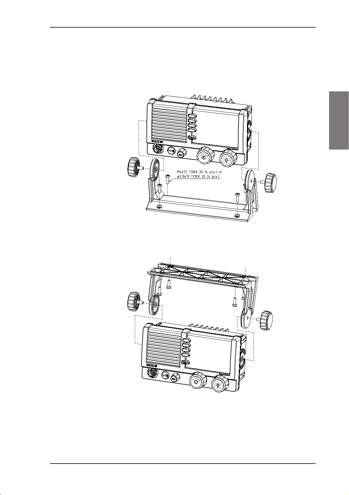
2.2.1 SAILOR 6210 VHF with U mounting bracket
The mounting bracket and two knobs are included in the delivery.
Desktop mounting
2222
Installation
Overhead mounting
Figure 2-1: Desktop mounting
Figure 2-2: Overhead mounting
Chapter 2: Installation 2-9
Installing the VHF radio SAILOR 6210 VHF
99-130249
4 x M4 or hole for
self-tapping ø3.9
150mm
53mm
71mm
196mm
23mm
9mm
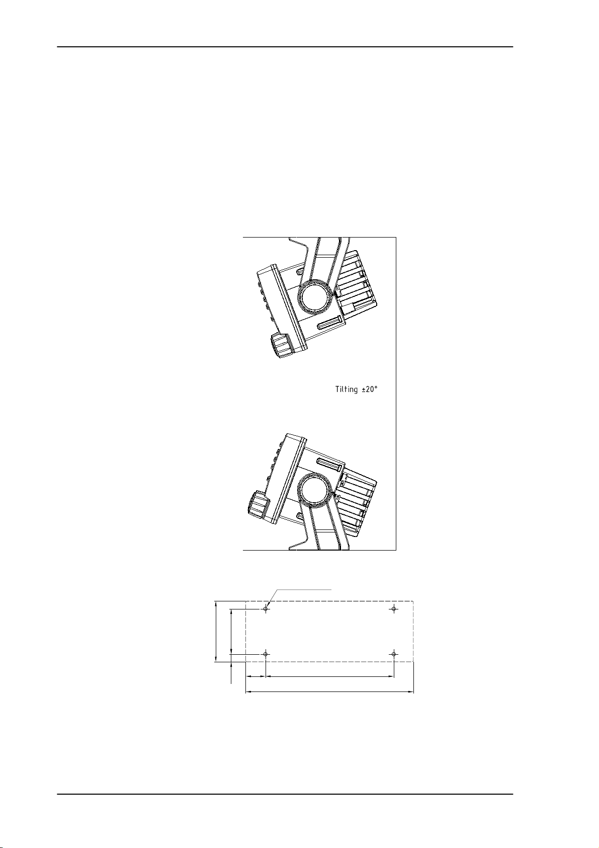
Mounting with U mounting bracket
To mount the VHF radio as tabletop, do as follows:
1. Find a suitable location for the VHF radio. Check that the space is wide/deep enough to
accommodate the VHF radio.
2. Fasten the bracket with 4 screws (included in the delivery.)
3. Insert the VHF radio in the bracket and fasten it with the two knobs.
4. The display of the VHF radio should be at an angle of approximately 90° to your line of
sight when operating it.
2-10 Chapter 2: Installation
Figure 2-3: Mounting with U mounting bracket
SAILOR 6210 VHF Installing the VHF radio
Remove material from shaded area only!
89mm
177mm
R2.5mm x 4
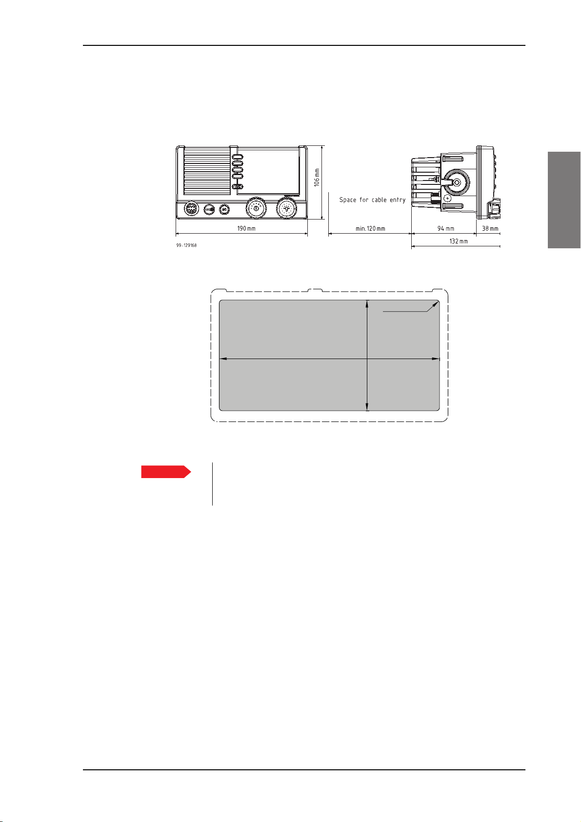
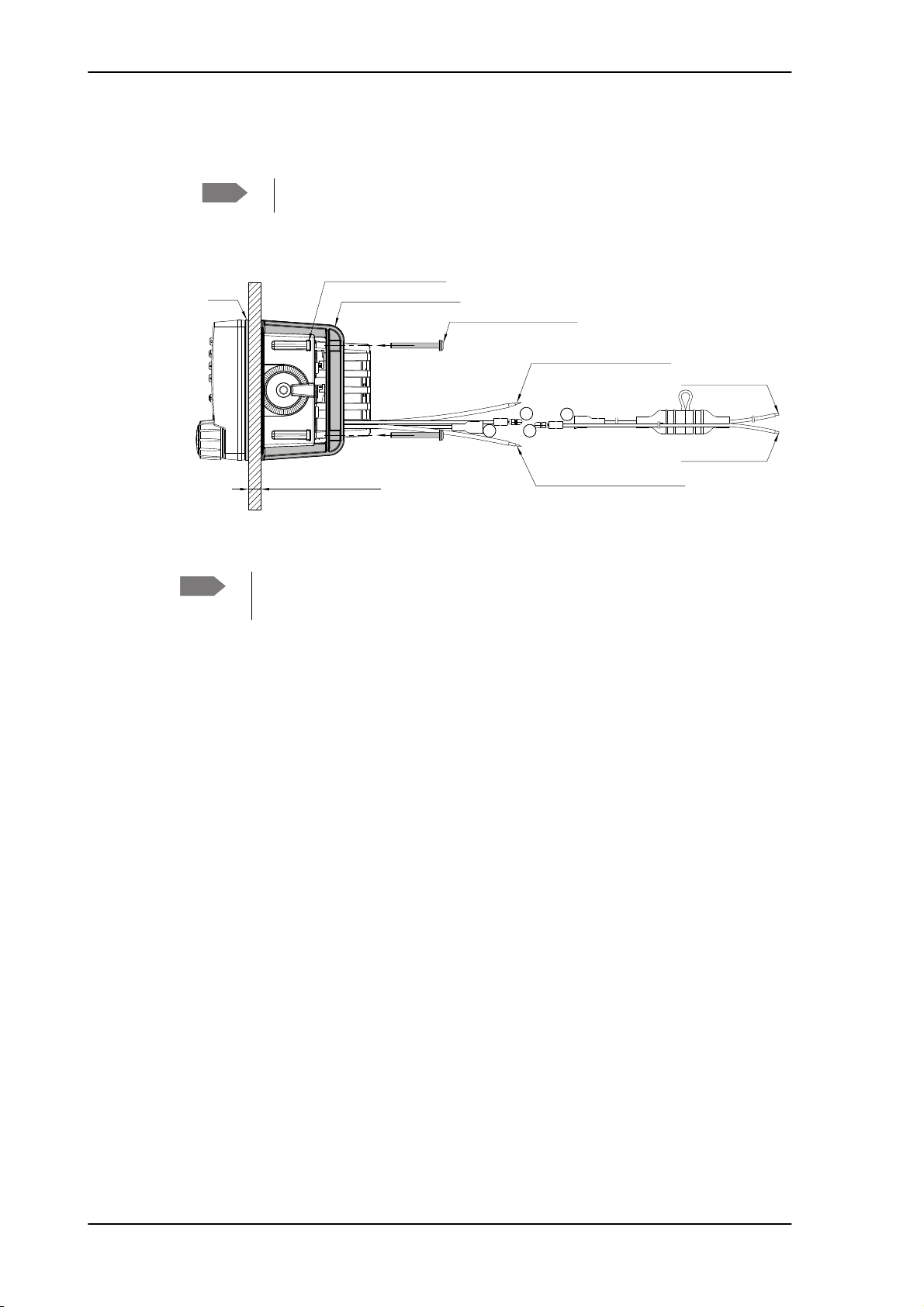
2.2.2 SAILOR 6210 VHF for flush mount
You can mount the VHF radio to a flat surface, e.g. an instrument panel.The flush mount
installation kit is included in the delivery.
Figure 2-4: Flush mount
2222
Installation
Figure 2-5: Cutout for flush mount
Important
1. Find a suitable location for the VHF radio. Check that the space is deep enough to
accommodate the VHF radio and an additional min. 120 mm space for cable entry.
2. Keep free distance to allow free air circulation around the VHF radio and to allow
sufficient space for access to cables, see the drawing on this page.
3. Cut out the hole for the VHF radio where you want to mount it. Use the cutting template
in the installation guide.
4. Mount the 4 square nuts M4 in the cabinet, ensure that they are placed correctly so it is
possible to screw in the M4x45 screws.
5. Ensure that the flush mount gasket is placed correctly on the VHF radio.
6. Before mounting the VHF radio be aware that the surface is plane and rigid. If the
surface is not plane and/or rigid (stiff) remove the gasket and seal with silicone sealant
between the VHF radio and the surface.
The scaling in the above drawing is not 1:1. Consequently do not
attempt to use a print or copy of this page without checking the
dimensions.
Chapter 2: Installation 2-11
Installing the VHF radio SAILOR 6210 VHF
A
A
BB
99-130248
Gasket
Flush Mount Bracket (2 pcs.)
Screw M4x45 TORX 20 (4 pcs.)
Connect to LOUD HAILER
(RED isolation on inner connector)
Connect to EXT. SPEAKER
(WHITE isolation on inner connector)
Connect to POWER +
(RED wire)
Connect to POWER -
(BLUE wire)
Square Nut M4x7x2.2 (4 pcs.)
Max wall thickness 26mm
7. Slide the VHF radio in the cut-out. Place the flush mount bracket and fasten it with the 4
screws M4x45. Make sure the torque does not exceed 1Nm when fastening the screws.
Note
Note
Only use screws supplied with the kit for flush mounting.
Figure 2-6: Flush mount details
Firmly tie back and secure any wires not used to avoid the possibility for mutual
shorting or shorting to ground.
2-12 Chapter 2: Installation
SAILOR 6210 VHF Installing the VHF radio
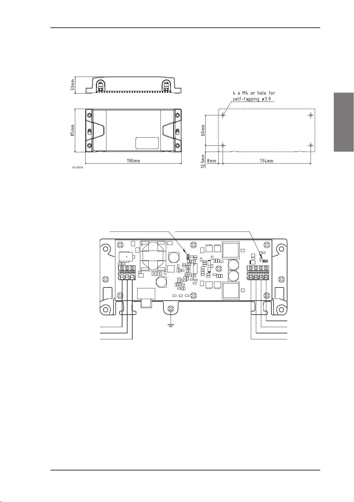
+
+
+
+
99-133089
Ground
24V DC
12V DC
-Vout
+Vin
-Vin
Screen/Ground
NC
NC
+Vout
Remove jumper W301:
Vout = 12.5V
Place jumper W300:
Power Converter is always on
H200
Q304
Q302
Q306
CR301
CR300
R314
W301
W300
CR302
C320 C306
C303
C304
C305
C307
C301
C321
C308
C315
C319
C316
C312
C208
C209
C322
C323
C205
C200
C210
C314
C309
C318
L200
C310
C317
C203
C204
VR301
CR305
VR300
CR303
VR302
R204
R203
R202
R201
R208 R207 R206
Q305
Q303
Q301
Q300
T200
C207
C206
C202
C201
C313
C302
J300
J200
C311
C300
CR200
L300
L301
U300
R338
R337
R336
R335
R334
R328
R329
R330
R331
R333
R332
R327
R326
R325
R324
R313
R307
R320
R309
R310
R312
R319
R300
R305
R302
R304
R306
R301
R303
R317
R316
R308
R311
R321
R322
R323
2.2.3 SAILOR 6090 Power Converter
2222
Installation
Figure 2-7: SAILOR 6090 Power Converter, dimensions
Figure 2-8: Connecting the SAILOR 6090 Power Converter
Chapter 2: Installation 2-13
Installing the VHF radio SAILOR 6210 VHF
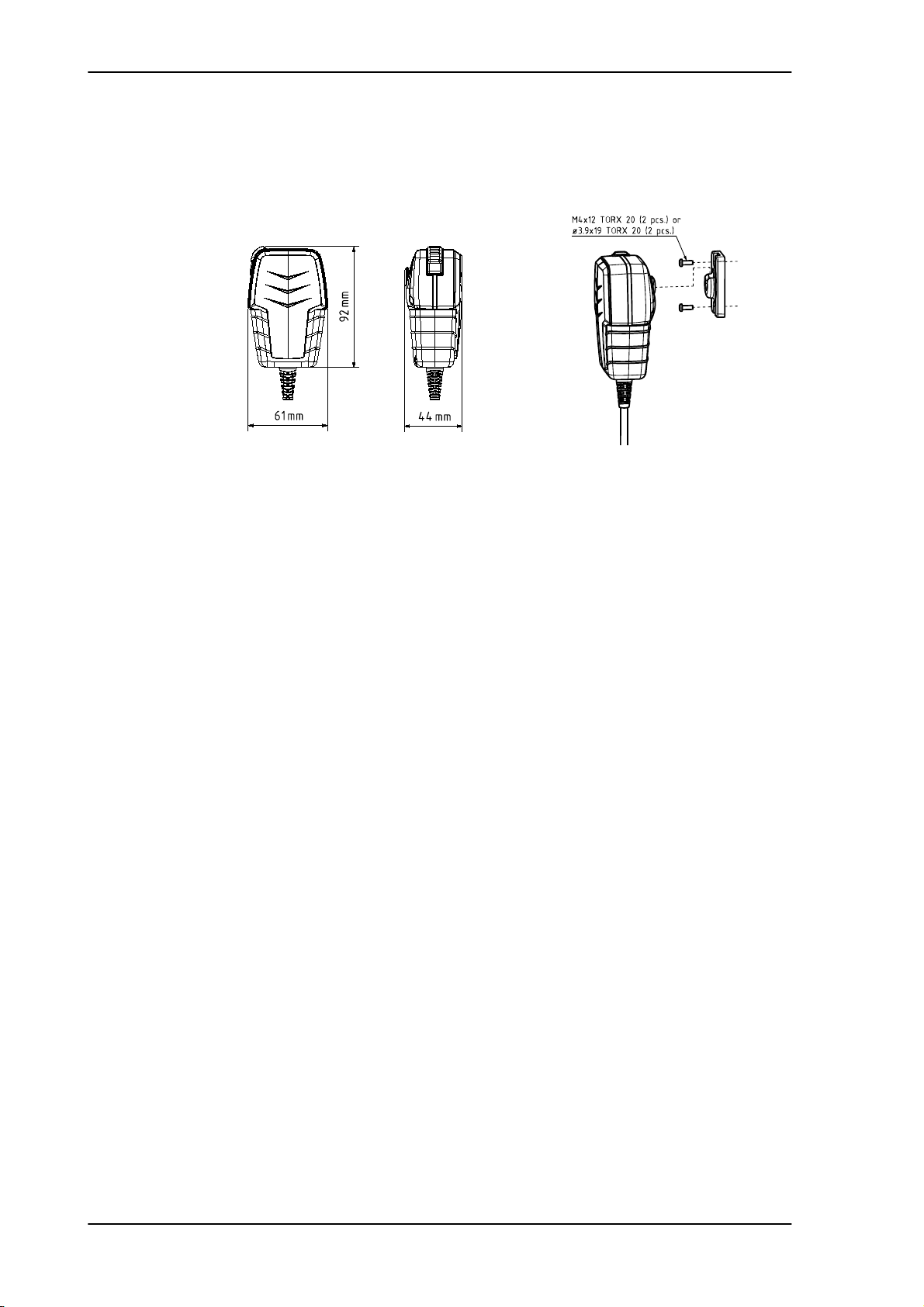
2.2.4 SAILOR 6202 Handmicrophone
Handmicrophone with spiral cable and PTT button.
Figure 2-9: Handmicrophone
2-14 Chapter 2: Installation
SAILOR 6210 VHF Power, VHF antenna and external equipment
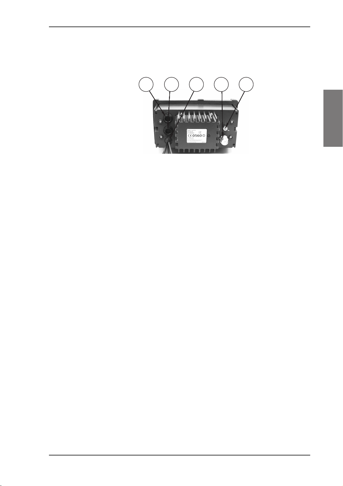
2.3 Power, VHF antenna and external equipment
2222
1
Figure 2-10: Power, VHF antenna and external equipment
1. ACC connector for accessories
2. CTRL connector for control speaker microphone
3. Power, Loudhailer, foghorn and external speaker
4. VHF antenna
5. Ground stud
2
3 4 5
Installation
Chapter 2: Installation 2-15
Power, VHF antenna and external equipment SAILOR 6210 VHF
1
2
341056
789
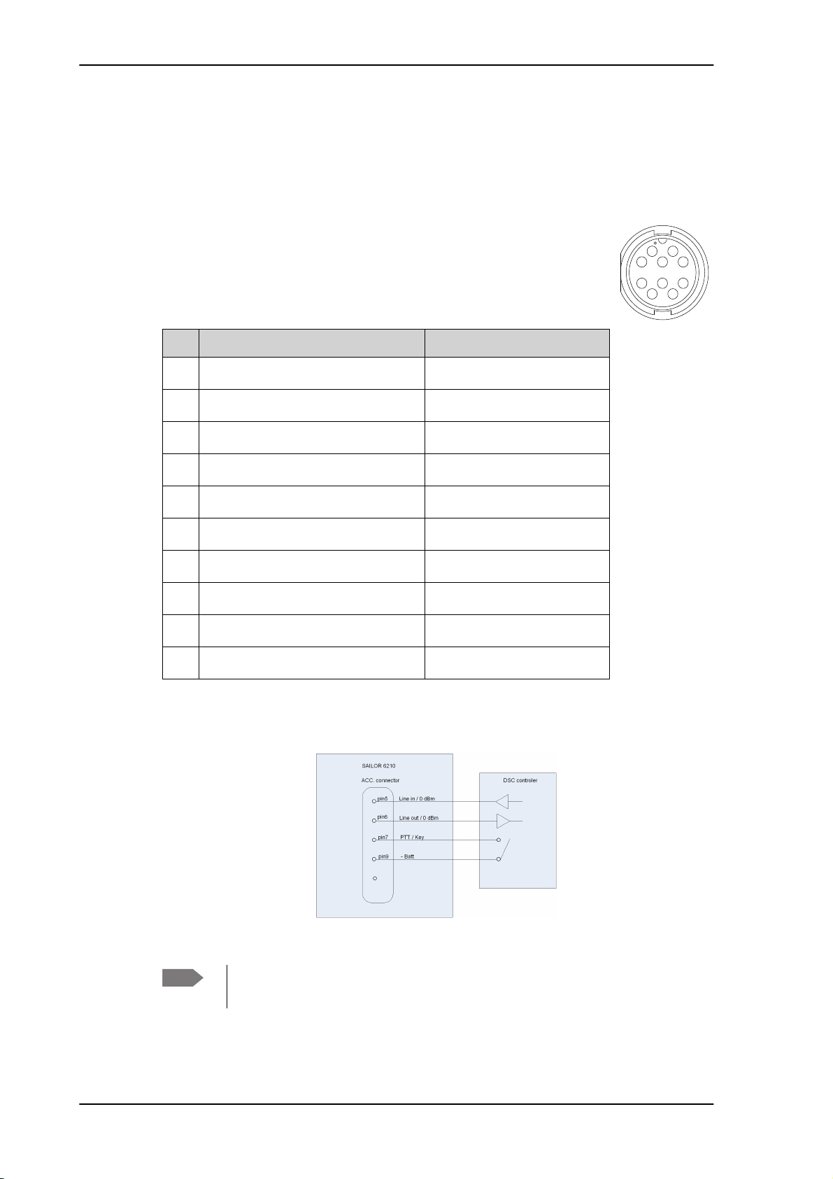
2.3.1 ACC connector
Use the connector marked ACC to connect GPS input.
The interface for GPS is NMEA 0183 (EN61 162-1 NMEA0183/ EN61 162-2 NMEA0183
Highspeed).
Connector type: Circular connector, 10pin.
Connection cable with plug, part number 406209-941.
Pin assignment: Connector front view on the VHF radio.
Pin Description Wire color
1 NMEA in+ Brown
2 NMEA in- Blue
3 NMEA out- White
4 NMEA out+ Green
5 Mike 2 / Line in Yellow
6 EAR 2 / Line out Grey
7 Hook_PTT Pink
8 Battery supply when radio is on Red
9 Internal GND = - Battery Black
10 Internal GND = - Battery Orange — SCREEN (Drain)
Table 2-2: ACC connector
External DSC controller
Figure 2-11: External DSC controller
Note
To achieve the 0dBm signal level on the Line Out pin the Handset 2 earpiece
volume must be configured to level 14 (max).
2-16 Chapter 2: Installation
SAILOR 6210 VHF Power, VHF antenna and external equipment
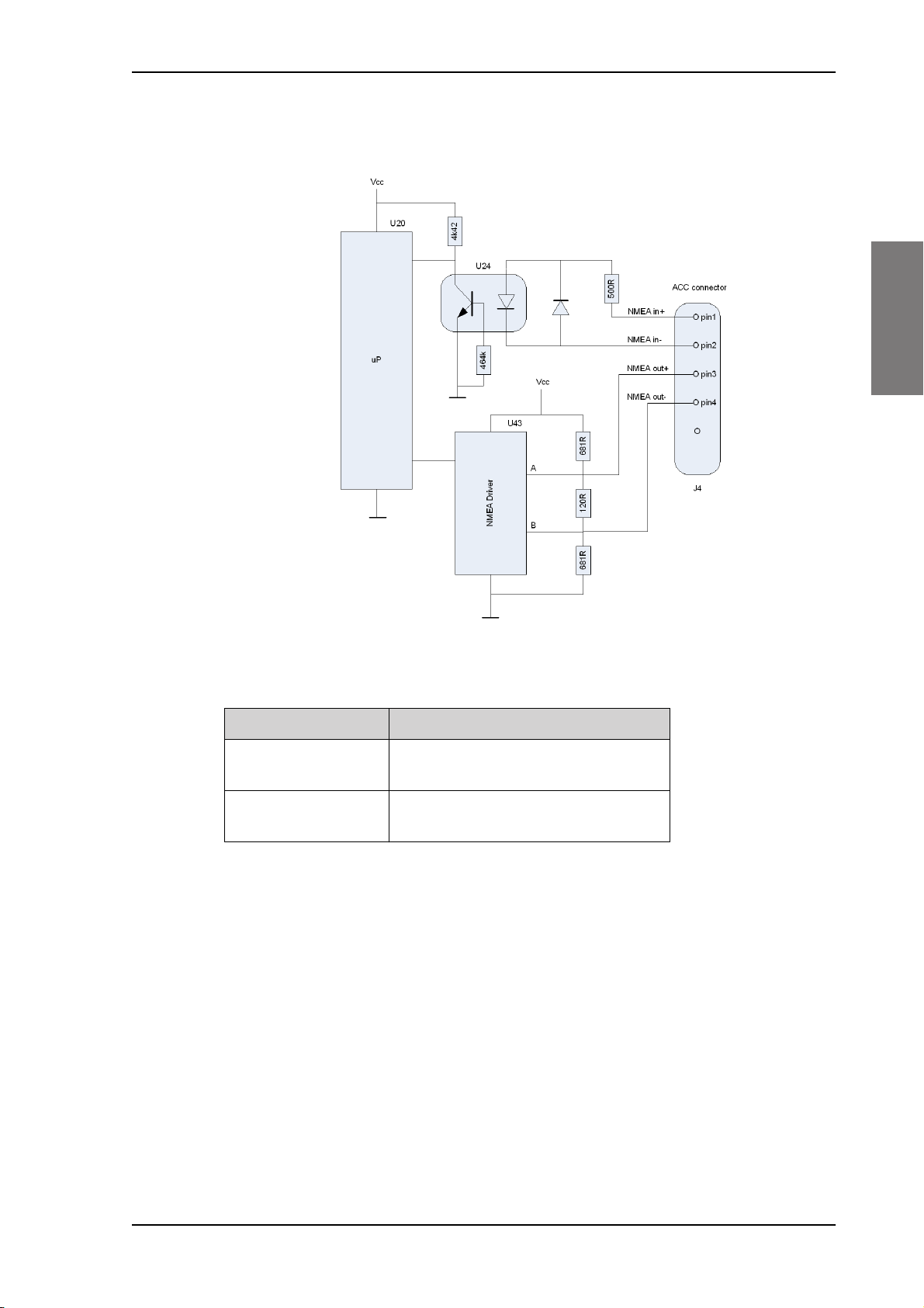
NMEA interface description
2222
Installation
Figure 2-12: NMEA interface description
NMEA interface Specifications
NMEA input:
NMEA output
The NMEA interface supports NMEA 0183 v2.0, v2.1 and v2.3.
The following sentences are supported:
• FSI: All fields are decoded.
• GGA: UTC, "Position", "quality indicator" (indicators 1-5). All other fields are unused.
• GLL: UTC, "Position", "Status" and "mode" (indicators A and D). All other fields are unused.
• GNS: UTC, "Position" and "mode" (indicators A and D). All other fields are unused.
• RMC: UTC, "Position", "Status", "Date" and "mode" (indicators A and D). All other fields are
unused.
Impedance: 600 Ohm
Max. 2mA at min. level of 2V
Load Impedance: > 60 Ohm
Drive load: < 35 mA
Table 2-3: NMEA interface
• ZDA: UTC, "Day", "Month", and "Year". All other fields are unused.
In accordance with the standard EN61162-1:2008 and EN61162-2:1998
Chapter 2: Installation 2-17

Power, VHF antenna and external equipment SAILOR 6210 VHF
Received NMEA sentences except for FSI can be forwarded to NMEA output. As talker the
sentences are streamed when received (with no intervals).
HW revision: 57-127367-D.02
SW revision: 2.00.01
2-18 Chapter 2: Installation
 Loading...