

COBHAM SAILOR 600 VSAT Ka Installation Manual
SAILOR 600 VSAT Ka
Installation manual
SAILOR 600 VSAT Ka
Important
Quick guide
Configuration tasks (minimum)
This quick guide aims at experienced service personnel who have installed the SAILOR 600 VSAT Ka
system and connected power. It lists the minimum configuration tasks you have to make before the
system can be used on-air on a satellite.
1. Switch on the Antenna Control Unit only.
Do not switch on the modem at this point.
2. Connect a PC to the front LAN connector or the LAN3 connector at the rear of the Antenna Control
Unit.
3. Open an Internet Browser to access the SAILOR 600 VSAT Ka: IP address: http://192.168.0.1 (default),
user name: admin, password: 1234.
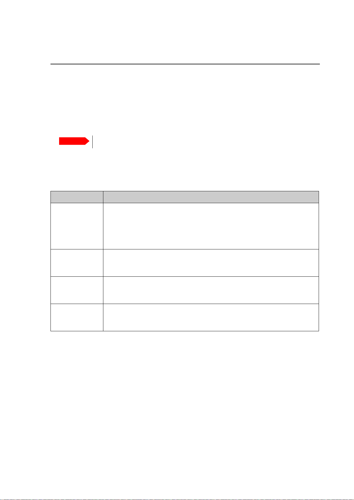
Configuration task What to do and where to find more information
Heading input
Azimuth
calibration
Cable calibration
Satellite profile
4. Switch on the modem and wait for the modem to boot and perform the initial BUC calibration.
5. Verify that the SAILOR 600 VSAT Ka acquires the Ka satellite (ACU display shows ACQUISITION).
6. Verify that the system is operational. The status in the ACU display must show TRACKING and the
upper status line MDM: NETOK.
Configure the heading input to External under SETTINGS > Navigation. For
more information see Select the desired heading input, see the following table.
on page 6-3.
Connect the ship’s heading (NMEA0183, RS-422/RS-232) to the NMEA 0183
multi-connector. For more information see NMEA 0183 connector on page 4-3.
Make an azimuth calibration under SERVICE > Calibration to ensure that the
antenna can point and receive a signal from the satellite. For more information see
Calibration on page 6-7.
Make a cable calibration under SERVICE > Calibration to ensure that the cable
loss is calculated properly. For more information see Cable calibration on page 6-
11.
A satellite profile with the iDirect X7 Modem is already set up at the factory. No
further profiles are needed. Activate the satellite profile under SETTINGS >
Satellite profiles. For more information see Satellite profiles on page 6-19.
98-148248-A

SAILOR 600 VSAT Ka
Installation manual
Document number: 98-148248-A
Release date:
3k November 2015

Disclaimer
Any responsibility or liability for loss or damage in connection with the use of this product and the
accompanying documentation is disclaimed by Thrane & Thrane A/S. The information in this manual is
provided for information purposes only, is subject to change without notice and may contain errors or
inaccuracies. Manuals issued by Thrane & Thrane A/S are periodically revised and updated. Anyone
relying on this information should acquire the most current version e.g. from www.cobham.com/satcom,
Service and support, or from the distributor. Thrane & Thrane A/S is not responsible for the content or
accuracy of any translations or reproductions, in whole or in part, of this manual from any other source.
In the event of any discrepancies, the English version shall be the governing text.
Thrane & Thrane A/S is trading as Cobham SATCOM.
Copyright
© 2015 Thrane & Thrane A/S. All rights reserved.
Trademark acknowledgements
• Some product and company names mentioned in this manual may be trademarks or trade names of
their respective owners.
GPL notification
The software included in this product contains copyrighted software that is licensed under the GPL/LGPL.
The verbatim licenses can be found online at:
http://www.gnu.org/licenses/old-licenses/gpl-2.0.html
http://www.gnu.org/licenses/old-licenses/lgpl-2.1.html
You may obtain the complete corresponding source code from us for a period of three years after our last
shipment of this product, which will be no earlier than 2021, by sending a money order or check for DKK
50 to:
SW Technology/GPL Compliance,
Cobham SATCOM (Thrane & Thrane A/S),
Lundtoftegaardsvej 93D
2800 Lyngby
DENMARK
Write "source for product SAILOR 600 VSAT Ka" in the memo line of your payment. This offer is valid to
anyone in receipt of this information.
http://www.cobham.com/about-cobham/communications-and-connectivity/about-us/satcom/free-andopen-source-software-(foss).aspx
ii 98-148248-A

Safety summary
MICROWAVE RADIATION
No personnel within safety distance
Safety distance:
30 m, 10 W/m
2
28°
The following general safety precautions must be observed during all phases of operation,
service and repair of this equipment. Failure to comply with these precautions or with specific
warnings elsewhere in this manual violates safety standards of design, manufacture and
intended use of the equipment. Thrane & Thrane A/S assumes no liability for the customer's
failure to comply with these requirements.
Microwave radiation hazards
During transmission the Above Deck Unit (antenna) in this
system radiates Microwave Power.This radiation may be
hazardous to humans close to the Above Deck Unit. During
transmission, make sure that nobody gets closer than the
recommended minimum safety distance.
The minimum safety distance to the Above Deck Unit
reflector on the focal line is 30 m, based on a radiation level
of 10 W/m
drawing below.
2
. No hazard exists >28° below the Above Deck Unit’s mounting plane. Refer to the
No-transmit zones
In order to protect personnel no-transmit zones can be programmed. For further information
see Blocking zones with azimuth and elevation on page 3-5.
Distance to other equipment
Do not move the Above Deck Unit closer to radars than the minimum safe distance specified in
section Interference from radar, GPS and other transmitters on page 3-11 – it may cause
damage to the Above Deck Unit.
98-148248-A iii

Compass Safe Distance:
SAILOR 600 VSAT Ka antenna or ADU (Above Deck Unit): min. 100 cm (ENC 60945).
SAILOR 600 VSAT Ka ACU (Antenna Control Unit): min. 10 cm (EN 60945)
Service
User access to the interior of the ACU is not allowed. Only a technician authorized by Cobham
SATCOM may perform service - failure to comply with this rule will void the warranty. Access to
the interior of the Above Deck Unit is allowed. Replacement of certain modules and general
service may only be performed by a technician authorized by Cobham SATCOM.
Grounding, cables and connections
To minimize shock hazard and to protect against lightning, you must connect the equipment
chassis and cabinet to an electrical ground. Ground the ACU to the ship. For further details see
Appendix B, Ground and RF protection.
Do not extend the cables beyond the lengths specified for the equipment. The cable between
the ACU and Above Deck Unit can be extended if it complies with the specified data
concerning cable losses etc.
Rx and Tx cables for the SAILOR 600 VSAT Ka system are shielded and should not be affected
by magnetic fields. However, try to avoid running cables parallel to high power and AC/RF
wiring as this might cause malfunction of the equipment.
Power supply
The voltage range for the SAILOR 600 VSAT Ka ADU and ACU is 20 – 32 VDC. The Above Deck
Unit is powered by the ACU.
If a DC power bus is not available, an external 115/230 VAC to 28 VDC power supply can be
used, for example a SAILOR 6080 Power Supply.
Do not operate in an explosive atmosphere
Do not operate the equipment in the presence of flammable gases or fumes. Operation of any
electrical equipment in such an environment constitutes a definite safety hazard.
Keep away from live circuits
Operating personnel must not remove equipment covers. Component replacement and internal
adjustment must be made by qualified maintenance personnel. Do not replace components
with the power cable connected. Under certain conditions, dangerous voltages may exist even
with the power cable removed. To avoid injuries, always disconnect power and discharge
circuits before touching them.
Failure to comply with the rules above will void the warranty!
After installation make this manual available to the user for further reference.
iv 98-148248-A

Record of Revisions
Rev. Description Release Date Initials
A Original document 30 November 2015 UFO
98-148248-A v

vi 98-148248-A

Table of contents
Chapter 1 About this manual
1.1 Intended readers ..............................................................................................................1-1
1.2 Manual overview ...............................................................................................................1-1
1.3 Software version ...............................................................................................................1-1
1.4 Typography ...........................................................................................................................1-2
1.5 Precautions ............................................................................................................................1-2
Chapter 2 Introduction
2.1 SAILOR 600 VSAT Ka system ..................................................................................2-1
2.1.1 Overview ..................................................................................................................................2-1
2.1.2 Above Deck Unit (ADU) ...................................................................................................2-3
2.1.3 Antenna Control Unit (ACU) ..........................................................................................2-6
2.1.4 iDirect X7 Modem ...............................................................................................................2-7
2.1.5 Satellite type approvals ....................................................................................................2-7
2.1.6 Service activation ................................................................................................................2-7
2.2 Part numbers and options .........................................................................................2-8
2.2.1 Applicable model and part numbers ..........................................................................2-8
2.2.2 Options for SAILOR 600 VSAT Ka ...............................................................................2-8
Chapter 3 Installation
3.1 What’s in the box .............................................................................................................3-1
3.1.1 To unpack ...............................................................................................................................3-1
3.1.2 Initial inspection ..................................................................................................................3-2
3.1.3 Tools needed .........................................................................................................................3-2
3.1.4 Transport of the antenna ................................................................................................3-2
3.2 Site preparation .................................................................................................................3-3
3.2.1 General site considerations ............................................................................................3-3
3.2.2 Obstructions (ADU shadowing) ....................................................................................3-4
3.2.3 Blocking zones with azimuth and elevation ...........................................................3-5
3.2.4 Safe access to the ADU (radiation hazard) .............................................................3-6
3.2.5 Ship motion and offset from the ship’s motion centre ....................................3-7
3.2.6 Mast foundation and height ..........................................................................................3-8
3.2.7 Interference from radar, GPS and other transmitters .....................................3-11
3.2.8 Condensation, water intrusion and deposits ......................................................3-14
98-148248-A vii

Table of contents
3.3 Installation of the ADU ............................................................................................3-15
3.3.1 Overview ...............................................................................................................................3-15
3.3.2 To install the ADU ............................................................................................................3-16
3.3.3 To ground the ADU .........................................................................................................3-19
3.3.4 Alternative ADU cable ...................................................................................................3-20
3.4 Installation of the ACU ............................................................................................3-21
3.4.1 To install the ACU ............................................................................................................3-21
3.4.2 To ground the ACU .........................................................................................................3-21
3.5 Installation of the modem .....................................................................................3-22
3.6 To connect the ADU, ACU and modem .......................................................3-22
Chapter 4 Interfaces
4.1 Interfaces of the ACU ..................................................................................................4-1
4.1.1 LEDs, display, keypad and connectors ......................................................................4-1
4.1.2 DC Input connector ...........................................................................................................4-2
4.1.3 ADU connector ....................................................................................................................4-2
4.1.4 Rx In and Tx Out connectors .......................................................................................4-3
4.1.5 NMEA 0183 connector ....................................................................................................4-3
4.1.6 RS-232 and RS-422 connectors ...................................................................................4-4
4.1.7 LAN1 – 4 connectors .........................................................................................................4-5
Chapter 5 Power and startup
5.1 Power source .......................................................................................................................5-1
5.2 Power cable ...........................................................................................................................5-1
5.3 Power up .................................................................................................................................5-3
5.3.1 To connect the power cable to the ACU .................................................................5-3
5.3.2 Power-up procedure ..........................................................................................................5-3
5.3.3 Initialisation steps in daily use ......................................................................................5-4
5.3.4 SAILOR 600 VSAT Ka operational ...............................................................................5-4
Chapter 6 Configuration
6.1 Introduction to the built-in web interface ..................................................6-1
6.1.1 Overview ..................................................................................................................................6-1
6.1.2 Connecting to the web interface ................................................................................6-1
6.2 Heading input and position system ...................................................................6-3
viii 98-148248-A

Table of contents
6.3 Calibration .............................................................................................................................6-7
6.3.1 Azimuth calibration ............................................................................................................6-7
6.3.2 Service profile for calibration .....................................................................................6-10
6.3.3 Cable calibration ...............................................................................................................6-11
6.3.4 Manual One Touch Commissioning (BUC calibration) ..................................6-12
6.3.5 Operation in gyro-free mode .............................................................................6-13
6.3.6 Fixed TX IF principle .......................................................................................................6-13
6.4 Configuration with the web interface ...........................................................6-14
6.4.1 Overview and dashboard ..............................................................................................6-14
6.5 Satellite profiles and VSAT modem profiles ............................................6-19
6.5.1 Satellite profiles ................................................................................................................6-19
6.5.2 VSAT modem profiles ....................................................................................................6-19
6.5.3 To set up blocking zones (RX and TX) ....................................................................6-22
6.5.4 To configure the LAN network ..................................................................................6-24
6.5.5 E-mail setup ........................................................................................................................6-26
6.5.6 Reports, syslog and SNMP traps ................................................................................6-27
6.5.7 Administration ...................................................................................................................6-32
6.6 Keypad and menus of the ACU ..........................................................................6-36
6.6.1 ACU display and keypad ...............................................................................................6-36
6.6.2 Navigating the menus ....................................................................................................6-37
6.6.3 The menu tree ...................................................................................................................6-38
6.6.4 Brightness of the display ..............................................................................................6-41
6.6.5 Power-cycle of the ACU and ADU ...........................................................................6-41
6.7 SNMP support ..................................................................................................................6-42
Chapter 7 Installation check
7.1 Installation check list: Antenna ............................................................................7-2
7.2 Installation check list: ACU and modem, connectors and wiring 7-3
7.3 Installation check list: Functional test in harbor ....................................7-4
Chapter 8 Service
8.1 To get support ....................................................................................................................8-2
8.1.1 Help desk and diagnostic report ..................................................................................8-2
8.1.2 Reset to factory default ...................................................................................................8-5
8.2 Software update ................................................................................................................8-6
8.2.1 Prerequisites ..........................................................................................................................8-6
8.2.2 Software update (ADU, ACU) ........................................................................................8-6
98-148248-A ix

Table of contents
8.3 Status signalling with LEDs and status messages ................................8-10
8.3.1 LEDs of the ADU modules ............................................................................................8-10
8.3.2 LEDs in the ACU ................................................................................................................8-11
8.3.3 LEDs of the modem ........................................................................................................8-11
8.4 Removal and replacement of the ACU .........................................................8-12
8.5 Removal and replacement of ADU modules ............................................8-13
8.6 Troubleshooting .............................................................................................................8-15
8.6.1 Overview ...............................................................................................................................8-15
8.6.2 Event list for troubleshooting ....................................................................................8-15
8.6.3 Diagnostics report for troubleshooting .................................................................8-15
8.6.4 To make a line up procedure ......................................................................................8-16
8.7 To return units for repair ........................................................................................8-18
Appendix A Technical specifications
A.1 SAILOR 600 VSAT Ka system components ..................................................A-1
A.1.1 General specifications .......................................................................................................A-1
A.1.2 ADU ...........................................................................................................................................A-2
A.1.3 ACU ............................................................................................................................................A-3
A.1.4 Patents ......................................................................................................................................A-5
A.2 Outline drawings ...............................................................................................................A-6
A.2.1 ADU ...........................................................................................................................................A-6
A.2.2 ACU ............................................................................................................................................A-7
A.3 X7 Modem BUC & Console to ACU cable ......................................................A-8
Appendix B Ground and RF protection
B.1 Why is a ground connection required? ............................................................B-1
B.1.1 Safety ........................................................................................................................................B-1
B.1.2 ESD Protection .....................................................................................................................B-1
B.2 Recommendations ...........................................................................................................B-2
B.2.1 To ground the ACU ............................................................................................................B-2
B.2.2 To ground the ADU ............................................................................................................B-3
B.3 Alternative ground for steel hulls ........................................................................B-4
B.3.1 To ground the ACU ............................................................................................................B-4
B.3.2 To ground the ADU ............................................................................................................B-4
B.4 Alternative ground for aluminum hulls ...........................................................B-6
B.4.1 To ground the ACU ............................................................................................................B-6
B.4.2 To ground the ADU ............................................................................................................B-6
B.5 Alternative ground for fibre glass hulls ...........................................................B-7
B.5.1 To ground the ACU ............................................................................................................B-7
B.5.2 To ground the ADU ............................................................................................................B-7
x 98-148248-A

B.6 Separate ground cable ..................................................................................................B-8
B.6.1 To make a ground cable ...................................................................................................B-8
B.6.2 Ground cable - connection .............................................................................................B-8
B.6.3 Isolation of the ADU from the mounting base .....................................................B-9
B.7 RF interference ................................................................................................................B-10
B.8 Jumper cable for grounding ...................................................................................B-11
Appendix C System messages
C.1 Event messages – overview ......................................................................................C-1
C.2 List of ADU events ...........................................................................................................C-2
C.3 List of ACU events ...........................................................................................................C-8
Appendix D Command line interface
D.1 Introduction ........................................................................................................................ D-1
D.1.1 Telnet connection .............................................................................................................D-1
D.1.2 Help ...........................................................................................................................................D-2
D.1.3 Conventions .........................................................................................................................D-2
D.2 Supported commands ................................................................................................D-2
D.2.1 config .......................................................................................................................................D-3
D.2.2 demo ........................................................................................................................................D-3
D.2.3 dual_antenna ....................................................................................................................... D-3
D.2.4 exit ............................................................................................................................................D-3
D.2.5 help ...........................................................................................................................................D-4
D.2.6 modem .................................................................................................................................... D-4
D.2.7 satellite ....................................................................................................................................D-5
D.2.8 status ........................................................................................................................................D-7
D.2.9 system .....................................................................................................................................D-8
D.2.10 track .......................................................................................................................................... D-8
D.2.11 zone .......................................................................................................................................... D-9
Table of contents
Appendix E Approvals
E.1 CE (R&TTE) ............................................................................................................................. E-1
E.2 Telenor antenna approval ..........................................................................................E-3
Glossary ..............................................................................................................................................................Glossary-1
Index ....................................................................................................................................................................Index-1
98-148248-A xi

Table of contents
xii 98-148248-A

Chapter 1
About this manual
About this manual 1
1.1 Intended readers
This is an installation and service manual for the SAILOR 600 VSAT Ka system, intended for
installers of the system and service personnel. Personnel installing or servicing the system
must be properly trained and authorized by Cobham SATCOM. It is important that you
observe all safety requirements listed in the beginning of this manual, and install the system
according to the guidelines in this manual.
1.2 Manual overview
This manual has the following chapters:
• Introduction
• Installation
• In terfac es
• Power and startup
• Configuration
• Installation check
• Service
This manual has the following appendices:
• Technical specifications
• Ground and RF protection
• System messages
• Command line interface
• Approvals
1.3 Software version
This manual is intended for SAILOR 600 VSAT Ka with software version 1.51 (ADU and
ACU).
98-148248-A 1-1
Typography
1.4 Typography
In this manual, typography is used as indicated below:
Bold is used for the following purposes:
•To emphasize words.
Example: “Do not touch the antenna”.
• To indicate what the user should select in the user interface.
Example: “Select SETTINGS > LAN”.
Italic is used to emphasize the paragraph title in cross-references.
Example: “For further information, see To connect cables on page...”.
1.5 Precautions
Text marked with “Warning”, “Caution”, “Note” or “Important” show the following type of
data:
• Warning: A Warning is an operation or maintenance procedure that, if not obeyed, can
cause injury or death.
• Caution: A Caution is an operation or maintenance procedure that, if not obeyed, can
cause damage to the equipment.
• Note: A Note gives information to help the reader.
• Important: A text marked Important gives information that is important to the user,
e.g. to make the system work properly. This text does not concern damage on
equipment or personal safety.
All personnel who operate equipment or do maintenance as specified in this manual must
know and follow the safety precautions. The warnings and cautions that follow apply to all
parts of this manual.
WARNING! Before using any material, refer to the
manufacturers’ material safety data sheets for safety
information. Some materials can be dangerous.
CAUTION! Do not use materials that are not
equivalent to materials specified by Thrane & Thrane.
Materials that are not equivalent can cause damage to
the equipment.
CAUTION! The system contains items that are
electrostatic discharge sensitive. Use approved industry
precautions to keep the risk of damage to a minimum
when you touch, remove or insert parts or assemblies.
1-2 Chapter 1: About this manual 98-148248-A
Chapter 2
Introduction
Introduction 2
This chapter has the following sections:
• SAILOR 600 VSAT Ka system
• Part numbers and options
2.1 SAILOR 600 VSAT Ka system
2.1.1 Overview
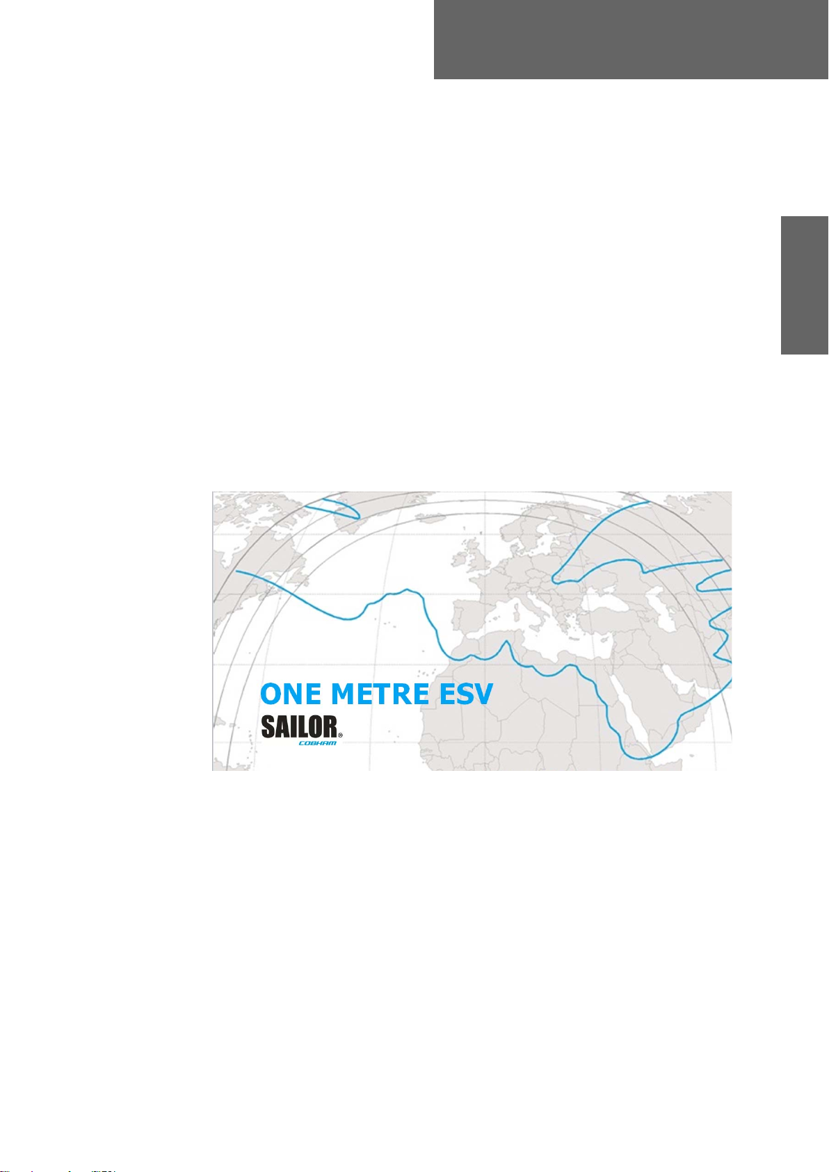
The SAILOR 600 VSAT Ka is a unique stabilized maritime VSAT antenna system operating in
the Ka-band (26.5 to 40 GHz). It provides bi-directional IP data connections both on
regional satellite beams and quasi-global Ka-band satellite networks. The following figure
shows a coverage map of the Ka service.
Figure 2-1: Coverage map for a Ka service (example)
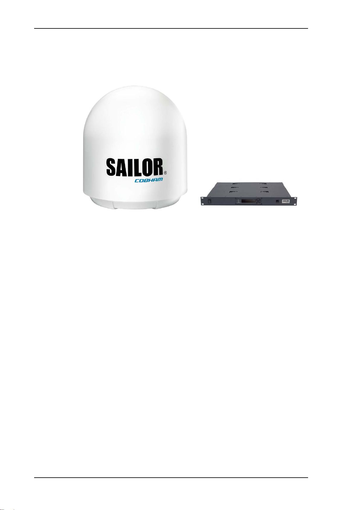
The SAILOR 600 VSAT Ka system consists of the following units:
• SAILOR 7006B Above Deck Unit (ADU)
• SAILOR 7016B Antenna Control Unit (ACU)
• SAILOR 6080 AC/DC Power Supply Unit (optional)
The system requires a single 50 Ohm cable to provide the Above Deck Unit (ADU) with both
DC power, data and control information. The radome does not have to be removed neither
before nor after the installation. To protect the ADU the built-in motors act as brakes during
transport and when the ADU is not powered. You can access the SAILOR 600 VSAT Ka
remotely and make in-depth performance analysis using the built-in web interface.
98-148248-A 2-1
SAILOR 600 VSAT Ka system
Above Deck
Unit (ADU)
Antenna Control Unit (ACU)
The following figure shows the SAILOR 600 VSAT Ka system.
SAILOR 600 VSAT Ka features
Single 50 Ohm coax cable for the ADU.
One-Touch Commissioning.
Gyro-free operation.
SNMP support.
Secure connection, HTTPS and SSH.
Remote access using SAILOR FleetBroadband over WAN.
Remote or local simultaneous software update of ADU and ACUvia PC and Internet
browser.
Full remote control and troubleshooting with built-in test equipment (BITE).
ACU with 4 x LAN, NMEA 0183, RS-232 and RS-422.
No scheduled maintenance.
Figure 2-2: ADU and ACU
2-2 Chapter 2: Introduction 98-148248-A
Introduction
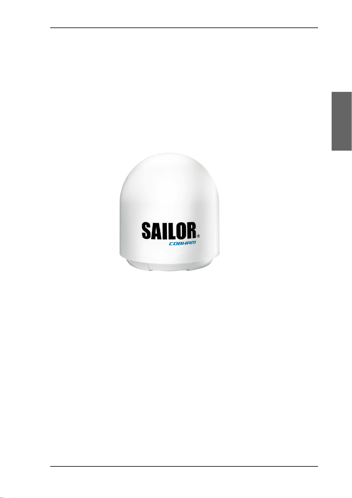
2.1.2 Above Deck Unit (ADU)
The SAILOR 600 VSAT Ka ADU is a 65 cm stabilized tracking antenna, consisting of a
suspended antenna with a standard global RF configuration. It is stabilized by heavy duty
vibration dampers in 3-axis and can be used in environments with elevations of -28° to +
120°. The ADU weighs 37 kg and is powered by the ACU. The ADU is protected by a
radome.
All communication between the ADU and the ACU passes through a single standard
50 Ohm cable (with N connector) through the rotary joint. No cable work is required inside
the radome.
SAILOR 600 VSAT Ka system
Figure 2-3: Above Deck Unit (ADU)
98-148248-A Chapter 2: Introduction 2-3
SAILOR 600 VSAT Ka system
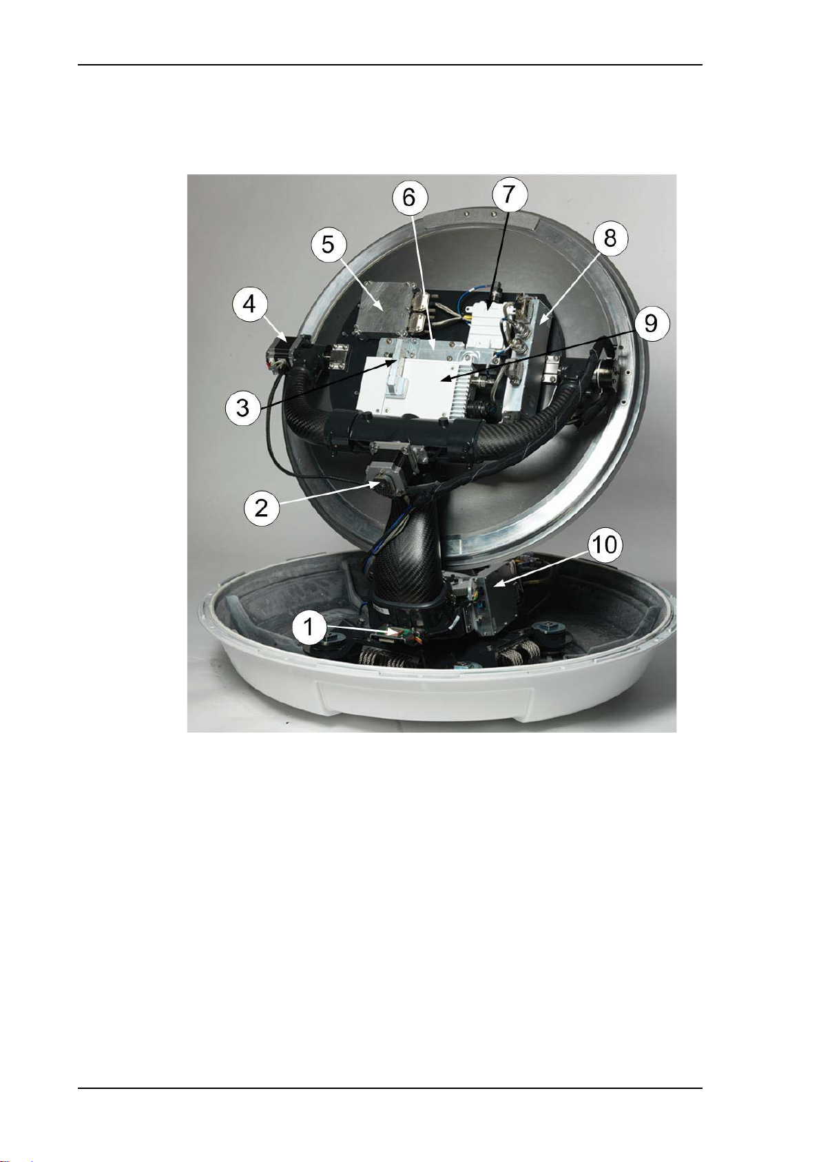
Modules in the SAILOR 600 VSAT Ka ADU
Figure 2-4: Above Deck Unit modules 1/2
1. GNSS module.
2. X-elevation motor and encoder.
3. Wave guide.
4. Elevation motor and encoder
5. Inertial Sensor Module (ISM2).
6. Polariser.
7. Low Noise Block downconverter (LNB),
8. BUC Control Module (BCM).
9. Block Up Converter (BUC).
10. Pedestal Control Module (PCM2).
2-4 Chapter 2: Introduction 98-148248-A
SAILOR 600 VSAT Ka system
Introduction
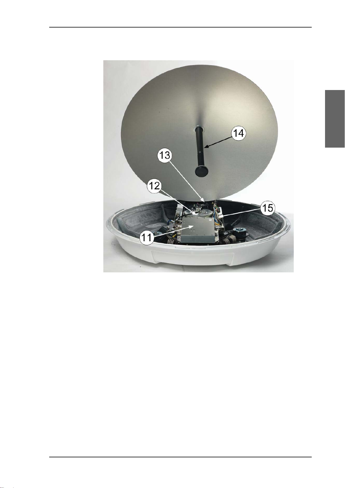
Figure 2-5: Above Deck Unit modules 2/2
11. VSAT Interface Module (VIM2).
12. Azimuth motor and encoder.
13. Zero Reference Module (ZRM)
14. Feed horn.
15. Field Vector Driver Module (FDM).
A lifting harness (included in the delivery helps getting the ADU safely into place. Satellite
profile parameters are entered in the built-in web server of the ACU, using a PC. The system
configuration is saved in two modules, there is no loss of data at repair.All modules have a
service and power LED status indicator. Each module is encapsulated in a metal box with
self-contained mounting bolts. If necessary, belts and modules can be exchanged on site.
The ADU software is updated automatically when you make a software update of the ACU.
98-148248-A Chapter 2: Introduction 2-5
SAILOR 600 VSAT Ka system
/$1WRIURQW
7[,Q5[2XW*URXQG
/$1
56
10($
'&3RZHU
56
$QWHQQD
$&8
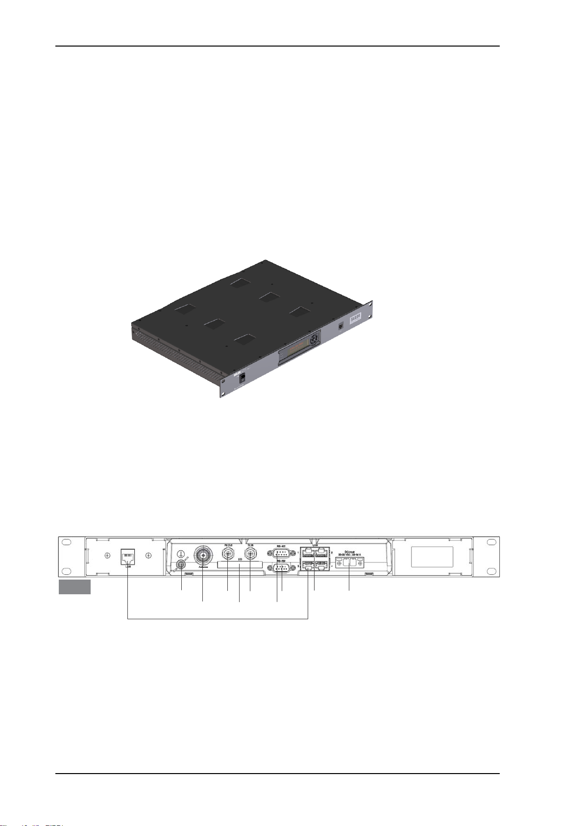
2.1.3 Antenna Control Unit (ACU)
The ACU is the central control unit in the system. It contains all user interfaces and
manages all communication between the ADU and the connected modem, a connected PC
and an optional FleetBroadband service communication line. The ACU has a display, status
LEDs and a keypad. It provides a DHCP client. During configuration you can configure
heading offset, save satellite setups and enter No Transmit Zones (blocking zones in which
the ADU does not transmit).
The user PC (user WAN) for Internet access etc. is connected to the ACU, not the modem.
The ACU provides DC power to the ADU through a single coaxial cable. You can use the
SAILOR 6080 AC/DC Power Supply to provide the DC power to the ACU. The ACU comes in
a 19” rack version.
Figure 2-6: Antenna Control Unit
You can do remote diagnostics and service with the ACU. Its built-in test equipment
constantly checks the device for proper functioning. It performs POST (Power On Self Test)
and you can request a PAST (Person Activated Self Test). Continuous Monitoring (CM) is
also available. BITE error codes can be read out in the web interface and in the display of
the ACU.
You can make a software update with a connected PC and the built-in web interface of the
ACU. The ACU has the following interfaces and switch:
Figure 2-7: ACU (connector panel)
• N-connector for ADU cable (50 Ohm).
• 2 x F connectors for Rx and Tx cables (75 Ohm) to modem.
• Multi connector for NMEA interfaces (for input from GPS compass or Gyro compass).
• RS-422 interface for BUC I/O.
2-6 Chapter 2: Introduction 98-148248-A
Introduction
• RS-232 interface for modem control.
&RQWURO
YLD$&8
7[2XW
5[,Q*URXQG
56
&RQVROH
$&3RZHU
5[,Q
QRWDFWLYH
56
%8&,2
• 4 x LAN ports for modem control and user equipment.
• Ground wing nut
• Power connector.
• On/Off power switch (at the front).
The ACU also has a LAN connector at the front to access the service port from the ACU
front panel.
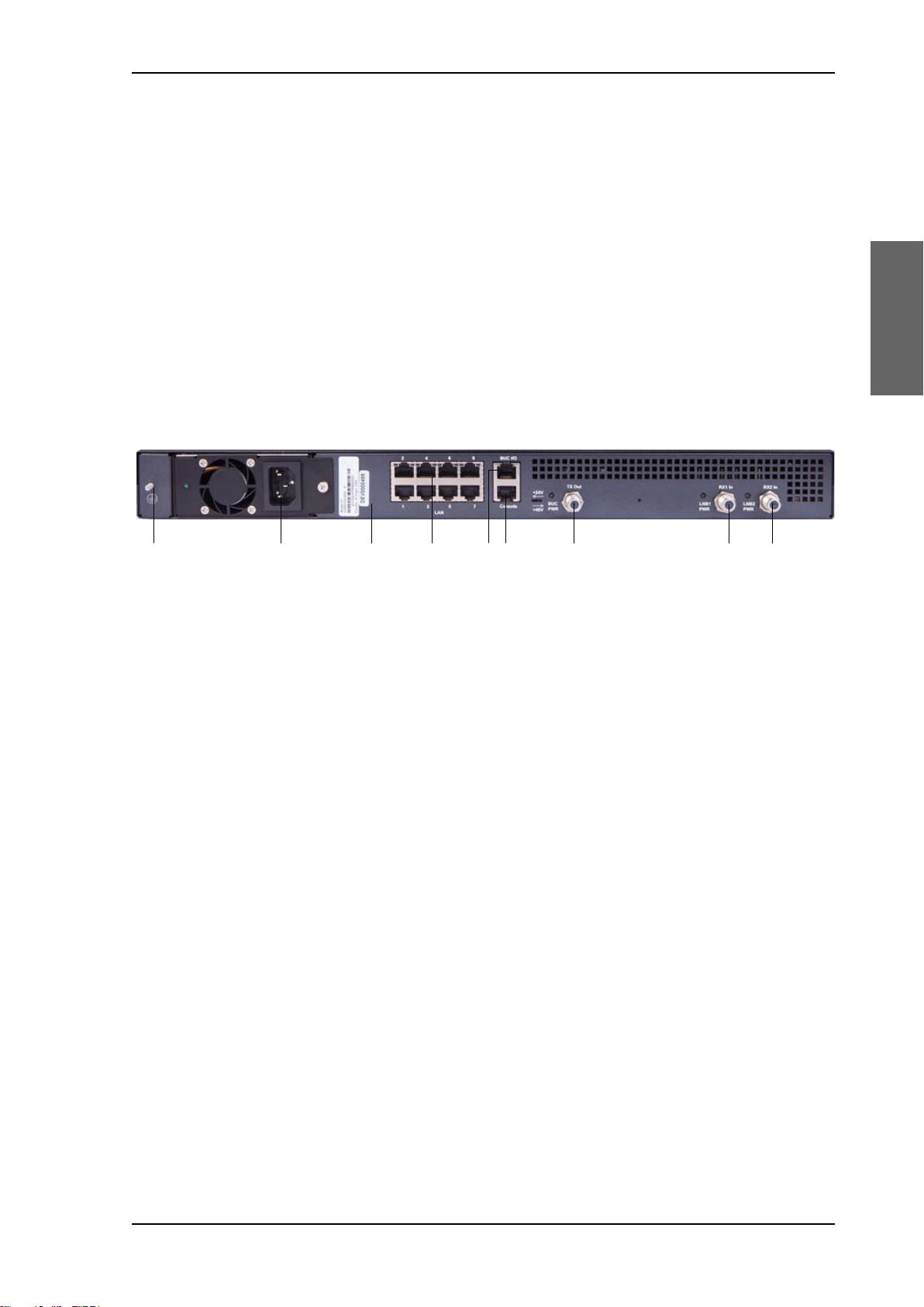
2.1.4 iDirect X7 Modem
The iDirect X7 Modem is the modem in the system. The modem is not supplied by Cobham
SATCOM. The modem has the following interfaces and connectors:
SAILOR 600 VSAT Ka system
Figure 2-8: Connector panel of the iDirect X7 modem
•GND
• 100-240 VAC power connector
• 8 LAN ports, one to ACU
• RS-422 interface BUC I/O
• RS-232 Console for modem control
• Tx Out (F-connector)
• RX1 and RX2 (RX 2 not used) (F connector)
2.1.5 Satellite type approvals
For a list of satellite type approvals see Appendix E, Approvals.
2.1.6 Service activation
Before you can start using the SAILOR 600 VSAT Ka, you need to activate the system for
the Ka service. Contact your service provider for activation.
98-148248-A Chapter 2: Introduction 2-7
Part numbers and options
2.2 Part numbers and options
2.2.1 Applicable model and part numbers
The following model and part numbers are available for the SAILOR 600 VSAT Ka system:
Part number Description
407006B-00500 Above Deck Unit (ADU)
407016B-00530 Antenna Control Unit (ACU)
Table 2-1: Part numbers for the SAILOR 600 VSAT Ka system
2.2.2 Options for SAILOR 600 VSAT Ka
The following options are available for the SAILOR 600 VSAT Ka system:
Part number Description
406080A-00500 SAILOR 6080 AC/DC Power Supply
407090A-950 Antenna cable 50 m N-Conn (not mounted), male/male
407090A-925 Pigtail Cable 1.25 m, N-Conn, female/male
406080A-005 19” Rack mount kit for SAILOR 6080 AC/DC Power Supply
Table 2-2: Part numbers for options of the SAILOR 600 VSAT Ka system
2-8 Chapter 2: Introduction 98-148248-A

Chapter 3
Installation
Installation 3
This chapter has the following sections:
• What’s in the box
• Site preparation
• Installation of the ADU
• Installation of the ACU
• Installation of the modem
• To connect the ADU, ACU and modem
3.1 What’s in the box
3.1.1 To unpack
Unpack the ADUand ACU. Check that the following items are present:
• SAILOR 7006B ADU
• Accessory kit for SAILOR 7006B ADU:
• Package with bolts and washers
•Lifting harness
• SAILOR 7016B ACU
• Accessory kit for SAILOR 7016B ACU:
• NMEA multi-connector
• Connector 2PF pi7.62 straight
• RJ45 patch cable (0.5 m)
• Coax cable F-F, low loss, 75 Ohm (2 pcs)
•RJ45 patch cable (2m)
• X7 Modem BUC & Console to ACU cable
• Installation manual
98-148248-A 3-1
What’s in the box
3.1.2 Initial inspection
Inspect the shipping cartons immediately upon receipt for evidence of damage during
transport. If the shipping material is severely damaged or water stained, request that the
carrier's agent be present when opening the cartons. Save all box packing material for future
use.
WARNING! To avoid electric shock, do not apply
power to the system if there is any sign of shipping
damage to any part of the front or rear panel or the outer
cover. Read the safety summary at the front of this
manual before installing or operating the system.
After unpacking the system, i.e. opening the cartons, inspect it thoroughly for hidden
damage and loose components or fittings. If the contents are incomplete, if there is
mechanical damage or defect, or if the system does not work properly, notify your dealer.
3.1.3 Tools needed
• Torque wrench to fasten the mounting bolts for the ADU
• Torque wrench to fasten the N connector at the ADU
• PC and Internet browser
•Crimping tools
3.1.4 Transport of the antenna
During transport the antenna must be able to move freely inside the radome. You must
follow the instructions below to keep a valid warranty:
CAUTION!
Do not strap parts of the antenna.
This might cause damage to the antenna.
Damage due to actions listed above will void the warranty.
3-2 Chapter 3: Installation 98-148248-A

Installation
3.2 Site preparation
Important
The following topics have to be considered when installing the ADU:
• General site considerations
• Obstructions (ADU shadowing)
• Blocking zones with azimuth and elevation
• Safe access to the ADU (radiation hazard)
• Ship motion and offset from the ship’s motion centre
• Mast foundation and height
• Interference from radar, GPS and other transmitters
• Condensation, water intrusion and deposits
3.2.1 General site considerations
For optimum system performance, you must follow some guidelines on where to install or
mount the different components of the SAILOR 600 VSAT Ka System.
Site preparation
1. Mount the ADU on stiffened structures with a minimum of exposure to vibrations.
You do not have to align the ADU with the bow-to-stern line of the ship. When configuring
the SAILOR 600 VSAT Ka system, the azimuth calibration provides the correct azimuth of
the ADU.
Painting the radome
Customers may wish to paint the radome in order to match the vessel’s colour. Cobham
SATCOM’s recommendation is that the radome should NOT be painted because it may
impact RF performance and may lead to over-heating, causing the antenna to go in safe
mode (switch off).
However, painting the radome will not void the general warranty regarding material and
workmanship etc. It is only the performance that cannot be guaranteed. Any paint used
must be non-metallic based.
It is recommended to mount the ADU in a location with as much 360° free
line of sight to the satellite as possible while making sure that the support
structure fulfills the requirements for the mast foundation.
98-148248-A Chapter 3: Installation 3-3
Site preparation
Note
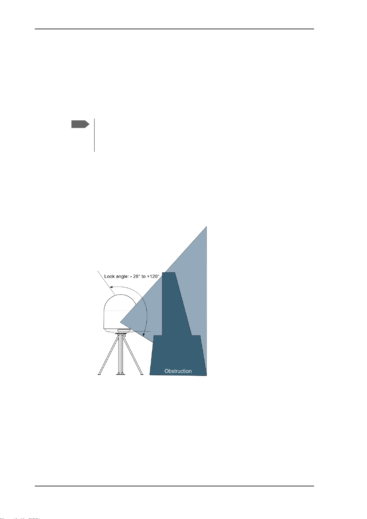
3.2.2 Obstructions (ADU shadowing)
The ADU is stabilized in 3-axis (plus skew) and can be used in environments with elevations
of -28° to + 120° to allow for continuous pointing even in heavy sea conditions. The ADU
beam is approximately m in diameter for the first 30 m from the ADU. Beyond 30 m the
beam gradually widens so that it is approximately 5 m in diameter at 100 m distance. This
beam expansion continues with increasing distance. Any obstructions, such as masts,
funnels, bridge house etc. within this field can cause signal degradation or signal loss.
Note that due to the short wavelength at Ka band and the
narrow beam width of the ADU even a 6 mm steel wire
placed within 50 m inside the beam can causes signal
degradation.
For optimum performance adhere to the following guidelines:
1. Place the ADU so that it has as much free line-of-sight as possible without any
structures in the beam through one full 360 degrees turn of the vessel.
2. Do not place the ADU close to large objects that may block the signal.
3. Elevate the ADU by mounting it on a mast or on a mounting pedestal on a deck or deck
house top to avoid obstruction.
Figure 3-1: Signal degradation because of obstructing objects
3-4 Chapter 3: Installation 98-148248-A
Installation
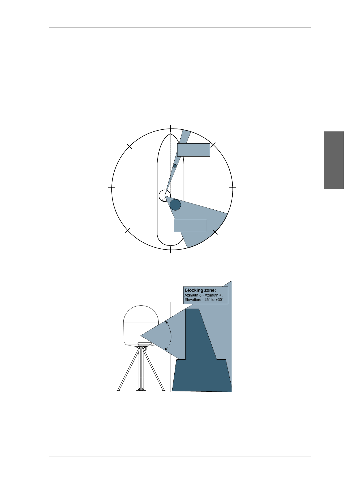
3.2.3 Blocking zones with azimuth and elevation
$QWHQQD
2EVWUXF
WLRQ
$]LPXWK
$]LPXWK
$]LPXWK
$]LPXWK
%ORFNLQJ]RQH
$]LPXWK$]LPXWK
(OHYDWLRQWR
%ORFNLQJ]RQH
$]LPXWK$]LPXWK
(OHYDWLRQWR
Your installation may require that you set up blocking zones for the ADU, i.e. areas where
the ADU will not transmit and areas where transmit power is potentially dangerous for
persons frequently being in these zones. You can set up 8 blocking zones. Each blocking
zone is set up with azimuth start and stop, and elevation angle. The blocking zones are set
up in the built-in web interface of the ACU during configuration. For further information see
To set up blocking zones (RX and TX) on page 6-22.
Site preparation
Figure 3-2: 2 blocking zones with no-transmit zones, azimuth (example)
Figure 3-3: Blocking zone with no-transmit zones, elevation angle (example)
98-148248-A Chapter 3: Installation 3-5
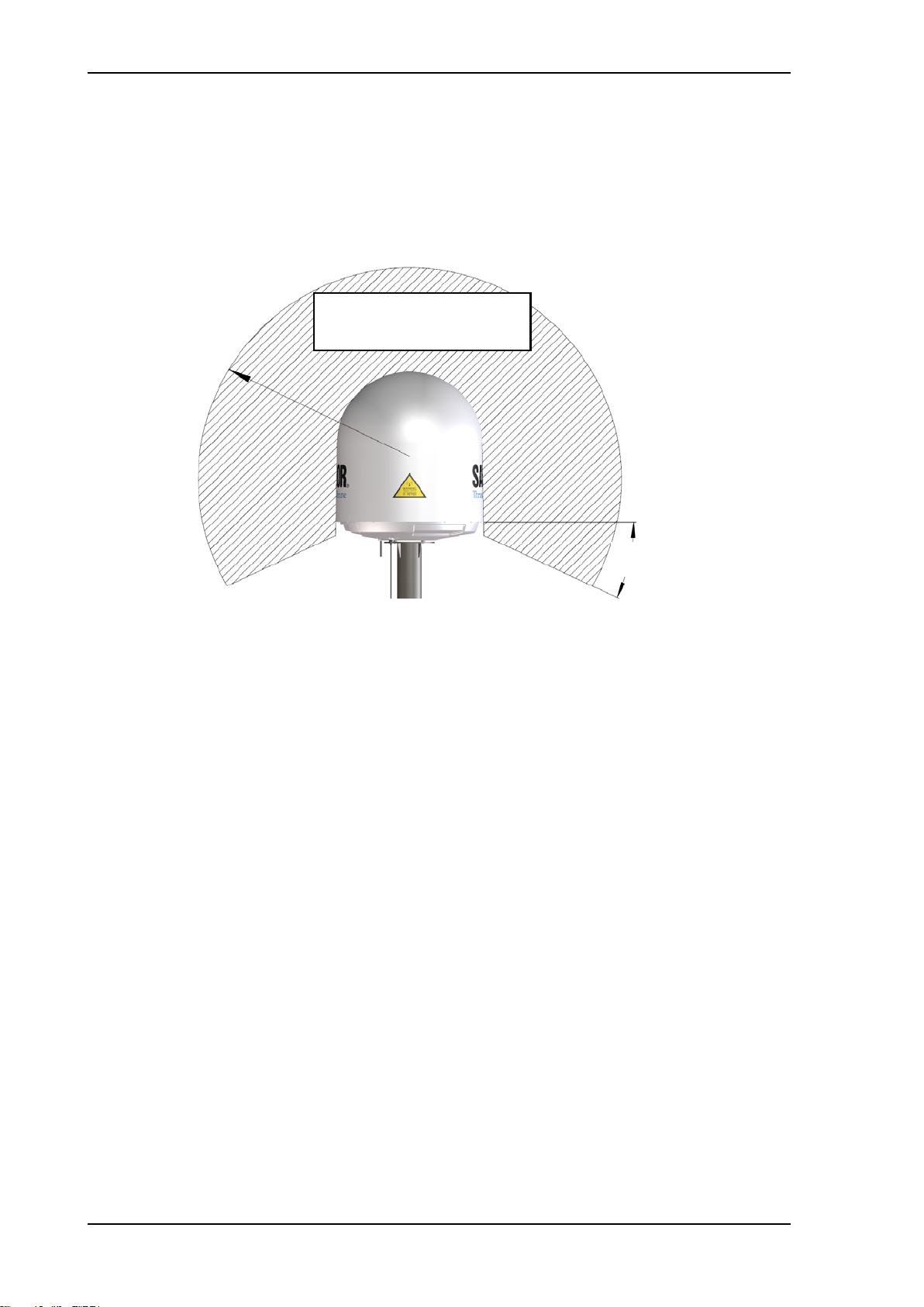
Site preparation
MICROWAVE RADIATION
NO PERSONNEL within safety
distance of 30 m, based on 10 W/m
2
28°
3.2.4 Safe access to the ADU (radiation hazard)
The ADU radiates up to 50.4 dBW EIRP at 29.5 GHz. This translates to a minimum safety
distance of 30 m from the ADU while it is transmitting, based on a radiation level of
10 W/m
2
.
Figure 3-4: Radiation hazard, safety distance 30 m
3-6 Chapter 3: Installation 98-148248-A
 Loading...