

Page 1

The most important thing we build is trust
OMU I
Optical Master Unit Mark I
User Manual – A1829300UM Rev. 3.1
THIS DOCUMENT IS VALID FOR ALL OMU MARK I MODELS
Page 2

OPTICAL MASTER UNIT MARK I
PRODUCT DESCRIPTION AND USER’S MANUAL
Cobham Wireless – Coverage Date: 4-Jan-18 www.cobham.com/wireless
Document number:A1829300UM Rev. 3.1
Page | II
Copyright © 2018 Axell Wireless Limited tra ding as Cobham Wireless
All rights reserved.
No part of this document may be copied, distributed, transmitted, transcribed, stored in a retrieval system, or
translated into any human or computer language without the prior written permission of Axell Wireless Limited
trading as Cobham Wireless.
The manufacturer has made every effort to ensure that the instructions contained in this document are
adequate and free of errors and omissions. The manufacturer will, if necessary, explain issues which may not be
covered by this document. The manufacturer's liability for any errors in the document is limited to the correction
of errors and the aforementioned advisory services.
This document has been prepared to be used by professional and properly trained personnel, and the customer
assumes full responsibility when using them. The manufacture r we lcomes customer comments as part of the
process of continual development and improvement of the documentation in the best way possible from the
user's viewpoint. Please submit your comments to the nearest Cobham Wireless sales representative.
Contact Information
Headquarters Axell Wireless trading as Cobham Wireless
Aerial House, Asheridge Road
Chesham, Buckinghamshire
HP5 2QD, United Kingdom
Tel: +44 1494 777000
Fax: +44 1494 777002
Commercial inquiries
cw.coverage@cobham.com
Website
www.cobham.com/wireless
Support issues
cw.support@cobham.com
Technical Support Line, English speaking +44 1494 777 747
About This Manual
This Product Manual provides the following information:
• Description of the unit
• Procedures for setup, configuration and checking the proper operation of the unit
• Maintenance and troubleshooting procedures
For whom it is intended
This Product Manual is intended for experienced technicians and engineers. It is assumed that the customers
installing, operating, and maintaining Cobham Wireless Repeaters are familiar with the basic functionality of
Repeaters.
Notice
Confidential - Authorized Customer Use
This document may be used in its complete form only and is solely for the use of Cobham Wireless em plo yees
and authorized Cobham Wireless channels or customers. The material herein is proprietary to Cobham Wireless.
Any unauthorized reproduction, use or disclosure of any part thereof is strictly prohibited.
All trademarks and registered trademarks are the property of their respective owners.
Page 3

OPTICAL MASTER UNIT MARK I
PRODUCT DESCRIPTION AND USER’S MANUAL
Cobham Wireless – Coverage Date: 4-Jan-18 www.cobham.com/wireless
Document number:A1829300UM Rev. 3.1
Page | III
Disclaimer of Liability
Contents herein are current as of the date of publication. Cobham Wireless reserves the right to change the
contents without prior notice. The information furnished by Cobham Wireless in this document is believed to be
accurate and reliable. However, Cobham Wireless assumes no responsibility for its use. In no event shall
Cobham Wireless be liable for any damage resulting from loss of data, loss of use, or loss of profits and Cobham
Wireless further disclaims any and all liability for indirect, incidental, special, consequential or other similes
damages. This disclaimer of liability applies to all products, publications and services during and after the
warranty period.
Safety Instructions and Warnings
Throughout this manual, important safety warnings and admonishments are included to warn of possible
hazards to persons or equipment. A safety warning identifies a possible hazard and then describes what may
happen if the hazard is not avoided. The safety warnings – in the form of Dangers, Warnings and Cautions must
be followed at all times. These warnings are flagged by the use of a warning icon, usually the triangular alert
icon seen below. The exclamation point within the triangular alert icon is intended to warn the operator or
service personnel of operation and maintenance from factors relating to the product and its operating
environment, which could pose a safety hazard.
General Safety Warnings Concerning Use of T his Syst em
Always observe standard safety precautions during installation, operation and maintenance of this product.
System Maintenance
• In the event of a failure Cobham Wireless’s support service should be contacted for advice on a possible
module replacement or other action to be taken.
• If a shipment of a unit back to Cobham Wireless is made within the period of guarantee the original packing
must be used.
• The system normally operates without any operator intervention or maintenance. If in the unlikely event of
any unit failure, the faulty repeater should be replaced. A failed unit can be removed and replaced with a
spare while the rest of the system (other repeaters) is still operating. However, the power supply of the
failed repeater should be isolated from the power before anything is replaced.
• Component Replacement - None of the modules in the repeater can be replaced without removing the
repeater from its mounting and opening the cover of the repeater.
Product Disposal
CAUTION!! Product Disposal - Disposal of this product must be handled according to all national
laws and regulations. For detailed information regarding materials, please refer to Cobham
Wireless.
Page 4

OPTICAL MASTER UNIT MARK I
PRODUCT DESCRIPTION AND USER’S MANUAL
Cobham Wireless – Coverage Date: 4-Jan-18 www.cobham.com/wireless
Document number:A1829300UM Rev. 3.1
Page | IV
General Safety Warnings Concerning Use of Syst em
Caution labels!
Throughout this manual, there are "Caution" warnings. "Caution" calls attention to a
procedure or practice, which, if ignored, may result in injury or damage to the system,
system component or even the user. Do not perform any procedure preceded by a
"Caution" until the described conditions are fully understood and met.
Danger:
Electrical Shock
To prevent electrical shock when installing or modifying the system power wiring,
disconnect the wiring at the power source before working with un insulated wires or
terminals.
Caution: Safety
to personnel
o Before installing or replacing any of the equipment, the entire manual should be
read and understood.
o The user needs to supply the appropriate AC or DC power to the repeater.
Incorrect power settings can damage the repeater and may cause injury to the
user.
o Please be aware that the equipment may, during certain conditions become very
warm and can cause minor injuries if handled without any protection, such as
gloves.
Caution: Safety
to equipment
o When installing, replacing or using this product, observe all safety precautions
during handling and operation. Failure to comply with the following general safety
precautions and with specific precautions described elsewhere in this manual
violates the safety standards of the design, manufacture, and intended use of this
product.
o Changes or modifications not expressly approved by the party responsible for
compliance could void the user’s authority to operate the equipment.
o Cobham W ir eless assumes no liabi lity for the customer's failure to comply with
these precautions. This entire manual should be read and understood before
operating or maintaining the repeater.
Warning:
Restricted
Access Location
Access to the unit installation location is restricted to SERVICE PERSONNEL who have
been instructed on the restrictions and the required precautions to be taken.
Attention:
Electrostatic
Sensitivity
o Observe electrostatic precautionary procedures.
o ESD = Electrostatic Discharge Sensitive Device.
o Static electricity can be conducted to the semiconductor chip from the centre pin of
the RF input connector, and through the AC connector pins. When unpacking and
otherwise handling the repeater, follow ESD precautionary procedures including
use of grounded wrist straps, grounded workbench surfaces, and grounded floor
mats.
Caution: Class 1
Laser
The repeaters described in this manual are equipped with class 1 lasers which have
been tested to meet IEC / EN 60825-1:2014 standards.
CAUTION! - Un-terminated optical receptacles may emit laser radiation. Exercise
caution as follows:
o Use of controls or adjustments or performances of procedures other than those
specified herein may result in hazardous radiation exposure.
o Do not stare into beam or view with optical instruments. Optical transmitters in the
fiber optic converter can send out high energy invisible laser radiation. There is a
risk for permanent damage to the eye.
o Always use protective cover on all cables and connectors which are not connected.
o Never look directly into a fiber cable or a connector.
o Consider that a fiber can carry transmission in both directions.
o During handling of laser cables or connections, ensure that the source is switched
off.
o Regard all open connectors with respect and direct them in a safe direction and
never towards a reflecting surface. Reflected laser radiation should be regarded as
equally hazardous as direct radiation.
Page 5

OPTICAL MASTER UNIT MARK I
PRODUCT DESCRIPTION AND USER’S MANUAL
Cobham Wireless – Coverage Date: 4-Jan-18 www.cobham.com/wireless
Document number: A1829300UM Rev. 3.1
Page | V
Table of Conten ts
1 Introduction .................................................................................................................................... 1
1.1 Features .................................................................................................................................. 2
1.2 Models and Ordering Information ............................................................................................ 2
1.3 OMU Installation Configurations .............................................................................................. 3
1.3.1 Single OMU Topology ............................................................................................... 3
1.3.2 Cascading OMUs ...................................................................................................... 4
1.3.3 Expansion using Multi-color Laser System ............................................................... 4
1.4 OMU Modules .......................................................................................................................... 5
1.4.1 WDM Fibre Optic Converter ...................................................................................... 6
1.4.2 UL Combiner and DL Splitter .................................................................................... 6
1.4.3 6-Way UL/DL RF Simplex Interface Cards ............................................................... 7
1.4.4 Control Module .......................................................................................................... 7
1.4.5 External Alarm and Battery Module........................................................................... 8
1.4.6 Modem Unit ............................................................................................................... 8
1.4.7 Modem Antenna ........................................................................................................ 9
1.4.8 Rack Communication Board ...................................................................................... 9
1.4.9 Power Supplies.......................................................................................................... 9
1.5 Rear Panel ............................................................................................................................. 10
2 Installation .................................................................................................................................... 11
2.1 Unpacking ............................................................................................................................. 11
2.2 Mounting in Rack .................................................................................................................. 11
2.3 Grounding ............................................................................................................................. 11
2.4 Connections .......................................................................................................................... 12
2.4.1 Single Sector RF Connections ................................................................................ 12
2.4.2 Configuration at Delivery is Alternative 1. ............................................................... 13
2.4.3 Fibre Optic Connections .......................................................................................... 13
2.4.4 Connections for Cascaded OMU Units ................................................................... 14
2.4.5 External Alarm and Relay Connections .................................................................. 15
2.4.6 Modem Connections ............................................................................................... 16
2.5 Connecting Power and Power-up .......................................................................................... 17
2.6 OMU Module Configuration Examples ................................................................................... 18
3 Setup ............................................................................................................................................ 20
3.1 Initiate Local Communication ................................................................................................ 20
3.1.1 RMC Communication .............................................................................................. 20
3.2 Configure the OMU ................................................................................................................ 21
3.2.1 Set OMU Name (TAG) ............................................................................................ 21
3.3 Fiber Loss Compensation and Master Attenuation ................................................................ 21
3.4 External Alarms ..................................................................................................................... 22
3.5 Relay ..................................................................................................................................... 23
3.6 Integration into AEM .............................................................................................................. 23
3.7 Set Up OMU-Repeater System ............................................................................................... 24
3.8 Balance the System ............................................................................................................... 25
3.8.1 Downlink Path.......................................................................................................... 25
3.8.2 Fiber Loss Compensation ....................................................................................... 26
3.8.3 Uplink Path .............................................................................................................. 27
3.8.4 Noise Considerations .............................................................................................. 27
3.9 Initiate Fibre Loss Compensation .......................................................................................... 27
3.10 Set up Remote Communication ............................................................................................. 30
Page 6

OPTICAL MASTER UNIT MARK I
PRODUCT DESCRIPTION AND USER’S MANUAL
Cobham Wireless – Coverage Date: 4-Jan-18 www.cobham.com/wireless
Document number:A1829300UM Rev. 3.1
Page | VI
3.10.1 Communication via Modem ..................................................................................... 30
3.10.2 Communication via Wireless Modem ...................................................................... 31
3.10.3 Communication via PSTN (Fixed) Modem .............................................................. 34
3.10.4 Communication via TCP/IP and Ethernet................................................................ 35
3.10.5 Troubleshooting Remote Communication ............................................................... 35
3.11 Integrate into the AEM ........................................................................................................... 41
3.12 Installation Examples ............................................................................................................ 41
3.12.1 OMU Signal Tapped at BTS .................................................................................... 41
3.12.2 OMU Signal Source provided by Repeater ............................................................. 42
3.12.3 Multi-Sector Configurations - Up to Six Sectors ...................................................... 43
3.12.4 Changing UL Combiner and DL Splitter Connections ............................................. 44
4 Troubleshooting............................................................................................................................ 45
4.1 Module LEDs ......................................................................................................................... 45
4.1.1 WDM Module LEDs ................................................................................................. 45
4.1.2 Control Module LEDs .............................................................................................. 46
4.1.3 GSM Modem Behaviour .......................................................................................... 47
5 Maintenance.................................................................................................................................. 48
5.1 General ................................................................................................................................. 48
5.2 Preventive Maintenance ........................................................................................................ 48
5.3 Product Disposal ................................................................................................................... 48
Appendix A: Specifications ................................................................................................................... 49
Appendix B: F/O Cleaning Procedure .................................................................................................... 50
Appendix C: EU Declaration of Conformity ........................................................................................... 54
Page 7

OPTICAL MASTER UNIT MARK I
PRODUCT DESCRIPTION AND USER’S MANUAL
Cobham Wireless – Coverage Date: 4-Jan-18 www.cobham.com/wireless
Document number: A1829300UM Rev. 3.1
Page | 1
1 INTRODUCTION
The Cobham Wirele ss OMU is a scalable , RF to opt ic signal c onversion u nit. The unit is installed near
the Base Station and is us ed in combinat ion with fibre fed repeaters to provide wireless coverage for
remote sites located at a distance of up to 20 km (12.42 miles) from the Base Station.
The OMU taps the signal directly off a base station via a coupler and performs the RF to optic
conversion of the base station signal for transmission to the fibre connected repeaters. (In the
uplink, the procedure is reversed).
The OMU can either be installed at the BS or co nnecte d directly to a re peat er. In tha t case the signa l
is tapped from the repeater’s service antenna.
An OMU can be equipped to be used for frequency ranges from 88 MHz to 2170 MHz.
A single OMU unit supports up to 6 fibre o ptic converters, where each converter provides the signal
conversion for one Repeater. The system can be expanded to support up to 24 Repeaters.
The figure below illustrates an OMU system with six F/O converters and two power supplies.
Figure 1-1. Example of OMU System
ERR
PWR
UL
DATA
DL
DATA
IN
OUT 1
OUT 2
ERR
PWR
UL
DATA
DL
DATA
IN
OUT 1
OUT 2
RF in
DL out
UL in
RF out
Modem Status
Modem Power
Status
Login
.
.
.
.
.
.
.
.
.
.
.
.
.
.
.
.
.
.
LMT Port
Ethernet
Modem
ANT
PWRPWR
In OK
Out OK
In OK
Out OK
ERR
PWR
UL
DATA
DL
DATA
OPTO
Rx
OPTO
Tx
SC/APC
ERR
PWR
UL
DATA
DL
DATA
OPTO
Rx
OPTO
Tx
SC/APC
ERR
PWR
UL
DATA
DL
DATA
OPTO
Rx
OPTO
Tx
SC/APC
ERR
PWR
UL
DATA
DL
DATA
OPTO
Rx
OPTO
Tx
SC/APC
ERR
PWR
UL
DATA
DL
DATA
OPTO
Rx
OPTO
Tx
SC/APC
ERR
PWR
UL
DATA
DL
DATA
OPTO
Rx
OPTO
Tx
SC/APC
ERR
PWR
UL
DATA
DL
DATA
OPTO
Rx
OPTO
Tx
SC/APC
ERR
PWR
UL
DATA
DL
DATA
OPTO
Rx
OPTO
Tx
SC/APC
ERR
PWR
UL
DATA
DL
DATA
OPTO
Rx
OPTO
Tx
SC/APC
ERR
PWR
UL
DATA
DL
DATA
OPTO
Rx
OPTO
Tx
SC/APC
ERR
PWR
UL
DATA
DL
DATA
OPTO
Rx
OPTO
Tx
SC/APC
ERR
PWR
UL
DATA
DL
DATA
OPTO
Rx
OPTO
Tx
SC/APC
PWR
Battery
Power
LinkOK
On
Off
On
Off
On
Off
Page 8

OPTICAL MASTER UNIT MARK I
PRODUCT DESCRIPTION AND USER’S MANUAL
Cobham Wireless – Coverage Date: 4-Jan-18 www.cobham.com/wireless
Document number:A1829300UM Rev. 3.1
Page | 2
1.1 Features
• Frequency ranges from 88 MHz to 2 170 MHz.
• WDM technology (Wavelength Division M ultiplexing) – single fibre connection to each Repeater
• Each OMU supports up to 6 Repeaters
• Scalability – up to four OMUs can be cascaded for support of up to 24 Repeaters
• Multi-sectors support - OMU I can support up to six sectors (model specific)
• Single-source management – cascaded OMUs can be controlled via the “Master” OMU
• Two independent power supplies (in the unit) – can be us ed to either:
• all ow for flexibility in power supply source selectio n according to the type of voltage available
on site: 115 – 230 VAC 50/60 Hz and 24 – 48 VDC
• provide power supply redundancy by installing two power supplies of the same type
• Flexible RF signal source – RF signal can be acquired either from the BS or from the Repeater's
Service antenna
• Easily replaceable modules
• Simple, local setup via RS232 connection
• Remote management via Ethernet connection or via modem
• Various types of modems are supported: for example GSM, GSM-R, HSDPA/UMTS, TETRA, GPRS
and PSTN.
• Single modem (installed at the Master OMU) is required for management of cascaded OMUs
• Modem can be integrated (part of the Control module) or connected separately
1.2 Models and Ordering Information
OMU is available in a range of models corresponding to repeater products
Page 9

OPTICAL MASTER UNIT MARK I
PRODUCT DESCRIPTION AND USER’S MANUAL
Cobham Wireless – Coverage Date: 4-Jan-18 www.cobham.com/wireless
Document number:A1829300UM Rev. 3.1
Page | 3
1.3 OMU Installation Configurations
The OMU can be installed in several configurations:
• Basic configuration of a single OMU installed at the BTS
• Expanding the system by either:
• Linking several OMUs (up to four)
• Using la ser systems with three or four colours.
1.3.1 Single OMU Topolog y
The following figure illustrates the connections for a single OMU installed at the BTS. The OMU
supports up to six Repeaters, where each repeater is connected via optic fibre to an RF/Optic
converter module on the OMU. Each OMU supports up to six RF/Optic converters – for connections to
up to six Repeaters.
In the downlink the radio signal is tapped from a BTS using a coupler installed in series with the
BTS’s antenna cable. The Fibre Optic Converter in the OMU converts the RF signal to an optical signal
and sends it to the repeater over a fibre.
In the uplink the Fibre Optic Converter receives the optical RF signal from the repeater, converts it to
electrical RF signal and sends it to the BTS. The signal is transferred to the antenna cable using a
coupler.
Figure 1-2. Example of Single OMU Topology
BTS
Directional
Coupler
RF
OMU
Repeater
Opto Fiber
RF
FiberOptic
Converters
Server
Antenna
Up to Six
Repeaters
Page 10

OPTICAL MASTER UNIT MARK I
PRODUCT DESCRIPTION AND USER’S MANUAL
Cobham Wireless – Coverage Date: 4-Jan-18 www.cobham.com/wireless
Document number:A1829300UM Rev. 3.1
Page | 4
1.3.2 Cascading OMUs
Up to four OMUs can be cascaded and operate up to 24 repeaters as one system: one Master OMU
and three Slave OMUs.
This type of topology requires only one Control module and one modem (at the Master OMU). All
OMUs and hosted Repeaters are managed as a single system via the Master OMU.
Figure 1-3. Four OMUs cascaded in one system
1.3.3 Expansion using Multi-color Laser System
The number of Repeaters supported by each OMU can be expanded using multi-coloured laser
systems.
A laser system with two colours can operate one repeater for each fibre optic converter in an OMURepeater system – one color is used for the uplink and one for the downlink. A laser system with
three or more colours can operate two or more repeaters per fibre optic co nverter. One color is used
for the downlink which is the same for all repeaters, and in the uplink each repeater has its own
color.
The connection from one repeater to the next is done via so called add-drop couplers.
The difference in distance between the repeaters and the OMU can be compensated for
automatically.
Two repeaters are connected to the same converter in the OMU via the same fibre but the
wavelength for the uplink differs betw een the units. Slave 1: 1550 ± 3 nm, Slave 2: 151 0 ± 3 nm.
The downlink signal is the same for both repeaters.
Figure 1-4. Dual-colour Fibre Connections to Two Repeaters
BTS
RepeatersOMU Units
Page 11

OPTICAL MASTER UNIT MARK I
PRODUCT DESCRIPTION AND USER’S MANUAL
Cobham Wireless – Coverage Date: 4-Jan-18 www.cobham.com/wireless
Document number:A1829300UM Rev. 3.1
Page | 5
1.4 OMU Modules
The OMU is a rack type casing designed for a 19” sub-rack. The chassis supports up to six F/O to RF
converters, in addition to C ontrol, Power, Modem and additional required interface units.
Each of the modules is described in detail in the following sections.
Figure 1-5. OMU Front Panel Interfaces
An OMU unit can contain the following modules:
Label Unit Description Allocated Slots
1. Fibre Optic Converter Up to 6 WDM optic convert er s 1, 2, 3 and 6, 7, 8
2. UL Combiner and DL
Splitter
Combine and distribute the RF
signals between the OMU’s RF port
and the Fibre Optic Converters.
4 and 5 respectively
3. Modem Optional. This unit is used for
modems that are not mounted on
the Control Module.
9
4. External Alarm and
Battery Module.
Supports 4 dry-contact alarms, 1
relay, and a battery (can be turned
off) that enables the modem to
transmit am alarm in case of loss of
input power.
10
5. Control Module Relevant only for Master OMU 9 or 11 – without an
integrated wireless
modem (mounted on
the control module).
11 only – if the
module includes a
wireless modem (to
be near modem
antenna module –
slot 14).
6. Rack communication
board
Provides communications link
between the Control Module and the
Fiber Optic Converters.
Also used when cascading OMUs.
12
7. Power Supply modules (A PS B is optional for redundancy 13
ERR
PWR
UL
DATA
DL
DATA
IN
OUT 1
OUT 2
ERR
PWR
UL
DATA
DL
DATA
IN
OUT 1
OUT 2
RF in
DL out
UL in
RF out
Modem Status
Modem Power
Status
Login
.
.
.
.
.
.
.
.
.
.
.
.
.
.
.
.
.
.
LMT Port
Ethernet
Modem
ANT
PWRPWR
In OK
Out OK
In OK
Out OK
ERR
PWR
UL
DATA
DL
DATA
OPTO
Rx
OPTO
Tx
SC/APC
ERR
PWR
UL
DATA
DL
DATA
OPTO
Rx
OPTO
Tx
SC/APC
ERR
PWR
UL
DATA
DL
DATA
OPTO
Rx
OPTO
Tx
SC/APC
ERR
PWR
UL
DATA
DL
DATA
OPTO
Rx
OPTO
Tx
SC/APC
ERR
PWR
UL
DATA
DL
DATA
OPTO
Rx
OPTO
Tx
SC/APC
ERR
PWR
UL
DATA
DL
DATA
OPTO
Rx
OPTO
Tx
SC/APC
ERR
PWR
UL
DATA
DL
DATA
OPTO
Rx
OPTO
Tx
SC/APC
ERR
PWR
UL
DATA
DL
DATA
OPTO
Rx
OPTO
Tx
SC/APC
ERR
PWR
UL
DATA
DL
DATA
OPTO
Rx
OPTO
Tx
SC/APC
ERR
PWR
UL
DATA
DL
DATA
OPTO
Rx
OPTO
Tx
SC/APC
ERR
PWR
UL
DATA
DL
DATA
OPTO
Rx
OPTO
Tx
SC/APC
ERR
PWR
UL
DATA
DL
DATA
OPTO
Rx
OPTO
Tx
SC/APC
PWR
Battery
Power
21 1 543 6 7 8
LinkOK
On
Off
On
Off
On
Off
Page 12

OPTICAL MASTER UNIT MARK I
PRODUCT DESCRIPTION AND USER’S MANUAL
Cobham Wireless – Coverage Date: 4-Jan-18 www.cobham.com/wireless
Document number:A1829300UM Rev. 3.1
Page | 6
Label Unit Description Allocated Slots
and B)
8. Modem Antenna
connections
This module is optional. This is used
for OMUs with wireless modems
installed that need a separate
antenna. This module can also be
equipped with two connectors.
14
1.4.1 WDM Fibre Optic Converter
Caution!
Un-terminated optical receptacles may emit laser radiation.
Do not stare into beam or view with optical instruments.
These modules perform the following functions:
• Provides RF to optical signal conversion in both
directions.
• Downlink and uplink op tical signals are combined
using WDM – only one fibre is required.
• Each WDM Fibre Optic Converter in the OMU works in
parallel with a corresponding unit in t he repeater
which is linked via the fibre (SC/APC port).
• A pilot tone can be sent between the Fiber Optic
Converters in the OMU and the repeater to define the
loss in the fibre. Based on this informat ion the
repeater automatically adjusts the attenuation to
compensate for the fibre loss.
• On the Fibre Optic Converter module there are six
LED indicators; one for power status, one for error,
two for the data communication and two for the RF
signals.
Figure 1-6.WDM Fibre Optic
Converter
1.4.2 UL Combiner and DL Splitter
These modules perform the following functions:
• Combine and distribute the RF signals between the
OMU’s RF port and the Fiber Optic
• Contain attenuators used to set the master signal
levels in the downlink and uplink.
Note: By default, the module ports are interconnected *UL
In to RF out) to allow RF connections at the rea r of the
unit. However, these may be reconnected to allow RF
connections at the front of the unit.
Figure 1-7. UL Combiner/DL Splitter
ERR
PWR
UL
DATA
DL
DATA
OPTO
Rx
OPTO
Tx
SC/APC
RF in
DL out
UL in
RF out
Page 13

OPTICAL MASTER UNIT MARK I
PRODUCT DESCRIPTION AND USER’S MANUAL
Cobham Wireless – Coverage Date: 4-Jan-18 www.cobham.com/wireless
Document number:A1829300UM Rev. 3.1
Page | 7
1.4.3 6-Way UL/DL RF Simplex Interface Cards
Optional cards used to implement multi-sectors:
• The cards are supplied in pairs (UL and DL)
• Provide the interface between up to six (UL/DL) RF
sources (from Cobham Wireless Point-of-Interface
system) to up to six OMU I Optic Converter Modules.
• Each DL/UL connector corresponds to a specific optic
module (1
st
pair to Optic module in slot 1, 2nd pair to
optic module in slot 2, etc.).
• Allows for Front Panel connection to RF sources
• See section 3.12.3 for more information.
Figure 1-8. 6-Way UL/DL RF
Interface Card
1.4.4 Control Module
The control m
odule performs the following
functions:
• Supports RS232 port for local connection
• Supports an Ethernet port for Ethernet connection
• For units with a modem - SIM card tray
• Manages and controls the OMU and transmits alarms
to the control center
• RS232 port for local setup
• Includes a Real Time Clock (RTC) with a dedicated
backup battery.
Figure 1-9. Control Module
Modem Status
Modem Power
Status
Login
.
.
.
.
.
.
.
.
.
.
.
.
.
.
.
.
.
.
LMT Port
Ethernet
Page 14

OPTICAL MASTER UNIT MARK I
PRODUCT DESCRIPTION AND USER’S MANUAL
Cobham Wireless – Coverage Date: 4-Jan-18 www.cobham.com/wireless
Document number:A1829300UM Rev. 3.1
Page | 8
1.4.5 External Alarm and Battery Module
The external alarm and battery module performs
the following functions:
• Contains the rechargeable battery pack – allows the
modem to transmit an alarm in case input power loss
is detected. Switch for ON/OFF.
• Supports connections for four external alarms and one
alarm relay
• The relay can be configured to trigger on any number
of internal and external alarms. The maximum current
through the relay is 100mA.
Figure 1-10. External Alarm and
Battery Module
1.4.6 Modem Unit
Optional – if a mode m is not available on t he Control unit. For e xample, PSTN modems or wireless
modems with a form factor that prevents it from being integrated with the Control Module.
This module performs the following functions:
• Provides modem functionality if the required modem
is not available on the Control Module.
• The access to a PSTN modem is via an RJ11
connector on the font of the module.
Figure 1-11. Modem Unit
PWR
Battery
Power
On
Off
PWR
Page 15

OPTICAL MASTER UNIT MARK I
PRODUCT DESCRIPTION AND USER’S MANUAL
Cobham Wireless – Coverage Date: 4-Jan-18 www.cobham.com/wireless
Document number:A1829300UM Rev. 3.1
Page | 9
1.4.7 Modem Antenna
This module performs the following functions:
• Relevant only if a wireless modem is installed in the
OMU
• Provides the connection to an external (modem)
antenna
Figure 1-12.Modem Antenna
1.4.8 Rack Communication Board
This module performs the following functions:
• Provides communications link between the Control
Module and the Fiber Optic Converters within the
rack.
• Provides communication between cascaded OMUs.
• LEDs indicate communication status between Control
Module and F/O converters.
Figure 1-13. Rack Communicati on
Board
1.4.9 Power Supplies
This module performs the following functions:
• Two independent power supply modules with ON/OFF
switches:
115 - 230VAC 50/60 Hz and 24 - 48VDC.
• LEDs indicating normal levels of input and output
voltages
• Each Power Supply can b e switched off usi ng the
ON/OFF switches on the front panel .
ATTENTION!
The power source is connected at the
REAR of the unit. Even when the power supplies are
switched off the OMU still has live power from the
power input on the re ar.
Modem
ANT
To external
antenna
ERR
PWR
UL
DATA
DL
DATA
Link OK
IN OUT 1
OUT 2
ERR
PWR
UL
DATA
DL
DATA
Link OK
IN OUT 1
OUT 2
In OK
Out OK
On
Off
Page 16

OPTICAL MASTER UNIT MARK I
PRODUCT DESCRIPTION AND USER’S MANUAL
Cobham Wireless – Coverage Date: 4-Jan-18 www.cobham.com/wireless
Document number:A1829300UM Rev. 3.1
Page | 10
1.5 Rear Panel
Note: The rear-panel layout can vary depending on the configuration.
The rear panel provides the following
functions:
• Power - Plinths for power connections –
requires opening the rear panel.
• GND - screw for earthing
• RF input - N-connector for RF input. There
is one connector if t he Rx/Tx input is
combined and two connections if the Rx
and Tx are to be fed separately.
To gain access to the plinths for power
connections, duplex filter (for some models),
optional attenuators and optional coupler the
back panel needs to be opened. It is fastened
with 4 screws.
Figure 1-14. OMU with one RF In/Out
The images to the right show the closed panel
(top) and open panel (bottom)
required for
input power connections.
Figure 1-15.Inside of Back Lid
NOTE: Includes two plinths for power connections, a
duplex filter and one RF in/out
Page 17

OPTICAL MASTER UNIT MARK I
PRODUCT DESCRIPTION AND USER’S MANUAL
Cobham Wireless – Coverage Date: 4-Jan-18 www.cobham.com/wireless
Document number:A1829300UM Rev. 3.1
Page | 11
2 INSTALLATION
2.1 Unpacking
1. Unpack the OMU.
2. Inspect the shipped material before unpacking the equipment.
3. Document any visual damage and report according to routines.
4. The OMU package contents includes the following items:
• Checklist with delivered items
• OMU
• CD containing RMC and User’s Manual
• Any other specifically ordered item
2.2 Mounting in Rack
The OMU is designed to be mounted in a 19” sub rack.
Above the OMU a fibre guide unit can be mounted to support the fibres as they are run from the
front of the OMU to the back side of the rack. This unit is 1 HU.
2.3 Grounding
Connect the ground connection while considering the following:
• Ensure that good grounding protection measures are taken to create a reliable OMU site. Make
sure to use adequately dimensioned grounding cables.
• The antenna cabling should be connected to ground every 10m by a reliable grounding kit.
• Make sure the grounding product used is s uitable for the kind and size of cable being used.
• Connect the OMU ground bolt to the same ground.
Figure 2-1. Ground Connector on OMU
Ground
Page 18

OPTICAL MASTER UNIT MARK I
PRODUCT DESCRIPTION AND USER’S MANUAL
Cobham Wireless – Coverage Date: 4-Jan-18 www.cobham.com/wireless
Document number:A1829300UM Rev. 3.1
Page | 12
2.4 Connections
2.4.1 Single Sector RF Connections
NOTE: For multi-sector configuration using 6-way RF Interface cards, refer to section 3.12.3.
The modules can to be configured in two ways as shown in the illustration below.
Figure 2-2. Single Sector Configuration
• In Alternative 1 the co nnectors on each module are linked and the input to the OMU is made via
the N-connectors on the back of the OMU. See also illustration below.
• In Alternative 2 the input to the OMU is made via the QMA connectors marked RF in/RF out.
NOTE: In the illustration above only one Fibre Optic Converter is shown. The other converters are connected in
a corresponding way.
RF in
DL out
UL in
RF out
RF in
DL out
UL in
RF out
Alternative 1
DL
OMU front side
DL out
RF in
UL in
RF out
Fibre port
RF in
RF out
Fibre Optic
Converter
Optional links
UL
Combiner
OMU back side
DL
Splitter
UL
Page 19

OPTICAL MASTER UNIT MARK I
PRODUCT DESCRIPTION AND USER’S MANUAL
Cobham Wireless – Coverage Date: 4-Jan-18 www.cobham.com/wireless
Document number:A1829300UM Rev. 3.1
Page | 13
2.4.2 Configuration at Delivery is Alternative 1.
Connect the OMU
to the BTS or to
the repeater.
The connector for the uplink and the downlink conn ector are N-type and
placed on the OMU rea r panel.
Attach the coupler
The OMU is connected to the BTS (or the repeater) via a directional
coupler (illustrated below).
The coupler is connected in series with the BTS antenna.
2.4.3 Fibre Optic Connections
Connect the
fibres
The fibre connectors on the Fibre Optic Converters are SC/APC type.
ATTENTION!
Angled connectors, APC, need to be used throughout the whole link
between the OMU and the repeater. The angle needs to be 8
degrees.
Also the ODF connections need to be APC type. The fibre must be
monomode type.
The fibre fr om each Fibre Optic Converter is connected to an ODF (Optical
Distribution Fram e) unit. T he ODF is a cross co nnecti on for fibre cabling. At
the site of the repeater, there is also an ODF for further connection to the
repeater.
Note! Be caref ul with the fibres. They cannot be bent too sharply. Make s ure
there is enough room to safely close the door of the sub rack. Clean the
fibres before they are connected. See instruction below.
This product is equipped with Class 1 lasers, as per defini tion in EN 60825-
1.
CAUTION!
Un-terminated optical receptacles may emit laser radiation.
Do not stare into beam or view with optical instruments.
2.4.3.1 Cleaning Optical Connectors
An unclean optical connector is often to may cause for reduced system performance. A bit of dust or
oil from a finger can easily interfere with, or block light.
Page 20

OPTICAL MASTER UNIT MARK I
PRODUCT DESCRIPTION AND USER’S MANUAL
Cobham Wireless – Coverage Date: 4-Jan-18 www.cobham.com/wireless
Document number:A1829300UM Rev. 3.1
Page | 14
See Appendix B: F/O Cleaning Procedure for detailed cleaning procedures for optical equipment.
When disconnected, cap the SC/APC con nector to keep it clean and pr event scra tchin g the tip of t he
ferrule.
2.4.4 Connections for Cascaded OMU Units
Cascade
connection of
OMUs
If several OMUs are to be cascaded, the links between the OMUs are
managed via the Rack Communication Boards in each unit.
The connections are made via straight Ethernet cables with RJ45
connectors. These cables can be pr
ovided by Axell Wireless in
configurations where they are needed.
Link pattern for cascaded OM Us. OMU 1 and OMU 3 is on “bus “0 and
OMU 2 and OMU 4 i n on” bus 1”.
OMU 2
OMU 3
OMU 4
OMU 1
IN
OUT 1
OUT 2
IN
OUT 1
OUT 2
IN
OUT 1
OUT 2
IN
OUT 1
OUT 2
Page 21

OPTICAL MASTER UNIT MARK I
PRODUCT DESCRIPTION AND USER’S MANUAL
Cobham Wireless – Coverage Date: 4-Jan-18 www.cobham.com/wireless
Document number:A1829300UM Rev. 3.1
Page | 15
2.4.5 External Alarm and Relay Connections
Four external alarm sources can be connected to the External Alarm and Battery Module via the
patch panels. These sources must generate a voltage between 12 and 24VDC. The presence or
absence of this voltage will trigger the alarm depending on how the alarm thresholds have been
configured. The module can also supply +15V to external alarm sources. The maximum allowed load
on this supply is 100mA.
The relay can be configured to trigger on any number of internal and external alarms. The maximum
current through the relay is 100mA.
External Alarm and Battery Module with pin out for external alarms and rela y
The panels can be used for wires of up to 0.5mm
2
. To connect a wire, press the yellow lever wit h a pen or ot h e r
pointy item, insert the wire and release the lever.
Connect external
alarms
Four external alarm sources can be connected to the External Alarm and
Battery Module via the patch panels. These sources must generate a
voltage betwe en 12 and 24 VDC. The presence or absence of this voltage
will trigger the alarm depending on how the alarm thresholds have been
configured. The module can also supply +15V to the external alarm
sources. The maximum allowed load on this supply is 100mA.
The External Alarm and Battery Module contains a relay that can be
connected to an external device to indicate an alarm. The relay can be
configured to trigg er on any number o f internal and exte rnal alarms. The
maximum current tha t can be run through the relay is 100mA.
The external alarm wires are linked to the module via patch panels. These
panels can be released from the module for easier access at installation.
The panels can be used for wires of up to 0.5 mm
2
. To connect a wir e,
press the yellow lever with a pen or other pointy item, insert the wire and
release the lever.
PWR
Battery
Power
GND
GND
External alarm 1A
External alarm 1B
External alarm 2A
External alarm 2B
Relay Output 1A
Relay Output 1B
+15VDC Output
GND
GND
External alarm 3A
External alarm 3B
External alarm 4A
External alarm 4B
1
2
3
4
5
6
7
8
9
10
11
12
13
14
15
1
2
3
4
5
6
7
8
9
10
11
12
13
14
15
On
Off
Page 22

OPTICAL MASTER UNIT MARK I
PRODUCT DESCRIPTION AND USER’S MANUAL
Cobham Wireless – Coverage Date: 4-Jan-18 www.cobham.com/wireless
Document number:A1829300UM Rev. 3.1
Page | 16
2.4.6 Modem Connections
Connect the
modem
If the OMU is equipped with a wireless modem an antenna for the modem
is necessary. This can be realized e ither via a separate antenna or via a
coupler on the RF in/out port in the OMU.
The coupler can only be used if the OMU runs on t he same fre quencies as
the modem and the Rx/Tx is combined (there is a duplex filter).
The separate antenna is plugged in to the Antenna connector on the far
right end of the OMU. The connector is SMA.
If the OMU is equipped with a PSTN modem the connector is placed in the
Modem Unit. The connector is RJ11
The Ethernet con nect ion is pl ace d on the Co nt rol Mod u le. T he co nne ctor is
RJ45.
Either a separate antenna is connected to the modem antenna po rt, or the connection is be made via
a coupler connected to t he RF input to the OMU. The latter alternative can only be used if the OMU
runs on the same frequency as the wireless modem and is equipped with a duplex filter.
2.4.6.1 OMUs without Duplex Filter
OMUs that are not equipped with a duplex filter and use a
wireless modem has a modem antenna port to the
rightmost side of the rack.
An external antenna can be connected to the “Modem
Ant” port.
The connector is SMA type.
2.4.6.2 OMU with Duplex Filter
OMUs that are equipped with duplex filters and a wireless modem are of two kinds:
Alternative 1
Alternative 2
The OMU and the wireless modem operate on different
bands (for example an OMU for TETRA with a GSM
modem)
In this case the OMU will have one port where an external
antenna can be conne cted.
The connector is SMA type.
Modem
ANT
To external
antenna
Modem
ANT
To external
antenna
Page 23

OPTICAL MASTER UNIT MARK I
PRODUCT DESCRIPTION AND USER’S MANUAL
Cobham Wireless – Coverage Date: 4-Jan-18 www.cobham.com/wireless
Document number:A1829300UM Rev. 3.1
Page | 17
2.5 Connecting Power and Power-up
CAUTION!
Make sure the antenna cables or 50 ohm terminations are connected to the OMU’s antenna
connectors before the OMU is switched on.
Supply Power to
the OMU
The power feed to the OMU is a ttached vi a plinths found on the inside of
the back cover.
There are two plinths on the inside of the back panel. If two modules
with the same power feed are installed these plinths should be
interconnected.
Each OMU unit can be e quipped with one or two p ower supplies. Either
two of the same type or two of different voltage.
There are power supplies for 115 - 230VAC 50/ 60 Hz a nd 24 – 48 VDC. .
NOTE: Be careful to get the polarity right.
Each Power Supply can be switched off using t he switches on the fro nt
panel.
CAUTION!
Even if the power supplies are switched off the OMU still has live
power from the power input on the back.
Check Control
Module LEDs
Refer to 4.1.2
Power connection
plinths
Page 24

OPTICAL MASTER UNIT MARK I
PRODUCT DESCRIPTION AND USER’S MANUAL
Cobham Wireless – Coverage Date: 4-Jan-18 www.cobham.com/wireless
Document number:A1829300UM Rev. 3.1
Page | 18
2.6 OMU Module Configuration Examples
An OMU can be configured in many different ways. These are two examples.
Example 1
In this example the OMU is fed from the b ack so the links on t he UL Combiner a nd the DL Splitter
units are mounted.
There is a duplex filter and therefore a combined RF in/out.
The wireless modem, which is placed on the Co ntrol Module, is conne cted to the coupler in the filte r
via the Modem Antenna Connection Module.
RF Backplane
Opto
Module
RF
IN
RF
OUT
Control Module
External Alarm and
Battery Module
Rack Com Board
Power
Module B
Power
Module A
Digital Backplane
RF in/out
Duplex Filter
DL Splitter
UL Combiner
Opto
Module
RF
IN
RF
OUT
Opto
Module
RF
IN
RF
OUT
Opto
Module
Opto
Module
RF
IN
RF
OUT
Opto
Module
RF
IN
RF
OUT
Opto
Module
RF
IN
RF
OUT
To coupler for
modem antenna
Page 25

OPTICAL MASTER UNIT MARK I
PRODUCT DESCRIPTION AND USER’S MANUAL
Cobham Wireless – Coverage Date: 4-Jan-18 www.cobham.com/wireless
Document number:A1829300UM Rev. 3.1
Page | 19
Example 2
In the example below there are separate inputs for Rx and Tx and no duplex filter. An external
modem antenna is connected and linked to the modem on the Control Module.
RF Backplane
Opto
Module
RF
IN
RF
OUT
Control Module
External Alarm and
Battery Module
Rack Com Board
Power
Module B
Power
Module A
Digital Backplane
DL Splitter
UL Combiner
Opto
Module
RF
IN
RF
OUT
Opto
Module
RF
IN
RF
OUT
Opto
Module
Opto
Module
RF
IN
RF
OUT
Opto
Module
RF
IN
RF
OUT
Opto
Module
RF
IN
RF
OUT
RF in/out
External Modem Antenna
Page 26

OPTICAL MASTER UNIT MARK I
PRODUCT DESCRIPTION AND USER’S MANUAL
Cobham Wireless – Coverage Date: 4-Jan-18 www.cobham.com/wireless
Document number:A1829300UM Rev. 3.1
Page | 20
3 SETUP
3.1 Initiate Local Co m munication
3.1.1 RMC Communication
Connect to the LMT
port
Connect the computer to the LMT port on the Control Module via a DB9
male connector with serial RS232 interface.
The communication parameters are set automatically by the RMC
Select “Cable”
connection and
communication port
Enter user name and
password
Several users at a time can be logged on, for instance one locally via the
RS232 interface and one remotely via modem or Ethernet.
There is one default user name and password defined for the OMU.
User Name
Password
avitec AvitecPasswd
NOTE: Both the user name and the password are case sensitive.
NOTE: Do not use the number pad when entering numbers.
Page 27

OPTICAL MASTER UNIT MARK I
PRODUCT DESCRIPTION AND USER’S MANUAL
Cobham Wireless – Coverage Date: 4-Jan-18 www.cobham.com/wireless
Document number:A1829300UM Rev. 3.1
Page | 21
3.2 Configure the OMU
3.2.1 Set OMU Name (TAG)
The TAG can be chosen freely to give the OMU a name that is linked to the location, the site name,
etc. The TAG may contain up to 30 characters incl uding spaces.
Select
“Configuration” and
“Product”
Insert the OMU’s
name (TAG) in this
box.
NOTE: The ID should
not be assigned from
here. The AEM will do
this automatically
when the repeater is
integrated in the
system.
3.3 Fiber Loss Compensat ion and Master
Attenuation
The OMU has a master a ttenuation that ca n be set in dow nlink (DL) a nd uplink (UL) se parate ly. This
attenuation is use ful for ba l a ncing of the w hol e s yst em. See section
3.8 Balance the System for more
information about this feature.
Each fibre optic link in the system will induce a loss. This loss will also differ in magnitude from one
link to another since the distances between each repeater and the OMU is different. The Cobham
Wireless OMU-repeater system can automatically calculate this loss, compensat e for the loss in e ach
link and by that also balance the system.
This is accomplished by using a pilot tone of a well defined level which is sent from the master node
to the slave and vice versa. The received level of the pilot tone is measured and the loss is
calculated. The Fiber Optic Converter is automatically adjusted to compensate for the loss. The
adjustment is made towards a target value which means that the system will be balanced, i.e. all
Page 28

OPTICAL MASTER UNIT MARK I
PRODUCT DESCRIPTION AND USER’S MANUAL
Cobham Wireless – Coverage Date: 4-Jan-18 www.cobham.com/wireless
Document number:A1829300UM Rev. 3.1
Page | 22
fibres will appear to have the same loss. The maximum compensation is 10dB which equals an
unbroken fibre distance of 20 km. For each connection in the link (for instance at the ODF)
approximately 0.5 dB of loss will have to be added.
The loss compensation function is activated as the system is set up. Please see section 3.7. Each time the
system has been changed or fibres have been exchanged or moved for some reason, it is recommended to reactivate this function.
Note: If the OMU is connected to repeaters of an
earlier release that has a fibre optic convert of the
type in the photograph, the Fiber optic loss cannot
be measured with this command.
3.4 External Alarms
Four external alarm sources can be connected to the External Alarm and Battery Module. These can
be for instance fire alarms or external door sensors.
The alarm sources must generate a voltage between 12 and 24 VDC. The presence or absence of
voltage will trigger the alarm depending on how alarm thresholds have been configured in the
controller software. Each alarm can also be given a unique name.
The external alarms can be set as “active high” or “active low”.
As for all alarm sources a delay can be set that defines how many seconds an alarm should be in
error state before an alarm is generated
To define names and polarity of the external alarms use the lower part of the Alarm Configuration
screen.
Set the dipswitches to
configure the
external alarms
Give the alarms
unique names
Page 29

OPTICAL MASTER UNIT MARK I
PRODUCT DESCRIPTION AND USER’S MANUAL
Cobham Wireless – Coverage Date: 4-Jan-18 www.cobham.com/wireless
Document number:A1829300UM Rev. 3.1
Page | 23
3.5 Relay
The External Alarm and Battery Module co ntains a relay output . The relay can b e used to indicate a
summary status of the repeater. Each alarm source can be configured to be affecting the relay or
not.
NOTE: The relay status is never affected by the login / logout alarm parameters.
For installation testing purposes, it is possible to test the open / close function of the relay. This test
procedure closes the relay for 3 seconds, then opens it for 10 seconds, and finally closes it for 3
seconds before going back to origi nal state.
The relay can be set t o close or open to indicate an a larm. This can be changed by cha nging the
polarity.
Click on Relay Test
Relay polarity
3.6 Integration into A EM
When the OMU has been installed at site and the remote communication has been enabled the OMU
can be integrated to the Element Manager. This is done by the operator of the AEM. After entering
the telephone number to the OMU, the AEM dials up the OMU, downloads all the OMU parameters
and statuses into a database. When all parameters have been downloaded, the AEM configures the
OMU with the telephone number where alarms and reports should be sent, and optionally with a
secondary telephone number where the OMU can dial in case connection to primary number fails.
When heartbeat reports and alarms are sent from the OMU to the AEM also the latest information
about the status and RF-configuration is included. This means that the AEM operator always has
information about the current status in the AEM database (and do not need to call the repeater to
find this out).
NOTE: Once the OMU is integrated to the AEM, all changes to the OMU should preferably be done from the
Element Manager in order to ensure that the database always contains correct information.
Page 30
OPTICAL MASTER UNIT MARK I
PRODUCT DESCRIPTION AND USER’S MANUAL
Cobham Wireless – Coverage Date: 4-Jan-18 www.cobham.com/wireless
Document number:A1829300UM Rev. 3.1
Page | 24
3.7 Set Up OMU-Repeater System
Install the
repeaters
Install the fibre fed repeaters. See the User’s Manual for the repeaters.
Install the fibres to
the repeaters
Make sure the fibre link between the OMU and all of the repeaters are
working.
Make sure all connectors in the link have APC type connectors.
Add all nodes to
the OMU-Repeater
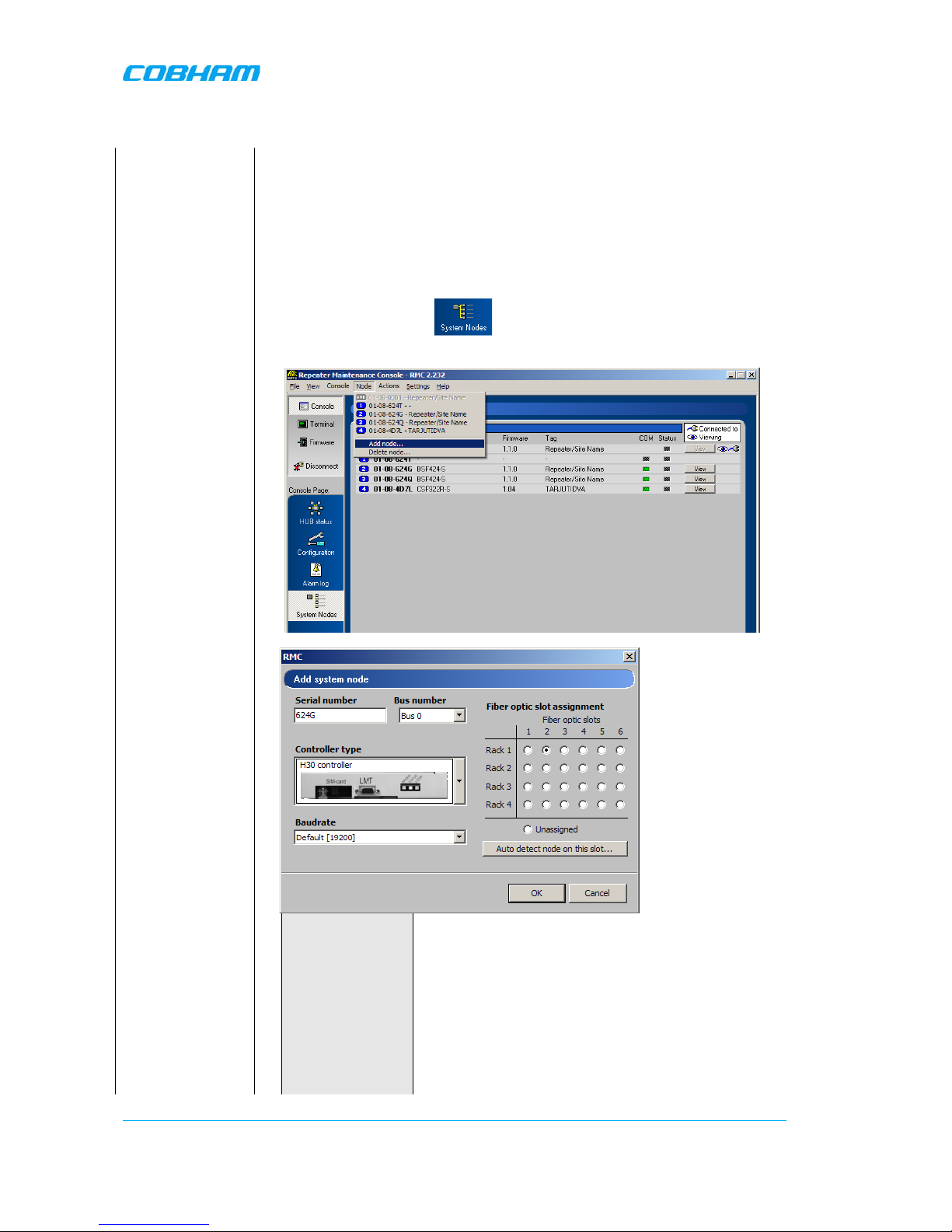
System.
Select “System Nodes”
Chose “Add node…” from the “Node” drop down menu.
Fill in the information for each repeater in the pop up window.
Serial number
The serial number consists of 4 letter and/or
digits. It is printed on the yellow label on the
repeater
Bus number When OMUs are cascaded they run on different
buses. OMU 1 and OM U 3
is on “bus “0 and OMU
2 and OMU 4 in on” bus 1”..
Controller type Select the correct repeater controller based on the
illustrations
Page 31

OPTICAL MASTER UNIT MARK I
PRODUCT DESCRIPTION AND USER’S MANUAL
Cobham Wireless – Coverage Date: 4-Jan-18 www.cobham.com/wireless
Document number:A1829300UM Rev. 3.1
Page | 25
Baud rate The default value changes when the controller
type is selected. (Other values are also available
for specific
situations not described in this
manual.)
Slot Assignment Click the button that corresponds to the fibre
optic converter the repeater is connected to.
NOTE: To confirm an installation or to check the
present configuration select a fibre optic converter and
click the button
.
If a
repeater is installed in this position the repeater serial
number will be presented.
Check the LEDs on
the Fiber Optic
Converters
The Fiber Optic Converter contains two optical alarm sources. These are
alarms for transmitted and received optical signal level.
Select HUB Status
Check the levels of
the received
optical signals via
the RMC
3.8 Balance the System
To estimate the signal levels in the system, a lin k budget should be prepared before the system is
made
operational. This sect ion provides background on calculat ing the required attenuation values along
the link and
describes how to set the attenuation value in the management application.
3.8.1 Downlink Path
The following two diagrams illustrate the attenuation levels for two types of installations:
• BS with separate Tx a nd Rx ports – for a total attenuation of 44dB (attenuator set to 0)
• BS with a common Tx and Rx port – for a total attenuation of 45dB (attenuator set to 0)
Also note the following:
• Any additional required attenuation (up to -21dB) is implemented via the Variable Attenuator.
• The input level to the laser should be ≤-3dBm composite power
NOTE: As the composite power in a multicarrier TETRA/TDMA/W-CDMA/LTE system is traffic dependent, the
maximum laser input power must be calculated for the traffic scenario that will require highest composite power.
After the downlink attenuation been set, the gain of the connected repeaters should be adjusted individually in
accordance to the relevant section in the manual for each repeater connected to the OMU.
The following diagram illustrates the attenuation level s for an installation with separate Tx and Rx
ports.
Page 32

OPTICAL MASTER UNIT MARK I
PRODUCT DESCRIPTION AND USER’S MANUAL
Cobham Wireless – Coverage Date: 4-Jan-18 www.cobham.com/wireless
Document number:A1829300UM Rev. 3.1
Page | 26
Fiber Fed
Repeater
e
o
OMU
BTS
Directional
Couplers (x2)
Loss in fiber
cable
10 Km
Variable
Attenuator
-14 dB
-30 dB
BTS Output
up to
- 21 dB
Variable
Attenuator
Basic Explanation of Attenuation Levels for BS with
SEPARATE Tx and Rx ports
up to
- 21 dB
-14 dB
Total attenuation = 44dB
Recommended power = -3dBm
RX
TX
-30 dB
BTS Input
Splitter
Measured Power
Combiner
The following diagram illustrates the attenuation levels for an installation with a common Tx and Rx port.
Fiber Fed
Repeater
Duplex
Filter
e
o
OMU
BTS
Loss in fiber
cable
10 Km
Variable
Attenuator
- 1 dB
up to
- 21 dB
Variable
Attenuator
Basic Explanation of Attenuation Levels for BS
with COMMON Tx and Rx ports
up to
- 21 dB
- 14 dB
Total attenuation = 45dB
Recommended power = -3dBm
BTS Output
RX/TX
-30 dB
Directional
Coupler
Splitter
Measured Power
- 14 dB
Combiner
To set the attenuation
Select “HUB Status”
Set the attenuation in
the downlink in this
box.
The signal level after
attenuation can be
monitored in the RMC
3.8.2 Fiber Loss Compensation
Activate the fibre loss compensation in both the downlink (from the OMU) and in the uplink (from the
repeaters) paths. See
3.9 Initiate Fibre Loss Compensation.
Page 33

OPTICAL MASTER UNIT MARK I
PRODUCT DESCRIPTION AND USER’S MANUAL
Cobham Wireless – Coverage Date: 4-Jan-18 www.cobham.com/wireless
Document number:A1829300UM Rev. 3.1
Page | 27
3.8.3 Uplink Path
The uplink gain setting of the OMU and connected repeaters affects the sensitivity in the connected
BTS sector and the connected repeater cells. The recommended method for setting up the system
below will give good noise performance in simple systems with a relative low number (less than six)
of connected repeaters per BTS sector.
For more complex systems, with many repeaters connected to the same BTS sector using multi-drop,
a more detailed system analysis is required to set up the system in an optimum way.
• Set the uplink attenuation in the OMU eq ual to the downlink attenuation.
• Set the uplink gain of each connected repeater equal to the downlink gain of the repeater (by
setting the attenuation value in the RMC for both links equal).
Select “HUB Status”
Seet the attenuation in
the uplink in this box.
3.8.4 Noise Considerations
To reduce the noise degradation of the base station, it is recommended to reduce repeater uplink
gain only. The repeater cells will in this case not be perfectly balanced, i.e. downlink can take higher
path loss than uplink. In typical systems where you want to cover for example a road tunnel by
tapping off a BTS nearby this small imbalance is less of a problem.
3.9 Initiate Fibre Loss Compensation
See section 3.3 Fiber Loss Compensation for information about this feature.
Start with the OMU
Choose “Actions/Perform Optical Loss Adjustment” from th
e drop down
menu.
Go through all
racks and all fibre
optic converters
one by one and
initiate the
compensation
process
First choose the rack and then the fibre opt ic converter.
In an OMU that contains only one sub
rack – this rack is called “Rack 1”
Additional sub-racks/slave OMUs that
are linked to the master OMU are
named “Rack 2, 3 and 4”.
Page 34

OPTICAL MASTER UNIT MARK I
PRODUCT DESCRIPTION AND USER’S MANUAL
Cobham Wireless – Coverage Date: 4-Jan-18 www.cobham.com/wireless
Document number:A1829300UM Rev. 3.1
Page | 28
Each fibre
optic converter is
numbered from left to right in each
sub-rack.
For each rack/fibre optic converter please wait for the system to respond.
The system will respond with a description as below.
In the response above the Status is “OK” (6 lines from the bottom).
If the system responds with an error message the fibre link need to be
checked. If there is nothing wrong with the link it is possible that the fibre
loss is too big for the system to be able to compensate for it.
Go through all racks and all fibre optic converters one by one and initiate
the compensation process.
Page 35

OPTICAL MASTER UNIT MARK I
PRODUCT DESCRIPTION AND USER’S MANUAL
Cobham Wireless – Coverage Date: 4-Jan-18 www.cobham.com/wireless
Document number:A1829300UM Rev. 3.1
Page | 29
NOTE: Earlier
repeater versions
If the OMU is connected to
repeaters of an earlier release,
which has a fibre optic con verter of
the type in the photograph, these
commands will not work.
Instead a default value needs to be
defined by using the command
OLC.
Please see OMU Command and
Attributes for more detailed
information regarding this
command.
The OLC value should be set to 6dB. This value ensures that the
amplification value on the link will be 0dB at 0dB optical loss.
Example
SET OLC 1:2 6
Adjusts the attenuation in the fibre opti c con vert er uni t i n ra ck 1, slot 2 to 6
dB.
Go through all racks and slots that are connected to a repeater of this kind
and send this command.
Continue with the
repeaters
Cho
ose “Actions/Perform Optical Loss Adjustment” from the drop down
menu.
The system will respond with a description as below .
This command does not exist in repeaters with the earlier type of fibre optic
converters, equivalent to the note above regarding OLC. For these repeaters
disregard this step.
Page 36

OPTICAL MASTER UNIT MARK I
PRODUCT DESCRIPTION AND USER’S MANUAL
Cobham Wireless – Coverage Date: 4-Jan-18 www.cobham.com/wireless
Document number:A1829300UM Rev. 3.1
Page | 30
3.10 Set up Remote Communication
The OMU can be configured with a wireless modem, a PSTN modem or an Ethernet link for the
remote communication.
3.10.1 Communication via Modem
The Control Module is r esponsible for enabling the power t o the modem, unlocking the SIM-card,
using the configured PI N-code and making sure the modem is logged in to the network correctly.
Depending on network configuration and modem usage, the modem might require different modem
initialization strings to work properly. This modem initialization string is set and verified during
repeater setup.
3.10.1.1 Modem Initialization
After a power failure, or upon user request, the Control Module performs a f ull initialization of the
modem. This consists of three steps:
• If the SIM-card in the modem has the PIN code enabled, the Control Module unlocks the PIN
code. In case wrong PIN-code is configured, the Control Module will not try to unlock the SIM
again until the PIN-code is changed. This avoids the SIM card being locked by a Control Module
repeatedly trying to unlock the SIM with the wrong PIN code.
• Once the SIM is unlocked, the Control Module waits for the SIM to log in to the ne twork.
Depending on signal quality and netw ork configuration this might take a while. The Control
Module will wait a configurable number of seconds (default 50 seconds) for the modem to login
to the network. In case no network is found, a modem power cycle will be initiated.
• When the modem is succe ssfully logged in t o the network, the Control Module confi gures the
modem with the modem initialization string as configured when sett ing up the remote
configuration. The modem initialization string is a network dependent string. The default string is
suitable for most networks, but some networks might require some tweaking of this string.
3.10.1.2 Monitoring Modem Connection
The Control Module constantly monitors the status of the modem connection to ensure that it is
working properly, and that the modem is logged in to the network.
In case the modem is not registered to the network, or the Control Module cannot properly communicate with
the modem, a power cycling of the modem is initiated, after which the modem will reinitialized.
3.10.1.3 Scheduled Modem Power Cycling
In addition to pol ling the modem to ensure t he repeater online status , the Control Module can b e
configured to perform an automatic power cycling on a scheduled time of the day. Power cycling the
modem ensures the latest network configuration for the modem, such as the HLR Update Inte rval
etc.
NOTE: By default, the scheduled modem power cycling is disabled.
Page 37

OPTICAL MASTER UNIT MARK I
PRODUCT DESCRIPTION AND USER’S MANUAL
Cobham Wireless – Coverage Date: 4-Jan-18 www.cobham.com/wireless
Document number:A1829300UM Rev. 3.1
Page | 31
3.10.2 Communication via Wireless Modem
There are two different ways of communication for a wireless (GSM) modem:
• Using data call / modem connection.
This requires the SIM-card in the modem to be configured
with data service.
• Using SMS to configure the repeater with simple text messages. SMS functionality is no t
implemented in this SW release.
The Element Manager always uses data call communication with the repeater, why all repeaters
being controlled by the AEM must have data service enabled on the SIM card.
Configuring the repeater to send alarms and reports via SMS it is still possible to establish data calls
to the repeater, as long as the SIM card is data service enabled.
3.10.2.1 Modem Configuration, not using GPRS
Select “Configuration”
and “Communication”
Select Data Call
Initialization string
Connect times
AEM addressed are
set via the AEM
• Select Data Call
• Set the modem initialization string. This string differs between
networks. Primary recommenda tion is AT+CBST=71,0,1;\Q 3. If remote
communication cannot be established try 7,0,1 or 0,0,1 or 7,0,3. For
more information please refer to the section on Troubleshooting
Remote Communication.
• Tick “Enable Automatic Modem Power Cycling” for the modem to be
power cycled once every 24 hours. Set the time at which the modem
should be tested. This function ensures that the repeater always is
logged in to the network.
2004-01-01
Page 38

OPTICAL MASTER UNIT MARK I
PRODUCT DESCRIPTION AND USER’S MANUAL
Cobham Wireless – Coverage Date: 4-Jan-18 www.cobham.com/wireless
Document number:A1829300UM Rev. 3.1
Page | 32
3.10.2.2 Modem Configuration, using GPRS
Select
“Configuration” and
“Communication”
Select GPRS
Initialization string
Connect times
AEM addressed are
set via the AEM
Configure GPRS
• Select GPRS
• Set the modem initialization string. This string differs between networks.
Primary recommendation is AT+CBST=71,0,1;\Q3
• Click “Enable Automatic Modem Power Cycling” for the modem to be
power cycled once every 24 hours. Set the time at which the modem
should be tested. This function ensures that the repeater always is
logged in to the network.
• Click on Configure…
Each parameter is described in
Common Commands and Attributes
, section
14 GPRS Configurat ions.
Set the Access Point Name. It needs to be defined by the telecom operator
Page 39

OPTICAL MASTER UNIT MARK I
PRODUCT DESCRIPTION AND USER’S MANUAL
Cobham Wireless – Coverage Date: 4-Jan-18 www.cobham.com/wireless
Document number:A1829300UM Rev. 3.1
Page | 33
Set Maximum Receive Unit and maximum Transmission Unit. These differ
depending on access type: 576 for GSM, 1476 for EDGE and 1500 for
WCDMA.
Click on Close, and then on “Yes”.
Wait for the modem to restart. This can take a few minutes.
When the modem settings are ready the LED turn green.
3.10.2.3 AEM Addresses
The Control Module can be configured with two different addresses (telephone numbers) to which
alarms and reports are delivered. In case the repeater cannot deliver alarms and reports to the
primary address, the next call will be made to the secondary address.
A fallback functionality is available, which me ans that the Control Module falls back to the prima ry
address after a configurable number of minutes. If this interval is set to 0, the fallback will not be
performed. A user can always force the Control Module to fall back to the primary address.
NOTE: When the repeater is integrated to the Axell Element Manager system, these addresses are set by the
AEM, why they need not be configured during site installation.
3.10.2.4 Modem Verification
When the remote co nfi guration has been se t up t he co mm unica tio n can be verified using the modem
feature of the RMC and dialling the data number. The remote communication is verified as soon as a
successful remote login to the repeater has been performed.
However, as a first step, it is recommended to verify that the modem is initialized correctly. After
configuring the modem using the RMC, make sure to initiate a power cycling of the modem. This is
done from the RMC menu.
Click on the drop-down menu
Actions, choose Power Cycle
Modem on Logout
An immediate power cycling is initiated after which the modem is initialized and registered onto the
network. The modem is now ready for remote access.
Page 40

OPTICAL MASTER UNIT MARK I
PRODUCT DESCRIPTION AND USER’S MANUAL
Cobham Wireless – Coverage Date: 4-Jan-18 www.cobham.com/wireless
Document number:A1829300UM Rev. 3.1
Page | 34
Ensure a successful configuration by observing the modem LED as described below.
For GSM modem LED descriptions, refer to
0 4.1.
Verify the remote communication either by having someone attempting to integrate the repeater
from the Axell Element Manager, or by dialing the repeater using the Repeater Maintenance Console.
NOTE: It is very important to dial the data number of the SIM. In case the voice number is dialled, the call is
answered, but almost immediately the call will be hung up.
3.10.2.5 SIM-card Using Single Numbering Scheme
If the network is configured using Single Numbering Scheme (SNS), some special considerations
apply.
The repeaters are by default configured so that networks using SNS always will have calls routed to
the data service in the modem. When dialling from within the network to a repeater having an SNSconfigured SIM will operate normally, si nce the call originator informs the system that the bearer is
of type DATA. However, when dialling from outside the network trying to connect to the repeater can
be difficult. Depending on the interface to the roaming network or to the PSTN network if an
analogue modem is used, the bearer type can default to voice. If the bearer is set to voice, the data
service cannot be converted to DATA, and a call setup cannot be completed.
NOTE: This is not a repeater related problem; the solution is to verify how the external network interfaces
handles the VOICE vs. DATA bearer type.
3.10.3 Communication via PSTN (Fixed) Modem
Also for PSTN modems data call shall be used.
Select “Configuration”
and “Communication”
Select Data Call
Initialization string
Connect times
AEM addressed are
set via the AEM
Tick “Enable Automatic Modem Power Cycling” for the modem to be power cycled
once every 24 hours. Set the time at which the modem should be tested. This
function ensures that the repeater always is logged in to the network.
2004-01-01
ATE0S0=0
Page 41
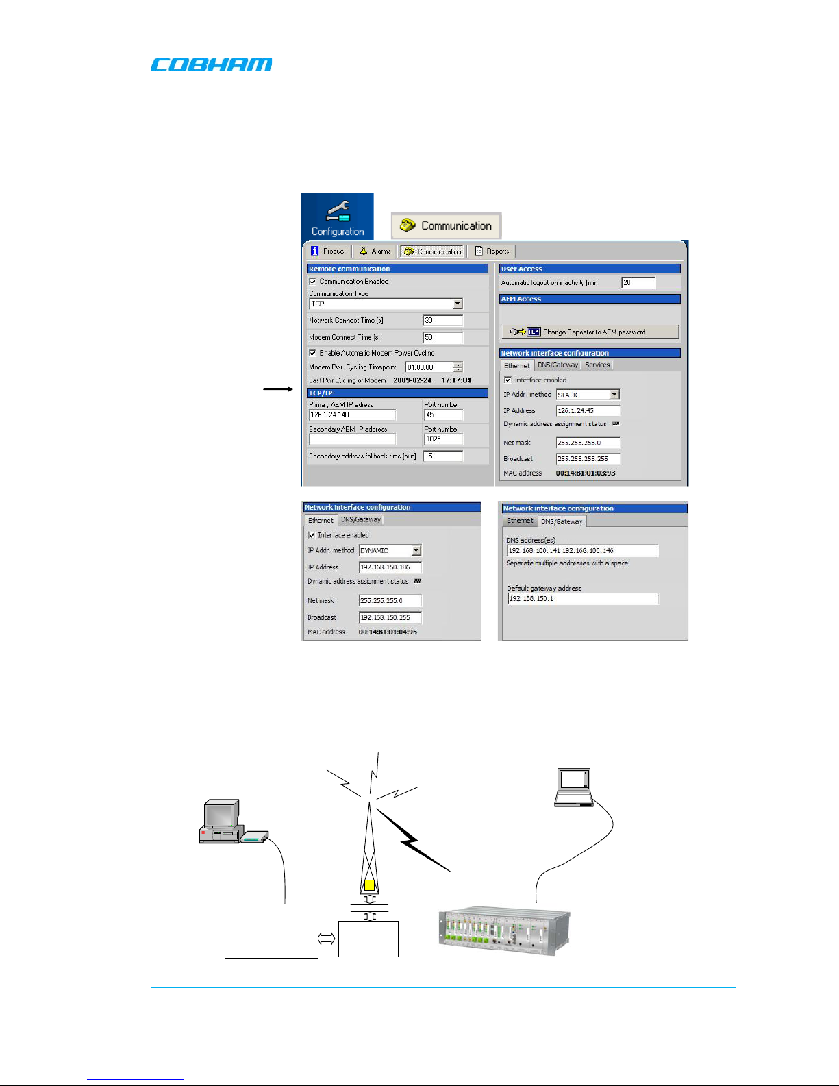
OPTICAL MASTER UNIT MARK I
PRODUCT DESCRIPTION AND USER’S MANUAL
Cobham Wireless – Coverage Date: 4-Jan-18 www.cobham.com/wireless
Document number:A1829300UM Rev. 3.1
Page | 35
3.10.4 Communication via TCP/IP and E thernet
A TCP/IP communication is run over a company’s network. Therefore each company needs to define
the details regarding the configuration, IP addresses, etc. For more information please refer to
Common Commands and Attributes
, section 13 Network Configurations.
Select
“Configuration” and
“Communication”
Set IP address and
other relevant
information here
In these screens the
Ethernet and/or DNS
Gateway parameters
can be set
3.10.5 Troubleshooting Remote Communication
Since many networks have their own “personality”, performing first time configuration of the remote
communication sometimes requires tweaking of the modem parameters.
This section describes some trouble shooting techniques if configuring the OMU for remote access fails.
Radio
LinkProtocol
(RLP)
BTS
LaptopLaptop
Control Module
in OMU
Switch
Centre
ModemModem
RS232
Interworking
Function Unit
(IFU)
Page 42

OPTICAL MASTER UNIT MARK I
PRODUCT DESCRIPTION AND USER’S MANUAL
Cobham Wireless – Coverage Date: 4-Jan-18 www.cobham.com/wireless
Document number:A1829300UM Rev. 3.1
Page | 36
This illustration is a simplified schematic of the remote commu nication between a GSM module in a n
OMU and an analogue modem. The analogue modem in the computer communicates with the
Interworking Funct ion Unit (IFU), whi ch is the GSM net work analogue netw ork interface . The call is
routed via the switch centre over the air interface to the data call number in the SIM-card of the GSM
module.
The Control Module is responsible for establishing connections with the Axell Element Manager, and
to answer incoming calls to the OMU.
As described in previous sections, the Control Module only accepts one login at a time, either via
Local Maintenance port (LMT) or modem connection. Hence, when verifying the remote access of the
OMU, it is important to log out from the OMU locally before trying to access the OMU remotely.
3.10.5.1 Direct Modem Access
To allow for advanced trouble shooting of the communications, it is po ssible to access the modem
directly via the Control Module from a laptop computer.
Log in to the OMU, either with RMC, or with a terminal emulation program, such as HyperTerminal™.
When the login is completed, select Terminal Mode, this will give access to the OMU command
prompt in the same way as with HyperTerminal.
When the OMU prompt is accessible, type in the command
ACCESS MODEM <Enter>.
When typing ACCESS MODEM, the controller will sen d all the characte rs that a re typed dire ctly out to
the modem port. All characters replied back from the modem will go directly to the LMT port and
back to the comput er.
To abort an ACCESS MODE M session, press thre e ‘-‘ in a row (all thre e within one second) to c ome
back to the OMU command prompt.
NOTE: When accessing the modem port the modem might be configured with “echo off”, meaning that the
characters entered will not be echoed back to the screen. In order to enable “echo”, press Enter.
Type
ATE1 <enter>
(invisible)
The modem replies with
OK
indicating that the echo is enabled. All characters entered will now be echoed back to the terminal
program.
Below is a list of handy modem commands for trouble shooting via Direct Modem Access. Please
refer to the modem manual for details on the commands below.
Command Description
ATE1 Enables the echo between the modem and the Control Module.
ATDT<Telephone
Number>
Causes the modem to dial <Telephone Number>. This can be used to
verify that the modem correctly can dial a remote modem.
ATA Answer incoming call
ATH Hang up call. Note, if being online to the remote peer, you need to go to
LaptopLaptop
RS232 cable
Control Module
GSM
Module
LMT Port
Page 43

OPTICAL MASTER UNIT MARK I
PRODUCT DESCRIPTION AND USER’S MANUAL
Cobham Wireless – Coverage Date: 4-Jan-18 www.cobham.com/wireless
Document number:A1829300UM Rev. 3.1
Page | 37
command mode to hang up the call. This is done by waiting at least one
second since last entered character, the n press +++ (three plus sign s), all
within one second. After one second, the modem will reply OK, meaning
that command mode is entered.
ATM0 Disables the loudspeaker in the modem
ATM1 Enables the loudspeaker in the modem
AT&W Saves the current mod em configuration into NVR AM. This means that this
configuration will be used directly after modem power up
AT&F Loads the modem factory configuration
ATZ Resets the modem, and loads the default settings as saved with command
AT&W
3.10.5.2 Trace Modem
For troubleshooting purposes it is possible to trace t he a ctual progress of i nitializi ng the modem . T his
trace is useful when having problems with the modem initialization.
Go to Terminal Mode and type
TRACE MODEM
To end session type CTRL-Z
3.10.5.3 Manually Answering Incoming Calls
It is possible to manually answer incoming calls witho ut involving the OMU software at all, to verify
that the remote access and the network itself works as intended. In order to verify the remote
communication, make sure to have someone stand by to dial up the OMU with a terminal emulation
program, for example HyperTerminal™.
Go in to Direct Modem Access as described earlier. When in direct access mode, ask the person
standing by to dial up the OMU.
As soon as a call is received, the text
RING
will repeatedly be displayed on the screen.
Type
Page 44
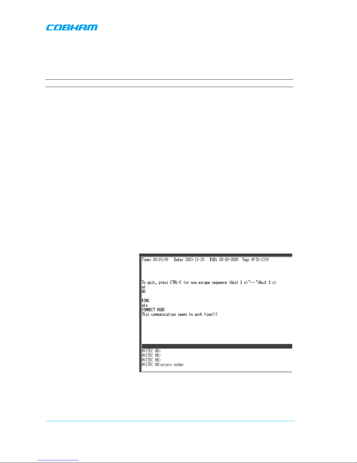
OPTICAL MASTER UNIT MARK I
PRODUCT DESCRIPTION AND USER’S MANUAL
Cobham Wireless – Coverage Date: 4-Jan-18 www.cobham.com/wireless
Document number:A1829300UM Rev. 3.1
Page | 38
ATA <enter>
This will inform the modem to answer (ATtention Answer).
When the connection is esta blished, a connect message will be displayed including the connection
speed. Sometimes the information comes together with some miscellaneous information, such as
error correction protocols etc.
NOTE: Make sure the remote peer dials the Data Call number
If the voice number is dialled instead of the data number, or if the modem contains an illegal modem
initialization string, the message
OK
or
NO CARRIER
will be displayed almost immediately.
Try to change the modem initialization string. The modem initialization string mainly used to
configure the remote communication is AT+CBST.
Successful modem initialization strings used by Axell W ir eless includes (most common first):
AT+CBST=71,0,1;\Q3
AT+CBST=7,0,1;\Q3
AT+CBST=0,0,1;\Q3
AT+CBST=0,0,1;\Q3
AT+CBST=7,0,3;\Q3
Once the modem initialization string is entered, try again to dial up the OMU. For details on the
different modem initialization strings, please refer to the modem’s user guide.
If the setup is successful, the connect message will be brought up;
CONNECT 9600
This means that an online connection is established to the remote peer. From now on, all characters
typed on the keyboard will end up on the remote peer’s screen. Similarly, all characters typed by the
remote peer will be displayed on the screen.
In the example, the incoming call was
successfully answered, and the remote
user entered the text message.
In order to come back to modem command mode, press +++ (three pluses) rapidly (within one
second).
Receiving
OK
means that the modem is back in command mode.
Page 45

OPTICAL MASTER UNIT MARK I
PRODUCT DESCRIPTION AND USER’S MANUAL
Cobham Wireless – Coverage Date: 4-Jan-18 www.cobham.com/wireless
Document number:A1829300UM Rev. 3.1
Page | 39
Type
ATH <enter>
This terminates the connection to the remote peer. The message
NO CARRIER
will be displayed.
3.10.5.4 Common Problems
Problem 1
When enabling the remote access for the OMU, the modem fails to log in to the network.
Solution
Signal strength from the donor site is too low. The signal strength can be read directly from the
modem. Go in to Direct Modem Access as described earlier. Use the command AT+CSQ (documented
below) to read out the signal strength.
In order to have good signal quality, Axell Wireless recommends that the signal strength should be better than 95 dBm. If signal strength is lower, try to adjust the antennas to get a better signal strength from the donor.
Documentation of +CSQ command from a modem’s manual.
Figure
3-1
Page 46

OPTICAL MASTER UNIT MARK I
PRODUCT DESCRIPTION AND USER’S MANUAL
Cobham Wireless – Coverage Date: 4-Jan-18 www.cobham.com/wireless
Document number:A1829300UM Rev. 3.1
Page | 40
In the example the reply to AT+CSQ is
0,7 meaning 7*2 dB above -113 dBm;
the modem detects a signal level of -99
dBm.
Problem 2a
OMU is configured properly, and answers the incoming call, but when trying to dial the OMU using an analogue
mode, no modem handshaking is heard from the dialling modem.
Problem 2b
When dialling the OMU, the OMU answers the incoming call, but no connection is established, and after a while
the OMU disconnects the call.
Solution
The most common cause is that the number called is the voice number of the SIM, not the data number.
Therefore, make sure to dial the data number.
If data call is used, the problem probably is an illegal modem initialization string.
In order to change the modem string, go to the OMU command prompt. Try changing the modem initialization
string and log out to let the controller reinitialize the modem.
If problem remains, try a few different modem initialization strings. Axell Wireless has been successful with the
following modem initialization strings:
AT+CBST=71,0,1;\Q3
AT+CBST=7,0,1;\Q3
AT+CBST=0,0,1;\Q3
AT+CBST=0,0,1;\Q3
AT+CBST=7,0,3;\Q3
Please refer to the modem manual for detailed description of the modem initialization strings.
Problem 3
It is possible to call the OMU from another GSM mobile, but not from an analogue modem.
Solution
This problem is most likely related to the modem configuration and/or the confi guration of the IFU
unit. Try to decrease the communications speed and make sure that the modem error correction is
supported by the IFU. Ve rify the IFU configuratio n to see if there are any know n problems with the
modem connections.
Problem 4
When dialling the OMU, or when the OMU is dialling the Element Manager, the connection is
terminated before the handshaking is completed.
Solution
When an OMU is answering an incoming modem call, or calling up the OMC to deliver an alarm or a
report, the OMU will wait a configurable number of seconds for the call to be established. If no
communication is established within this time, the call will be hung up. If this interval is set too low,
the handshaking is terminated too fast. In the RMC, verify the Modem Connect Time to see that it is
set to at least 30 seconds.
Page 47

OPTICAL MASTER UNIT MARK I
PRODUCT DESCRIPTION AND USER’S MANUAL
Cobham Wireless – Coverage Date: 4-Jan-18 www.cobham.com/wireless
Document number:A1829300UM Rev. 3.1
Page | 41
3.11 Integrate into the AEM
When the OMU has been installed at site and the remote communication has been enabled, the OMU
can be integrated to the Axell Element Manager. This is done by the operator of the AEM. After
entering the telephone number to the OMU, the AEM dials up the OMU, downloads all the OMU
parameters and statuses into a database. When all parameters have been downloaded, the AEM
configures the OMU with the telephone number where alarms and reports should be sent, and
optionally with a seconda ry telephone number where the repeater can dial in case connecti on to the
primary number fails.
When heartbeat reports and alarms are sent from the OMU to the AEM also the latest information
about the status and RF-configuration is included. This means that the AEM operator always has
information about t he current status in t he AEM database (and do not need to call the rep eater to
find this out).
Note! Once the OMU is integrated to the AEM, all changes to the OMU should preferably be done
from the Axell Element Manager in order to ensure that the database always contains correct
information.
3.12 Installation Examples
3.12.1 OMU Signal Tapped at BTS
3. An example of a site installation where the FR signal to the OMU is tapped off a BTS
Power Unit for -48 V DC
ODF
ODF
Fiber Fed
Repeater
Antenna or
Leaky feeder
Repeater Site
OMU Site
Splitters
BTS
Antenna
Modem
AEM
Duplex
Filter
Directional
couplers
Back-up Battery
Optional
LaptopLaptop
Rx
Tx
Page 48

OPTICAL MASTER UNIT MARK I
PRODUCT DESCRIPTION AND USER’S MANUAL
Cobham Wireless – Coverage Date: 4-Jan-18 www.cobham.com/wireless
Document number:A1829300UM Rev. 3.1
Page | 42
3.12.2 OMU Signal Source provided by Repeater
3. Example of a site installation where the FR signa l to the OMU is tapped off a repeater
Power Unit for -48 V DC
ODF
ODF
Fiber Fed
Repeater
Modem
AEM
Back-up Battery
optional
Coupler
Donor
Antenna
Server Antenna
Channel
Selective
Repeater
Antenna or
Leaky feeder
Page 49

OPTICAL MASTER UNIT MARK I
PRODUCT DESCRIPTION AND USER’S MANUAL
Cobham Wireless – Coverage Date: 4-Jan-18 www.cobham.com/wireless
Document number:A1829300UM Rev. 3.1
Page | 43
3.12.3 Multi-Sector Configurations - Up to Six Sectors
In this configuration, OMU I can support up to six sectors.
Requirements:
• OMU I physical configuration must incl ude a pair (UL/DL) of (factory installed) 6-way RF
Interface cards.
• Axell’s Point-of-Interface system – provides the RF signal interfaces between the signal sources
(BTS/BDA, et.) and the 6-way RF Interface cards.
To implement the multi-sector config ur ation
• Connect each pair of 6-way RF Interface Card ports to a RF interface output on the POI.
• The RF signal is routed to the corresponding Optical Conversion unit, where the 6-way RF
Interface Card ports are numbered 1 to 6 (from top to bottom).
6-way UL RF
Interface Card
6-way DL RF
Interface Card
RF simplex connections to Axell’s POI
Ports numbered 1 to 6 (top to bottom)
RF from port pair-1 routed to Optic Converter-1, from pair-
2
to Optic Converter-2, etc.
Page 50

OPTICAL MASTER UNIT MARK I
PRODUCT DESCRIPTION AND USER’S MANUAL
Cobham Wireless – Coverage Date: 4-Jan-18 www.cobham.com/wireless
Document number:A1829300UM Rev. 3.1
Page | 44
3.12.4 Changing UL Combiner and DL Splitter
Connections
Via these modules the RF in/out can be conne cted on the front of the O MU instead of the back, i f
needed. The connectors are QMA type. The modules can to be configured in two ways as shown in
the illustration below.
In Alternative 2 the input to the OMU is made via the QMA connectors marked RF in/RF out.
NOTE: In the illustration above only one Fiber Optic Converter is shown. The other converters are connected
accordingly. The configuration at delivery is Alternative 1.
RF in
DL out
UL in
RF out
RF in
DL out
UL in
RF out
RF in
DL out
UL in
RF out
Alternative 1
Alternative 2
Input to OMU
DL
OMU front side
DL out
RF in
UL in
RF out
Fibre port
RF in
RF out
Fibre Optic
Converter
Optional links
UL
Combiner
OMU back side
DL
Splitter
UL
Page 51

OPTICAL MASTER UNIT MARK I
PRODUCT DESCRIPTION AND USER’S MANUAL
Cobham Wireless – Coverage Date: 4-Jan-18 www.cobham.com/wireless
Document number:A1829300UM Rev. 3.1
Page | 45
4 TROUBLESHOOTING
4.1 Module LEDs
4.1.1 WDM Module LEDs
On the Fiber Optic Converter module there are six LED indicators; one for power status, one for
error, two for the data communication and two for the RF signals.
LED 1, Power, Green
On Unit is powered on
Off Unit has no power
LED 2, Error, Red
On Error detected
Off No error
LED 3, UL Data, Yellow
On
Communication via the opto module is
ongoing in the uplink direction
Off No communication
LED 4, DL Data, Yellow
On
Communication via the opto module is
ongoing in the downlink direction
Off No communication
LED 5, Opto Rx, Green
On Input opto level OK
Off Input opto level below threshold
LED 6, Opto Tx, Green
On Output opto level OK
Off Output opto level below threshold
ERR
PWR
UL
DATA
DL
DATA
OPTO
Rx
OPTO
Tx
SC/APC
PWR Indicates that the power is on
ERR Indicates that there is something wrong in the module
UL DATA Ongoing communication in the uplink direction
DL DATA Ongoing communication in the downlink direction
OPTO Rx Received signal on fiber channel
OPTO Tx Transmitted signal on fiber channel
Fiber link connection
Page 52

OPTICAL MASTER UNIT MARK I
PRODUCT DESCRIPTION AND USER’S MANUAL
Cobham Wireless – Coverage Date: 4-Jan-18 www.cobham.com/wireless
Document number:A1829300UM Rev. 3.1
Page | 46
4.1.2 Control Module LEDs
The Control Module has four LEDs which give information regarding the status
of the OMU.
If the OMU is configured for Ethernet communication the two LEDs
Modem Power and Modem Status do not fill any function and ca n be
disregarded.
Blue LED - Login
Quick flash Control Module switched on, someone logged in locally
and/or remotely
Off (except for a quick fla sh
every 10th second)
Control Module switched on, no one logged in
Off (permanent) Control Module switched OFF
Red LED - Status
Quick flash
Control Module switched on, one or more
errors/alarms detected
Off (except for a quick fla sh
every 10th second)
Control Module switched on, status OK
Off (permanent) Control Module switched off
Green LED – Modem Status
On
Depending on type of call:
Voice call: Connected to remo te party
Data call: Conne cted to remote party or ex change of
parameters while setting up or disconnecting a call
Flashing
(irregular)
Indicates GPSR dat a transf er. When a GPRS trans fer is
in progress the LE D goe s o n wit hin 1 se co nd a ft er d at a
packets
were exchanged. Flash duration in
approximately 0.5s.
75ms on/75ms off/75ms
on/3s off
One or more GPRS contexts activated
75ms on/3s off
Logged to network (monitoring control channels and
user interactions). No call in progress
600ms on/600ms off
No SIM card inserted, or no PIN entered, or network
search in progress, or o ngoing use r authe nticatio ns, or
network login in progress
Off Modem is off
Modem Status
Modem Power
Status
Login
Green LED – Modem Power
On Modem P ower is on
Off Modem Power is off
Page 53

OPTICAL MASTER UNIT MARK I
PRODUCT DESCRIPTION AND USER’S MANUAL
Cobham Wireless – Coverage Date: 4-Jan-18 www.cobham.com/wireless
Document number:A1829300UM Rev. 3.1
Page | 47
4.1.3 GSM Modem Behaviour
Note! This LED behaviour is valid only for GSM modems. Other modem types will be added in later editions.
Green LED – Modem Status
On Depending on type of call:
Voice call: Connected to remo te party
Data call: Connected to remote party or exchange
of parameters while setting up or disconnecting a
call
Flashing
(irregular)
Indicates GPSR data transfer. When a GPRS
transfer is in progress the LED goes on within 1
second after data packets were exchanged. Flash
duration in approximately 0.5s.
75ms on/75ms off/75ms on/3s off One or more GPRS contexts activated
75ms on/3s off
Logged to network (monitoring control channels
and user interactions). No call in progress
600ms on/600ms off
No SIM card inserted, or no PIN entered, or
network search in progress, or ongoing user
authentications, or network login in progress
Off Modem is off
Verify the remote communication either by having someone attempting to integrate the repeater
from the Axell Element Manager, or by dialling the repeater using the Repeater Maintenance Console.
NOTE: It is very important to dial the data number of the SIM. In case the voice number is dialled, the call is
answered, but almost immediately the call will be hung up.
Page 54

OPTICAL MASTER UNIT MARK I
PRODUCT DESCRIPTION AND USER’S MANUAL
Cobham Wireless – Coverage Date: 4-Jan-18 www.cobham.com/wireless
Document number:A1829300UM Rev. 3.1
Page | 48
5 MAINTENANCE
5.1 General
The system normally operates without any operator intervention or maintenance.
Should the system malfu ncti on, the condit ion o f the antenna syste ms as wel l as the co ntinuit y of t he
cabling should be checked before replacing any of the OMU units.
In the unlikely event o f a unit failure, the field replacea ble components (antenna unit, cables, etc.)
should be checked and replaced if faulty and the system restored.
A failed unit can be removed and replaced with a spare while the rest of the system (other OMUs) is
still in operation.
This product is equipped with Class 1 lasers, as per definition in EN 60825-1.
CAUTION!
Un-terminated optical receptacles may emit laser radiation. Do not stare into beam
or view with optical instruments.
NOTE: The power supply of the failed OMU should be isolated from AC mains and DC power before any module
is replaced.
5.2 Preventive Mai ntenance
The OMU does not require any preventative maintenance apart from changing the battery every three years.
CAUION!
• Risk of explosion if battery is replaced by an incorrect type.
• Dispose of used batteries according to local laws and instructions.
5.3 Product Disposal
Disposal of this product must be handled according to all national laws and regulations.
Page 55

OPTICAL MASTER UNIT MARK I
PRODUCT DESCRIPTION AND USER’S MANUAL
Cobham Wireless – Coverage Date: 4-Jan-18 www.cobham.com/wireless
Document number:A1829300UM Rev. 3.1
Page | 49
Appendix A : Specifications
RF Parameters
Frequency Bands 68-500 / 380 – 2200 MHz (*)
Gain Flatness Typical 2dB (p-p)
Nominal RF input power +10dBm composite power
Absolute maximum RF input power +23dBm composite power
Number of optical modules 1-6
Laser class Class 1
Optical Modules Electrical Specifications
Optical Wavelength:
Master 1310 ± 10 nm or 1330 ± 10 nm
Slave 1510 ± 3 nm or 153 0 ± 3 nm or 1550 ± 3 nm or
1570 ± 3 nm or 1590 ± 3 nm
Optical Output Power
Master/Slave +5 ± 2dBm
Maximum Optical Input Power +5 ± 2dBm
Output Power (Tx) max +7 dBm
Operating Temperature +5 ~ +45°C
Automatic fibre optic loss compensation Yes
Power Requirements
Power Requirements 230/115VAC, 50/60Hz 24/- 48VDC
Power Consumption Typical 50 W (fully equipped)
External Electrical Interfaces
Local Maintenance Terminal RS232
RF Ports N-type Connector Female
Optical Ports SC/APC
AC/DC Mains Input Plinth
External alarms Plinth
Modem connector RJ45 or RJ11
Modem antenna connector SMA
Ethernet connector RJ45
Mechanical Specifications
Dimensions (w x h x d) 17.5 x 5.2 x 11.4 in (444 x 132.5 x 291 mm) 19”
rack
Weight 15 kg (fully equipped)
IP rating IP20
Reliability Specifications
Lifetime (MTBF) >70,000 Hrs
Specifications are subject to change w ithout notice
(*) Support up to 2700MHz is available as an option.
Page 56

OPTICAL MASTER UNIT MARK I
PRODUCT DESCRIPTION AND USER’S MANUAL
Cobham Wireless – Coverage Date: 4-Jan-18 www.cobham.com/wireless
Document number:A1829300UM Rev. 3.1
Page | 50
Appendix B: F/O Cleaning Procedure
NOTE: The process is demonstrated on an OMU F/O module and is similar to all F/O equipment supplied by
Axell.
Tools:
Tool Description Illustration
Fibrescope con nected to a PC running the appro priate
viewing software.
It is highly recommended that some form of fibre
viewing equipment such as a Fibrescope is used to
ensure that all fibre connections are clean before
termination; failure to do so could result in poor syste m
performance
Lint-free swabs (box), Axell P/N 99-000127
Lint-free wipes (pack) Axell P/N 99-000125
Fujikura “One Click” cleaner, Axell P/N 98-900004.
99% isopropyl alcohol (can), Axell P/N 99-000126
Cletop type S Cassette Cleaner, Axell P/N 98-900001
Page 57

OPTICAL MASTER UNIT MARK I
PRODUCT DESCRIPTION AND USER’S MANUAL
Cobham Wireless – Coverage Date: 4-Jan-18 www.cobham.com/wireless
Document number:A1829300UM Rev. 3.1
Page | 51
Dry Cleaning
ATTENTION!
Invisible laser radiation might be emitted from disconnected fibres or connectors. Do
not stare into beams or view directly with optical instruments.
1. Before cleaning the optical connectors on the OMU it is advisable to clean the connector of the
mating cable being attached to the optical port.
An unclean optical connector is often the cause for reduced system performance. A bit of dust or
oil from a finger can easily interfere with, or block light. Fortunately, it is very easy to clean the
connector. Be sure to use the correct procedure for the given connector. When disconnected,
cap the SC/APC connector to keep it clean and prevent scratching the tip of the ferrule.
Use a product specially designed
for the
purpose, such as the Cletop type S Cassette
Cleaner.
2. Begin by dry cleaning the F/O bulkhead connector (shown below is the Fujikura One-Click in use).
IMPORTANT
Always make sure there is a way of inspecting the connector after cleaning. Cleaning can
actually leave the end-face in a worse condition, since alcohol residue is one of the most
difficult contaminants to remove.
3. Remove the protective cap from the
cleaning-head end of the “One Click”
cleaner, lift the protective end-cap on
the fibre connector and offer-up the
end to the fibre connector
Page 58

OPTICAL MASTER UNIT MARK I
PRODUCT DESCRIPTION AND USER’S MANUAL
Cobham Wireless – Coverage Date: 4-Jan-18 www.cobham.com/wireless
Document number:A1829300UM Rev. 3.1
Page | 52
4. With the cleaning-head end fully
engaged in the connector, push
until an audible “click” is heard
5. Without fully withdrawing the cleaning
head end push it in again twice more,
each time until an audible “click” is
heard.
6. Withdraw the “One Click” cleaner and
replace the protective end cap.
7. Inspect the fibre connector using a Fibrescope. On the PC monitor, verify that there is no
contamination present on the connector end-face.
8. If the connector is dirty, clean it with a wet cleaning technique followed immed iately by dry
cleaning. This is to remove any remaining residue from the wet clean (the following steps
demonstrate a wet cleaning technique).
Page 59

OPTICAL MASTER UNIT MARK I
PRODUCT DESCRIPTION AND USER’S MANUAL
Cobham Wireless – Coverage Date: 4-Jan-18 www.cobham.com/wireless
Document number:A1829300UM Rev. 3.1
Page | 53
Wet Cleaning
ATTENTION!
Invisible laser radiation might be emitted from disconnected fibers or connectors. Do not
stare into beams or view directly with optical instruments.
1. Lightly moisten a new lint-free wipe with 99% isopropyl alcohol. (Step 1 below).
Tip: Have a dry lint-free swab available for immediately drying after performing the wet-cleaning.
2. Lightly press and turn a clean lint-free swab in the moistened area of the wipe to moisten the
swab. It is important that the swab is not too wet. (Step 2 below).
3. Insert the moistened lint-free swab into the bulkhead adapter. Lightly press and rotate several
times in the same direction. (Step 3 below).
Wet-Cleaning Technique
4. Immediately use a dry lint-free swab to clear any remaining alcohol residue.
NOTE: Do not re-use any of the wipes and/or swabs. Dispose of them properly.
5. Follow steps 3 to 6 of Dry Cleaning above
6. Re-inspect the fibre using the Fibr escope. On the PC monitor, verify that there is no
contamination present on the connector end-face.
7. If the fibre is still dirty, go back to step 1 (Wet Cleaning) and repeat the entire process.
NOTE: The entire wet/dry cleaning cycle should only be used twice, if the fibre is still dirty after two cycles of
wet/dry cleaning seek advice from the Cobham Wireless Support Desk.
Step 1 Step 2 Step 3
Page 60

OPTICAL MASTER UNIT MARK I
PRODUCT DESCRIPTION AND USER’S MANUAL
Cobham Wireless – Coverage Date: 4-Jan-18 www.cobham.com/wireless
Document number:A1829300UM Rev. 3.1
Page | 54
Appendix C: EU Declaration of Conformity
 Loading...