


Page 1 Specifications subject to change without notice
NetLink Users’ Manual
Covers the following products:
NetLink Front End Unit (NETLINK) v2.4
NetLink Windows Application (NETEPLAY) v2.4
NetLink Smart Phone Application (NETSMART) v1.0
Users’ Manual
Version 2.4.1
23 September 2009
Cobham Surveillance
Domo Products
11 Manor Court, Barnes Wallis Road, Segensworth,
Hampshire, PO15 5TH, England
T: +44 (0)1489 566 750
F: +44 (0)1489 880 538

2
1 Table of Contents
1 Table of Contents.............................................................................................. 2
2 About this Manual............................................................................................. 4
3 Introduction...................................................................................................... 5
4 Warranty and Support ....................................................................................... 6
4.1 Warranty Cover ....................................................................................... 6
5 Safety, Compliance and Approvals .................................................................... 7
5.1 Safe Operating Procedures ....................................................................... 7
6 NetLink Product Overview ................................................................................. 8
6.1 NetLink Front End Unit Versions ................................................................ 8
6.2 NetLink User Interfaces............................................................................. 9
6.3 NetLink Systems.................................................................................... 11
6.4 NetLink Modes....................................................................................... 12
7 NetLink Front End Unit.................................................................................... 14
7.1 Which Model Do I Have .......................................................................... 14
7.2 Controls................................................................................................ 14
7.3 Indicators.............................................................................................. 15
7.4 NetLink Unit Connections ........................................................................ 15
7.5 Installation Notes ................................................................................... 18
7.6 Network Requirements ........................................................................... 18
7.7 Powering on the System ......................................................................... 19
7.8 Controlling the NetLink Unit ..................................................................... 19
8 Getting Started and Basic Operation................................................................ 20
8.1 NetLink Connections .............................................................................. 20
8.2 IP Setup via RS232 Control Port .............................................................. 21
8.3 Licensing the Net-Link application ............................................................ 24
8.4 Initial Application Setup........................................................................... 24
8.5 Logging in to the NetLink......................................................................... 25
9 Using the NETEPLAY Windows Application ..................................................... 29
9.1 Changing the Application Network Mode ................................................... 29
9.2 Changing the NetLink Network Mode ........................................................ 30
9.3 Connecting to NetLink Units .................................................................... 31
9.4 Application Work Areas........................................................................... 33
9.5 Main workspace area.............................................................................. 34
9.6 Content/connections area........................................................................ 35
9.7 Playback controls area............................................................................ 36
9.8 Controlling PTZ Cameras ........................................................................ 38
9.9 Controlling Kramer Video Switches ............................................................. 41
9.10 Input Slot Routing .................................................................................. 41
9.11 Input Source Setup................................................................................. 42
9.12 Retrieving a NetLink Unit’s Properties ....................................................... 44
9.13 Setting the NetLink Time and Date .............................................................. 44
9.14 Setting up Network Parameters................................................................ 45
9.15 Closing a connection .............................................................................. 48
9.16 Rebooting a NetLink Unit ........................................................................ 48
9.17 Managing user accounts ......................................................................... 49
9.18 NetLink Data Encryption Management ...................................................... 52
9.19 Toolbar and menus ................................................................................ 54
9.20 Toolbar buttons...................................................................................... 58
9.21 Live Thumbnail Streams.......................................................................... 59
9.22 The NetLink Store and Forward System .................................................... 61
10 Using the NETSMART Smartphone Application............................................. 66

3
10.1 Installing the NETSMART Application ....................................................... 66
10.2 Enabling the Data Connection.................................................................. 68
10.3 Starting the NESTSMART Application....................................................... 68
10.4 Connecting to a NetLink.......................................................................... 69
10.5 Starting a Live Stream ............................................................................ 72
10.6 NETSMART PTZ Controls....................................................................... 73
10.7 User Management.................................................................................. 73
10.8 Recording and retrieving Video ................................................................ 73
11 Technical Reference .................................................................................... 78
11.1 NetLink Unit Connector pin-outs............................................................... 78
11.2 Triggers Cable....................................................................................... 80
12 Setting up A Server Based 3G NetLink System.............................................. 81
12.1 Introduction ........................................................................................... 81
12.2 Setting up the NetLink and its 3G Modem.................................................. 81
12.3 Setting up the Server and its ADSL modem ............................................... 83
12.4 Setting up the NETEPLAY Application ...................................................... 83

4
2 About this Manual
This manual describes the operation of the domo NetLink product. The
manual is divided into the following main sections:
• NetLink Overview
This section gives an overview of the NetLink system and explains
how it works in various usage scenarios.
• NetLink Front End Unit
This section describes how to connect and set up the NetLink front
end unit.
• Getting Started and Basic Operation
This section is a quic
k-start guide, designed to help the user get a
NetLink system going.
• NetLink Windows Application
This section explains how to use the Windows application to interact
with NetLink front end units. Most of the NetLink functions are
explained in detail in this part of the manual.
• NetLink Smartphone Application
This describes how to use the NetLink Smartphone application to
interact with NetLink front end
units.

5
3 Introduction
The NetLink product allows domo equipment to be connected to IP
networks. In its basic form the NetLink can be connected to the output of
any standard domo transmitter or receiver, and translates the signal into
a streaming video service. NetLink can be set to stream at rates suitable
for either private or public networks.
In private network mode it will stream full frame rate, full resolution video
for
maximum quality. When connected to public networks where the
data rates are limited, it will produce a reduced frame rate and resolution
stream at a data rate appropriate for the network.
NetLink uses AES128 or AES256 encryption to ensure the security of
the transmission. These transmissions can then be decoded in software
using the NETEPLAY application or in hardware using the domo
NETIPHW IP Hardware
decoder. The NetLink also has two RS232
outputs suitable for controlling PTZ cameras and video switches.
NetLink is fitted with a USB interface for external devices.
NetLink complements the domo SOLO4 and SOLO2 product range,
which enable the user to build wireless digital microwave video systems.
The standard domo SOLO4 and SOLO2 Encoder/Transmitter and
Receiver/Decoder products have been designed to
provide rugged
point-to-point links for high quality full frame rate video, and audio, even
in non line of sight and urban environments.

6
4 Warranty and Support
4.1 Warranty Cover
domo offers a 12 month standard product warranty. During this period,
should the customer encounter a fault with the equipment we
recommend the following course of action:
• Check the support section of the website for information on that product
and any software/firmware upgrades. If fault persists;
• Call our support line and report the fault. If fault persists and you are
informed to return the
product please obtain an RMA number from the
domo support department, and ship the equipment with the RMA
number displayed and a description of the fault. Please email the
support section the airway bill/consignment number for tracking
purposes.
• If you have extended warranty provisions then domo will send an
immediate advance replacement to you. Under most circumstances
this must be returned once the
fault item is repaired.
Depending on the nature of the fault domo endeavour to repair the
equipment and return it to the customer within 14 days of the item
arriving at our workshops.
Obviously it is impossible to cater for all types of faults and to manage
100% replacement part availability, and delays are sometimes
inevitable. This is why domo recommend that its customers take out an
extended warrant
y (which includes advanced replacement of faulty
items), and/or hold a basic level of spare parts, which can be held by
domo on the customer’s behalf.
Please contact domo for details of packages that can be tailored to meet
your individual needs, whether they are service availability, technical
training, local geographic support or dedicated spares holdings.

7
5 Safety, Compliance and Approvals
5.1 Safe Operating Procedures
• Ensure that the power supply arrangements are adequate to meet the
stated requirements of each NetLink, SOLO4 or SOLO2 product.
• Operate within the environmental limits specified for the product.
• Do not subject the indoor equipment to splashing or dripping liquids.
• Only authorized, trained personnel should open the product. There are
no functions that require the User to gain access to the in
terior of the
product.

8
6 NetLink Product Overview
6.1 NetLink Front End Unit Versions
NetLink is currently available in three versions: NETLINK, NETLINK-AV
and NETLINK-DVRI.
All NetLink versions are available with ABS, AES-128 and AES-256
scrambling (AES is subject to export restrictions).
When using NetLink with domo wireless links, the full quality video stays
in encrypted digital form throughout the chain. The video is only
decrypted and decoded when it reaches the end user, minimi
sing
quality loss and security issues.
NETLINK
In its basic form, NetLink extends the capabilities of domo SOLO4
wireless links by adding internet transmission capabilities. The diagram
below shows a typical NETLINK setup.
At the receiver end local users can view the transmission in the usual
way, using a monitor and speakers. Remote users can log via the
internet and view a live thumbnail stream from virtually any location in
the world. To use a PTZ camera with this setup, a domo telemetry link
is required to send the PTZ commands wirelessly to the camera.
NETLINK-AV
This version comes with its own video and audio inputs, so it works as a
stand alone system. It can also be used with domo SOLO4 links, as in
the diagram above.
In this version the camera is local to the NetLink unit, therefore a PTZ
camera can be used and plugged directly into the NetLink, without the
need for a telemetry link. Users can control the camera via the internet
connection.

9
NETLINK-DVRI
This is the fully featured version. It can be used either with domo
SOLO4 wireless links or with a camera plugged in directly. It has all the
features of the NETLINK and NETLINK-AV, plus the following:
• Internal hard disk for recording audio and video information.
• Selective downloading of recorded video to minimise download
time.
• Trigger-based recording. The unit has three trigger inputs that
can b
e used with a variety of sensors. When using triggers, the
unit can be set to only record when a trigger is active, saving
hard disk space and download time. Talk to your domo
representative about available sensors.
• Pre-roll function records up to a minute before a trigger, so the
event that caused the trigger can be clearly seen.
• Internal back-up battery for clean shut down of hard disk in the
event
of power failure.
• The hard disk records trigger times, thumbnail streams and full
quality audio and video, all time-stamped to the internal clock.
• Live streaming, hard disk recording and file downloading can
be run simultaneously.
6.2 NetLink User Interfaces
The NetLink applications allow users to interact with remote front end
units from their computers or portable devices. Before any interaction
can take place, the user has to log in to the remote unit (this is explained
in detail in later sections).
There are three levels of user accounts: supervisor, gold and silver.
The supervisor user has access to all the features, including set up
menus. To avoid
inadvertently changing a vital parameter that could
make the unit inaccessible remotely, this account should only be
used when setting up a unit. There is only one supervisor account.
Gold users have access to every operational feature, except set up
functions. A gold user can delete files on the remote hard disks.
Silver users have read-only access to remote units, i.e. they are not
allowed to delete
files or change recording times.

10
There are currently two types of user interface available: the
NETEPLAY Windows application, and the NETSMART Smartphone
application.
NETEPLAY
The NETEPLAY version is the fully-featured NetLink user interface. It
runs on Windows XP and Vista computers, and gives access to the full
set of NetLink features. It is designed to look familiar to users of
standard video surveillance systems. The screen can be split in
to
multiple windows, and each window can play a live stream or a
downloaded one.
NETSMART
This version runs on Smartphones
and similar mobile devices based on
Windows CE.
It has a reduced set of functions
compared to NETEPLAY, but still
allows the user to view live streams
and download pre-recorded ones.

11
6.3 NetLink Systems
NetLink systems can be a simple as a single front end unit accessed by
a single user, or as complex as a multiple source–multiple user system
with several connections simultaneously active. Some example NetLink
systems are shown in the diagrams below.
Mobile NetLink and User via 3G
In this example the NetLink unit is connected to the internet via 3G, so it
can be installed in a moving or parked vehicle, or any location where
ADSL
lines are not available. The user is also on the move, and uses a
3G-enabled Smartphone to receive live images from the NetLink unit.
NetLink units can be supplied with pre-configured, ready to go 3G,
ADSL, cable or satellite modems.
Multiple NetLinks and users via Broadband and 3G
In this example, a mix of 3G and broadband connections are used at
both the NetLink and the user ends. Multiple units are deployed
simultaneously, and multiple users are connected.
The connections shown here are all direct between the units and the
users. It is also possible to use a server to act as in-between in more
complex systems. Ask your domo representative about server-based
NetLink systems.

12
6.4 NetLink Modes
The NetLink Front End unit operates in three different modes:
1) Private Network Mode
2) Public Network Server Mode
3) Public Network Client Mode.
The operating mode is typically set up at the factory depending on the
type of system purchased, but can be changed at any time by the
customer to adapt the unit to different uses.
Private Network Mode
In this mode, the NetLink unit behaves like a domo NetStream unit: It
multic
asts a full quality, full frame rate audio/video/data stream onto a
private network. The multicast can be received and played back on a
PC using the domo software decoder, or it can be output as composite/
S-Video, using the domo IP Hardware Decoder.
Due to the high transmission bit rates and multicasting, this mode
cannot be used over the internet. The main benefit of multicasting is that
a single tran
smission can be viewed simultaneously by all the users on
the network, and in real time.
Public Network Server Mode
In this mode, NetLink can be used over a public contended network, like
the internet. The unit will stream reduced resolution thumbnails, using
the available bandwidth. If the DVRI option is purchased, NetLink will
locally record both the thumbnails and full quality video, along with any
triggers applied to its trigger inputs. These can then be downloaded in
non-real time. See the NetLink Windows appl
ication manual for more
details.

13
In this mode the NetLink unit acts as a server, therefore users can
connect directly to it without having a server in between. This mode is
recommended when using ADSL or cable modems. Dynamic DNS is
supported, therefore the unit can always be located on the internet,
regardless of its current IP address. This mode can also be used when
a 3G connection with a fixed IP address is available. Speak to you
r
domo representative about companies that supply fixed IP 3G SIM
cards for your 3G modem.
Public Network Client Mode
This mode is similar to Public Network Server Mode, but the NetLink
unit acts as a client rather than a server. In this mode, an in-between
server is required, and all NetLink units and users connect to the server.
This mode is needed when using standard 3G data cards, as service
providers do not allow inbound connections on standard data services.
Client mode is also useful when a single live stream
needs to be viewed
simultaneously by multiple users. In this case the server receives the
live stream from the NetLink, and forwards it to as many users as its
bandwidth will allow.
The server is designed to run as a command-line executable on a
windows PC, and is supplied by domo either as software only, or as a
fully set up PC. The server must have a fixed IP address and it must
visible on the internet. When a NetLink unit is set up in client mode,
the server’s fixed IP address must be entered in the NetLink unit.
When NetLink is set up in this mode, both the NetLink unit and th
e
Windows application connect to the server.

14
7 NetLink Front End Unit
7.1 Which Model Do I Have
NetLink units are marked with labels similar to the one shown below.
The product code is at the top of the label, and the serial number is
below the bar code.
The domo product code can be referenced in the table below.
Product
Code
Product
Accompanying items
NETLINK
Private/public network
streamer.
Power supply unit
Cables:
Combined Chaining + control
for SOLO4 products
A/V Out
RS232 Control
NETLINK-AV
As above, plus
composite video and
stereo audio inputs.
As above, plus A/V input cable
NETLINK-DVRI
As above, plus store and
forward capabilities and
triggers
As above, plus internal 250GB
hard disk and backup battery.
7.2 Controls
There are no physical controls on the NetLink Front End unit, as the unit
is controlled through the network connection.
If the IP address of the Ethernet port is not known, first follow the procedure described in
the previous section.

15
7.3 Indicators
There are 2 LEDs on the NetLink unit; their meaning is explained in the
table below.
LED Label
Colour
Meaning / Use
RUNNING
Green
Will light 40 seconds after applying power. Indicates power is on
and unit is fully operational.
NETLINK-DVRI only: flashes when unit is powering down.
RECORDING
Green
Recording to hard disk (NETLINK-DVRI only)
7.4 NetLink Unit Connections
This section describes how to connect the domo NetLink product.
The drawings below show the Front End Unit’s front and rear panels.
Each connection is described in detail in the following section.
NetLink Front Panel
Video Monitor and
Stereo Speakers
SOLO4 Transmitter
or Receiver
Composite video and stereo
audio sources (NETLINK-AV
and NETLINK-DVRI only)
Up to three trigger
sources (NETLINK-DVRI
only)

16
NetLink Rear panel
Ethernet Connection
Connect this port to a compatible 100Base-TX switch or modem. Use of
10Base-T networks for full rate video streaming is not recommended, as
the network may not be capable of supporting the data rates, especially
when high bit-rate video is streamed.
Connector
Signal
RJ45 socket
10Base-T / 100Base-TX, single or full-duplex, auto-
negotiation, auto MDI/MDIX feature for automatic cross-
over of Ethernet cables
Some poorly designed network appliances sold as 100Base-TX compatible are
incompatible with multicast streams, and may cause the streaming to fail. Disconnect any
such devices from your private network if you are experiencing streaming problems.
Power
Supply
LAN Switch or
ADSL/Cable/3G Modem
PC Serial
Port
PTZ Cameras or
Kramer video switches

17
A/V In Connection (NETLINK-AV and NETLINK_DVRI only)
Connect the supplied A/V input cable to this port. The other end of the
cable has a BNC for connecting the chosen video source, and two RCA
connectors for audio sources.
Connector
Signal
Video BNC
75 ohm composite video input, PAL or NTSC
Audio RCA
Analogue stereo audio inputs, line level
Typically the video source will be a high quality surveillance camera.
A/V Out Connection
Connect the supplied A/V breakout cable to this port. The other end of
the cable has a BNC for connecting to the chosen video display device,
and two RCA audio connectors for audio monitoring.
Connector
Signal
Video BNC
75 ohm composite video output, PAL or NTSC,
depending on incoming video stream
Audio RCA
Analogue stereo audio output, line level
Typically the video display device will be a high quality monitor.
Triggers (NETLINK-DVRI only)
The NetLink unit can be set up to only record when one or more of the
trigger inputs are active. Triggers can be set up to active high or active
low, or can be disabled.
Connector
Signal
Triggers
3 standard LVTTL level inputs, 5V compatible.
Must be pulled high via a 4k7 resistor or low via
a 1k resistor, depending on application.
1 LVTTL output

18
Control Connection
This port is used to discover the unit’s network settings or to give the
unit an IP address. See Initial IP Setup section.
Connector
Signal
RS232 socket
Standard RS232 signal levels, RX, TX and
ground only.
DC Power
The NetLink unit is powered from a nominal 12V DC supply.
As standard domo supply an AC to DC converter, terminated with a
LEMO connector on the DC power output. Push the LEMO plug into the
socket labelled ‘12V’, taking care to align the connectors. Connect the
AC adapter block to your local mains electricity supply, noting the mains
supply requirements detailed on the adapter.
The 12V DC input has th
e following characteristics.
• Input Voltage Range – 10V to 18V, reverse voltage protected. The
unit will work with a lower input voltage, but the internal battery fitted
to NETLINK-DVRI units will not be charged.
• Current Draw – 1.0A at 12V (varies depending on number of
options fitted)
domo can supply optional bare DC power leads, for connection or
hardwiring to other DC sources. The domo part number
is CABDC3
7.5 Installation Notes
The domo NetLink unit is a professional digital video streamer designed
to multicast audio/video streams over private networks or to send
thumbnail streams over public networks like the Internet. Live multicast
streams can be played back by using a domo NetLink Player
(NETEPLAY or NETSMART), Software Decoder (NETSWDR), or
Hardware IP Decoder (NETIPHW).
The NetLink unit is self-cooling; howev
er it should be mounted in a
ventilated environment. Forced air cooling is not required. Adequate
clearance on either side the receiver (5cm) should be allowed for
ventilation.
7.6 Network Requirements
The NetLink unit should be connected to an Ethernet network or modem
with the following characteristics.

19
Capacity
For live streaming the network should have sufficient capacity to support
the required bit rate, plus some spare capacity.
Live multicast streaming will only work on private networks, as internet
service providers block any multicasts, unless specific arrangements for
bandwidth and scope are made in advance.
Each domo video service occupies between 600kb/s and 4.8MB/s
depending on mode. Typical
occupation is 2.4Mb/s. Therefore the
network must have sufficient capacity to support these services and also
any other data on the network. Contact domo technical support for
more details on this subject.
To use NetLink on public networks, a cable, ADSL or 3G modem with
an Ethernet port is required. This can be connected directly to the
Ethernet port on the NetLink unit.
Protocols
For live multicast s
treaming the network should support multicast UDP
streaming protocols.
For thumbnail streaming on public networks, the external modem should
act as a DHCP server to give the appropriate IP address to the NetLink
unit. If the modem acts a router, appropriate routes must be set up to
allow NetLink traffic though.
7.7 Powering on the System
All external connection to the NetLink unit should be made, as described
in the previous se
ctions, before proceeding to power on the system.
On powering the NetLink unit, the system will boot in approx. 45
seconds, although audio and video outputs may start working within a
few seconds of applying power. When the boot process is complete, the
RUNNING LED on the front panel will turn on.
7.8 Controlling the NetLink Unit
The RS232 CONTROL port and a computer running Tera Term or
Hyper Terminal can be used in all modes to se
t up basic parameters, as
described in the next section. For full access to the system’s features a
NETEPLAY or NETSMART application is needed.

20
8 Getting Started and Basic Operation
This section describes the basic steps required to set up a NetLink
system.
This procedure can also be followed to restore a NetLink to a working
state after the wrong settings have been applied.
This set up procedure is carried out with both the NetLink and the PC
running the NETEPLAY application connected to the same network.
The procedure consists of the following steps:
• Connect inputs and outputs t
o the NetLink box.
• Discover the current IP address of the unit and/or change it to
the correct value if required.
• If the NetLink is not in Public Network Server mode, set it to that
mode.
• Log in using the NETEPLAY application and select the correct
video source.
• Start a live stream.
8.1 NetLink Connections
Make sure all the connections described here are in place before
moving on to the next section.
Video source connection
• If you have a NETLINK model, connect a SOLO4 transmitter or
receiver to the input marked Chaining. Make sure the SOLO4
TX or RX has a valid input, and that its chaining output is active.
Also, make sure scrambling is turned off.
• If you have a NETLINK-AV or NETLINK-DVRI, you can either
connect a SOLO4 unit as above, or you can connect a camera
directly to socket marked A/V In.
Network connection
Connect the Ethernet port to your local network, or directly to the
computer you will be using to set up the unit.
Serial Port Connection
You will not need this connection if you already know the IP address
and ID of your NetLink unit.
Connect the port marked Control to your computer’s serial port,
using the supplied cable. If you computer does not have a serial
port, you can purchase a USB-to-serial converter at most computer
stores.

21
Power Supply
Connect the power supply to the NetLink unit, and plug it into the mains.
The unit will start its boot process, which will take approximately 40
seconds.
8.2 IP Setup via RS232 Control Port
The RS232 port marked CONTROL can be used to determine and/or to
set up the NetLink unit’s mode and basic IP parameters. Only a subset
of the setup options is available via the serial port. Once an IP address
and a suitable operating mode has been
set, the rest of the options can
be set up via the NETEPLAY application, as described later.
To set up the unit via the serial port:
1) Connect the Ethernet port to the same network as the PC used as
controller. Alternatively, connect the PC directly to the NetLink
Ethernet port. The Ethernet port features MDI/MDIX automatic
cable cross-over, supported by most modern PCs. This makes it
unnecessary to use
a crossover Ethernet cable in most cases.
2) Connect a domo serial port control cable to the RS232 port marked
CONTROL. Connect the other end to the control PC.
3) On the PC, start a terminal program such as TeraTerm or Hyper
Terminal. Set the serial port parameters as follows:
Baud Rate: 9600
Data: 8 bit
Parity: None
Stop bit: 1
Flow Control: None
4) Power on the system. If the terminal is setup correctly, boo
t
messages will be printed on the terminal window. Wait until the boot
procedure is complete, and messages are no longer printed.
DVRI units: If no video signal is present at the AV input, some error messages may be
printed at this stage. These messages can be ignored, and will stop when the unit
switches to the state described at 5) below.

22
5) About one minute after
the unit has booted, it
will print the following:
“INIT: no more
processes left in this
runlevel”. This is
highlighted in red at the
bottom of the
screenshot image at
right.
6) If not already known,
take note of the ID
number for your unit,
which will be shown as
Board ID: xxxx, here
highlighted in red about
halfway down the
screenshot image.
7) At this point press
Enter on the PC
keyboard, and the
unit’s IP parameters
and current mode will
be printed, followed by
the message “Change
local IP address?
[type Yes]”.
If the IP address and
unit mode are correct
(mode should be Public
Network Server), you
now have all the
information you need to
connect to the NetLink
via the NETEPLAY
application. In this
case, skip to section
8.5.
The menu runs as a continuous loop. To go into the current option, type “Yes” and press
the Enter key. Note that ‘Yes’ is case sensitive. To skip the current option, press the Enter
key.

23
8) To change the IP
address, or to enable
DHCP, type ‘Yes’ (‘Yes’
is case sensitive) and
press Enter. If the IP
settings are correct,
press Enter to skip to
the next step. If DHCP
is on, it will have to be
turned off before a
manual IP address can
be entered.
9) Enter a valid IP
address or enable
DHCP and press Enter.
If your network has a DHCP server, you should not use manual IP addresses, and
should leave DHCP on. Failure to do so could prevent your network from working
correctly. If in doubt, contact your network administrator.
When setting a manual IP address from the serial port, the netmask defaults to
255.255.255.0 and the DNS server fields are cleared. To change these defaults use the
NETEPLAY application (see next section).
10) The next menu
entry is the unit
mode. Type ‘Yes’ to
change mode.
11) The unit will print a
list of available
modes. If the mode
is wrong, Type ‘2’
and press Enter to
select Public
Network Client
Mode. The unit will
reboot into the
correct mode.

24
8.3 Licensing the Net-Link application
The first time the Net-Link application is run the user will be prompted for a
license code with a popup window as follows:
The user should contact domo with the serial number. A license code
will then be generated specific for the machine that the application is
installed on. Enter the license code in the dialog and click OK. The
application will start.
8.4 Initial Application Setup
When the application is first started, it may print an error message that
says the application is unable to connect to the server. This is normal,
and can be ignored at t
his stage. Click OK to dismiss the error.
Before the NETEPLAY application can be used, it needs to be switched
to the correct mode. The application has two modes of operation, which
correspond to the two ‘public network’ modes in the NetLink unit. For
correct operation, the NetLink and NETEPLAY modes must match.
The table below shows the relationship between application mode and
NetLink unit mode.
NetLink Mode
NETEPLAY mode
Public Network Server
NetLink Server – PC Client
Public Network Client
Fixed Server
For the purposes of this ‘basic operations’ section of the manual, the
NETEPLAY should be switched to ‘NetLink Server – PC Client’ mode.
1) To change mode,
click Options on the
application’s menu
bar, and then select
Connection
Options. A dialog
like the one on the
right will appear.
2) Select ‘NetLink
server – PC client’,
click Apply and click
OK.
The application is now in the correct mode.

25
8.5 Logging in to the NetLink
1) Before attempting to log in to the NetLink, make sure your computer
is on the same subnet as the NetLink unit. For example, if the
NetLink is on 192.168.2.92, your computer should have an address
in the range 192.168.2.1 to 192.168.2.254 (but not the same
address as the NetLink).
2) To log in to a NetLink unit, start the NETEPLAY application.
3) Click the connection icon, pointed to by the arrow b
elow.
4) A “Create new connection” dialog will appear, as shown below. Fill it
with the details recovered from the Control port, and login as the
‘supervisor’ user. The default supervisor password is a lowercase
letter ‘q’ repeated 32 times (keep the ‘q’ button down until the
password field is full).
5) Click OK. The application will attempt to connect to the NetLink.

26
6) If the connection is successful, a NetLink icon will appear on the
lower left hand corner of the application window.
7) The next step is to ensure the correct video source is selected.
Right-click the NetLink icon on the lower left hand side of the
window. Select Management->Input Slot Routing.
8) If you are using a SOLO4 RX or TX source via the Chaining input,
select Slot 1. If you are using the A/V in, select Slot 2. Click Apply
and OK.

27
9) If the source is connected locally to the NetLink, like a SOLO4 TX
via Chaining, or a camera connected to the A/V input, the encoding
parameters should be checked. Right-click the NetLink icon, and
select Management->Setup Slot x encoder. The number of
encoders that appear in the menu and their slot number vary
depending on the system type. The same slot number selected in
the previous step should be
used.
10) The parameters shown below can be used in most cases. If NTSC
cameras are used (USA, Japan, etc.), the Video input standard
should be set to NTSC. If no microphones are connected, turn
audio off to save bandwidth and disk space. Click Apply and OK.

28
11) A live stream can now be started. Drag the NetLink icon to the main
window area of the application. Two choices will appear: Live
content and stored content (stored content is only available on
NETLINK-DVRI units). Click on Live content.
12) The system will ask for a descrambling key. Unless the key has
been changed, select “Use default”. The live stream will start.
This concludes the basic setup section. More detailed information is
included in the advanced usage sections, including how to set up all the
IP parameters that are not accessible from the serial port interface.

29
9 Using the NETEPLAY Windows Application
This section describes how to use the NETEPLAY Windows application.
See section 8.3 for details on how to license a newly installed application.
9.1 Changing the Application Network Mode
NetLink modes are explained in section 6.4. The NetLink application can
operate in two different modes, which correspond to the two ‘public
network’ modes in the NetLink unit. For correct operation, the NetLink
and NETEPLAY modes must match.
The table below shows the relationship between application mode and
NetLink unit mode.
NetLink Mode
NETEPLAY mode
Public Network Server
NetLink Server – PC Client
Public Network Client
Fixed Server
Fixed server mode. In this mode, all communications between the
NetLink windows application and the NetLink unit will go through a
server running on a fixed IP address.
Netlink server - PC client mode. This is the “traditional” mode of
NetLink operation, whereas each NetLink unit acts as a server, which
NetLink windows applications running on individual PCs connect to as
clients.
The default mode, in whi
ch the application will start up when first
installed is “Fixed server”. In this mode the application will try to
establish a connection to a server located at a fixed IP address on port
10001. Depending on setup of the computer on which the application is
running, warning messages may appear to tell the user that the software
is attempting to connect. It is recommended that the user unblocks any
firewa
ll settings which attempt to restrict the access of the application.
The application will attempt, by default, to connect to a server on IP
address 195.59.167.108. This will normally fail after several seconds,
presenting the user with the following information window:

30
The user should dismiss the error window and then select the
“Connection options” option from the “Options” menu. A window will
appear as follows:
If fixed server mode is required, the user should enter the correct IP
address for the server into the field marked “Server address” and click
the “Apply” button. If connection to the server fails a window will appear
to inform the user of this. If it is successful, the text below the server
address field will change to “Server is connected”.
If “Netlink server – PC client” mode is required, the user s
hould select
this from the “Current mode” dropdown box and click the “Apply” button.
9.2 Changing the NetLink Network Mode
There are two methods for changing a NetLink’s network mode. One
method is via the Control serial port, and the other is via the NETEPLAY
application. The serial port method is described in section 8.
Only the supervisor can change the network mode.
1) To change mode via the application, right-click the NetLink icon
and
select Advanced > Change unit mode.
2) Select the required mode.
3) If Public Network Client mode is selected, enter a valid IP address
for the NetLink server. Click OK. The unit will reboot in the required
mode.

31
9.3 Connecting to NetLink Units
To connect to a remote NetLink unit you must know its IP address (or
URL) as well as its 16 hex digit unique ID number.
To establish a connection either click the new connections button on the
toolbar:
or select the “Create new connection” option from the “Options” menu.
The type of window which will appear will depend on the mode in which
the application is operating.
Fixed server mode
The application will request from the server a list of NetLink units
available. If the server does not have any connections from NetLink
units, a window will appear to inform the user of this as follows:
If any NetLink units are available to connect to, a popup window will
appear as follows:
The user should select the ID number of the NetLink unit they wish to
connect to from the dropdown box, enter the appropriate username and
password and click the “OK” button to attempt to establish a connection
to the NetLink.

32
NetLink server – PC client mode
A popup window should appear as follows:
The user should enter either the IP address or the hostname (if dynamic
DNS is being used for the NetLink unit) into the “IP Address” field. The
“ID” field requires the 16 digit hexadecimal ID of the NetLink unit being
connected to (this field is not case-sensitive). The appropriate username
and password are entered into the relevant fields. When all appropriate
fields are filled out the user should cl
ick the “OK” button to attempt to
establish a connection to the NetLink.
Established connection view
If a connection is successfully established an icon representing this
connection will appear at the bottom of the main window like this:
This icon can then be dragged and dropped into the main work area to
view live content, or retrieve and view stored content from the unit.
Alternatively, right-clicking the icon will present a pop-up menu with
various options relating to the connection.

33
9.4 Application Work Areas
The main window of the application has five main areas:
The main workspace can be divided into a number of workspace slots.
Any one of these slots can be currently selected.
The playback control area always refers to, and has effect on, the
currently selected workspace slot.
The content/connections area shows the user the currently available
sources from which they can set up one of the workspace slots.
If the currently selected workspace is showing a live s
tream from a PTZ
camera, the PTZ controls can be used to control the camera.
The toolbar and menus provide various options for setting up both the
application itself and any connected NetLink units, as well as the means
to create and manage new NetLink connections.

34
9.5 Main workspace area
When the work area is clicked with the left-button of the mouse, the
active part will be highlighted in red:
Once an area of the window is selected, it can be divided up by either
clicking the grid divide button
, selecting the “Divide Grid” option
from the “View” menu, or simply typing Ctrl-D. This will divide the
selected part of the work area into four smaller areas, each of which can
then be selected in the usual way:
An area that has been divided into four sub-areas can be undivided
again by selecting any of the four sub-areas and either clicking the grid
undivide button
, selecting the “Undivide Grid” option from the
“View“ menu or typing Ctrl-U.

35
9.6 Content/connections area
Any slot within the work area can be set up by dragging and dropping
one of the icons from the content/connections area. There are three icon
types that may be displayed along the bottom: the Connection icon,
the Local Content icon and the Full Rate Streams icon.
The Connection Icon
This icon represents a connection to a NetLink unit. Dropping
this icon into a slot will present options for either live or stored content.
Live content will be a thumbnail stream, while stored content can be
either thumbnails or full frame rate video.
If live content is selected, the application will attempt to negotiate a
connection with the NetLink for the thumbnail stream. If this is
successful, th
e user will be prompted for a decryption key when the
thumbnail images begin to arrive.
The connection icon can also be right-clicked. The user will then be
presented with a popup menu containing numerous options for
configuring the connection. These options are described in detail in
other sections of this manual.
Local content icon
This icon represents locally stored content on the PC. Dropping
this icon into a slot will present options for either thumbnails or full frame
rate video. Upon clicking one of these options the user will be presented
with a window to browse to the location of either the directory for
thumbnails or the file for full frame rate video.
Full rate streams icon
This icon represents full rate multicast streams on the local
network. Dropping this icon into a slot will bring up a window listing any
multicast streams available:
A “play” icon in
white and blue
appears next to
any available
services within the
streams. In the
above screenshot
the available
service is named
“e-Link_1”. Clicking
this icon will cause
the application to
begin playing the
service.

36
9.7 Playback controls area
On the right hand side of the main window is an area which contains a
number of buttons to enable the user to control playback of either
thumbnails or full frame rate video, or to start and stop recording
sessions.
This part of the window always applies to the currently highlighted area
of the main workspace. Buttons will be enabled or disabled depending
on whether or not their actions can be applied
to the current area.
A slider control may also appear as well as text labels and an audio icon
relating to playback.
Playback buttons
The actions of these buttons will always be carried out on the
workspace area currently highlighted in red. Depending on the contents
of the currently active workspace area the icons on these buttons will
appear either green (active and ready to use) or grey (disabled).
The actions of th
e different buttons are as follows:
Play. This button will cause the thumbnails/video to be played
at its normal rate. If the thumbnails/video are already playing
at normal rate this button will appear disabled.
Pause. This button will pause the playback of the
thumbnails/video at the present position.
Stop. This button will stop playback of the thumbnails/video. In
contrast to the pause control, this will return the position to the
beginning of the recording for when playback is restarted.
Also, the display in the workspace area will revert to blue
screen.
Increment playback rate. This button will double the rate at
which thumbnails/video are played back, up to a maximum of
8 x normal rate.
Decrement playback rate. This button will halve the rate at
which thumbnails/video are played back, down to minimum of
1/8 x normal rate.
Single step. This button will put playback into pause mode, if
it isn't already, and then advance playback by a single frame
or thumbnail each subsequent time it is clicked.
Rewind. This button will only be enabled when playing back
previously recorded thumbnails. It will force playback into
reverse. Playback can be subsequently returned to normal by
using the play button.

37
Recording buttons
If there is only one connected Net-Link unit, or the currently
selected slot of the work area contains a stream from a
connected Net-Link unit, the application will send a message
to this Net-Link unit to start a recording. Otherwise, if there is
more than one connected Net-Link unit, a pop-up window will
appear allowing the user to select which unit they wish the
recording to be started on.
To stop a recording started in this way, the stop recording
button on the right hand side of the main window should be
clicked. Because of the pre-roll feature, when this button is
clicked, the unit will keep recording for up to a minute. To
indicate this, the stop button will still be active, and the
recording button will be greyed-out. After about one minute,
the two buttons will switch status, and it
will be possible to start
a new recording.
Slider control
As well as the pushbutton controls, there is a slide bar which appears
next to the buttons when playing back previously recorded full rate video
or thumbnails. This shows the user the relative position of playback
within the recording. When playback is paused, the bar can be dragged
to a different position. When playback is resumed it will then continue
from this new position.
Thumbnail playback history
When playing back thumbnails (whether a live stream or previously
recorded thumbnails), a recent thumbnail history will be displayed to the
right of the playback controls area.
The number of recent thumbnails
being displayed can be altered by
going to the “Options” menu and
selecting “Thumbnail display
options”.
Any number of recent thumbnails
from 0 to 16 can be selected, the
default being four.

38
9.8 Controlling PTZ Cameras
If a compatible PTZ camera is connected to the NetLink, and the correct
live stream window is selected, the PTZ controls will be active. The
controls always act on the currently selected window.
The PTZ port may have to be set up before it can be used. To set up the
PTZ port:
1) Login to the NetLink as
supervisor.
2) Right-click the connection icon
and select Advanced > PTZ
port setup. The setup window
will pop up.
3) Select the protocol that is
compatible with your PTZ
camera on the correct port.
The other parameters should be left at their default values, as shown.
The diagram below shows the PTZ controls and their functions. Not all
the functions shown below are available for all types of camera.
The pan, tilt and zoom increments for the slow and fast buttons are fully
user programmable.
The direct pan control arrow allows the user to quickly pan the camera
to a specific position. To pan the camera to a certain position, simply
position the mouse pointer to the desired spot inside the blue circle and
left-click. The pointer position will be updated to match the position of
the camera.
The user pr
ogrammable presets store the exact position and zoom level
of the camera, and the button names are user definable.

39
Changing the PTZ increments
Because of the delay introduced by internet connections, it is not
possible to control PTZ cameras in continuous fashion. For this reason,
each time one of the control buttons is clicked, the camera is moved by
a fixed amount and then stopped.
To change the amount by which the PTZ camera is moved or zoomed,
right-click the connection icon, and select Advanced > PTZ control
set
up. The PTZ control setup window will pop up. The actual fields
shown in this window will depend on the type of camera selected is
section 9.8
1) Ensure the PTZ port field corresponds to the port the PTZ camera
is connected to on the NetLink rear panel.
2) The PTZ address field can be used to address a specific camera if
multiple cameras are connected to the same port. The default value
is 0xFF.
3) The PTZ speed field can be used to make the camera move faster
between position increments.
4) The Pan, Tilt and Zoom position fields indicate the c
amera’s
current position. They can be manually changed to move the
camera to a specific position.
5) The Minor increment values control by how much the camera will
move each time the ‘Slow’ pan or tilt buttons are clicked.
6) The Major increment values control by how much the camera will
move each time the ‘Fast’ pan or tilt buttons are clicked.
7) The Zoom value controls by how much the camera will be z
oomed
in or out each time a zoom button is clicked.
Once the desired values have been entered, click OK to apply the
values.

40
Direct Pan Control Reset
The direct pan control is very useful to quickly pan the camera to the
desired location. However, cameras capable of 360 degree rotation are
not always installed so that they point directly ahead when their internal
circuitry thinks they do. To allow for this the position of the arrow can be
reset, so that it points up when the camera points directly ahead.
To reset the pointer
position, first use the pan and tilt controls to point
the camera directly ahead. Right click within the circle to reset the
pointer position.
Setting PTZ Presets
The four buttons at the bottom of the PTZ controls area are userprogrammable presets. They store the position and zoom level of the
camera, so the camera can be quickly pointed at a specific location.
To set up a preset:
1) Pan, tilt and zoom the camera to view the desired spot.
2) Right click a preset button and select “Set preset to this position”.
3) A window will pop up. Enter t
he name of the preset and click OK.
If the preset had been previously programmed, the new settings will
overwrite the previous ones.
Modifying PTZ Presets
To modify the name or position
of an existing preset, right click
that preset and select “View
preset position”. A pop up
window will display the current
settings.
Modify the desired parameters
and click OK. The new
parameters will be used the next
time the preset is clicked.

41
9.9 Controlling Kramer Video Switches
Kramer and compatible video switches can be controlled using the
NetLink PTZ/data ports.
To select which of the video switch inputs should be routed to its output,
right-click the connection icon and select Advanced > Video input.
This option is only active when the connected Net-Link unit is fitted with
a Kramer video switch. A popup window will appear as follows:
The software will read from the video switch the available number of
inputs and provide the appropriate selections in the dropdown box.
Select the desired input, click Apply and OK.
9.10 Input Slot Routing
The NetLink has two video inputs, only one of which can be active at
any one time. The inputs are called “slots”, as they can have various
types of sources connected to them.
Input Slot 1
Slot 1 is available on all NetLink models, and it corresponds to the
connector marked Chaining on the NetLink front panel.
Input Slot 2
Slot 2 is only available on NETLINK-AV and NETLINK-DVRI models,
and it corresponds to the connector marked A/V In on the NetLink front
panel.
Source Selection
To select an input log in as the supervisor, right-click the connection icon
and select Management > Input slot routing. The following window
wil
l appear.
Select the desired
source, click Apply,
and click Ok.
The greyed out option
for “source 2” is
intended for future
releases of Net-Link.

42
9.11 Input Source Setup
The setup menu that appears when setting up an input source depends
on the nature of the source. NetLink sources can be of two types:
encoder/transmitter or receiver.
• The Encoder/transmitter type is either an external domo
SOLO4 transmitter connected to the NetLink Chaining input, or
the internal encoder fitted to NETLINK-AV or DVRI units, using
the A/V In input.
• The receiver type is a domo SOLO4
receiver connected to the
Chaining input.
Setting up an Encoder/transmitter
To set up an encoder or transmitter:
1) Log in as supervisor
2) Right click the connection icon and select Management > Setup
slot n encoder. Where ‘n’ is either 1 or 2, depending on which input
slot is being set up. See section 9.10 for more information on input
slots. A window like the one shown here will pop up.
Note: the “Setup slot n encoder” menu option will only appear if a
compatible encoder was detected at boot time. Whenever a source is
plugged into the NetLink, the unit has to be rebooted for the new source
to be detected.
The settings are described in detail in the SOLO4 encoder
documentation, but the values shown above are reasonable defaults.
In some cases, reducing the Horizontal resolution to 528 l
ines actually
improves the image quality of the recorded full quality video, due to the
way MPEG2 compression works.
If audio is not needed it should be disabled, so the full bandwidth will be
used for video.
If an NTSC video source is used (USA, Japan, etc.) the Video input
field should be switched from PAL to NTSC.

43
Setting up a receiver
To set up a receiver:
1) Log in as supervisor.
2) Right click the connection icon and select Management > Setup
slot n receiver. Where ‘n’ is either 1 or 2, depending on which input
slot is being set up. See section 9.10 for more information on input
slots. A window like the one shown here will pop up.
• For NetLink use, the demodulation type should always be
Narrowband.
• The value in the Input Frequency field should match the
frequency used in the transmitter.
• The Service name should match the one set up in the
transmitter.
• The three status indicators at the bottom of the window should
all be green, which indicates a fully working wireless link.
Please refer to your domo SOLO4 receiver manual for
more receiver set
up details.

44
9.12 Retrieving a NetLink Unit’s Properties
To retrieve the properties of a certain NetLink unit, right-click on that
unit’s icon and select Connection Properties.
A dialog will appear showing that
unit’s properties:
Unit version: Current firmware
version
Unit mode: Current mode
Features: Licensed features
Slot 1: Input source type (if any)
detected at the Chaining input
Slot 2: Input source type (if any)
detected at the A/V input.
IP address: the IP address used
in the connection.
Unit ID: the unit’s unique ID
number.
User login: the username of the
current user
9.13 Setting the NetLink Time and Date
The NETLINK-DVRI version contains a real time clock-calendar that
retains its settings even when the power is removed. The time and date
are used to timestamp the information recorded on the unit’s hard disk,
so they should be correctly set up before the unit is deployed.
To set up the NetLink time and date:
1) Log in as the supervisor,
right-click the connection icon
and select Management >
Set unit time.
2) Set the time and date.
3) Click Set time.
4) Click Close.

45
9.14 Setting up Network Parameters
These settings are valid in all NetLink modes, but the functions
described here are currently only available when the NetLink is in a
Public Network mode (server or client).
Only the supervisor can change the network parameters.
If the NetLink is to be used in Private Network mode, the IP parameters must be setup
while the unit is in Public Network Server mode, then the unit should switched to Private
Network.
1) To access the IP parameters setup screen, login to the NetLink
using the NETEPLAY application (see Section 8 for details).
2) Right-click the connection icon and select Advanced > IP
Parameters.
The IP Parameters dialog.
If DHCP is on, the NetLink will
have automatically assigned
Ethernet settings, therefore these
will be greyed-out and read-only. It
is still possible to override the DNS
server settings, as this is
sometimes necessary, but it should
only be done when the implications
are fully understood.
The IP parameters are divided into
three groups:
• Ethernet parameters
• Dynamic DNS parameters
•
Multicast parameters
If all the fields in this dialog are greyed out, the application has detected that the NetLink
is not on a local network, and will not allow network parameters to be changed. This is to
prevent accidental changes to remote units that would almost certainly cause connectivity
to be lost.

46
Ethernet Parameters
This group includes the following:
• DHCP on/off. If the NetLink is connected to a network that has
a DHCP sever, DHCP should be enabled. The NetLink will
automatically receive its Ethernet parameters from the DHCP
server, and this will avoid conflicts with other devices on the
same network.
• IP address. This is the IP address of the NetLink’s Ethernet
port. For public network modes, the IP address sho
uld be on
the same subnet as the device used to connect the NetLink to
the internet. For private network mode, the IP should be on the
same subnet as the devices used to receive the multicast
stream.
• Address mask. This should match the type of IP address
used. In most cases the NetLink will be used via a
modem/router, and the local address will be of the 192.168.x.x
type. In these cases a mask of 255.25
5.255.0 can be used.
• Default gateway. This is the IP address of the device the
NetLink uses as a gateway to the LAN/internet. It is normally
the IP address of the modem/router. An incorrect value in this
field will stop the NetLink responding to network connections.
This field can be left blank for default routing.
• DSN server 1/2. For current NetLink systems, these fields are
only needed when Dynamic
DNS is used. They are normally
filled by the DHCP server. If these fields are filled, a DNS server
must be present, otherwise the network interface may stop
responding while trying to contact the DNS server. Most
unexplained failures to communicate with the NetLink are
usually caused by invalid values in these fields. If no DNS
servers are present, leave these fields empty.
Dynamic DNS Introduction
Dynamic DNS is only needed when the unit is in public network server
mode, and should disabled in other modes.
The average internet connection found in residential and small business
premises has a non-fixed IP address. The service provider will give the
modem an IP address chosen at random from a large pool of
addresses. This means that if a NetLink is installed at such a location, it
is not guaranteed to always have a certain IP
address, therefore
connecting to the unit may prove impossible if the address changes.
This is why Dynamic DNS support was added to NetLink.
Dynamic DNS allows the unit to be accessed via a fixed ‘name’, rather
than via its IP address. This is accomplished by associating the
NetLink’s IP address to a pre-defined ‘name’. If the IP address changes,
it is automatically re-associated with the chosen ‘name’
without user
intervention. This service is offered by a number of providers, and
NetLink currently supports DynDNS.com, run by Dynamic Network
Services Inc.
Before setting up dynamic DNS on the unit, it is necessary to go to
www.dyndns.com and open an account with them. A new host service

47
can then be set up. Follow the instruction on the DynDNS web site to
open a new account and set up a host service.
DynDNS.com offer both free and paid for services. It is up to the
customer to select the most suitable option.
The same account can be used for multiple domain names used by
different units, although in that case the user name and password will be
in common, so if a unit is compromised, the
others might be as well.
Dynamic DNS Parameters
The fields to set up in this group are:
• Dynamic DNS on/off. This enables or disables the feature,
and should be left disabled when the feature is not needed.
• DDNS user name. This is the username of the DynDNS
account to be used.
• DDNS password. This is the DynDNS account password.
• DDNS domain name. This is the name the NetLink unit will
‘respond’ to when connecting. It is
set up in the DynDNS
account as a ‘Hostname’.
Multicast Parameters
These parameters are only used when the NetLink is in Private Network
mode, i.e. multicast streaming mode. The fields in this group are:
• Multicast Address. This is the multicast address used by the
unit. The default value is 239.16.33.254.
• SAP Address. This is the address of the multicast
announcement packets. The default value is 224.2.127.254,
and it should not be changed unless specifically required.
• MC Port number. This is the multicast port number, and it
should be different for each multicast that shares the same
address. The default value is 10600.
• MC TTL value. This sets the Time To Live for the multicast
packets. The default is 2.
• MC Service name. This sets the textual information naming
the multicast stream as delivered in the SAP/SDP packets
from the unit. It is useful to distinguish between multicasts.
• MC Info. Further textual information about the multicast
stream.
• MC Description. Optional URI (Universal Resource
Identifier) pointing to a web page on the network containing
additional information about the multicast.
• MC Bitrate. Textual information indicating the bit rate in
kbits/s of the stream. Not strictly necessary.

48
Restore Defaults
This button restores all network parameters to their defaults. The
defaults are:
DHCP: Off
IP address: 192.168.2.247
Address mask: 255.255.255.0
Default gateway: Blank
DSN server 1/2: Blank
Dynamic DNS: Off
DDNS user name: Blank
DDNS password: Blank
DDNS domain name: Blank
Multicast Address: 239.16.33.254
SAP Address: 224.2.127.254
MC Port number: 10600
MC TTL value: 2
MC Service name: NetLink1
MC Info: LiveStream
MC Description: NLStream
MC Bitrate: usr
9.15 Closing a connection
To close a NetLink connection, right-click the connection icon and select
Close connection.
This will log out the current user and disconnect the
application from the NetLink unit. The connection icon will disappear.
9.16 Rebooting a NetLink Unit
Warning: rebooting a deployed remote unit should only be attempted as
a last resort, for example if an important function stops working.
Although a reboot should restore a unit to working order, this is not
guaranteed.
To remotely reboot a NetLink unit, log in as supervisor, right-click the
connection icon and select Advanced > Reboot unit. The application
will log out, and the unit will reboot, taking approximately 45 seconds to
complete. It will not be possible to log i
n while the unit is re-booting.

49
9.17 Managing user accounts
Communications between NetLink units and applications are encrypted
to prevent unauthorised interaction with the units. The encryption used
in the communication protocol is separate from the encryption used in
the data. Communications are encrypted even when encryption is not
used for the live and recorded streams.
To connect to a NetLink unit, the user must have an account on that
unit. When a new N
etLink is delivered, there is only one account: the
supervisor account. The login defaults are:
User name: supervisor (all lower case)
Password: lowercase letter ‘q’ repeated 32 times
The supervisor password should be changed before a NetLink unit
is connected to the internet.
Failure to do so could allow non-authorised users to log in to the
NetLink and access sensitive information, and/or render a unit
unusable by changing passwords or IP settings.
It is important to keep the supervisor password in a safe place,
and it is good practice to change all passwords at regular
intervals, preferably every time a unit is deployed.
Do not lose the supervisor password, or the unit wil
l have to be
returned to domo to reset the supervisor account.
Types of User Account
The NetLink system has three levels of user accounts: supervisor, gold
and silver. The three account types have different levels of access:
• The supervisor account has full access to all functions. There is
only one supervisor account.
• Gold accounts have full access with the exception of system
setup and user account functions.
• Silver ac
counts have read-only access to the system. Silver
users can view live streams and download recordings, but they
are not allowed to delete recordings or change recording
schedules.
Supervisor level users should refrain from using the supervisor
account once a unit has been deployed. A gold level account
should be created and used instead. Failure to do so could result
in a set up parameter being inadvert
ently changed, making a
deployed unit inaccessible over the internet.
Password Lengths
To ensure an acceptable level of security, the length of passwords is
fixed. Gold and silver account passwords must be 16 characters in
length, while supervisor passwords must be 32 characters long.

50
Username Lengths
To limit the amount of non-volatile memory usage in NetLink units,
usernames are limited to 10 characters. There can only be a maximum
of 20 accounts per NetLink unit.
Account Permissions by Function
The table below shows which NetLink functions are available to each
account level.
Function
Supervisor
Gold
Silver
Set recording events
π
π
Read recording event list
πππ
Delete recording events
π
π
Delete recordings
π
π
Start/stop live stream
πππ
Change live stream bandwidth
πππ
Change live stream resolution
πππ
Retrieve hard disk status
πππ
Reboot NetLink
π
Set up IP parameters
π
Retrieve IP parameters
πππ
Restore IP defaults
π
Download files
πππ
PTZ control setup
πππ
Change PTZ port setup
π
Read PTZ port/control setup
πππ
Use PTZ ports
πππ
Retrieve time and date
πππ
Set time and date
π
Set mode
π
Set input slot source
π
Read list of logged in users
πππ
Read list of user accounts
π
Add/modify/delete user account
π
Set up encryption keys
π

51
Changing User Account Passwords
To change the password for an existing account:
1) Login as the supervisor.
2) Right click the connection icon and select Users > Edit user(s).
3) A window
containing a list
of users will pop
up (a new
NetLink will only
have the
supervisor
account).
4) Select the user
whose
password needs
changing, and
click Change
password.
5) A pop-up
window will
appear. Type
and conform the
new password,
then click OK.
Active Users List
It is possible to see how many users are logged in to a NetLink unit, and
whether they are receiving a live stream. To see a list of active users:
Right click the connection icon
and select Users > View
active users.
A window will pop up showing
all currently logged in users.
In a typical NetLink system,
only one user can receive a
live stream at any one time.
This is because the outgoing
bandwidth on internet
connections is usually limited.
The active user list feature can
be used to find out who is
receiving the live stream, so
that user can be asked to
close
the stream if necessary.

52
9.18 NetLink Data Encryption Management
NetLink systems work with three different types of data:
• Communications between NetLink unit and user application.
Communications are always encrypted using the Blowfish
algorithm, and there are currently no options to set up for this data
type.
• Full quality audio/video data.
This is the data present at the NetLink Chaining or A/V In inputs.
Encryption for this type of data can be on or off, and t
he encryption
used can be ABS, AES128 or AES256.
• Live thumbnail streams.
Thumbnail streams are always encrypted using the Blowfish
algorithm, although the default password is the same on all units
unless it is changed by the user.
All the encryption settings are managed from one window. To call up the
window:
1) Log in as supervisor.
2) Right click the connection icon and select Management > Set
encryptio
n key/type.
3) A window similar to the one shown below will pop up. The actual
contents of the window depend on what type of NetLink system was
detected by the application.
Selecting the Encryption Type
The area highlighted in yellow in the above image shows the controls for
setting the encryption type. To select the encryption type:
1) Select the required encryption type from the drop down menus for
Encoder and Decoder.
2) Click ‘Apply scrambling types’.
Important: if an Encoder field appears in the window, and live
thumbnail streams are to be used, the Encoder and Decoder should
have the same encrypt
ion type.

53
Setting Up the Encryption Keys
The areas highlighted in yellow in the image below are used to set up
encryption keys.
To set up the encryption keys:
1) The tick boxes at the top of the window are used to determine
which NetLink components are assigned the scrambling key when
the Apply key button is clicked. To assign the same key to all
components (recommended) tick all the boxes.
2) The Key type field should in most cases correspond to the
encryption types selected in the previous section (shown in the
fields below the
tick boxes).
3) The key field length changes depending on the type of encryption in
use. Enter the key in this field, and click the Apply key button.
4) Click OK to dismiss the window.
The key applied to thumbnails in this screen will have to be entered when receiving a live
thumbnail stream. See the live streaming section for more details.

54
9.19 Toolbar and menus
This section provides an overview of the menu options found in the NetLink application. The more complex functions are explained in detail in
dedicated sections of the manual.
File menu
New. This option creates a new configuration document.
Open. This option allows the user to open a previously saved
configuration. The application will attempt to re-establish any Net-Link
connections saved in this configura
tion file. This will require the user to
re-enter their username and password for each connection.
Save. This option will save the current configuration. If the configuration
is currently an untitled document, the user will be prompted for a
filename and location to save to.
Save as. This option will save the current configuration, always
prompting the user for a filename and location.
Exit. This option
exits the Net-Link application.
As well as these options, a list of up to four most recently opened
configuration files appears.
Edit menu
Recording times. This option enables the user to setup recording
times, as documented in the recordings section, on any of the current
connections.
Set unit time. This option enables the user to setup the real time clock
on any currently connected Net-Link units.
Delete recordi
ng session. This option enables the user to delete
previous recordings on the hard disks of any currently connected NetLink units.
Change license code. This option enables a new license code for the
Net-link application to be entered. This should only be done when a
valid new license code is supplied by domo.
View menu
Divide grid. This option, when enabled, allows the user to divide the
currently selected work
space area into four sub-areas. This option will
not be enabled if dividing into four would lead to sub-areas smaller than
the minimum dimensions that the application allows for (100 x 122
pixels).
Undivide grid. This option, when enabled, allows the user to return
from four sub-areas to one larger area. If there is only content in one of
the four sub-areas, then this content will appear in the larger a
rea after
the division has been broken. If there is content in more than one of the
sub-areas, then the content from the currently selected area will appear
in the larger area, while the other areas will be closed.

55
Toolbar. This option allows the user to toggle whether or not the
application toolbar is visible.
Status bar. This option allows the user to toggle whether or not the
application status bar is visible.
Options menu
Autoloop file playback. This option allows the user to toggle whether
or not recordings being played back will automatically loop back to the
beginning when the end of the recording is reached.
Thumbnail
display options. This option allows the user to select the
number of recent thumbnails to display in the playback controls area of
the application.
Thumbnail stream options. This option allows the user to setup
various features of thumbnail streaming. A popup window will appear as
follows:
Setting a Maximum bandwidth for the thumbnails is useful for
occasions when a NetLink unit does not have a large bandwidth
available for streaming. Limiting the bandwidth will prevent the NetLink
unit trying to flood a limited connection with too much information.
The option to take a stream from the serial port is for specialist
applications when a stream can be fed into a computer through a serial
por
t. The baudrate setting is also used for this purpose. These options
should not normally be used.
The Default resolution can be set to either “Normal” or “Reduced”.
Normal resolution will be 288 line thumbnail images for a PAL video
source or 240 line images for an NTSC video source. Reduced
resolution will be 144 line thumbnail images for a PAL source or 120 line
images for an NTSC source.
The Thumbnail
packet size (MTU) should be set to the value
suggested by your internet service provider to optimize bandwidth
usage. The default value of 1448 bytes is a good compromise.
The Quant tables button is an advanced option that allows users to
load different methods of compressing thumbnails to optimize the
compression for different types of images. The default tables work well
for most applications.

56
Full rate stream options. This option allows the user to change the
address and port number being scanned for announcements about full
rate streams available on the local network. A popup window will appear
as follows:
These values should be left to their defaults as shown here, unless there
are specific reasons to change them.
Recording options. This option allows the user to setup various default
features of recording. A popup window will appear as follows:
Recording can be set up to be continuous, or to record on active high or
active low triggers.
When retrieving recordings that have been activated by triggers the
amount of preroll recording to download can be setup here. This can be
set to 10, 20 or 30 seconds.
Unit hard disk status. This option allows the user to see the hard disk
capacity and current usage on any currently connected NETLINK-DVRI
units.
Select the desired unit from the list to view that unit’s disk status.

57
Create new connection. This option allows the user to create a new
connection to a Net-link unit, as documented elsewhere in this manual.
Logging options. This option allows the user to select what information
is written to the application’s log file. It should not normally be necessary
to alter these settings.
Connection options. This option allows the user to alter various
settings related to how the
NetLink application connects to NetLink
units. A popup window will appear as follows:
The “Message receive timeout” field specifies how long the application
will wait for a reply to each message it sends to a Net-Link unit. The
user may wish to set this to a longer timeout when latency is higher
between the application and the unit.
The “Download timeout” field specifies how long the application will
wait without receiving any further part of a download before it
automatically exits the
download. Also, the “Exit download on timeout”
option, specifies whether the application will automatically exit from a
download at all.
The remaining settings, for operation mode are described in sections
8.4, 9.1 and 9.2 of this handbook.
Help menu
Help topics. This option brings up a window with information to help
use the application.
About. This option brings up a popup window displaying version and
copyright
information as well as the applications serial number for the
computer it is installed on. This serial number is needed when
contacting domo for a new license code.

58
9.20 Toolbar buttons
The toolbar provides buttons as shortcuts to some of the menu options
described in the previous section. The buttons are:
This provides a shortcut to the “New” option in the “File” menu.
This provides a shortcut to the “Open” option in the “File” menu.
This provides a shortcut to the “Save” option in the “File” menu.
This provides a shortcut to the “Divide” option in the “View”
menu.
This provides a shortcut to the “Undivide” option in the “View”
menu.
This provides a shortcut to the “Delete recording session” option
in the “Edit” menu.
This provides a shortcut to the “Unit hard disk status” option in
the “Options” menu.
This provides a shortcut to the “Create new connection” option in
the “Options” menu.
This provides a shortcut to the “About” option in the “Help” menu.

59
9.21 Live Thumbnail Streams
This section describes how to set up and use live thumbnail streams.
Live Stream Bandwidth
Before starting a live stream, it is good practice to adjust the bandwidth
used by the stream. To set the bandwidth:
1) In menu at the top of the application window, select Options >
Thumbnail stream options. The Thumbnail Streaming Options
window will pop up:
2) Select the target unit from the Connected units section on the left.
3) Type the desired bandwidth limit in the field on the top right.
4) Click Apply and OK.
The NetLink will automatically adjust its bandwidth usage up to the
maximum selected.
Notes:
• Connection speeds can vary enormously throughout the day,
and a value that works well at a certain time may not work at all
at other times.
A value of 2
00Kbits/s works well for good 3G connections.
A value of 400 Kbits/s can be used with fast ADSL connections,
where the upload speed is at least 512kbits per second.
• Many internet service providers only quote the download
speed, but because NetLink units send data out to the internet,
the upload speed is the important value, and this is usually
much lower than the download speed.
• If a lot of pre-recor
ded video downloading is expected to take
place while simultaneously live streaming, the maximum
bandwidth should be adjusted to a lower value to leave some
for downloading.

60
Starting a Live Stream
To start a live stream:
1) Login to the NetLink
2) Drag the connection icon to an empty work area.
3) Click the Live content icon.
4) After a short delay, a
window will pop up
asking for the
thumbnail
descrambling key.
5) If the key has been
left at factory default,
click Use default,
otherwise enter the
key and click OK.
The live stream will start, building up the frame rate up to the maximum
allowed by the network, and not exceeding the limit set up earlier:
To the right of the application window, a thumbnail history will appear
whenever a live stream window is selected.

61
9.22 The NetLink Store and Forward System
NETLINK-DVRI systems have store and forward capabilities. The
system records full quality video and audio, low resolution thumbnails
streams, and also triggers where applicable. The data is recorded on a
hard disk internal to the NetLink unit, and can be downloaded on
demand. This section of the manual describes how to set up recordings
and how to retrieve recorded data.
There are two ways to start a
recording: by clicking the recording button,
or by setting up a recording event.
There is a pre-roll feature that continuously holds up to one minute of
audio and video data in memory. This data is written to disk when a
recording is started by a trigger or manually, so the event that caused
the recording to start is guaranteed to be saved to disk.
Recording options
It is possible to setup various default features of recording.
To do this, click
Options on the menu
and select Recording
options. A popup
window will appear.
Recording can be setup either continuously or to record on active high
or active low of different triggers. When retrieving recordings that have
been activated by triggers, the amount of pre-roll recording to download
can be setup here. This can be set to 10, 20 or 30 seconds.
Manual Recordings
A recording can be started instantly by clicking the Start
Recording button on the right hand side of the application
screen. A window will pop up confirming that the recording
has started.
To stop the recording, simply click the stop recording button.
Because of the pre-roll, it will take up to one minute for the
recording to actually stop, and the buttons will not change
during this time.
These recordings will be named “Automatic recording”, and the start and
stop time and date will be automatically recorded.

62
Automatic Recordings
Recording times can be set up in advance similarly to a domestic video
recorder. Up to 128 different events can be set up. To set up an event:
1) Login using a gold level account.
2) Right click the connection icon and select Recordings > Set
recording event. A window like the one shown below will pop up.
• The Record now button is equivalent to one described in the
previous section, and will start a recording immediately.
• The Start and Stop times the user sets up must be in relation to the
unit’s own clock. This is displayed at the top of the popup window.
• For current NetLink systems the Event source dropdown box
should be left at its default value and the Single channel system
checkbox should be ch
ecked.
• Each recording must be given a name.
Continuous Recording
• To record continuously between start and stop time, tick the
Record continuously box.
Trigger Based recording
• To only record when a trigger event occurs, un-tick the Record
continuously box, and individually enable the trigger inputs to be
used by ticking the appropriate boxes.
• Select whether the trigger is active high or active low.
This depends
on the sensor being used, and the wrong value will reverse the
logic, i.e. the unit will stop recording in case of a trigger.
• Only inputs that have working sensors connected to them should be
enabled, otherwise the recording status will be random.
When all appropriate fields have valid information in them, the user
should click the “Set event” button. A popup prompt window will appear
to i
nform the user of the success or otherwise of setting the recording
event.

63
Viewing recording events
To view a list of recording events right click on the connection icon and
select Recordings > View recording events. A popup window will
appear as follows:
This allows the user to select any of the 128 possible recording events
and see whether it is set, the recording name and the start and stop
times. If a selected event is set, a pushbutton allows the user to unset it.
For reference, the current unit time is also displayed at the bottom of the
popup window. Expired events are automatically removed from the list.
Deleting recordings
To delete a recording from the hard disk:
1) Login using a gold level account.
2) Right click the connection icon and select Recordings > Delete
recording(s). A window like the one below will pop up:
3) Select the recording to be deleted, and click Delete session.
4) When done, click Cancel to close the window.

64
Retrieving Stored Content
To retrieve stored content:
1) Login to the NetLink.
2) Drag and drop the connection icon on the workspace area.
3) Select Stored content.
4) A window like the one shown below will appear, showing content
stored on the NetLink unit’s hard disk.
The window shows the title of each recording, along beginning and
ending times and dates for each recording.
These times and dates can be adjusted using the arrow controls on the
side of these boxes or by highlighting a box and directly typing the
desired time/date. In this way the user can specify the exact portion of
the recording which they wish to download. All the user needs to then
do is click eit
her the "Thumbnails" or the "Full rate" button to the right of
the time/date controls and the application will begin the download. When
the download is complete a window will appear playing back the
retrieved recording.
By default all recordings will be downloaded into temporary files on the
local computer, which will then be removed later by the software. Should

65
the user wish to store the recording to a more permanent file/directory
on the local machine, the "Store permanently" checkbox to the right of
the "Thumbnails" button should be checked. Before the download
commences the user will be presented with a pop-up browse window to
select a directory for the thumbnails to be stored to or a file for the full
frame rate video.
Trigger Based Retrieval
If the user selects the
“Triggers” button in the
window shown above,
a further window will
appear showing a
graph of any trigger
activity that has
occurred during the
recording.
Clicking on this graph
will bring up cursors
which can be
positioned to set the
part of the recording
the user wishes to
download.
These cursors can be
clicked and dragged
along the recording
timeline. Buttons
labelled “+” and “-”
allow the user to zoom
in or out of the graph
respectively.
The type of content to
download is specified
by clicking either the
“Retrieve thumbnails”
or “Retrieve full rate”
buttons.

66
10 Using the NETSMART Smartphone Application
This section describes how to use the Smartphone version of the
NetLink player application.
The NETSMART application currently only runs on devices that use
Microsoft Windows Mobile as their operating system.
To use the NETSMART application, the Smartphone should be fitted
with a 3G/HSDPA SIM, and the account should be enabled for
data/internet use.
10.1 Installing the NETSMART Application
The NETSMART application is supplied as a single file executable. To
install the application:
1) From the phone main screen tap the Start icon, and then select
Programs.
2) In the Programs window, tap the File Explorer icon.
3) In File Explorer, make sure My Device is selected in the top left
hand corner of the screen.

67
4) In File Explorer, tap Menu and then New Folder.
5) Change the folder name to netlink and tap the background when
done.
6) Use the Active Sync software to copy the NetLink executable to the
netlink folder on the Smartphone.
7) If the executable is successfully copied, it will be visible inside the
netlink folder.
The NETSMART application has now been installed.

68
10.2 Enabling the Data Connection
Before the NETSMART application can be used, the phone’s data
connection must be enabled, as described below. The exact details may
change, depending on what type of phone and connection are used.
1) From the phone main screen tap the Start icon, and then select
Programs.
2) In the Programs window, tap the Comm Manager icon.
3) Make sure Phone and Data Connection are both on. To be able to
turn on Data Connection, the Active Sync cable must be unplugged.
10.3 Starting the NESTSMART Application
The application should have been installed as described in section 10.1.
1) Start File Explorer, and navigate to the netlink folder (or to the folder
where the application was installed).
2) Tap the netlink_pda file to start the application. The initial
application scree
n should appear as show below.

69
10.4 Connecting to a NetLink
First Time Connections
The first time a NetLink connection to a specific unit is established, all
the connection parameters must be entered. This is a somewhat lengthy
procedure when a touchpad keyboard is used. For this reason, it is
suggested that the connection details are saved once the connection is
established. This will make successive connections to the same unit
much easier, as only the username and password wil
l have to be
entered.
To connect for the first time:
1) From the application main
screen, tap New, then tap
the red NetLink connection
icon, indicated by the white
arrow in the image on the
right.
2) Tap the keyboard icon to
bring up the keyboard.
3) In the IP address field, enter
the IP address of the NetLink
unit, or its URL if using
Dynamic DNS.
4) In the ID field, enter the
NetLink unit’s ID. The ID can
be found on a label on the
NetLink unit, and it uniquely
identifies that particular unit.
The ID is not case sensitive.
5) Enter the username and
password for a valid account
that was previously set up on
the NetLink unit.
6) Tap the keyboard icon to
remove the keyboard.
7) Tap the OK button.

70
The application will attempt to connect using the given parameters. This
may take several seconds, depending on the connection speed and the
number of options installed in the NetLink. A dialog will inform the user
of a successful connection.
8) Tap OK to dismiss the dialog.
When the application is
connected to a NetLink, the
connection icon will be displayed
in the area indicated by the
white arrow in the image on the
right.
If the application is connected to
more than one NetLink, multiple
icons will appear, one for each
connection.
Tapping on the icon gives
access to all the functions
available for that particular
NetLink.

71
The connection details should now be saved to a file.
To save the connection, tap
Menu > File > Save As…
The Save As window will pop
up.
In the Name field, enter a
descriptive name for the NetLink
unit.
The Folder field can be
changed to any folder within the
users’ My Documents folder, or
it can be left to None.
Once all the parameters have
been entered, tap Save.
Connections Using a Pre-saved Configuration
If a pre-saved configuration is available, the connection procedure is
much easier.
1) Log in as described in section 10.4.
2) Tap New, then tap Menu > File > Open.
3) The Open window will appear. Select the desired configuration (in
this example Unit 1).
4) The Login window will appear. Enter the username and password
and tap OK. The application will login.

72
10.5 Starting a Live Stream
1) To start a live stream login
to the unit as described
previously.
2) Tap the connection icon,
then tap Play content >
Thumbnail Options. The
Options window will pop up.
3) The default Maximum
bandwidth for the live
stream is 512 Kb/s. This is
too high for the average 3G
connection, unless a high
speed HSDPA connection is
available.
4) For 3G, enter a value of 200
and tap OK.
5) To start a live stream tap the
connection icon, then tap
Play content > Live
content.
6) A window will appear asking
for the live stream
descrambling key. If the key
was not changed, tap Use
default, otherwise enter the
key and tap OK.
The live thumbnail stream will
start as shown in the image on the
right.
If the source camera is PTZ
capable, it will be possible to
control it using the PTZ buttons.

73
10.6 NETSMART PTZ Controls
The PTZ controls in the NETSMART application are identical to the
NETEPLAY Windows application controls. Please refer to section 9.8 of
the NETEPLAY part of the manual for further details.
10.7 User Management
The user management functions are identical to the ones available in
the NETEPLAY application. Please refer to section 9.17 of the
NETEPLAY part of the manual.
10.8 Recording and retrieving Video
NETLINK-DVRI systems have store and forward capabilities. The
system records full quality video and audio, low resolution thumbnails
streams, and also triggers where applicable. The data is recorded on a
hard disk internal to the NetLink unit, and can be downloaded on
demand. This section of the manual describes how to set up recordings
and how to retrieve recorded data.
There are two ways to start a recording: immediately, or by setting up a
recordin
g event.
There is a pre-roll feature that continuously holds up to one minute of
audio and video data in memory. This data is written to disk when a
recording is started by a trigger or manually, so the event that caused
the recording to start is guaranteed to be saved to disk.
The NETSMART application can only view the low resolution thumbnail
live streams and recordings, however the full quality video
and audio are
STILL recorded to the hard disk, and can be accessed using the
NETEPLAY application.
There are two reasons for limiting the NETSMART application to
thumbnails only:
• Smartphones usually have small screens and relatively low
resolutions. Tests have shown that the difference between low
resolution thumbnails and full quality video is not immediately
apparent on Smartphone screens.
• Smartphon
es use relatively slow 3G connections, usually
charged per megabyte. Working with full quality video would be
time consuming as well as expensive, especially considering
that the difference in quality is not very obvious.
The full quality video is still accessible from any PC running the
NETEPLAY application.

74
Manual Recordings
A recording can be started
instantly by tapping the
connection icon and then
tapping Recordings > Record
now.
A window will pop up confirming
that the recording has started.
Tap ok to dismiss the window.
To stop recording, simply tap
Recordings > Stop recording
under the connection icon.
Because of the pre-roll, it will
take up to one minute for the
recording to actually stop, and
the ‘Record now’ menu option
will be available during this time.
These recordings will be named “Automatic recording”, and the start and
stop time and date will be automatically recorded.

75
Automatic Recordings
Recording times can be set up in advance similarly to a domestic video
recorder. Up to 128 different events can be set up. To set up an event:
Login using a gold level
account.
Tap the connection icon and
then tap Recordings > Set
recording event. A window like
the one shown here will pop up.
• The Record now button on the lower right hand side can be used
to start a recording immediately.
• The Start and Stop times the user sets up must be in relation to the
unit’s own clock. This is displayed at the top of the popup window.
• Each recording must be given a name.
Continuous Recording
• To record continuously between start and stop time, tick the
Record continuously box.
Trigger Based recordin
g
• To only record when a trigger event occurs, un-tick the Record
continuously box, and individually enable the trigger inputs to be
used by ticking the appropriate boxes.
• Select whether the trigger is active high or active low. This depends
on the sensor being used, and the wrong value will reverse the
logic, i.e. the unit will stop recording in case of a trigger.
• Only inputs that have working sens
ors connected to them should be
enabled, otherwise the recording status will be random.
When all appropriate fields have valid information in them, the user
should tap the “Set event” button. A popup prompt window will appear
to inform the user of the success or otherwise of setting the recording
event.

76
Viewing recording events
To view a list of recording
events tap the connection icon
and then tap Recordings >
View recording events. A
popup window will appear as
shown here.
This allows the user to select any of the 128 possible recording events
and see whether it is set, the recording name and the start and stop
times. If a selected event is set, a pushbutton allows the user to unset it.
For reference, the current unit time is also displayed at the bottom of the
popup window. Expired events are automatically removed from the list.
Deleting recordings
To delete a recording from the hard disk:
1) Login using a gold level
account.
2) Tap the connection icon and
then tap Recordings >
Delete recording(s). A
window like the one shown
here will pop up.
3) Select the recording to be
deleted, and tap Delete
session.
4) When done, tap Cancel to
close the window.
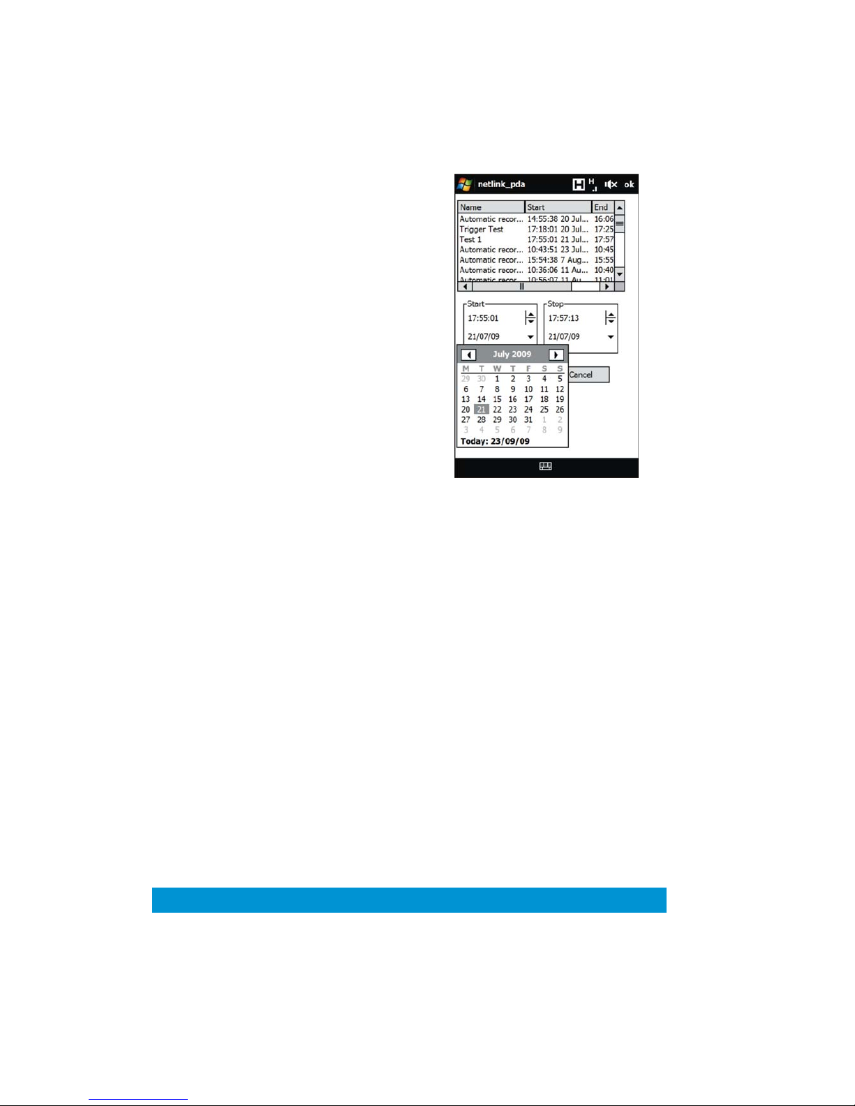
77
Retrieving Stored Content
To retrieve a recording stored on a NetLink hard disk:
1) Login to the NetLink.
2) Tap the connection icon and
then tap Play content >
Stored content.
3) A window like the one
shown here will appear,
showing content stored on
the NetLink unit’s hard disk.
The window shows the title of each recording, along beginning and
ending times and dates for each recording.
The user can select a recording, and then specify the exact portion of
that recording which they wish to download.
The start and stop points for the download can be adjusted using the
controls within the Start and Stop boxes.
The hours, minutes and seconds can be individually adjusted by
selecting
them and using the up/down arrows, or by selecting them and
typing the new value.
The dates can be adjusted by tapping the arrow, and selecting the new
date from the calendar that appears.
Once the desired start and stop points are selected, tap OK, and the
application will begin the download.
When the download is complete a window will appear playing back the
retrieved recording.
The playback can be con
trolled using the buttons below the playback
window. These controls are described in detail in section 9.7 of this
manual.

78
11 Technical Reference
11.1 NetLink Unit Connector pin-outs
Power - 4-pin 0B LEMO Socket
Pin No
Function
1
12 V
2
12 V
3
GND
4
GND
RS232 Control / PTZ / Data - 3-pin 0B LEMO Socket
Pin No
Function
1
TX
2
RX
3
GND
Triggers - 6-pin 1B LEMO Socket
Pin No
Function
1
Input 1
2
Input 2
3
GND
4
Input 3
5
Trigger output (held high as a 3V3 reference)
6
GND

79
Chaining (Input slot 1) - 6-pin 1B LEMO Socket
Pin No
Function
1
Chaining Clock Input
2
Chaining Data Input
3
GND
4
RS232 TX
5
RS232 RX
6
GND
A/V In (Input slot 2) - 5-pin 0B LEMO Socket – 2 key
Pin No
Function
1
Audio Right Input
2
Audio Left Input
3
GND
4
Composite Input
5
GND
A/V Out (Monitoring output) - 5-pin 0B LEMO Socket – 1 key
Pin No
Function
1
Audio Right Output
2
Audio Left Output
3
GND
4
Composite Output
5
GND

80
11.2 Triggers Cable
The triggers cable contains specially colour coded wiring which matches
the pin numbers as in the resistor colour code.
Connector Pin
Wire Colour
Signal
1
Brown
Trigger input 1
2
Red
Trigger input 2
3
Orange
Ground
4
Yellow
Trigger input 3
5
Green
Trigger out /3V3
reference
6
Blue
Ground
The correlation between wire colour and signal is shown in the table
above. The trigger activation for triggered recordings are made by the
use of a switch (or relay within a sensor) using a Pull Up Resistor (4K7
recommended) which grounds the output 3V3 supply in the event of an
activated trigger on one or more of the four input pins.
The switch/relay in the diagram below can be part of a PIR or other
sensor. The circuit shown corresponds to one of the trigger inputs, in
this case shown on Pin 1, though any of the three inputs can be used,
for example on multiple PIRs.
In the event that the Trigger function is enabled in the NetLink Player
application but the Trigger Cable is not connected, the behaviour of the
NetLink unit will be unpredictable as the inputs will ‘float’ causing the
recording state to be random.

81
12 Setting up A Server Based 3G NetLink System
12.1 Introduction
It is recommended that a NetLink system’s settings are never changed
from the factory setup. However, should they be changed for any
reason, causing the system to stop working, this section explains how to
restore the system to working order.
A typical server based 3G NetLink system is shown in the diagram
below.
The system is made up of three parts:
1) The data source, i.e. the NetLink box and its 3G modem.
2) The server and its ADSL modem.
3) The users’ computers and their internet connections.
The three parts of the system are typically at different locations, and
they talk to each other via the internet.
This section of the manual describes how to individually set up the three
parts of the system so they all
communicate with each other.
12.2 Setting up the NetLink and its 3G Modem
NetLink Set up
For this part of the setup, the NetLink unit’s Ethernet port is
disconnected from the modem and connected to a PC or laptop.
The NetLink unit’s control port should be connected to the computer’s
serial port.
• Using the serial port interface, set the NetLink IP address to
192.168.1.101.
• Still using the serial port interface set the NetLink mode to
Public Network Server m
ode. The NetLink will reboot.
• Set the PC or laptop IP address to 192.168.1.102.

82
• Start the NETEPLAY application on the computer that is
connected to the NetLink, and log in as supervisor.
• Right click the connection icon and select Advanced > IP
Parameters.
• The parameters should be set up as follows:
o DHCP: Off
o IP Address: 192.168.1.101
o Address mask: 255.255.255.0
o Default gateway: 192.168.1.1
o DNS server 1: Blank
o DNS server 2: Blank
o Dynamic DNS: Off
o The other parameters can b
e left as they are.
• Click Apply. The application will ask if it should attempt to reconnect using the new parameters. Click Yes and wait for the
application to re-connect.
• Once the application has re-connected, dismiss the IP
parameters window. Should the application fail to automatically
re-connect, login manually using the IP address that was set up
in the previous steps.
• Right click the connect
ion icon and select Advanced >
Change unit mode.
• Set New mode to Public network client.
• Set the Server address to the external IP address of the
NetLink server PC, i.e. its internet address.
• Click OK. The unit will automatically reboot in client mode and
the application will automatically log out.
This completes the NetLink unit setup. Unplug the NetLink power
supply and disconnect it from the computer.
3G Modem / Router set up
The set up details depend on which modem is used; therefore generic
instructions will be given.
• The 3G router’s local IP address should be s
et to 192.168.1.1.
• If a DHCP range is used, this should be from 192.168.1.2 to
192.168.1.100. This is to avoid clashes with the NetLink fixed
IP address.
• Network Address Translation (NAT) should be set up in the
router as follows:
o Ports 10000 to 10005 should be redirected to IP
address 192.168.1.101.
• If applicable, the 3G connection should be set up to be
constantly active.

83
12.3 Setting up the Server and its ADSL modem
Server PC Setup
The server PC should be set up as follows:
• IP address: 192.168.2.11 (or DHCP enabled, see below)
• Address mask: 255.255.255.0 (or DHCP enabled, see below)
• Default gateway: 192.168.2.1 (or DHCP enabled, see below)
ADSL Router Setup
• The ADSL router’s external IP address must be fixed.
• The ADSL router’s local IP address should be 192.168.2.1.
• If DHCP is used, the server PC should be set up to use DHCP
as well.
Also, the address 192.168.2.11 should be reserved for
the MAC address of the server PC.
• The modem/router should have Network Address Translation
(NAT) setup so that ports 10000 to 10005 are redirected to IP
address 192.168.2.11.
• If applicable, the modem should be setup to have its internet
connection enabled at all times.
12.4 Setting up the NETEPLAY Application
The NETEPLAY application must in the correct mode to work with this
type of N
etLink system. To set up the application:
In the top menu, select Options > Connection options. The
connection option window will pop up:
• Set Current mode to Fixed server.
• Set the Server address to the external IP address of the server
PC.
• Click Apply and OK.
Use the application as detailed in this manual.

84
Cobham Surveillance
Domo Products
11 Manor Court, Barnes Wallis Road, Segensworth,
Hampshire, PO15 5TH, England
T: +44 (0)1489 566 750
F: +44 (0)1489 880 538
 Loading...