

Page 1
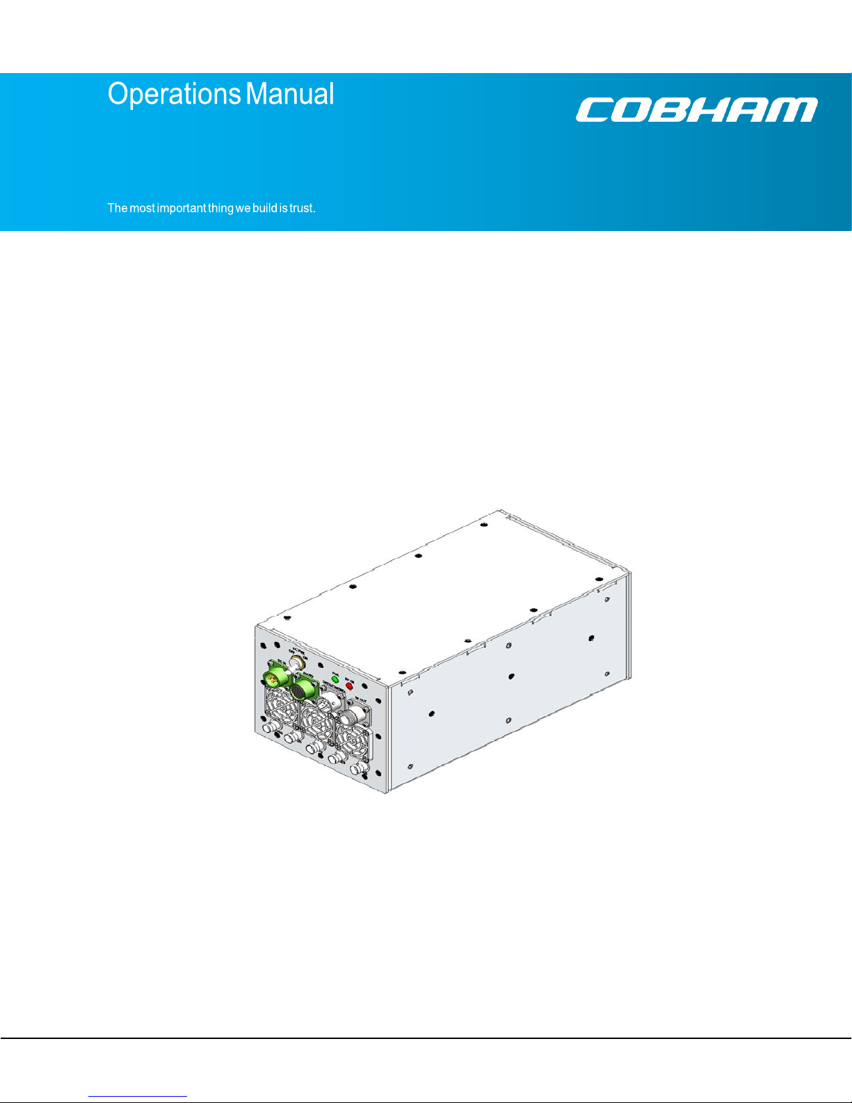
Messenger 2 Enhanced Compact High-Power Transmitter
(M2ECHPT)
Includes VEPA or Standard Power Amplifier
OPERATIONS MANUAL
100-M0177X1
GMS Inc. doing business as Cobham Tactical Communications and Surveillance
1 of 40
Cobham Tactical Communications and Surveillance
1916 Palomar Oaks Way, Suite 100, Carlsbad, CA 92008
Tel: 760-496-0055
FAX: 760-496-0057
www.cobham.com/tcs
Page 2

100-M0177X1
2 of 40
GMS Inc. doing business as Cobham Tactical Communications and Surveillance
www.cobham.com/tcs
Table of Contents
1.
Important Warning and General Safety Information ............................................................... 5
Acronyms ....................................................................................................................................... 7
2.
Introduction ................................................................................................................................ 8
2.1
About the Manual ......................................................................................................... 8
2.2
Warranty ...................................................................................................................... 8
2.3
Safe Operating Procedures ......................................................................................... 8
3.
General System Information ..................................................................................................... 9
3.1
Overview ..................................................................................................................... 9
3.2
Applications ................................................................................................................. 9
3.3
Key System Features ............................................................................................................ 9
3.4
Theory of Operation ................................ ................................ ................................ ... 10
3.5
Power Amplifiers (Standard or VEPA) ........................................................................ 13
3.6
Included Items ........................................................................................................... 13
4.
Hardware Overview .................................................................................................................. 14
4.1
Front Panel ................................................................................................................ 14
4.2
Rear Panel........................................................................................................................... 15
4.3
M2ECHPT Connectors .............................................................................................. 15
4.3.1
RF Output. ................................................................................................................................. 15
4.3.2
DC IN ............................................................................................................................... 16
4.3.3
DATA/CONTROL ...................................................................................................................... 16
4.3.4
Audio ............................................................................................................................... 17
4.3.5
Video1/Video 2 (SDI input, Composite input & ASI input) ................................................... 17
4.3.6
ASI OUT............................................................................................................................... 17
4.3.7
KLV TIME SYNC IN. ...................................................................................................................... 18
5.
Software Overview ................................................................................................................... 19
5.1
Product Control & Status Monitoring Approach .......................................................... 19
5.2
System Requirements ............................................................................................... 19
5.3
Connection ................................................................................................................ 19
6.
Initial Check Out ....................................................................................................................... 24
6.1
Getting Started .......................................................................................................... 24
7.
Specifications ........................................................................................................................... 26
Page 3

100-M0177X1
3 of 40
GMS Inc. doing business as Cobham Tactical Communications and Surveillance
www.cobham.com/tcs
List of Tables
Table 1 DC IN .............................................................................................................................................
16
Table 2 DATA/CONTROL ............................................................................................................................................. 16
Table 3 Audio Connections ...............................................................................................................................
List of Figures
Figure 1 M2ECHPT Link ............................................................................................................................ 11
17
Figure 2 Content Collection Format ................................................................................................ . 12
Figure 3 M2ECHPT Front View ...................................................................................................... 14
Figure 4 Rear Panel Connectors ..................................................................................................... 15
Figure 6 Welcome Page .................................................................................................................. 20
Figure 7 Windows Security Login .................................................................................................... 20
Figure 8 MAIN Page – LAN Interface ............................................................................................... 21
Figure 9 Configuration Groups Menu ............................................................................................... 22
Figure 10 High Power Link Setup .................................................................................................... 25
Figure 11 Interfacing PC to M2ECHPT ............................................................................................ 32
Figure 12 Window’s Start Button ......................................................................................................... 33
Figure 13 Control Panel w/Network & Internet Category .................................................................. 34
Figure 14 Network Adapter Settings ................................................................................................ 35
Figure 15 Local Area Connection Icon ............................................................................................. 36
Figure 16 Internet Protocol Version 4 .............................................................................................. 37
Figure 17 IP Address Setup ....................................................................................................................... 38
Figure 18 Entering a Static IP addresss ........................................................................................... 39
List of Appendices
Appendix A - IP Static Addressing and Interfacing to a Personal Computer .....................................................
A.1.
Static Addressing ................................................................................................................................
A.2.
DHCP (Dynamic Host Configuration Protocol) ..........................................................................
32
32
40
Page 4

GMS Inc. doing business as Cobham Tactical Communications and Surveillance
www.cobham.com/tcs
Revision
Date
Main Changes from Previous version
Edited by
Checked
X1
29 June 2012
Initial Release
T.G.
Revision History
100-M0177X1
4 of 40
Page 5

GMS Inc. doing business as Cobham Tactical Communications and Surveillance
www.cobham.com/tcs
1. Important Warning and General Safety Information
The following information is presented to the operator to ensure awareness of potential harmful RF
(radio frequency)
exposure
and general hazards. With regards to potential harmful RF electromagnetic
fields the text below is only a brief summary highlighting the possible risks and how to minimize exposure.
The summary is based on OET Bulletin 65 “Evaluating Compliance with FCC Guidelines for Human Exposure
to Radiofrequency Electromagnetic Fields”
before operating the equipment and for additional in depth information refer to OET Bulletin 65.
(1)
. The user should carefully read and comprehend the following
1.
FCC has set guidelines
(1)
for evaluating exposure to RF emissions that the user must be aware of
when operating the microwave transmitter. The maximum power density allowed at 1500–
100,000 MHz is 5mW/cm2 for occupational/controlled exposure* and 1mW/cm2 for general
population/uncontrolled exposure**. These are the limits for maximum permissible exposure (MPE)
as called out in the FCC guidelines (for the above mentioned frequencies).
2.
Exposure is based upon the average time spent within the RF field with a given intensity (field units
in mW/cm2). Hence it may be controlled (or at least minimized) by observing the safe distances
and time exposed. Safe distances are calculated from equations predicting RF Fields
3.
The transmitter is capable of harmful radiation if safe operating practices are not observed.
(3)
.
*”Occupational/controlled exposure limits apply to situations in which persons are exposed as a consequence of
their employment and in which those persons who are exposed have been made fully aware of the potential for
exposure and can exercise control over their exposure. Occupational/controlled exposure limits also apply where
exposure is of a transient nature as a result of incidental passage through a location where exposure levels may be
above general population/uncontrolled limits (see below), as long as the exposed person has been made fully aware
of the potential for exposure and can exercise control over his or her exposure by leaving the area or by some other
appropriate means……..”
** “General population/uncontrolled exposure limits apply to situations in which the general public may be exposed
or in which persons who are exposed as a consequence of their employment may not be made fully aware of the
potential for exposure or cannot exercise control over their exposure. Therefore, members of the general public
would always be considered under this category when exposure is not employment-related, for example, in the case
of a telecommunications tower that exposes persons in a nearby residential area.“
(1)
OET Bulletin 65, Appendix A Table 1 Limits for MPE
http://www.fcc.gov/Bureaus/Engineering_Technology/Documents/bulletins/oet65/oet65.pdf
(2)
OET Bulletin 65, page 9, definitions of types of exposure
http://www.fcc.gov/Bureaus/Engineering_Technology/Documents/bulletins/oet65/oet65.pdf
(3)
OET Bulletin 65, page 19, Equations for predicting RF Fields
http://www.fcc.gov/Bureaus/Engineering_Technology/Documents/bulletins/oet65/oet65.pdf
4.
Antenna minimum safe operating distance is 20cm (8 inches). It is the responsibility of the
(2)
(2)
qualified end-user of this intentional radiator to control the safe distances and exposure limits to
bystanders.
5.
Do not substitute any antenna for the one supplied or recommended by the manufacturer. The
installer is responsible for ensuring that the proper antenna is installed.
6.
It should be noted that this device is an intentional radiator, hence:
100-M0177X1
5 of 40
Page 6

GMS Inc. doing business as Cobham Tactical Communications and Surveillance
www.cobham.com/tcs
Changes or modifications not expressly approved by the party responsible for
compliance could void the user’s authority to operate the equipment.
NOTE: The manufacturer is not responsible for any radio or TV interference caused by
unauthorized modifications to this equipment. Such modifications could void the
user’s authority to operate the equipment.
7.
DC power to the unit should never be applied until the antenna (or other suitable load) has been
attached to the RF output connector. Safe operating procedures must be observed when unit is
transmitting into an antenna (see sections 1 &2 above).
8.
Electro-Static Discharge (ESD) precautions should be observed as a safe practice.
9.
The transmitter will generate considerable heat and is the responsibility of the end user to properly
heat sink the device before using.
100-M0177X1
6 of 40
Page 7

GMS Inc. doing business as Cobham Tactical Communications and Surveillance
www.cobham.com/tcs
Acronyms
Name
Meaning
16 QAM
16-state Quadrature Amplitude Modulation
64 QAM
64-state Quadrature Amplitude Modulation
A/V
Audio/Video
AES
Advanced Encryption System (32 bit)
ASI
Asynchronous Serial Interface
BDC or BDCC
Block down converter
COFDM
Coded Orthogonal Frequency Division Multiplexing
CVBS/Y
Composite video/Luminance with S-video
C Chroma video
D/C
Down-Converter
FEC
Forward Error Correction
GUI
Graphical User Interface
HD High Definition
I/O
Input/ Output
Kbaud
Kilobaud per second
Kbps
Kilobits per second
Mbps
Megabits per second
MER
Modulation Error Rate
MPEG
Moving Picture Experts Group
MSR
Messenger Smart Receiver
M2D
Messenger Two Decoder
M2T
Messenger Two Transmitter
M2L
Messenger Two Link
NTSC
National Television System Committee
PAL
Phase Alternation Line
QPSK
Quadrature Phase Shift Keying
RF Radio Frequency
RX Receiver
S/N
Signal-to-Noise Ratio
THD
Total Harmonic Distortion
SD Standard Definition
SDI Serial Digital Interface
TX Transmitter
VDC
Volts (Direct Current)
VEPA
Very Efficient Power Amplifier
This section lists and describes the various acronyms used in this document.
100-M0177X1
7 of 40
Page 8

GMS Inc. doing business as Cobham Tactical Communications and Surveillance
www.cobham.com/tcs
2. Introduction
2.1
About the Manual
Cobham User Manuals focus on providing the end user an easy to understand operational instructions
to quickly setup and deploy the equipment. The Cobham Technical Operation Manuals focus on the
technical details and setup of the equipment. The Technical Manuals also provide a more in depth
explanation of the settings and specifications of the equipment that technicians can use to verify the
operational status.
2.2
Warranty
Cobham offers a 12 month standard product warranty. During this period, should the customer
encounter a fault with the equipment we recommend the following course of action:
Check the support section of the website for information on that product and any
software/firmware upgrades.
If fault persists call our support line and report the fault. If fault persists and you are informed to
return the product, please obtain an RMA number from the Cobham support department or
website and ship the equipment with the RMA number displayed and a description of the fault.
Please email the support section the airway bill/consignment number for tracking purposes.
Depending on the nature of the fault, Cobham strives to repair the equipment and return it to the
customer within 14 days of the item arriving at our workshops. Obviously it is impossible to
accommodate for all types of faults and to manage 100% replacement part availability; delays are
sometimes inevitable.
Please contact Cobham for details of packages that can be tailored to meet your individual needs,
whether they are service availability, technical training, local geographic support or dedicated spares
holdings.
2.3
Safe Operating Procedures
Ensure that the power supply arrangements are adequate to meet the requirements of
M2ECHPT product.
Operate within the environmental limits specified for the product. The transmitter will generate
considerable heat and it is the responsibility of the end user to properly heat sink the device
before using.
Electro-Static Discharge (ESD) precautions should be observed as a safe practice.
Only authorized, trained personnel should open the product. There are no functions that
required the User to gain access to the interior of the product.
100-M0177X1
8 of 40
Page 9

GMS Inc. doing business as Cobham Tactical Communications and Surveillance
www.cobham.com/tcs
3.
General System Information
3.1
Overview
The M2ECHPT is a second generation AVC HD/SD COFDM transmitter that combines all the features
and capabilities of Cobham Surveillance’s (CS’s) Messsenger 2 AVC HD/SD Transmitter with the
additional features listed in the Key System Features section below. Key features include optional Dual
Audio/Video/Data processing with end to end system-level latencies of down to~44mS when used with
CS Receiver/Decoders.
The Ultra-low system latency greatly enhances real-time operating when the link is used in time critical
situations like piloting Unmanned Aerial Vehicles (UAVs) or Unmanned Ground Vehicles (UGVs) or in
threat response. Optional Dual video processing enables 3D content collection which provides depth
perception and greater control for UGV applications requiring fine spatial operations like explosive
device de-arming. The M2ECHPT’s 3D capability also enhances Entertainment, Sports, and ENG
applications.
The M2ECHPT can optionally provide time-correlated KLV-1 and KLV-2 META data processing1 that is
used in Airborne Surveillance Applications and Geospatial determination. The META data can be
extracted from the SDI/HD-SDI video’s ancillary data space or input on a separate RS-422 interface.
3.2
Applications
The M2ECHPT Transmitters can be used in the following environments:
Helicopter Links
UAV/UGV Applications
Audio/Video Surveillance
Airborne/Ground Surveillance
3.3
Key System Features
Up to 15W Linearized Output Power
AVC HD/SD Encoder (up to 1080p 30FPS)
Supports Dual Audio/Video/Data programs
o Multi-Camera Support
o 3D Support
o Dual 3Gbps HD-SD/SDI and Analog SD Video Input Interfaces Option
Robust Link Performance with COFDM Modulation (DVB-T 2K or 4K3 carriers)
Bandwidths DVB-T 6,7, & 8 MHz (STD) & 12, 14 & 16 MHz (4K3)
Dual L/S Band Capability
No External Heat Sink Required
Output Frequency: 0.9 to 7 GHz (In-Bands)
Low System Latency (~44mS)
4,5
Secure Scrambling Encryption Option (128/256-bit AES-C)
100-
M0177X1
9 of 40
Page 10

GMS Inc. doing business as Cobham Tactical Communications and Surveillance
www.cobham.com/tcs
Analog and Embedded Audio
Transport Stream Steaming via LAN or ASI or Serial Interface
User Data Option
Control via LAN Web Server or Serial Interface
+12Vdc or +28Vdc Option
Companion COFDM Receiver with Post-Detect Diversity Reception
3.4
Theory of Operation
The M2ECHPT Series “Messenger Two Series” product line incorporated AVC/H.264 compression
technology with ultra-low delay that covers all the SD and HD formats up to 1080p. AVC compression
provides dramatically increased compression efficiency over MPEG-2 which allows our link to provide
superior coverage over a wider operating range!
There are two core hardware configurations for M2ECHPT. The SD/HD-SDI configuration accepts up to
two Standard Definition (SD) or High Definition (HD) 4:2:2 Digital Video (SD/HD SDI) or analog
composite Video and Analog Stereo Audio Inputs (Mic or Line Level) and Embedded Audio (up to a
total of two stereo pairs or four mono channels) set or programs. Mic bias is also provided. In the
HDMI configuration
*P4
, the SDI/HD-SDI interfaces are replaced with two HDMI interfaces that accept
both digital video and audio. Dual SD Composite Video inputs are also provided with the HDMI
configuration
Both Video programs can be compressed according to the Advanced Video Compression (AVC)/H.264
(HD/SD) specification with the same or different frame resolutions, rates and formats. The low-latency
AVC Encoder supports the Baseline Profile with extensions with resolutions from 480 to 1080 with
support for either interlaced or progressive formats. The Audio is compressed using MPEG-1 Layer 2
compression. Low rate user data up to 115KBaud can be optionally supported. Both programs, Audio,
Video and User Data Packets PES Streams are multiplexed with Basic Service Data to indicate their
respective Service Names. If two programs are active, the two transport steams are multiplexed into a
single multi-program stream. The stream can be optionally scrambled with AES scrambling system to
provide protection in sensitive applications. User selections for all transport stream ID numbers and
service names are provided.
The M2EPHT is a complete system with Audio/Video encoders/compressors and all the required
processing to transmit the modulated signal with up to 15W (band dependent). CS’ COFDM wireless
equipment provides a standard robust digital modulation system known as Coded Orthogonal
Frequency Division Multiplexed (COFDM) that provides frequency diversity and powerful Forward Error
Correction (FEC) algorithms. This modulation is ideal for transmitting over water or into urban
environments which typically have high multi-path interference.
Our Messenger Receivers include an option for Spatial Maximal Ratio Pre-Detect Diversity to combat
multipath reflections found in indoor/urban environments. Cobham’s Messenger six or eight channel
receivers with associated Messenger Antenna Arrays (MAAs) provide wide reception range without the
hassle and cost of an auto tracking antenna system. The Messenger series Tx/Rx products provide a
robust wireless link that is effective against the multipath interference experienced by analog systems
and provides reliable data transmission in the most difficult of terrains.
100-M0177X1
10 of 40
Page 11
GMS Inc. doing business as Cobham Tactical Communications and Surveillance
www.cobham.com/tcs
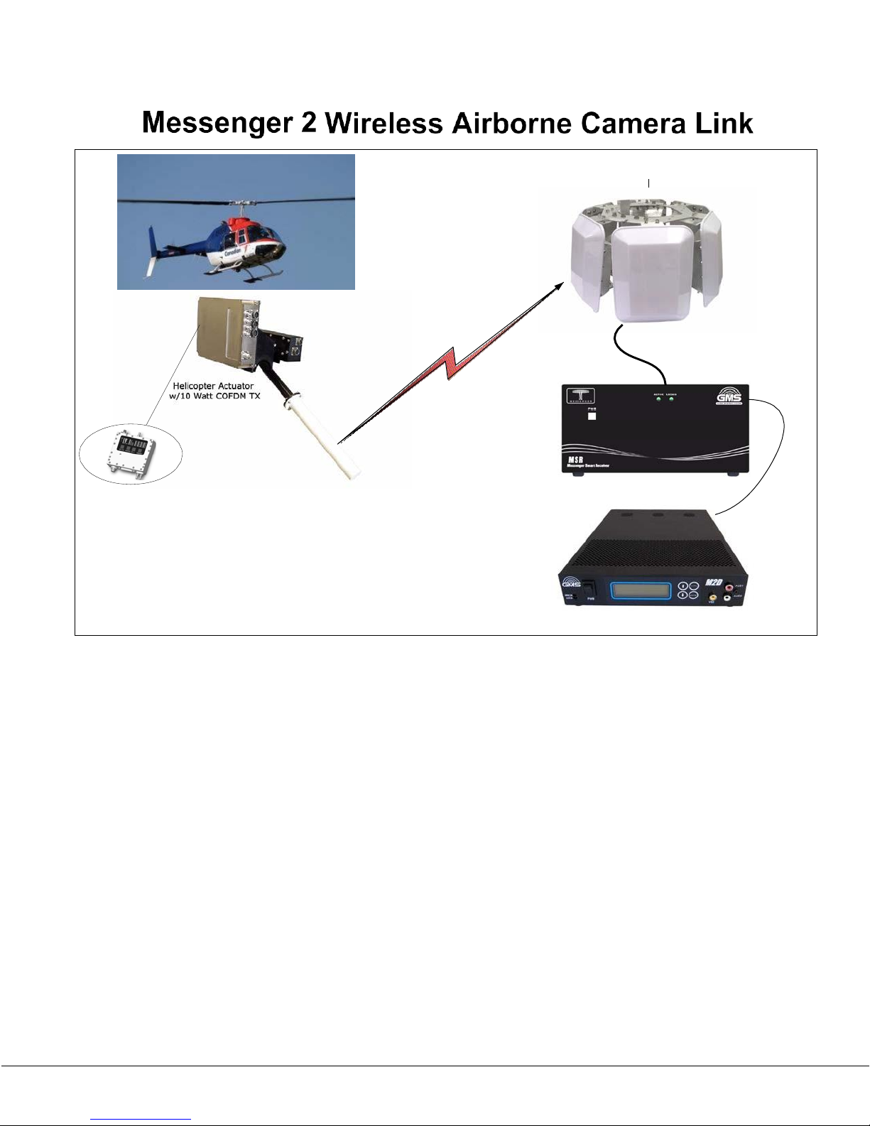
Messenger Antenna Array
Messenger Smart Receiver
M2TE inside 10W Tx
Messenger 2 AVC HD/SD Decoder
Figure 1 M2ECHPT Link
In 2K Mode the M2ECHPT uses standard DVB-T coding and modulation. DVB-T stands for Digital Video
Broadcasting — Terrestrial; it is the DVB European-based consortium standard for the broadcast
transmission of digital terrestrial television that was first broadcast in the UK in 1997. This system
transmits compressed digital audio, video and other data in an MPEG transport stream, using coded
orthogonal frequency-division multiplexing (COFDM or OFDM) modulation.
The OFDM scheme works by splitting the digital data stream into a large number of slower digital
streams each of which digitally modulate a set of closely spaced adjacent carrier frequencies. COFDM
goes a step further by using a “Coding” scheme to map the data onto the multiple carriers in a way that
maximizes recovery from link errors. This coding includes Forward Error Correction with Convolution
Interleaves’ and Reed Solomon encoding along with careful distribution of the data onto the multiple
carriers. COBHAM has chosen to use 2K carrier in which 1,705 carriers actually carry the payload that
are approximately 4KHz apart. DVB-T offers three different modulation schemes (QPSK, 16QAM,
64QAM).
100-M0177X1
11 of 40
Page 12

GMS Inc. doing business as Cobham Tactical Communications and Surveillance
www.cobham.com/tcs
4K Carrier Mode
The 4K HIGH-THROUGHPUT OPTION enables user-selectable options to set bandwidths from 6 MHz to
16 MHz and to double the throughput of our standard M2T (Up to 63 Mbps!). In 2K carrier mode the
system would need to operate in 64-QAM to support dual program/video operations. Using 4K carriers
and the 16 MHz bandwidth, the link can support dual program/video HD operation using 16 QAM. This
increases link robustness and provides an additional 13.5 dB of gain with a link margin increase greater
than 4.7 x in operating range! for the same throughput rate in a standard HD MPEG-2 DVB-T system!
With the 4 K HIGH-THROUGHPUT OPTION you can run with fully DVB-T compliant 2K carriers and
bandwidths of 6, 7, or 8 MHz. When you switch to 4K carriers you can select 12, 14 or 16 MHz
bandwidth.
LAN/IP Port
The M2ECHPT contain a 10/100BaseT LAN interface that can be used both for Control & Status
monitoring and for Transport Stream (TS) streaming in and out of the device. The IP address can be
assigned automatically via a DHCP server or assigned a Static IP address. Control & Status monitoring is
accomplished via a WEB browser application. TSs can be sent out or in via UDP/IP or RTP/UDP/IP
transfer protocols.
3D Support
3D is a very new area in the Broadcast industry. From a content collection standpoint it is normally
accomplished with two separate cameras that are GEN-LOCKED together outputting two separate
Video signals.
Figure 2 Content Collection Format
AES-C Scrambling
The AES-C Scrambling option can be used to add security to your data transmission. The system
scrambles the payload portion of the TS packets. Only the TS header remains unscrambled to
enable operation with standard DVB-T receivers. The 128 bit-scrambling key is entered through the
M2ECHPT’s control interface. The user can enable or disable the scrambling as well as choosing if
the key is stored within the Tx or not via Cobham’s LAN WEB Page GUI. Encryption on/off is also
available from the local control panel.
100-M0177X1
12 of 40
Page 13

GMS Inc. doing business as Cobham Tactical Communications and Surveillance
www.cobham.com/tcs
3.5
Power Amplifiers (Standard or VEPA)
The M2ECHPT comes with either the VEPA or the Standard power amplifier. The VEPA (Very Efficient
Power Amplifier) is Cobham/GMS’ newest design specifically targeted for COFDM modulation formats
because of its high linearity and efficiency. Most of the connections using either the VEPA or the
Standard PA are the same. Where there are differences they are pointed out in the manual. In
addition if there are differences in specifications they are also noted.
3.6
Included Items
NOTE: Based on customer application Cobham may deliver a receiving system, additional cables and
antennas. Contact Cobham for further information.
The device is pre-configured by Cobham prior to shipment (based on customer requirements), thus is
ready to work “right out of the box”.
100-M0177X1
13 of 40
Page 14

GMS Inc. doing business as Cobham Tactical Communications and Surveillance
www.cobham.com/tcs
4.
Hardware Overview
The basic M2ECHPT transmitter hardware configuration is outlined in this section:
4.1
Front Panel
The front panel consists of 3 fans designed to cool the unit.
Figure 3 M2ECHPT Front View
100-M0177X1
14 of 40
Page 15

GMS Inc. doing business as Cobham Tactical Communications and Surveillance
www.cobham.com/tcs
4.2
Rear Panel
The rear panel is shown in Figure 4 below. The connector types and pin outs are discussed in the
following section.
Figure 4 Rear Panel Connectors
4.3
M2ECHPT Connectors
Note: The only difference between the VEPA and Standard power amplifier is that the “RF ON” LED
indicator is not used with the VEPA power amplifier. All other connections are the same.
4.3.1
RF Output
The M2ECHPT uses a female “N” type bulkhead connector for its “RF OUTPUT” port.
Note: Transmitters should not be powered on without a load. Doing so could cause
damage to the output PA. A proper heat sink is also required.
100-M0177X1
15 of 40
Page 16

GMS Inc. doing business as Cobham Tactical Communications and Surveillance
www.cobham.com/tcs
4.3.2
Connector Name
Connector Type
Pin
Function
DC In
PTO-4
A +VDC
DC In
PTO-4
B +VDC
DC In
PTO-4
C GND
DC In
PTO-4
D GND
Connector Name
Connector Type
Pin
Function
Data/Control
PTO-19
A GND
Data/Control
PTO-19
B RS-232 DATA RX1
Data/Control
PTO-19
C RS-232 DATA TX1
Data/Control
PTO-19
D RS-232 DATA RX2
Data/Control
PTO-19
E RS-232 DATA TX2
Data/Control
PTO-19
F RS-422_A P
Data/Control
PTO-19
G RS-422_A N
Data/Control
PTO-19
H GND
Data/Control
PTO-19
J RS-422_B P
Data/Control
PTO-19
K RS-422_B N
Data/Control
PTO-19
L Conditioned DC +
Data/Control
PTO-19
M Conditioned DC -
Data/Control
PTO-19
N RESET
Data/Control
PTO-19
P FPGA GPIO 0
Data/Control
PTO-19
R GND
Data/Control
PTO-19
S ENET RD P
DC IN
Connector Type: 4 pin PTO, Male.
The M2ECHPT accepts +12dc or +28Vdc input power (depending on configuration). GMS cable
(780-C0219) is used to connect to the DC IN connector. See drawing 100-C0219 for power
connections (Appendix B).
Pin outs for this connector are shown in the table below.
4.3.3
DATA/CONTROL
Connector Type: 19 pin PTO, Male
Table 1 DC IN
The Data/Control brings out various input-output connections such as Ethernet/LAN connections,
RS-232 Data/TX/Rx connections, RS-422 connections, etc. (see table below).
Pin outs for the connector are shown in the table below.
Table 2 DATA/CONTROL
100-M0177X1
16 of 40
Page 17

GMS Inc. doing business as Cobham Tactical Communications and Surveillance
www.cobham.com/tcs
Data/Control
PTO-19
T ENET RD N
Data/Control
PTO-19
U ENET TD P
Data/Control
PTO-19
V ENET TD N
Connector Name
Connector Type
Pin
Connection
PWR Detect/Audio
PTO-10
A Audio1 Diff P
PWR Detect/Audio
PTO-10
B Audio Gnd
PWR Detect/Audio
PTO-10
C Audio1 Diff N
PWR Detect/Audio
PTO-10
D Audio Gnd
PWR Detect/Audio
PTO-10
E Audio1 Bias
PWR Detect/Audio
PTO-10
F Audio2 Bias
PWR Detect/Audio
PTO-10
G Audio2 Diff P
PWR Detect/Audio
PTO-10
H Audio Gnd
PWR Detect/Audio
PTO-10
J Audio2 Diff N
PWR Detect/Audio
PTO-10
K Audio Gnd
4.3.4
Audio
Connector Type: 10 pin PTO, Female
Pin outs for this connector are shown in the table below. Audio inputs can be configured as single
ended (Mic or Line level) or differential. Various configurations are available depending on the
wiring of the connections and the software setup of the audio selections. Consult factory for premade audio cables.
4.3.5
Video1/Video 2 (SDI input, Composite input & ASI input)
Table 3 PWR DETECT /Audio Connections
Connector Type: BNC-F 75 ohm
The two video connectors provide an input for SD/HD-SDI video streams, Composite video
streams or can be used an input for
are by default able to handle an SD/HD-SDI or Composite input. However if using an ASI input the
transmitter needs to be switched from a SDI input (or Composite input) to an ASI input mode. This
is done using the LAN WEB based GUI control software (see software overview section
Reference source not found.
1.485 Gbps for High Definition. When using the input as an ASI input ensure the transmitter
channel rate is set approximately 10% higher than the ASI stream rate coming into the transmitter.
4.3.6
ASI OUT
Connector Type: BNC-F, 75 ohm
This connector provides an output for DVB-ASI Transport Streams. The output bit rate is 270
Mbps. The Transport Stream does not include the SI table, User-Data or AES encryption which is
added later in the processng chain.
100-M0177X1
ASI
DVB compliant Transport Streams. The video connectors
Error!
.1). The SDI input bit rate is 270 Mbps for Standard Definition and
17 of 40
Page 18

GMS Inc. doing business as Cobham Tactical Communications and Surveillance
www.cobham.com/tcs
It can be useful as a monitoring/troubleshooting tool or as a standalone DVB- ASI Transport Stream
output with rates up to 50 Mbps.
As a monitoring/troubleshooting tool the user can verify the correct operation of the encoder –
decoder portion of the link by running this output directly into the decoder’s ASI INPUT, essentially
bypassing the RF portion of the link.
As a standalone Transport Stream output the encoder can be placed into a “Encoder” only mode in
which the ASI Transport Stream rates can run as high as 50 Mbps (see software section 5.1).
*P5
4.3.7
KLV TIME SYNC IN
Connector Type: BNC-F, 75 ohm
This input is used to provide time-correlated KLV-1 and KLV-2 META data processing that is used in
Airborne Surveillance Applications and Geospatial determination.
100-M0177X1
18 of 40
Page 19

GMS Inc. doing business as Cobham Tactical Communications and Surveillance
www.cobham.com/tcs
5.
Software Overview
5.1
Product Control & Status Monitoring Approach
Cobham transmitters provide programmable presets or set-up groups that can be configured through a
WEB-based control and status interface that launches through the LAN interface from the transmitter.
Set-up “Groups” are selected through the WEB-based interface. The M2ECHPT allows 20 set-up groups.
This section briefly touches on the WEB-based control. For detailed operation the user should refer to
the 100-M0171 “Messenger 2 Transmitter Enhanced” Operations Manual which can be found
on-line at
http://www.cobham.com/about-cobham/aerospace-and-security/about-us/tactical-communicationsand-surveillance/carlsbad/products/cofdm-transmitters/M2ECHPT.aspx
5.2
System Requirements
The WEB Control and Status interface can be launched from several WEB Explorer interfaces such as
Microsoft’s Internet Explorer, Mozilla’s FireFox, and Google’s Chrome.
The WEB interface requires the WEB browsers to support JavaScript. The WEB interface has been
tested with Windows Internet Explorer 8, Firefox 8.0 and some versions of Google Chrome.
5.3
Connection
The IP address of the transmitter must be known before launching an internet browser. The
M2ECHPT’s are shipped out with a static IP address of
192.168.1.36.
The M2ECHPT only supports
IPv4 addressing. Using this address and an internet browser the user can access the internal
M2ECHPT’s WEB server.
Using a PC open an internet browser and type the IP address (
the internet WEB browser (also reference Appendix A which goes into more detail regarding IP static
addressing and interfacing to a personal computer). The welcome page opens, see Figure 5. Click on
the
CONTINUE
and PASSWORD; the defaults are “
button. A login prompt window opens as shown in Figure 6. Type in the USER NAME
admin
”, “
admin
”. The main menu window opens. See Figure 7
192.168.1.36
) into the address bar of
below.
100-M0177X1
19 of 40
Page 20

GMS Inc. doing business as Cobham Tactical Communications and Surveillance
www.cobham.com/tcs
Figure 5 Welcome Page
Figure 6 Windows Security Login
100-M0177X1
20 of 40
Page 21

GMS Inc. doing business as Cobham Tactical Communications and Surveillance
www.cobham.com/tcs
Figure 7 MAIN Page – LAN Interface
100-M0177X1
21 of 40
Page 22

GMS Inc. doing business as Cobham Tactical Communications and Surveillance
www.cobham.com/tcs
From here, to the left of the screen are the available menus, Main, Configuration Groups, Status,
System Setup, Upgrade and Help. The Configuration Groups/Setup window is where the preset groups
can be selected. To select a different preset group use the
from 20 preset groups. Then click on the
LOAD
button to the right of the screen. There are 7 tabs (see
SELECT GROUP
pull down box and select
Figure 8 below). Changes to the preset groups, including any changes to the RF, Video, Audio, TS
(transport stream), Encrypt, Aux Data and Streaming can be done by selecting one of the seven tabs,
make the change to the corresponding text box (or pull down box), click on the APPLY button and then
the SAVE button if the change is to be permanent to the current group.
Figure 8 Configuration Groups Menu
100-
M0177X1
22 of 40
Page 23

GMS Inc. doing business as Cobham Tactical Communications and Surveillance
www.cobham.com/tcs
As stated above for detailed instructions on the use of the LAN interface refer to the online manual
100-
M0171. In short with this interface:
Preset groups (from 20 groups) can be selected
Individual group parameters can be changed
Groups can be exported, imported and restored (default groups)
New firmware updates can be loaded
Network configurations can be changed. DHCP or Static are available
Encryption setups are available
RF power attenuation levels are available
Serial port setup is available
A STATUS page which provides real time update is available
100-M0177X1
23 of 40
Page 24

GMS Inc. doing business as Cobham Tactical Communications and Surveillance
www.cobham.com/tcs
6. Initial Check Out
The standard M2ECHPT kit includes the following items:
M2ECHPT unit
M2ECHPT power cable (P/N 780-C0219)
Note: Based on customer application the factory may deliver additional cables and antennas.
Contact factory for further information.
The M2ECHPT is pre-configured by the factory prior to shipment (based on customer
requirements), this is ready to work right out of the box.
6.1
Getting Started
Prior to installing the M2ECHPT into the desired target environment, an initial checkout should be
performed to ensure proper operation of the unit. The initial checkout consists of configuring a basic
High Power Messenger Digital link (HP-MDL) check out.
Notes/Warnings:
o Transmitters should not be powered on without a load (antenna or proper 50 ohm load).
Doing so could cause irreversible damage to the equipment.
o In a lab environment a high power attenuator (30 dB, DC to 8.5GHz, 150Watts average is
recommended) should be installed at the RF output connector at all times to prevent
overloading (on the receiver side) and standing wave reflection damage to the transmitter.
o See DC power requirements under specifications for Power Supply requirments.
Figure 9 shows a basic interconnection configuration to establish a wireless High Power
Messenger Digital Link, noting that the receivers, down converters (d/c) and other additional
hardware is sold separately. The steps necessary to set up the configuration are described
below.
100-
M0177X1
24 of 40
Page 25

GMS Inc. doing business as Cobham Tactical Communications and Surveillance
www.cobham.com/tcs
Power Source
Video Source
D/C
Monitor
Figure 9 High Power Link Setup
Install omni-directional antennas onto the M2ECHPT RF output port and downconverter(s) (d/c)
RF(radio frequency) input port.
Attach the power cable (780-C0219) to the M2ECHPT.
Attach the RF cable from the downconverter IF (intermediate frequency) output port to the RF
IN port of the receiver.
Attach a video source to the M2ECHPT using the SDI input(s).
Attach a BNC cable from the BNC video output port (HD/SD-SDI out, component out or
composite out) of the receiver/decoder to a video monitor.
Apply power to all equipment. Also ensure power has been applied to the downconverter(s).
After approximately 20 seconds the link should be established and video provided by the
source should be displayed on the monitor. If a link is not established check to ensure power to
all devices has been applied and the transmitter and receiver have been tuned to the same RF
frequency.
100-M0177X1
25 of 40
Page 26

GMS Inc. doing business as Cobham Tactical Communications and Surveillance
www.cobham.com/tcs
7. Specifications
Format
Resolution @ Frame Rate
1080i
1080PsF
1920x1080@23.98/24/25/29.97/30 fps
1920x1080 @ 23.98/24/25/29.97/30 fps
1080p
1920x1080@23.98/24/25/29.97/30 fps
720p
1280x720 @ 50/59.94/60 fps
Format
Resolution @ Frame Rate (frames
per second)
576i
720x576 @ 25/29.97 fps (PAL)
480i
720x480 @ 25/29.97 fps (NTSC)
RF Output
Output Frequency:
C band 4910 to 4990 MHz
Frequency Resolution****: 100 KHz or 1 MHz
Frequency Accuracy: (+/-) 2.5 ppm (High-G Crystal Optional)
Bandwidth: Selectable
RF Output Power: up to 15W (model dependent)
Output Impedance: 50 Ohms with VSWR <1.5:1
Video Encoding (HD)
Video Processing Capability: Single Video input, Dual Video Inputs (processing of each input can be
independently set for all encoder parameters)
3D Modes: Content collection (Separate inputs from two cameras that are GENLOCK)
Interfaces: Dual HD-SDI/SDI or Dual HDMI (Option)
HD-SDI Standards: SMPTE-292M, -296M, -274M, -424M
HD-SDI SDI Connectors: 1.0/2.3 mm (75 Ohm) 3Gbps
Compression Standard: AVC / H.264
Motion Est. Range: (+/-) 192 Horiz., (+/-) 128 Vert.
6, 7, 8 MHz Standard
12, 14, 16 MHz Optional
(Per ISO/IEC 14496-10 with interlaced extensions)
Video formats/resolutions supported:
Variable GOP Structure: I-only and IP
PsF supported with INTERLACED FORMAT
Profiles supported: BP@HL with interlaced extensions
HDMI Version: Optional*
P3
**Video bit rates: HDTV to 50 Mbps
***System Latency: down to <44 mS (Ultra-Low Latency Mode)
Video Encoding (SD)
Video Processing Capability: Single Video input, Dual Video Inputs (processing of each input can be
independently set for all encoder parameters)
3D Modes: Content collection (Separate inputs from two cameras that are GENLOCK)
Interfaces: Dual SDI and Dual Composite or Dual HDMI and Dual Composite (Option)
SDI Standards: SMPTE-259M
SDI/ Composite Connector: 1.0/2.3 mm (75 Ohm) [Same as HD-SDI connector]
HDMI Version: Optional*
Compression Standard: AVC / H.264
(Per ISO/IEC 14496-10 with interlaced extensions)
Motion Est. Range: (+/-)192 Horiz., (+/-) 128 Vert.
Video format standards: NTSC or PAL
P3
100-M0177X1
26 of 40
Page 27

GMS Inc. doing business as Cobham Tactical Communications and Surveillance
www.cobham.com/tcs
Variable GOP Structure: I-only and IP
Profiles: BP@ML with interlaced extensions
**Video bit rates: to 25 Mbps
***System Latency: down to <44 mS (Ultra-Low Mode)
Audio Encoding
Analog Audio Inputs:
Qty 4 Total, Two Dual, Line-Level and Dual Mic-Level, Single-Ended or Differential, Clip Level 12 dB
Mic Bias: 5 V
Input Impedance: 100K Ohms
Standards: SMPTE-272M, -299M
Digital Audio: Dual Embedded (2-channel) per Video input
Embedded Audio Format: SMPTE 299M
Compression Standard: MPEG-1 Layer 2
Bit rates: 256 Kbit/s per channel.
Sampling Frequency: 48 KHz
THD: < 1 % max.
Response: 20 Hz to 12 KHz, (+/-) 0.25 dB
Crosstalk: >55 dB min
S/N: >50 dB RMS
Connector: P/O Multi-pin Connector
Transport Stream
Standard: per ISO/IEC 13818-1
Packet Size: 188 Byte
Format: AVC / H.264/ MPEG-4 Part 10 encapsulated into an MPEG Transport Stream
Specification: ITU-T Rec. H.222.0 Amendment 3
Bit Rate: Automatically set from active service settings.
ASI Output
Connector: 1.0/2.3 mm (75 Ohm)
Modulation
Modulation Type: COFDM w/QPSK, 16-QAM,
or 64-QAM
Standard: DVB-T compliant
FEC: 1/2, 2/3, 3/4, 7/8
Guard Intervals: 1/32, 1/16,1/8,1/4
COFDM Carriers: 2K Carriers
100-M0177X1
27 of 40
Page 28

GMS Inc. doing business as Cobham Tactical Communications and Surveillance
www.cobham.com/tcs
High Throughput Option
FEC: 1/2, 2/3, 3/4, 7/8
Guard Intervals: 1/32, 1/16, 1/8, 1/4
COFDM Carriers: 4K Carriers
Program Identification
The unit allows the user to set-up a unique Provider Name and Service Name for each active program.
Scrambling Option
Type: 128/256 Bit Advanced Encryption Standard (AES)
Key Storage: User Controlled, volatile or non-volatile
AUX Data Option
Protocol: RS-232C, Asynchronous, 8/7 Bits, No/Even/Odd-Parity, 1 Stop Bit
Data Rate: Selectable, Up to 115200 KBaud
Aux Data PID: Selectable
Connector: P/O Multipin Connector
Video Adjustments
The digital Video processing provides adjustment for; Brightness, Contrast, Saturation and Hue.
Time Stamping
Processes External VANC extracted UTC#1 and SMPTE-12M time stamps from the digitized Video stream
input of the HD-SDI/SDI input interface. The secondary UTC#2 is also generated using an external 1PPS signal
and EIA-232/422 serial configuration commands.
Key Length Value (KLV) Metadata
Implementation of the KLV Metadata meets standards set by the National Geospatial-Intelligence
Agency (NGA)
P5
*
P5
*
Motion Imagery Standards Board (MISB). The KLV Metadata is input into the M2ECHPT either
via embedding it in the VANC space of the HD-SDI/SDI input interface and/or the separate serial RS-422
interface.
Time Stamp Processing
P5
*
The Picture Timing SEI messages allow each Video frame to be assigned a time value. This time can represent
time of origin, capture or alternative ideal display. As such, it can be used to navigate to a frame with a
particular time.
The H.264 format, specified in ISO/IEC 14496-10 provides for an optional time stamp to be defined in the
Supplemental Enhanced Information (SEI) message. The picture timing SEI message (pic timing) specified
HH:MM:SS:FF IAW RP 0604 page 5. Additionally, the standard allows for
a particular Video frame using the
Auxiliary
Data Unregistered SEI Message. The primary M2ECHPT time
Auxiliary
data to be associated with
stamp UTC#1 is inserted into the pic timing SEI element of the NAL packets in the H.264’s output stream. The
secondary M2ECHPT time stamp UTC#2 is a 64 bit value indicating the number of microseconds since August
rd
23
1999 and is inserted into the unregistered user data SEI element.
Output Requirements
Serial Output
The M2ECHPT outputs MPEG-2 TS data with the following format:
100-
M0177X1
P5
*
28 of 40
Page 29

GMS Inc. doing business as Cobham Tactical Communications and Surveillance
www.cobham.com/tcs
Band
Watts
Current in Amps
Current in Amps@
PA
EIA-422 SSI Synchronous Serial Interface IAW EN 50083-9
Output Video data rate from 128kbps to 10.7 Mbps 1 kbps resolution.
The M2ECHPT outputs an MPEG-2 compliant Transport Stream (TS) that not only contains H.264
compressed motion imagery, but also contains time-synchronized metadata and compressed Audio.
The MPEG-2 TS output of either EIA-422 (constant bit rate) or Ethernet format operates at a bit rate
ranging from 128 kbps to 10.7Mbps adjustable in 1 kbps increments.
The M2ECHPT is able to operate with an external clock input from the RF communications data link as
well as with its own internal clock source.
Ethernet Streaming
The M2ECHPT contains an IEEE 802.3u 10/100Base-TX Ethernet interface. The MPEG-2 TS can be encapsulated
in UDP/IP packets IAW RFC 3984. The M2ECHPT is configurable to send Multicast IP packets without receiving
a join request.
RTP/UDP/IP and UDP/IP are the preferred protocols in transmitting multimedia data across networks that use
the Internet Protocol (IP). RTP (Real Time Transport Protocol) operates at the Application layer and relies on
User Datagram Protocol (UDP) at the Transport layer. It applies sequence numbers to indicate the order in which
packets should be assembled at their destination. UDP is preferable to the Transmission Control Protocol (TCP)
for real-time applications because it offers low-latency transport (less overhead) across IP networks.
Physical
Dimensions:
3.6” x 3.12” x 0.767”
(8.61 cu Inches)
9.14 cm x 7.92 cm x 1.91 cm
(13.83 cu cms)
Environmental:
Operational Temperature: -10˚C to +70˚C
(EXTERNAL COOLING REQUIRED)
Humidity: Up to 95% non-condensing
Weight:
8 oz. (227 grams)
Control Local –
covering most programmable parameters including Center Frequency, 4 Range Settings (defined modulation
settings), Mic/Line Level Audio, Encryption ON/OFF, and status of Video In and RF Out.
Remote Control & Status –
server provided through the LAN interface.
Easy to use local control and status panel allows up to 20 user-defined operating modes
M2ECHPT can be controlled through Control Application. Supported via WEB
DC Power
DC input voltage range: Model dependent, values listed below are typical at voltage(s) stated:
Power Amplifier only – current draw at +12Vdc and +28Vdc
100-M0177X1
29 of 40
Page 30

GMS Inc. doing business as Cobham Tactical Communications and Surveillance
www.cobham.com/tcs
@12Vdc
+28Vdc
S band
10
8.5
3.7
Standard
L band
15
11
4.7
Standard
C band
7 9.2
3.9
Standard
L band
10
3.6
1.6
VEPA
S band
10
4.1
1.8
VEPA
C band
15
5.5
2.4
VEPA
C band
3
10 4.3 1.9
3
VEPA
C band
7 4.0
1.7
VEPA
Band
Watts
Current in Amps
@12Vdc
Current in Amps@
+28Vdc
w/DC to DC
converter approx.
87% efficiency
PA
S band
10
9.9
4.9
Standard
L band
15
12.4
6.1
Standard
C band
7 10.6
5.2
Standard
L band
10 5
2.5
VEPA
S band
10
5.5
2.7
VEPA
C band
15
6.9
3.4
VEPA
C band
3
10
4.7
2.33
VEPA
C band
7 5.4
2.7
VEPA
Total Current draw- including power amplifier and transmitter at +12Vdc and +28Vdc. Current draw is
slightly less if using a single video stream instead of a dual video stream.
In compliance with Resolution N ° 633 - Art. 6 - § 1, from Anatel (Brazilian Telecommunications
Agency), this equipment operates in frequency of range 4910 to 4990 MHz with power equal to
30dBm (1 W) and therefore in emergencies or urgencies is possible to change the power to 40
dBm (10 W).
Notes
* When used in Ultra-Low Latency mode (Intra-Refresh) with Cobham’s Messenger 2 Decoders
and Receiver Decoders.
** With 4 K High-Throughput Option on M2ECHPT
*** Latency Delay is Decoder dependent
**** Frequency Band Dependent
P3
*
Development Phase 3 Implementation
P4
*
Development Phase 4 Implementation
100-M0177X1
30 of 40
Page 31

GMS Inc. doing business as Cobham Tactical Communications and Surveillance
www.cobham.com/tcs
P5
*
Development Phase 5 Implementation
3
Version commercialized in Brazil
100-M0177X1
31 of 40
Page 32

GMS Inc. doing business as Cobham Tactical Communications and Surveillance
www.cobham.com/tcs
Appendix A - IP Static Addressing and Interfacing to a Personal Computer
Figure 10 Interfacing PC to M2ECHPT
A.1.
Static Addressing
The M2ECHPT transmitter leaves the factory with a static IP setting of
personal computer involves setting the PC to a static address with the same IP class (and network ID) as
the M2ECHPT which is a class C (beginning octet is in the range of 192-223). By setting the PC to a
static address with the same IP class and network ID it will recognize the M2ECHPT and it will be able
192.168.1.36
. Interfacing to a
to talk to it. The following steps show how to set the PC to a static address.
The example below is from a Windows 7 operating system. An XP operating system is similar. The
object is to get to the properties of the Local Area Connection, select the properties of the “Internet
100-
M0177X1
32 of 40
Page 33

GMS Inc. doing business as Cobham Tactical Communications and Surveillance
www.cobham.com/tcs
Protocol Version 4 (TCP/IPv4)’ or “Internet Protocol (TCP/IP)” in the case of an XP operating system
and then check “Use the following IP address” and set it to a class C address with the same network ID
as the M2ECHPT.
From the desktop click on the Windows start button and select the “Control Panel”. See Figure
11 below.
Figure 11 Window’s Start Button
100-
M0177X1
33 of 40
Page 34

GMS Inc. doing business as Cobham Tactical Communications and Surveillance
www.cobham.com/tcs
From the Control Panel under the “Network and Internet” Icon click on the “View network
status and tasks”. See Figure 12 below. You may need to select the Control Panel “Category”
view to see the picture similar to Figure 12.
Figure 12 Control Panel w/Network & Internet Category
100-
M0177X1
34 of 40
Page 35

GMS Inc. doing business as Cobham Tactical Communications and Surveillance
www.cobham.com/tcs
Click on the “Change adapter settings” on the left side of the screen as shown Figure 13.
Figure 13 Network Adapter Settings
Right click on the “Local Area Connection” icon (see Figure 14) and select properties.
100-M0177X1
35 of 40
Page 36

GMS Inc. doing business as Cobham Tactical Communications and Surveillance
www.cobham.com/tcs
Figure 14 Local Area Connection Icon
100-
M0177X1
36 of 40
Page 37

GMS Inc. doing business as Cobham Tactical Communications and Surveillance
www.cobham.com/tcs
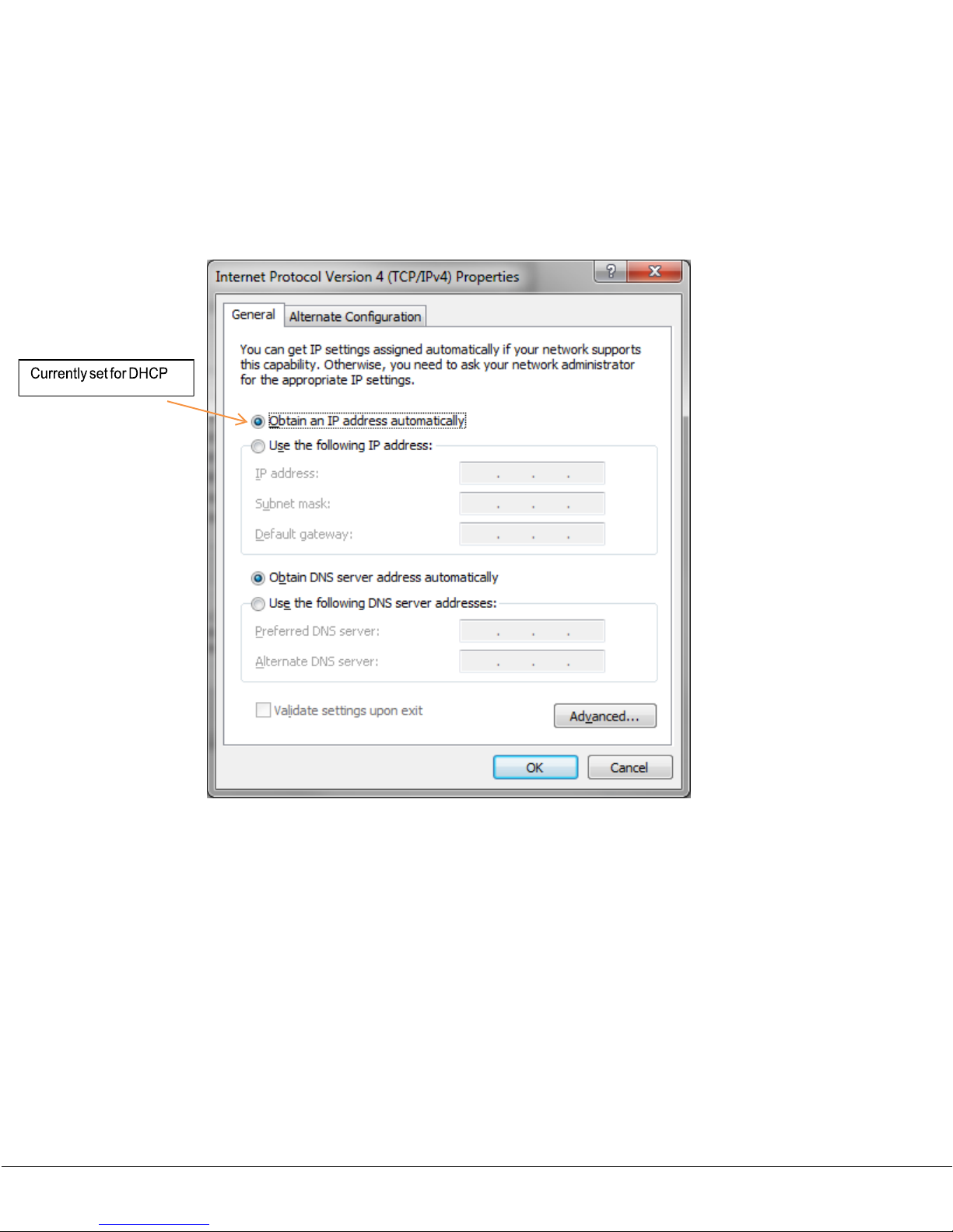
Select the “Internet Protocol Version 4 (TCP/IPv4) or in the case of an XP system “Internet
Protocol (TCP/IP)” and then click on the “Properties” button as shown in Figure 15.
Figure 15 Internet Protocol Version 4
100-
M0177X1
37 of 40
Page 38
GMS Inc. doing business as Cobham Tactical Communications and Surveillance
www.cobham.com/tcs
The default setting for many PCs is DHCP addressing as shown in Figxx.
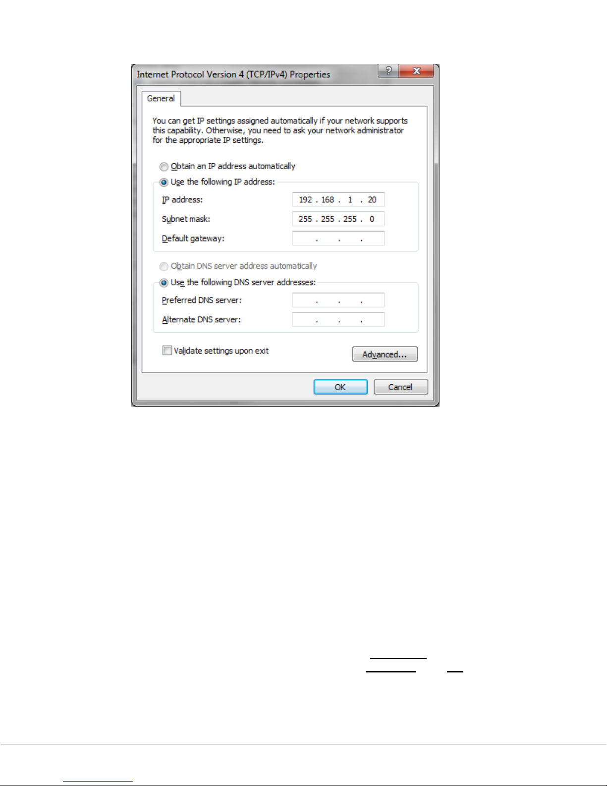
Check the “Use the following IP address” radio button. This sets the PC for static addressing.
Then enter a class C address such as 192.168.1.
20
under the “IP address” text box. Click in
the “Subnet mask” text box and the PC should automatically set the subnet mask
associated with the class C addressing. See Figure 16.
Figure 16 IP Address Setup
100-
M0177X1
38 of 40
Page 39
GMS Inc. doing business as Cobham Tactical Communications and Surveillance
www.cobham.com/tcs
Figure 17 Entering a Static IP addresss
That is all that is needed to be able to communicate with the M2ECHPT. Make sure to click
on the “OK” button and then exit the properties window. You should now be able to open
a Browser such as Microsoft IE and type in the default IP address of the M2ECHPT (in this
example it is 192.168.1.36) and it should be able to talk to it (make sure to plug in the IP
(Ethernet) cable from the M2ECHPT to the PC).
Keep in mind the following:
The IP address set for the PC as shown above in Figure 41 is its static IP address
(192.168.1.20),
do not enter the IP address of the M2ECHPT here
. The IP address of
the PC must be different from the M2ECHPT IP address; you cannot have two different
devices with the same IP address on a network. The “192.168.1” portion of this address
shows that it is a class C address with a network ID of
192.168.1.
The “
.20
” portion states
the host information. Host information can be set from 1 to 254. Zero (0), and 255 are
usually reserved or have special meaning, so do not use them. Hence as long as the
network ID is the same as the M2ECHPT the PC will be able to communicate with the
100-
M2ECHPT. So I could set the IP address of the PC to 192.168.1. <
M0177X1
1-254
> and it still would
39 of 40
Page 40

GMS Inc. doing business as Cobham Tactical Communications and Surveillance
www.cobham.com/tcs
be able to communicate with the M2ECHPT. For example instead of using 192.168.1.20, I
could use 192.168.1.30 or 192.168.1.5 or 192.168.1.60, etc.
Since the static IP address of the M2ECHPT also has a network ID of 192.168.1 (its IP
address is 192.168.1.36) the PC is able to communicate with it.
Remember IP addressing can be much more involved and complicated but the above
example should be enough to get things working.
A.2.
DHCP (Dynamic Host Configuration Protocol)
DHCP is an automated means of assigning a unique IP address to a device on a network.
The M2ECHPT can be set up for DHCP. If the server network to which the M2ECHPT is
connected provides DHCP services then it may be more practical to switch to DHCP
addressing. This can be done using the LAN interface see section 5.1.
Keep in mind if the M2ECHPT is set up for DHCP addressing then each time it gets attached
to the computer network the IP address may change (depending on the configuration of
the DHCP server; the IP addresses that it issues are leased for an limited amount of time,
once the leased has expired a new IP address may be issued). Hence when the M2ECHPT
IP (Ethernet) cable is attached to the computer network it may be necessary to find the
current IP address.
You can view the current IP settings, the current addressing mode and the current IP
address. In addition you can also change the mode and IP address using the serial port.
Reference the operations manual 100-M0172 as stated in section 5.1.
100-M0177X1
40 of 40
 Loading...