

Page 1
Technical Operations Manual
The most important thing we build is trust.
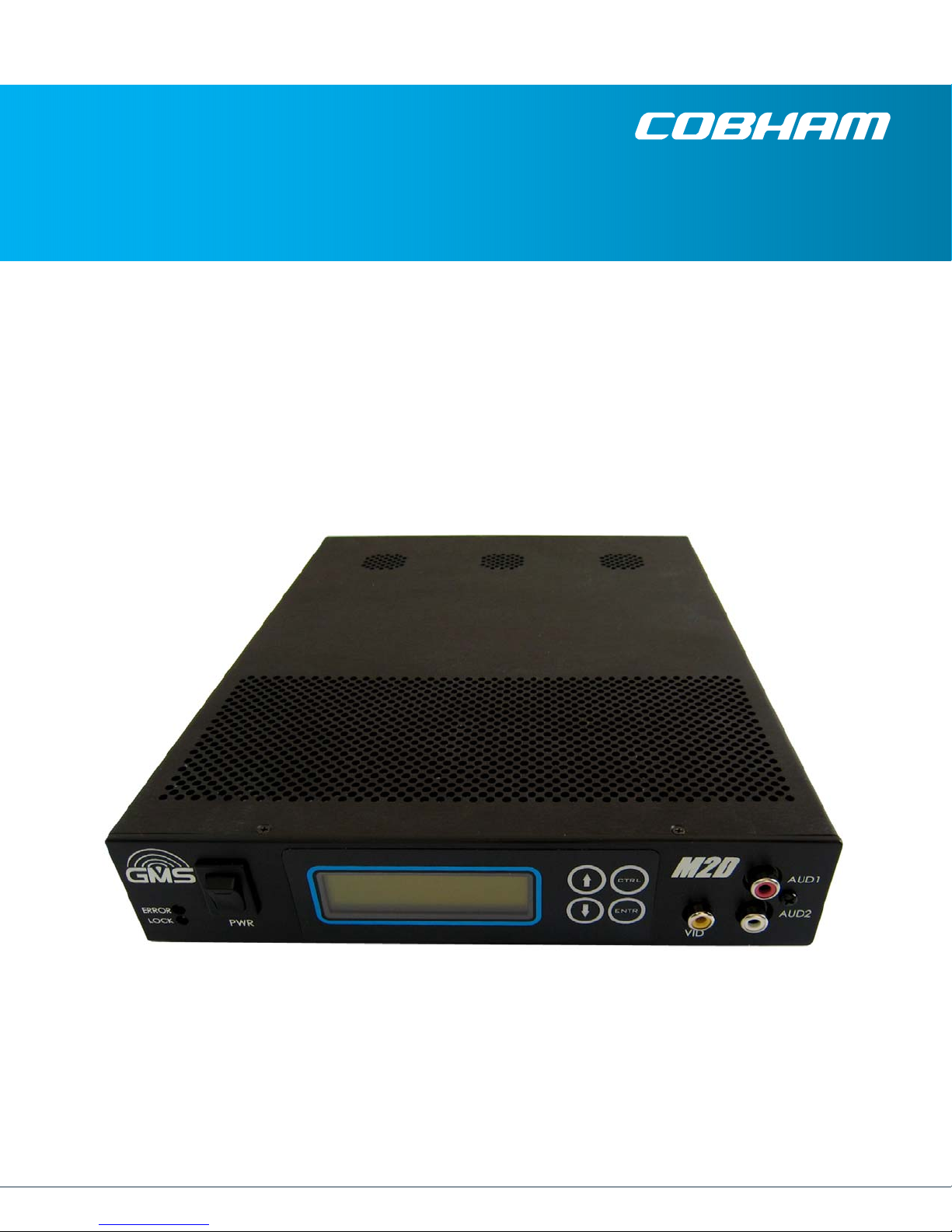
Messenger 2 Decoder
(M2D)
Cobham Surveillance
GMS Products
1916 Palomar Oaks Way Ste 100
Carlsbad, CA 92008
100-M0134X1B 07/15/10 T: 760-496-0055
F: 760-496-0057
www.cobham.com/gms
Page 2

Table of Contents
1. ACRONYMS ........................................................................................................................................................................... 5
2. INTRODUCTION ............................................................................................................................................................... 6
2.1 ABOUT THE MANUAL ................................................................................................................................................................. 6
2.2 THE MANUAL IS DIVIDED INTO THREE MAIN SECTIONS: ...................................................................................................... 6
2.3 WARRANTY .................................................................................................................................................................................. 6
2.4 SAFE OPERATING PROCEDURES ................................................................................................................................................ 6
3. GENERAL SYSTEM INFORMATION ..................................................................................................................... 7
3.1 M2D DESCRIPTION .................................................................................................................................................................... 7
3.2 PRODUCT HIGHLIGHTS ............................................................................................................................................................... 7
3.3 KEY SYSTEM FEATURES .............................................................................................................................................................. 7
3.4 THEORY OF OPERATION ............................................................................................................................................................. 8
3.5 N
4. INITIAL CHECK OUT ..................................................................................................................................................... 9
5. HARDWARE OVERVIEW ........................................................................................................................................... 11
ORMAL OR ULTRA-LOW LATENCY MODES .......................................................................................................................... 9
5.1 F
RONT PANEL DESCRIPTION .................................................................................................................................................. 11
5.1.1 ON/OFF Power Switch ............................................................................................................................................... 11
5.1.2 Local Control Panel ..................................................................................................................................................... 11
5.1.3 Status Indicators .......................................................................................................................................................... 11
5.1.4 A/V Connectors ............................................................................................................................................................. 12
5.2 REAR PANEL DESCRIPTION ..................................................................................................................................................... 12
5.2.1 DC PWR .............................................................................................................................................................................. 12
5.2.2 LAN ....................................................................................................................................................................................... 13
5.2.3 ASI IN ................................................................................................................................................................................. 13
5.2.4 ASI OUT ............................................................................................................................................................................. 13
5.2.5 HD-SDI/SDI ..................................................................................................................................................................... 13
5.2.6 SNYC .................................................................................................................................................................................... 13
5.2.7 Y,Pb,Pr ................................................................................................................................................................................. 13
5.2.8 VID ....................................................................................................................................................................................... 13
5.2.9 DVI ....................................................................................................................................................................................... 14
5.2.10 MISC I/O ...................................................................................................................................................................... 14
5.2.11 AUD 1 & AUD 2 ......................................................................................................................................................... 14
5.2.12 RF1 & RF2 .................................................................................................................................................................... 14
6. LOCAL FRONT PANEL DISPLAY & SCREENS EXPLAINED ................................................................. 14
6.1 F
LOW CHART (INCLUDING THE GENLOCK OPTION ) .......................................................................................................... 15
6.1.1 Main Menu ....................................................................................................................................................................... 15
6.1.2 Status Menu .................................................................................................................................................................... 16
6.1.3 Setup Menu ..................................................................................................................................................................... 18
6.1.4 System Setup .................................................................................................................................................................. 21
7. GENLOCK (OPTION) ..................................................................................................................................................... 23
8. EMBEDDED AUDIO (OPTION) .............................................................................................................................. 23
100-M0134X1B 2 of 40
www.cobham.com/gms
Page 3

9. MULTI PROGRAM TRANSPORT STREAM ..................................................................................................... 23
10. SPECIFICATIONS .......................................................................................................................................................... 24
11. UPGRADING NEW FIRMWARE THROUGH THE IP PORT ................................................................. 29
12. TROUBLESHOOTING SECTION ............................................................................................................................ 36
List of Figures
Figure 1 Block Diagram ........................................................................................................................................................................... 8
Figure 2 Check Out ................................................................................................................................................................................ 10
Figure 3 Front Panel .............................................................................................................................................................................. 11
Figure 4 Rear Panel ................................................................................................................................................................................ 12
Figure 6 Main ........................................................................................................................................................................................... 15
Figure 7 Status Menu ........................................................................................................................................................................... 17
Figure 8 Setup Menu ............................................................................................................................................................................ 18
Figure 9 Genlock Menu ....................................................................................................................................................................... 19
Figure 11 Web Interface .................................................................................................................................................................... 30
Figure 12 Authentication ................................................................................................................................................................... 30
Figure 13 Main Screen ......................................................................................................................................................................... 31
Figure 14 Browse for File .................................................................................................................................................................... 32
Figure 15 Progress Screen .................................................................................................................................................................. 33
Figure 16 Status Screen ...................................................................................................................................................................... 34
Figure 17 Xilinx Browse Screen ....................................................................................................................................................... 35
List of Tables
Table 1 Acronyms ..................................................................................................................................................................................... 5
Table 2 Ethernet Connector ............................................................................................................................................................ 24
Table 3 Pin Out MISC I/O ................................................................................................................................................................... 28
Table 4 Video Scaler Modes ........................................................................................................................................................... 28
Table 5 T/S................................................................................................................................................................................................. 36
List of Appendices
Appendix A – Cable, M2D, Mic Conn Pigtail (780-C0485) ............................................................................................... 38
Appendix B – Cable, M2D/MVRD ext Power, Pigtail (780-C0484) ............................................................................... 39
Appendix C – Power Cable (473-064) ......................................................................................................................................... 40
100-M0134X1B 3 of 40
www.cobham.com/gms
Page 4

Revision History
Version Date Main Changes from Previous Version Created by
X1 02-17-10 Initial Release TG
X1A 05-13-10 Add Embedded Audio feature TG.
X1B 07-15-10 Update LCD front menu to correspond to latest
Firmware release
TG.
100-M0134X1B 4 of 40
www.cobham.com/gms
Page 5

1. Acronyms
This section lists and describes the various acronyms used in this document.
Table 1 Acronyms
Name Meaning
A/V Audio/Video
AVC Advance Video Coding
CBR Continuous Bit Rate
CIF Common Intermediate Format 352 X 288 resolution
COFDM Coded Orthogonal Frequency Division Multiplexing
CVBS Composite Video
DHCP Dynamic Host Configuration Protocol
DVI Digital Video Interface
GUI Graphical User Interface
HDMI High Definition Multimedia Interface
I/O Input/ Output
KBaud Kilobaud per second
Kbps Kilobits per second
LAN Local Area Network
M2D Messenger 2 Decoder
M2T Messenger 2 Transmitter
Mbps Megabits per second
MDL Messenger Digital Link
MPEG Moving Picture Experts Group
MPTS Multi Program Transport Stream
NAL Network Abstraction Layer
NTSC National Television System Committee
PAL Phase Alternation Line
PID Packet Identifier
PMT Program Map Table
RF Radio Frequency
RX Receiver
TX Transmitter
VDC Volts (Direct Current)
UDP User Datagram Protocol
VBR Variable Bit Rate
100-M0134X1B 5 of 40
www.cobham.com/gms
Page 6

2. Introduction
2.1 About the Manual
This manual provides information on how to operate the M2D (Messenger 2 Decoder) as well as
pertinent technical information related to the overall system.
2.2 The manual is divided into three main sections:
Getting started and basic operation (sections 3 & 4)
This section describes to users how to deploy and use a M2D unit. It also provides basic theory
and general information regarding the M2D.
Advanced operation (sections 5 - 8)
This section describes the operation of the system, hardware details and optional features in more
depth.
Technical Specifications (section 9)
This section provides technical specifications and control protocol data and will be of interest to
those integrating the M2D into larger systems or using unusual configurations.
2.3 Warranty
GMS offers a 12 month standard product warranty. During this period, should the customer
encounter a fault with the equipment we recommend the following course of action:
Check the support section of the website (www.cobham.com/gms) for information on
that product and any software/firmware upgrades.
If a fault persists call our support line (760-496-0055, 888-880-9339) and report the
fault. If you are informed to return the product, please obtain an RMA number from the
GMS support department or website and ship the equipment with the RMA number
displayed and a description of the fault. Please email the airway bill/consignment number
for tracking purposes to our customer support department.
Depending on the nature of the fault GMS will attempt to repair the equipment and return it to
the customer within 14 days of the item arriving at our factory. Obviously at times there will be
circumstances beyond our control and delays are sometimes inevitable.
2.4 Safe Operating Procedures
If using an off the shelf power supply ensure it meets the requirements (see specifications
under section 9) before powering up the M2D.
Operate within the environmental limits (see section 9, specifications) specified for the
product.
Warranty could be voided if the unit is opened. There are no functions that required the user to
gain access to the interior of the product
100-M0134X1B 6 of 40
www.cobham.com/gms
Page 7

3. General System Information
3.1 M2D Description
The Messenger 2 Decoder (M2D) is a companion product to GMS’ Encoders and Transmitters
providing the highest Video Quality with Ultra-Low Latency and Fast Recovery essential for
Wireless coverage of Real-Time events such as Sports and Surveillance Applications. It supports HD
& SD AVC Baseline Profile Decoding with certain additions and exclusions as described in the
specification section below including interlaced support.
It provides AVC (Advance Video Coding) decoding with resolutions from CIF (Common
Intermediate Format) up to 1920 x 1080, frame rates to 60 frames per second with Progressive or
Interlaced formats, CBR (continuous bit rate) or VBR (variable bit rate) all with just 45 mS delay
when encoded with a GMS AVC encoder. Additionally with GMS’ AVC Encoders Instantaneous
Decoder Refresh or re-lock can occur on slice boundaries providing the fastest recovery from
corrupted streams. Both Frame and Field based Decoding is supported.
Note: The M2D supports Ultra-Low Delay mode of GMS Messenger 2 TXs (M2T & M2T-
C) only. Normal Mode is not currently supported.
3.2 Product Highlights
Provides Ultra-Low-Latency for Real-Time Applications(<44mS) when used with GMS’
Messenger 2 AVC Encoders and Transmitters
Built-in HD to SD Down-Conversion
Compact Design with Local Control & Monitoring
Optionally mounts to GMS MSR COFDM Rx
3.3 Key System Features
DVB-ASI and LAN** Inputs & Outputs
Supports ISO 13818 Transport Stream Demuxing & NAL Streams
Support up to 60 megabits per second H.264 stream processing
Pre-processing adaptive noise filter – MCTF
HD-SDI, DVI, Component & Composite Video Outputs
Balanced Analog Audio Outputs plus Digital Audio
SDI embedded audio
Optional Genlock Capability
Ethernet Port Connectivity (10/100 Mbits/s) for Streaming** and Control/Monitoring**
** Note: In Development
100-M0134X1B 7 of 40
www.cobham.com/gms
Page 8
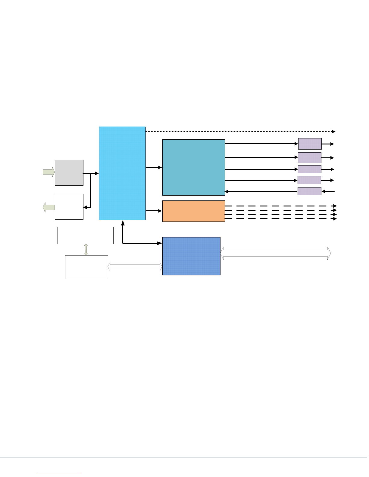
3.4 Theory of Operation
The M2D Decoder includes both DVB-ASI and Ethernet ports (refer to figure 1 block diagram
below). The system also offers a choice of transport protocols with support for AVC embedded
within a MPEG-2 TS (ASI input or over IP**) and raw H.264 bit streams. Both transport mechanisms
can be delivered over UDP** and RTP/UDP**. A compressed stream can be input from the DVB-ASI
interface, and reformatted for IP Streaming** and output at the same time that it is being locally
decoded.
Optional AES
Decryption
DVB-ASI
Input
Circuit
DVB-ASI
Output
Circuit
TS Demux
User Data
Extraction
AVC Decoder
Audio Decoder
User Data
HD-SDI/
SDI
DVI
Component
Composite
GEN Lock
Front Control Panel
Streaming
Streaming
Embedded
Controller
Processor
Control & Status
Control & Status
Figure 1 Block Diagram
The Decoder can be set to tune both video and audio in two ways: Auto or Manual. In Auto
mode the unit will self acquire the first MPEG program in the transport stream and decode the first
audio & video PID listed in the PMT for that Program.
In Manual mode the program number can be selected when Multi Program Transport Streams
(MPTS) are present. Within the selected MPEG program, each of the two** audio processors can
have an audio PID from that program selected.
The M2D can be controlled through its front-panel control interface. Additionally, it has two LED
status lights. The green “Lock” LED notifies user that the M2D has a valid ASI stream and is able to
decode the Transport Steam. The second red LED status light is for “Error” conditions.
The Decoder incorporates error resiliency features. In the event of damaged bit-stream the
Decoder can replace the corrupt slice with skips and resume decoding at the next NAL (Network
Abstraction Layer) unit. Alternatively it can freeze the output until a new I-frame is received.
** In Development
LAN
100-M0134X1B 8 of 40
www.cobham.com/gms
Page 9

3.5 Normal or Ultra-Low Latency Modes
All GMS Messenger products include two operating modes that relate to system latency. In
“Normal” latency mode GMS offers full compatibility with conventional digital video products. In
this mode, delay will be equivalent to the normal delay found in commercial equipment (250msec
to 500msec, decoder dependant).
The Ultra-low latency mode provides an incredibly low system latency of down to ~44msec plus“
propagation time! This unique capability provides the fastest response times to time critical
situations. The main contributor to normal operating mode latency is the size of the “I” or IntraRefresh frame and the time it takes for this to travel through the wireless link. The ‘I’ frame is
normally 5-7 times larger than the “P” or Progressive frames. In Ultra-low latency mode we perform
a non-conventional compression operation. We break-up the I-frame and send it in pieces along
with multiple P-frames. This tends to level or smooth the data throughput through our Constant Bit
Rate (CBR) wireless link. This allows the latency to be dramatically reduced!
.
This non-conventional operating mode is part of the MPEG standard. However, it is not universally
supported by all commercial vendors because many applications do not need to deal with its
complexity.
4. Initial Check Out
Prior to installing a M2D unit into the desired target environment, an initial checkout should be
performed to ensure proper operation of the unit. The initial checkout consists of taking an ASI
source and feeding it into the ASI IN of the M2D and ensuring video and audio are decoded.
The M2D is pretty much a ‘plug & play’ unit and thus is ready to work “right out of the box”.
Just supply a power source and power cable along with an ASI stream, switch on the unit and it will
start to decode without any input from the user.
The following power supply and power cable are available from the factory as follows:
780-C0485 Cable, M2D Mic Conn Pigtail
473-064-G Power Supply with Mic Connector
If a +12Vdc source is already available with the proper current handling capability (see
specifications under section 9) then only a pigtail cable with the proper connector needs to be
ordered.
780-C0484 Cable
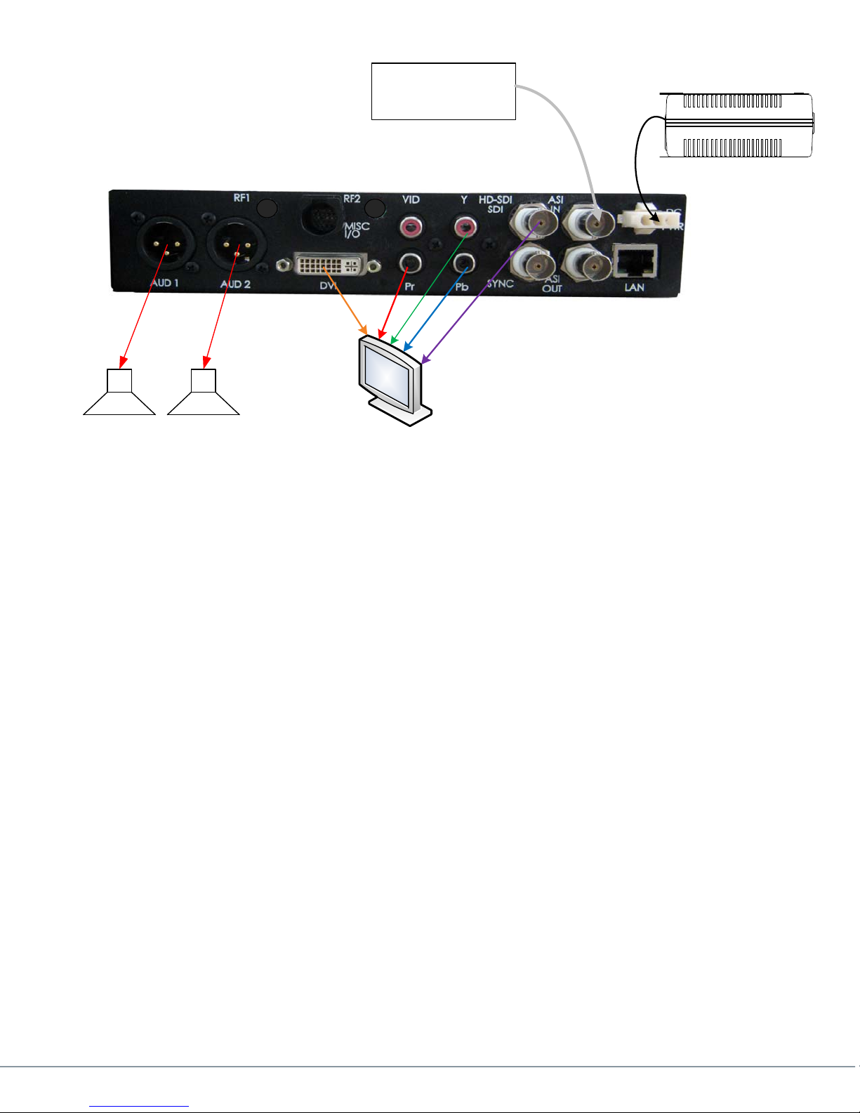
The basic setup is shown in Figure 2 below.
100-M0134X1B 9 of 40
www.cobham.com/gms
Page 10
Audio
ASI Source
Power Supply
+12Vdc
Figure 2 Check Out
Provide power to the M2D by attaching GMS # 473-064-G pigtail mic connector to the M2D
“DC PWR” connector and to GMS power supply 780-C0485. Plug the supply into a wall
socket.
Note: If using an off the shelf power supply ensure it can source at least 1.5A at
+12VDC and use GMS pigtail cable # 780-C0484 to attach to the M2D.
Attach a known good ASI stream (DVB compliant) into the ASI IN connector of the M2D.
Attach video cables from the video outputs to a monitor.
Attach audio cables from the audio XLR connectors to speakers.
Power on the M2D by toggling the “PWR” switch on the front panel to up position. The two
LEDs on the front panel momentarily turn on & off. After a few seconds the front panel LCD
lights and displays the “AVC Messenger 2 Decoder” logo and then displays the TS (transport
screen). It should decode the video and audio from the program on the TS. The front “LOCK”
green LED should light.
The initial checkout described above is simply to check the basic video operation of the M2D
unit.
100-M0134X1B 10 of 40
www.cobham.com/gms
Page 11
5. Hardware Overview
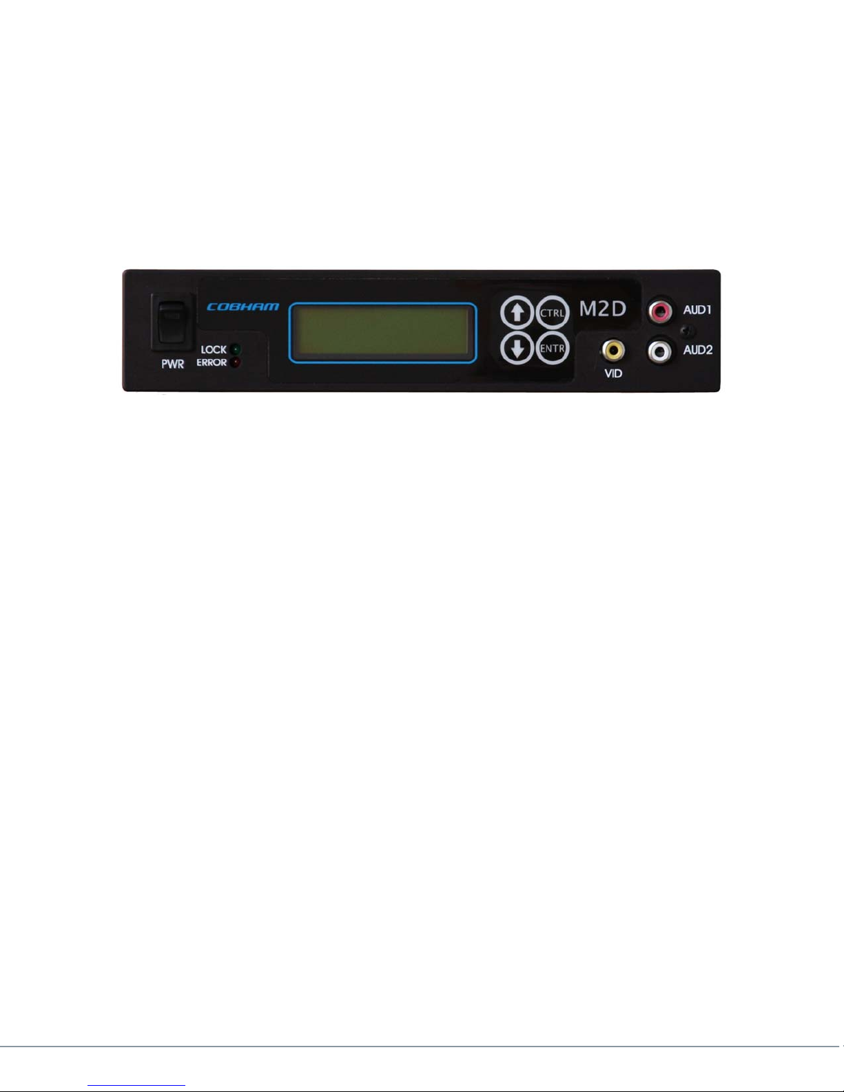
5.1 Front Panel Description
Front Panel view of M2D is shown in Figure 3 below. A brief description of the LEDs, power switch,
connectors, and front panel are stated below.
Figure 3 Front Panel
5.1.1 ON/OFF Power Switch
The PWR switch is a toggle type switch, up for ON and down for OFF.
5.1.2 Local Control Panel
The Local Control Panel consists of a backlit LCD Display (dual line, 16 characters per line) and
4-button keypad, ENTR, CTRL, the up and the down arrows.
Refer to the flowcharts (see section 6).
The CTRL key allows the user to sequence through each of the available menus.
The ENTR key allows the user to enter sub-menus when available and to confirm a
selection.
The UP and DOWN arrows are for toggling through various selections when available.
5.1.3 Status Indicators
The green LOCK LED lights when the M2D receives a valid MPEG Transport Stream (TS).
The red ERROR LED lights when an error occurs in the unit:
When the unit first powers up and when there is no TS, a corrupt TS or a non-valid TS
For units with the optional Genlock :
Genlock function is enabled but the M2D can’t lock to the reference Genlock
clock.
The Genlock reference input signal does not match the video format which is
decoded.
100-M0134X1B 11 of 40
www.cobham.com/gms
Page 12
Note: If the red error LED lights on the front panel and the unit has Multi-Program or
Genlock optional features installed then it’s a good idea to check the STATUS menu (see
section 6.2.2) for clues as to why the errors are occurring.
5.1.4 A/V Connectors
VID yellow RCA-F type connector is the port for Composite Video. When processing HD
AVC the composite video out is from an internal video scaler. When unable to scale the
output displays color bars.
Note: The Video Scaler does not always accurately represent the HD signal. Test
patterns with very narrow lines can be distorted by the scaler. However, it does an
acceptable job of converting normal video from a camera.
AUD 1 and AUD 2 red and white respectively are single ended audio outputs, type RCA-
F connectors. Audio levels are not adjustable from the M2D.
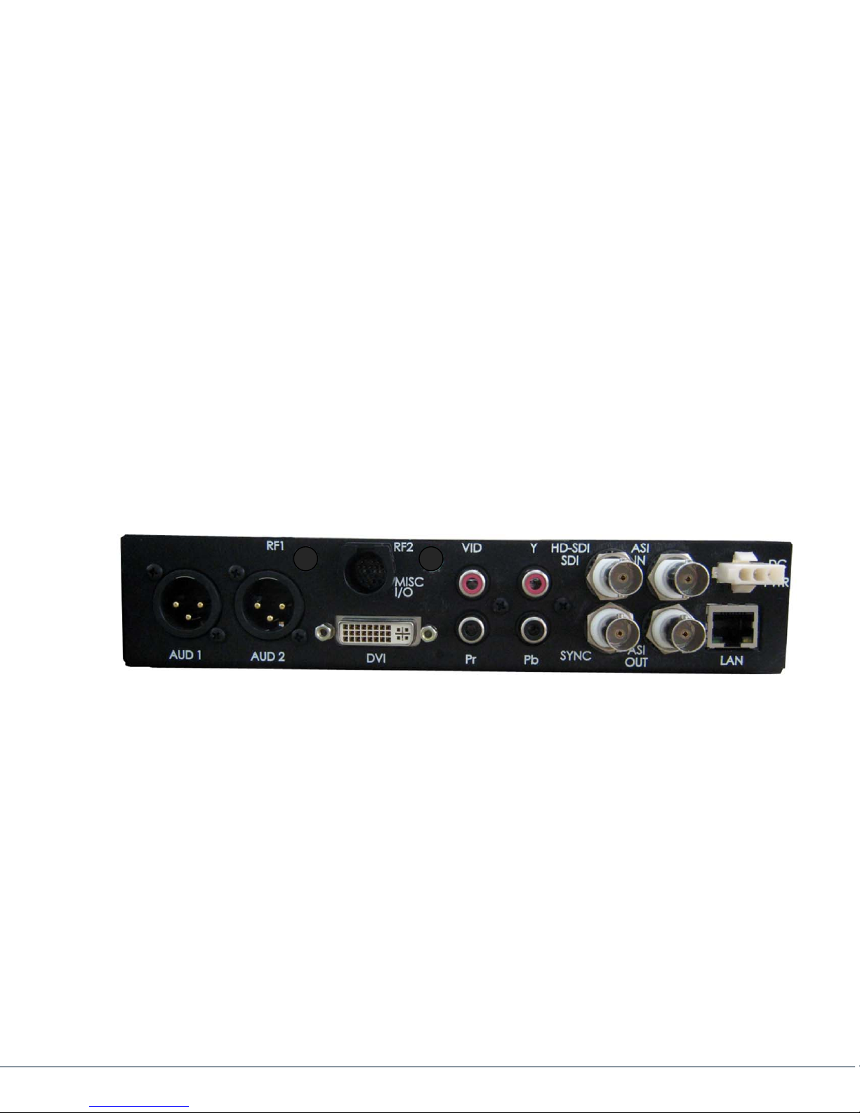
5.2 Rear Panel Description
Figure 4 shows the rear view of the M2D. A brief description of the connectors (type and
function) is mentioned here. Refer to the specifications section (section 9) for additional detailed
information.
5.2.1 DC PWR
The DC PWR consists of a three pin connector:
Pin 1: +Vcc (+12Vdc)
Pin 2: Return
Pin 3: Chassis Ground
Mating Connector Type: AMD Tyco Electronics PN: 172166-1
100-M0134X1B 12 of 40
Figure 4 Rear Panel
www.cobham.com/gms
Page 13

5.2.2 LAN
The LAN connector is a type RJ45 Ethernet 10/100 base T. It can be used to update new
firmware versions (see section 10), streaming video (future update) and for remote
operations (future update).
5.2.3 ASI IN
The ASI IN is the input connector (BNC-F) for an ASI stream (TS input/DVB compliant)
which are to be decoded.
5.2.4 ASI OUT
The ASI OUT is a loop-through output (connector type BNC-F) of the ASI stream presented
on the ASI IN connector.
5.2.5 HD-SDI/SDI
The HD-SDI/ SDI is an output (connector type: BNC-F) which can display high definition or
standard definition through the serial digital interface (SDI).
Available as an option; audio which is decoded is automatically placed on the SDI stream
(embedded). Only two channels are available and are mapped to channel 1 and channel 2.
5.2.6 SNYC
5.2.7 Y,Pb,Pr
5.2.8 VID
The SYNC is used as an input sync source for Genlock (a BNC-F connector).
Y, Pb and Pr are the three RCA-F output connectors for analog component video. These
connectors are not color coded according to industry standards. Y carries the luma, the
brightness & sync information (colors associated with this connector are usually green or
yellow).
Pb carries the difference between blue and luma (B-Y) and Pr carries the difference between
red and luma (R-Y). Blue & red colors are associated with these connectors respectively.
The VID connector (RCA-F) is a second composite video output which essentially mirrors the
front composite video output. As mentioned above when processing HD AVC the composite
video out is from an internal video scaler. When unable to scale the output displays color
bars.
Note: The Video Scaler does not always accurately represent the HD signal. Test
patterns with very narrow lines can be distorted by the scaler. However, it does an
acceptable job of converting normal video from a camera.
100-M0134X1B 13 of 40
www.cobham.com/gms
Page 14

5.2.9 DVI
The DVI (Digital Video Interface) connector (DVI-I socket-female) is an output which
provides another means of viewing the video into a monitor with a DVI connector or it can
be converted to HDMI (using a external adapter) Composite signals (NTSC & PAL) are not
available through this output.
5.2.10 MISC I/O
The MISC I/O is a specialized connector (see the specifications section 9 for details and pin
outs) which contains the signals for RS232 user data (future update), USB control (future
update) and digital audio (future update).
5.2.11 AUD 1 & AUD 2
AUD 1 and AUD 2 are XLR-M connectors providing balance audio out. Audio levels (gain)
are not adjustable from the M2D
5.2.12 RF1 & RF2
These spaces are reserved for RF inputs which are not used on the M2D.
6. Local Front Panel Display & Screens Explained
NOTE: The words display and screen are used interchangeably.
The M2D’s front panel LCD display and various screens are explained in this section.
When power is first applied the LCD backlight lights up and within 5 seconds or so the unit boots up
and displays the product type, in this case it’s a Messenger 2 AVC Decoder. The display then
changes to the MAIN menu screen. This screen as explained below gives the user a quick status of
the system. For example it shows if a TS (transport stream) is present, if audio and video are being
decoded and in addition it shows the decoded video format.
In general the CTRL button sequences through the top level menus or if in a submenu it will
traverse through each of the menu options within the submenu. The ENTR button allows the user
to enter a submenu if presented with a choice to do so and it also allows the user to confirm a
selection when more than one option is available. In some cases the ENTR button can act as a
shortcut and allows the user to jump to a setup menu. The UP and DOWN arrows allows the
user to choose between various options when presented with them. When you see the following
symbol in a screen then you have other options to select from:
100-M0134X1B 14 of 40
www.cobham.com/gms
Page 15

6.1 Flow Chart (including the Genlock option )
This section explains the various screens available to the user. The menu structure consists of the
Main menu page, the Status menu page, the Setup menu page (which is broken down into the
Genlock and Program submenus) & the System menu page.
6.1.1 Main Menu
The M2D boots up in the MAIN menu which is shown in figure 6 below. The Main menu is
literally the status of the TS (transport stream). It shows the user at a glance if a TS is present
with a capital ‘Y’ for yes or an ‘N’ for no. It shows if a Prg (program) is present on the transport
stream with the same indicators ‘Y’ or ‘N’. It also shows if ‘Aud (audio) and VID (video) are
present. All menus returning to the MAIN menu return here.
Messenger 2
AVC Decoder
1
MAIN MENU
TS: Prg: Aud:
Y Y Y
720p59.94 Vid:
CTRL
2
3
4
ENTR
ENTR
ENTR
[ENTR] for
STATUS MENU
CTRL
[ENTR] for
SETUP MENU
CTRL
[ENTR] for
SYSTEM MENU
CTRL
Y
100-M0134X1B 15 of 40
Figure 6 Main
www.cobham.com/gms
Page 16

6.1.2 Status Menu
The following displays are found under the STATUS menu (refer to figure 7 below):
The IP Address is displayed under the “IP ADDR (DHCP)” screen when an IP LAN cable
The next screen displays the Genlock status. It states the Mode (ON, OFF, AUTO), if
The next display is the “Number of Programs in TS: xx”. It shows the number of
The “Selected Prg: xx” display shows the current selected program and then
Finally the last display offers a chance to return to the MAIN menu or to return to
(from a network) is attached to the LAN input connector (on the rear of the M2D )
and if the server can provide DHCP services. The M2D does not support static IP
addressing at this time (future updates will have this feature). You will need to know
the address when upgrading to new firmware.
it’s locked (Y or N), shows the reference signal format (REF:), and shows the decoded
output video format (OUT). This screen is valuable in determining if Genlock is
working as expected. In addition if the red error LED lights the Genlock status screen
should be monitored to determine if there is a conflict or error with the Genlock
setup. Pressing the ENTR key while in this display takes you immediately to the
Genlock Setup Menu.
programs in the current TS. Pressing the ENTR key while in this display takes you
immediately to the Program Setup menu.
automatically cycles through the PCR, Video, Audio and PMT PIDS for this program.
Pressing the ENTR key while in this display take you immediately to the Program
Setup menu.
the start of this menu (the STATUS menu).
100-M0134X1B 16 of 40
www.cobham.com/gms
Page 17

Figure 7 Status Menu
100-M0134X1B 17 of 40
www.cobham.com/gms
Page 18

6.1.3 Setup Menu
The Setup menu provides entry to the Genlock and Program submenus and also offers the
option to return to the Main menu. The menu structure below in figure 8 is self-explanatory.
3
SETUP MENU
6
5
1
ENTR
ENTR
ENTR
[ENTR] for
GENLOCK MENU
CTRL
[ENTR] for
PROGRAM MENU
CTRL
[ENTR] for
MAIN MENU
CTRL
Figure 8 Setup Menu
6.1.3.1 Genlock Menu
Note: Two flowcharts are shown in figure 9 for the Genlock menu. One is when
Genlock is ON and the other is when Genlock is OFF. Also refer to section 7.0 for an
explanation of the various Genlock setup options.
The first screen presents the user with the options to turn Genlock ON, OFF or to
AUTO. If ON and there is no reference signal or incorrect reference on the SYNC input
(see section 5.2.6) the red error LED on the front panel lights. Otherwise if the reference
is correct the green LOCK LED on the front panel lights. If OFF Genlock is disabled
regardless if and what type of reference signal is on the SYNC input. . In AUTO mode
Genlock automatically locks if there is a reference signal on the SYNC in which it can
lock to.
If Genlock is ON then the Genlock offset Pixels and Genlock Offset Lines screens are
shown otherwise they are not. These screens give the user the option of adjusting the
100-M0134X1B 18 of 40
www.cobham.com/gms
Page 19

Genlock signal offset in terms of pixels or lines. The total number of pixels or lines
available for adjustment is determined by the type of reference signal on the SYNC
input.
The remaining displays allow the user to either return to the MAIN menu or to the
SETUP menu.
Once Genlock has been setup it can be monitored from the STATUS menu, see section
6.2.2 (and figure 7). The STATUS menu “Genlock” screen shows if Genlock is locked, if it is
ON, OFF, or in AUTO mode, if a reference signal is present (and the format), and the output
video format the decoder is decoding.
6
GENLOCK SETUP
Genlock Mode:
ON
CTRL
Genlock Offset
Pixels: 2
CTRL
(ON)
ENTR
3
6
GENLOCK SETUP
Genlock Mode:
OFF
CTRL
[ENTR] for
SETUP MENU
CTRL
(OFF)
Genlock Offset
Lines: 1
CTRL
3
1
ENTR
ENTR
[ENTR] for
SETUP MENU
CTRL
[ENTR] for
MAIN MENU
ENTR
1
[ENTR] for
MAIN MENU
CTRL
CTRL
100-M0134X1B 19 of 40
Figure 9 Genlock Menu
www.cobham.com/gms
Page 20

6.1.3.2 Program Menu
The PROGRAM menu allows users to choose AUTO or MANUAL mode detection.. The
PROGRAM menus (see figure 10 below) are displayed a little differently depending on which
mode is selected. Basically if decoding a multi-program stream then MANUAL mode offers
the user the ability to choose the desired program which is to be decoded. AUTO mode is
mainly for a TS with a single program. If the TS has multi-programs and the M2D is in
AUTO mode then the first program it can detect (from the PAT table) is decoded,
The “SELECTED PRG: #” display shows which program is currently being decoded and it
cycles through the PIDs of the decoded program...
NOTE: If the M2D is power cycled and it was previously set for MANUAL program
detection it remembers the specific program number it was decoding. Hence if for some
reason that particular program number is no longer present then another program
number needs to be selected from the “MANUAL PROGRAM” display in order for
decoding to continue.
PROGRAM MENU
These items are
displayed one line
at a time and are
continuously
cycled until the
CTRL key is
pressed
3
1
[AUTO]
ENTR
ENTR
5
Program Mode:
AUTO
CTRL
Selected Prg: xx
Mode: Auto
PCR PID: 0x0050
Video PID: 0x0022
Audio PID: 0x0034
PMT PID: 0x0020
CTRL
[ENTR] for
SETUP MENU
CTRL
[ENTR] for
MAIN MENU
PROGRAM MENU
[MANUAL]
These items are
displayed one line
at a time and are
continuously
cycled until the
CTRL key is
pressed
3
1
Program Mode:
MANUAL
Manual Program:
Selected Prg: xx
Mode: Manual
PCR PID: 0x0050
Video PID: 0x0022
Audio PID: 0x0034
PMT PID: 0x0020
ENTR
SETUP MENU
ENTR
MAIN MENU
5
CTRL
1
CTRL
CTRL
[ENTR] for
CTRL
[ENTR] for
100-M0134X1B 20 of 40
CTRL
CTRL
Figure 10 Program Menu
www.cobham.com/gms
Page 21

6.1.4 System Setup
The following screens are found und the System menu.
There are three firmware versions labeled DSP, Xil, and Dec. The firmware versions are
displayed in the first screen one line at a time (briefly) and the versions are continuously
cycled until the CTRL key is pressed. If updating to new code this is a good place to check
to see if the new versions are actually correct.
The next two displays, ‘Hardware Version’ and ‘Serial Number’ are self-explanatory. The
serial number should be recorded in case it’s needed when talking to customer service.
The next screen displays the model name.
The final screen gives the user the ability to get back to the Main menu.
100-M0134X1B 21 of 40
www.cobham.com/gms
Page 22

4
SYSTEM MENU
Firmware Version
DSP: x.xxx
Xil: xxxxxxxx
Dec: xxxxxxxxx
CTRL
Hardware
Version: x
CTRL
Serial Number:
xxxxxxx-xx
CTRL
MODEL NAME:
MESSENGER 2
These items are
displayed one line
at a time and are
continuously
cycled until the
CTRL key is
pressed
CTRL
[ENTR] for
MAIN MENU
CTRL
ENTR
1
Figure 11 System Menu
100-M0134X1B 22 of 40
www.cobham.com/gms
Page 23

7. GenLock (option)
Genlock is a means to ensure video signals are synchronized; this is an optional feature and is not
available on all units. The specifications for Genlock are listed in section 9, “Genlock Option”. The
Genlock input signal is attached to the SYNC BNC connector on the rear of the M2D (see rear
panel description, 5.2).
Genlock can be setup under the GENLOCK MENU (see section 6.1.3.1). This is where it can be
turned ON, OFF or to AUTO and offsets (pixels or lines) can be adjusted. Once Genlock has been
setup it can be monitored under the STATUS menu (see section 6.1.2). Under the STATUS menu
Genlock is continuously monitored and shows the reference signal format (if there is one) the
video format which is being decoded and the current mode it is set to (ON, OFF, AUTO).
A brief description of the operating modes (ON, OFF, AUTO) are described below:
ON keeps the Genlock function enabled regardless if there is a reference signal on
the SYNC input. If a TS is present the audio & video are processed with or without a
Genlock reference signal. However, extra latency is added to the decoding process
with Genlock always ON. (see specifications section 9).
AUTO mode turns the Genlock function OFF until it detects a reference signal on
the SYNC input connector. If a TS is present audio & video are processed with or
without a Genlock reference signal. If a reference signal is detected the Genlock
function is enabled. The benefit to this mode is that until a reference signal is
detected on the SYNC input the Genlock function is essentially OFF and therefore
the decoding latency is not increased.
OFF mode keeps the Genlock function disabled regardless if there is a reference
signal on the SYNC input.
In addition to the operating modes, Genlock synchronization can be adjusted with the pixels or
lines of the reference signal. The numbers of lines or pixels which are available correspond to the
reference signal video format.
8. Embedded Audio (option)
The audio on the TS which is decoded is automatically embedded into the SDI output along with
the video. Only two channels are supported and they are mapped to channel 1 and channel 2 on
the output. The sample rate supported is 48 KHz. There are no controls or selections to enable,
this is done automatically.
9. Multi Program Transport Stream
Transport Streams containing multi-programs can be decoded. Up to 16 programs can be detected
from the PAT table, all others are ignored. Users can decide which program to decode when the
decoder is set up for MANUAL under the PROGRAM menu setup (see section 6.1.3.2).
The PIDS (PCR, Video, Audio & PMT) of the current program selected are displayed under the
PROGRAM setup menu and in addition are monitored and displayed under the STATUS menu (see
the “Selected Prg: #” screen).
If running a multi-program TS and the decoder is set for AUTO (under the PROGRAM menu setup
it) will decode the first program it finds in the PAT table.
100-M0134X1B 23 of 40
www.cobham.com/gms
Page 24

Note: When running in MANUAL mode the M2D decoder remembers the program number
it currently is decoding. If for some reason the program number becomes unavailable the
decoder will not continue decoding until another program number (which is available) is
selected. It will however show if a particular program number is no longer available.
10. Specifications
Serial Transport Stream I/O
General
Configuration: DVB-ASI or LAN IP**, selectable
ASI Serial TS Input/Output
# of ASI Inputs: 1, BNC-F
# of ASI Outputs: 1 (loop-through), BNC-F
Max TS Rate: Up to 150 Mbps
IP Serial Input/Output**
# of Ethernet Ports: 1, RJ-45
Streaming Format: ** RTP/UDP; IP Unicast or Multicast
Supports MPEG-2: Transport Stream over UDP or RTP
Output: ** DVB-ASI input can be reformatted for streaming and output at the same
time that it is being decoded.
Table 2 Ethernet Connector
ConnectorName ConnectorType Pin Function
Ethernet RJ45 1 Transmit+
Ethernet RJ45 2 Transmit‐
Ethernet RJ45 3 Receive+
Ethernet RJ45 4 NC
Ethernet RJ45 5 NC
Ethernet RJ45 6 Receive‐
Ethernet RJ45 7 NC
Ethernet RJ45 8 NC
MPEG Decoder (Video, 2 Audio)
General
Compatibility Standard: MPEG-4 AVC/H.264 Baseline Profile Plus
Interlace Support
Bit streams Accepted: AVC video in MPEG TS per ISO/IEC 13818-2
PES packets per ISO/IEC 13818-1
Video Bit Rate: 1 Mbps to 60 Mbps
Video Decoder
Format @ Frame rate: 1080P @ 30Hz, 29.97Hz, 25Hz, 23.98Hz, 24Hz
1080I @ 30Hz, 29.97Hz, 25Hz, 23.98Hz, 24Hz
1080PsF @ 30Hz, 29.97Hz, 25Hz, 23.98Hz, 24Hz
100-M0134X1B 24 of 40
www.cobham.com/gms
Page 25

720P @ 60Hz, 59.94Hz, 50Hz
480I @ 29.97Hz
576I @25Hz
Display modes supported: Letterbox**, Cropped
Aspect Ratio: 16x9, 4x3 (selectable - format dependant)
Audio Decoder
Decoder Capabilities: MPEG-1, layers I and II
MPEG-2, layer II,
MPEG-2 PES Formats: MPEG-2, MPEG-1
Audio Source: Selected Audio Services 1-4
Video Output
General
Output connectors: Qty 1 -HD-SDI, Qty 1 – DVI, Qty 1- Component,
SD Only - Qty 2 – Composite
Output formats supported: 1920 x 1080 Progressive
1920 x 1080 Interlaced
1280 x 720 Progressive
720 x 480 Interlaced
720 x 576 Interlaced
Frame rates: 60/50/30, 59.94/29.97, 25, 24, 23.98Hz
(progressive/interlaced)
PsF supported with Interlaced Format
(1080p limited to 30 frames per second max)
Aspect Ratio: 16x9 (fixed: 1080i, 720p)
16x9, 4x3
Display Modes (selectable): HD: Letterbox**, Cropped, Full
SD: Letterbox**, Cropped
HD-SDI (High Definition Serial Digital Interface)
Standard: SMPTE 292M
Data Bit Rate: 1.485Gbps
# of Serial Outputs: 1
Connector: BNC (x1), female
Embedded Audio (Future Option)**
Embedded audio format: SMPTE299M
Sample rates supported: 32, 44.1, 48KHz
Sample rate out: 48 KHz
# embedded audio ch pairs: 4 (2 complete audio groups)
Audio types supported: MPEG2 layer 1 and 2
Embedded audio control: Selectable, .type./disable
(each pair independently controlled)
Analog Video
SD
Video format standards: PAL & NTSC Composite
# of Analog outputs: 2
Connectors: RCA-F
100-M0134X1B 25 of 40
www.cobham.com/gms
Page 26

HD
Video format standards: Component
# of Analog outputs: 1 set (Y, Pb, Pr)
Connectors: RCA-F
DVI (Digital Visual Interface)
DVI Connector: DVI-I Socket – Female
Note: Can be converted to HDMI (Video Only) with external adapter (Sold Separately)
Audio Output
General
# of Services: 2 Mono or 1 Audio Stereo Pairs
4 Mono** or 2 Audio Stereo Pairs**
Embedded Audio (Option)
Embedded audio fomat: SMPTE299M
Sample rate supported: 48 KHz
# embedded audio ch pairs: 2 channels
Note: Audio on the TS which is decoded is automatically embedded on the SDI output stream
along with Video. Only two channels are supported and are mapped to channel 1 and channel 2.
Analog Audio Out
Output Type: Balanced, 2 channel pairs (+/-, L/R)
Connectors: Qty 2 – XLR-M
Qty 2- p/o High density 15-pin D-sub, female
Cable w/Optional connectors: DB15 to Qty 2 - XLR-M
Impedance: 600 ohms nominal
Remote Operation/Update Interface
Type: Ethernet, 10/100 BaseT
Connector: RJ45
Serial Remote operation interface
Type: USB
Connector USB-A
Front Panel Indicators
Input LED: Green indicates valid input on selected input,
Off indicates no valid signal on the selected input
Error LED: Red indicates error is occurring
OFF indicates no errors detected
Power
DC Input: +9 to +36 VDC
DC Power: 15 Watts
AC Input Option: Via External Power Supply
100-M0134X1B 26 of 40
www.cobham.com/gms
Page 27

Voltage Range: 100 - 120/ 200 – 240 VAC
Power: Maximum – 200 W
Frequency: 47 – 63 Hz
Line cord: Detachable, 3-prong
Cooling: Forced air
General
Operating Temperature: 0 to 50 degrees C
Operating Humidity: <95% Non-Condensing
GENLOCK (Option)
Genlock capability: HD – SD
Genlock Reference: 480i @ 29.97, Ref NTSC “black and burst”
1080i @ 29.97 fps
Ref NTSC “black and burst” or 1080i tri-level sync @ 29.97 fps
1080i @ 30 fps – Ref 1080i tri-level sync @30fps
1080i @ 25 fps – Ref 1080i tri-level sync @25fps
720p @ 50 fps – Ref 720p tri-level sync @ 50 fps
720p@ 59.94 fps–Ref 720 tri-level sync @ 59.94 fps
720p @ 60 fps – Ref 720 tri-level sync @ 60 fps
Fps = frames per second
NOTE: Genlock functions can add additional latency to the decoding
process. Approximately 3 fields in 1080i formats and 1to 2 frames in
720p formats
Physical Dimensions: 8.5” (W) X 10.75” (L) X 1.75” (H) (2” with feet installed)
21.6 cm (W) X 27.3 cm (L) X 4.5 cm (H)
Weight: 2.89lbs
*: Option
**: in Development. This feature will be supplied as a field FW update, when available.
Miscellaneous I/O connector
The MISC I/O (see figure below) is a specialized connector containing signals for digital audio, RS232
user data and USB control. The table below shows in detailed the signal types and the pin outs for each
signal.
NOTE: These features, RS232 user data, digital audio and USB control are future upgrades for
the M2D.
100-M0134X1B 27 of 40
www.cobham.com/gms
Page 28

Table 3 Pin Out MISC I/O
Pin
Number
1
2
3
4
5
6
7
8
9
10
11
12
13
Audio SPDIF AN
Audio SPDIF AP
Audio SPDIF BN
Audio SPDIF BP
Audio Analog 3P
Audio Analog 3N
Audio Analog 4N
Audio Analog 4P
Ground Audio SPDIF
Not connected
Not connected
Not connected
Not connected
Pin Signal Name Pin Number Pin Signal Name
14
15
16
17
18
19
20
21
22
23
24
25
Not connected
Not connected
RS232 RX User Data
RS232 TX User Data
Ground RS232
Not connected
Not connected
USB Dn (Control)
USB VCC (Control)
USB Dp (Control)
Ground USB (Control)
Ground Audio Analog
VideoScaler
When processing HD AVC the composite video comes from an internal Video Scaler. The table below
shows details of the scaling and the valid configurations.
Table 4 Video Scaler Modes
InputFormat
480i,YCbCr,4:2:2 59.94Hz 720 480 1 1 NoScale
576i,YCbCr,4:2;2 50Hz 720 576 1 1 NoScale
100-M0134X1B 28 of 40
InputField/
{Frame}Rate
Input
Pixels
Input
Lines
Horizontal
Scale(720)
Vertical
Scale(576or
480)
www.cobham.com/gms
OutputFrameRate
Page 29

480p,YCbCr,4:2:2 {59.94} 720 480 1 1 480i(Interlace)
576p,YCbCr,4:2:2 {50} 960 576 1 1 576i(Interlace)
720p,YCbCr,4:2:2 {23.98} 1280 720 NotSupported
720p,YCbCr,4:2:2 {24} 1280 720 NotSupported
720p,YCbCr,4:2:2 {25} 1280 720 .5625 .8 576i50(Interlace)
720p,YCbCr,4:2:2 {29.97} 1280 720 .5625 .666 480i59.94(Interlace)
720p,YCbCr,4:2:2 {30} 1280 720 NotSupported
720p,YCbCr,4:2:2 {50} 1280 720 .5625 .8 576i50(Interlace)
720p,YCbCr,4:2:2 {59.94} 1280 720 .5625 .666 480i59.94(Interlace)
720p,YCbCr,4:2:2 {60} 1280 720 .5625 .666 480i59.94(Interlace)
1080p,YCbCr,4:2:2 {23.98} 1920 1080 NotSupported
1080p,YCbCr,4:2:2 {24} 1920 1080 NotSupported
1080p,YCbCr,4:2:2 {25} 1920 1080 NotSupported
1080p,YCbCr,4:2:2 {29.97} 1920 1080 NotSupported
1080p,YCbCr,4:2:2 {30) 1920 1080 NotSupported
1080i,YCbCr,4:2:2 50 1920 1080 .375 .533 576i50
1080i,YCbCr,4:2:2 59.94 1920 1080 .375 .444 480i59.94
1080i,YCbCr,4:2:2 60 1920 1080 NotSupported
Note: Future enhancements will allow all the operating modes to be supported.
The Video Scaler does not always accurately represent the HD signal. Test patterns with very
narrow lines can be distorted by the scaler. However, it does an acceptable job of converting
normal video.
11. Upgrading New Firmware Through the IP Port
This section explains how to load the M2D with new firmware releases. There can be up to three
separate firmware loads. They are usually labeled as D; X & W.
D: The LCD displays DSP code as a “D:” (this code is always updated with the “.out
file)
X: The LCD displays this FPGA code (for Xilinx) as an “X” (this code is always updated
with a “.bit
” file)
W (also noted as “DEC”): The LCD displays this FPGA code (for the Altera) as a “W” or
“DEC” (this code is always updated with an “.rbf
The correct file type (.out, .bit, or an .rbf) must be selected before programming.
Step 1:Open Microsoft Internet Explorer or Firefox and type in the IP address, see section 6
(6.1) on how to acquire the IP address from the M2D. See figure xx below. The Web
Interface opens…click on the “continue” button.
100-M0134X1B 29 of 40
”
” file).
www.cobham.com/gms
Page 30

Figure 11 Web Interface
Step 2: Next an “Authentication required” text box appears. Type in “admin” for User Name
and “admin” for Password.
Step 3: The main M2 AVC Decoder screen opens, see figure 13 below. Select
“System/Upgrade/DSP Firmware“(or the corresponding firmware which needs to be
100-M0134X1B 30 of 40
Figure 12 Authentication
www.cobham.com/gms
Page 31

loaded….Xilinx or Altera). This example deals with the DSP upgrade, however all upgrades
are very similar.
NOTE: If a firmware upgrade is necessary customer service notifies the end user as to
which firmware load is necessary and sends the link to the FTP site where the correct file
can be downloaded.
Figure 13 Main Screen
Step 4: The “Browse” for file screen opens. See Figure 14. Scroll down to the bottom of
the screen and click on the “Browse” button to browse for the correct file. Remember in this
example the DSP firmware is being updated so the “.out” file is the correct file to use. Also in
this example the DSP presents a checkbox choice for the “Program Number”; 1 for
“(factory)” or 2 for “(field upgrade”.) The “field upgrade” checkbox should be selected.
What this ensures is that the new firmware will be loaded from location 2. If for some reason
the new load is corrupted (or does not load correctly) the M2D will fall back to the firmware
in location 1 (the firmware which was running before the upgrade). Also it is not necessary to
check the “Update Boot Loader”. This is done during the initial programming of the flash at
the factory.
100-M0134X1B 31 of 40
www.cobham.com/gms
Page 32

#2shouldbe
checkedfor
fieldupgrades
Figure 14 Browse for File
Step 5: After browsing for the correct file and it’s been placed into the “File Name” text box,
click on the “Upload File and Program Flash” button. The “Progress” screen appears (see figure 15
below). Wait until the programming is complete before removing power or taking any other
action.
100-M0134X1B 32 of 40
www.cobham.com/gms
Page 33

Figure 15 Progress Screen
Step 6: After the file has been written into Flash an update status screen appears (see figure 16)
notifying the user that the file was successfully written into Flash (or not). To run the new code
the M2D must be re-powered. The new version (s) should also show up under the “Version” LCD
screen (see section 6.22 & 6.1).
100-M0134X1B 33 of 40
www.cobham.com/gms
Page 34

Figure 16 Status Screen
NOTE… Although the example above deals with uploading new code for the DSP the
procedure is almost exactly the same for loading new FPGA (Xilinx or Altera) code. The only
difference is the “Browse” screen. There are no check boxes to worry about (see figure 17
below)
100-M0134X1B 34 of 40
www.cobham.com/gms
Page 35

Figure 17 Xilinx Browse Screen
100-M0134X1B 35 of 40
www.cobham.com/gms
Page 36

12. Troubleshooting Section
Table 5 T/S
FAULT CONDITION
ACTION
LCD displays “TS = N”
Ensure ASI source output is connected to the
correct ASI INPUT BNC connector on the
rear of the M2D decoder. See figure below
ASI IN
Rear
SDI
Composite
ASI OUT
Component
DVI
Audio 1 & 2
M2D Rear View
Check carefully the indicators in the TS
(transport stream) LCD screen and ensure
“TS=Y” (this indicates there is a valid transport
stream).
.
Power
Cable
No Video Out
IF “TS=N” then this is indicative of a non-
valid or corrupt transport stream. Check the
ASI source
Check carefully the indicators in TS (transport
stream) LCD screen (see figure below). Y =
yes, N = no.
IF TS = Y, PRG = Y and VID = Y and the screen
indicates a video format such as “720p59.94”
then chances are it is receiving and decoding
an ASI stream. If this is the case check the
video out BNC connectors on the rear of the
M2D and ensure they are correctly connected
to the video monitors, that the video
monitors are on and they are capable of
receiving the format indicated.
TS: PRG: AUD
Y YY
720p 59.94 VID:
Y
If TS = Y, PRG = Y and VID = Y but no video
100-M0134X1B 36 of 40
www.cobham.com/gms
Page 37

format is displayed then ensure video source
into the transmitter and the selected video
format of the transmitter are the same (see
figure below).
TS: PRG: AUD
Y YY
VID:
Y
If TS = Y, PRG = Y but VID = N then chances
are the video source into the transmitter has
been disconnected or is not functioning.
No Audio Audio will always indicate a ‘Y’ unless it’s been set
to OFF at the transmitter end.
Ensure it is enabled at the transmitter end.
Volume level is not adjusted from the M2D.
Ensure the volume level is sufficient for it to be
hear (either at the transmitter end or an external
amplifier).
100-M0134X1B 37 of 40
www.cobham.com/gms
Page 38

gnd/shield
GENERAL NOTES:
SIZE DATE DWG NO REV
PROD
B
01/14/10 100-C0485X1 X1
QC SCALE:
NONE
SHEET
1 OF 2
DRAWN
ENG/TECH
T.GIOTTA
ENG
GMS Products
DWG TITLE
CABLE,M2D MIC CONN PIGTAIL
REVISIONS
ECO
REV
DESCRIPTION DATE APPROVED
E1366
INITIAL RELEASE
01/14/10
TOLERANCES
UNLESS OTHERWISE SPECIFIED
DIMENSIONS ARE IN INCHES
DO NOT SCALE DRAWING
LINEAR
X.X = ± 0.5
X.XX = ± 0.125
X.XXX = ± 0.020
ASSEMBLED
CABLE
FIGURE A
1. SEE BOM 780-C0485X1 FOR PART REFERENCE DESIGNATORS.
LABEL FINAL CABLE ASSEMBLY WITH PART NUMBER 780-C0485X1 USING B EST COMMERCIAL METHOD APPROXIMATELY WHERE SHOWN.
2
3. REFERENCE SHEET 2 FOR ASSEMBLY INSTRUCTIONS.
4. FIGURE A SHOWS COMPLETED ASSEMBLY.
2
Page 39

40"+0.5"
gnd/shield
GENERAL NOTES:
SIZE DATE DWG NO REV
PROD
B
12/14/09 100-C0484X1 X1
QC SCALE:
NONE
SHEET
1OF 1
DRAWN
ENG/TECH
R. Manvelyan
ENG
GMS Products
DWG TITLE
CABLE, M2D/MVRD, EXTERNAL POWER, PIGTAIL
REVISIONS
ECO
REV
DESCRIPTION DATE APPROVED
E1347
X1 INITIAL RELEASE 12/14/09
TOLERANCES
UNLESS OTHERWISE SPECIFIED
DIMENSIONS ARE IN INCHES
DO NOT SCALE DRAWING
LINEAR
X.X = ± 0.5
X.XX = ± 0.125
X.XXX = ± 0.020
J1
1. SEE BOM 780-C0484X1 FOR PART REFERENCE DESIGNATORS.
LABEL FINAL CABLE ASSEMBLY WITH PART NUMBER 780-C0484X1 USING BEST COMMERCIAL METHOD APPROXIMATELY WHERE SHOWN.
2
1
2
3
SLV1
W1
CT1 X2
2"
2. STRIP THE INSULATION OFF THE WIRE ENDS (0.25") ON BOTH ENDS OF CABLE.
3. CRIMP CONTACTS [CT1] TO EXPOSED WIRES OF THE CABLE AS SHOWN IN FIGURE 2.
4. INSERT CONTACTS INTO [J1]. RED WIRE MUST BE INSERTED INTO PIN 1 AS SHOWN.
1. CUT AND STRIP CABLE [W1] APPROXIMATELY TO THE LENGTH SHOWN IN FIGURE 1.
CABLE ASSEMBLY INSTRUCTIONS
1"
6. TIN THE EXPOSED WIRE ENDS.
5. SLIDE 2 PIECES OF HEAT SHRINK SLEEVE [SLV1], APPROXIMATELY 1" LENGTH EACH, OVER CABLE AND
SHRINK.
SLV1
2
FIGURE A
FIGURE 1
FIGURE 2
Page 40

Appendix C – Power Cable (473-064)
100-M0134X1B 40 of 40
www.cobham.com/gms
 Loading...