

Page 1

GR716-DEV Quick Start Guide
Quick Start Guide 2019-05-02
Doc. No GR716-DEV-QSG
Issue 0.2
T
e
m
p
l
a
t
e
:
G
Q
M
S
-
T
P
L
T
-
1
-
1
-
3
Page 2

Doc. No: GR716-DEV-QSG
Issue: 0 Rev.: 2
Date: 2019-05-02 Page: 2 of 31
Status: Draft
CHANGE RECORD
Issue Date Section / Page Description
0.0 2018-11-28 First issue of this document.
0.1 2018-11-30 Corrected references.
0.2 2019-05-02 All sections
TABLE OF CONTENTS
1 INTRODUCTION.............................................................................................................4
1.1 Scope of the Document......................................................................................................4
1.2 Reference Documents........................................................................................................4
2 OVERVIEW......................................................................................................................5
2.1 Board DIAGRAM and DESCRIPTION............................................................................6
2.1.1 Board Jumper description..................................................................................................7
3 BOARD CONFIGURATIONS........................................................................................11
3.1 Overview..........................................................................................................................11
3.2 Default configuration.......................................................................................................11
3.3 Plug-on configuration boards..........................................................................................12
3.4 Power Supply...................................................................................................................14
3.4.1 CPCI power supply..........................................................................................................14
3.5 Boot strap configurations.................................................................................................15
3.5.1 From external memory....................................................................................................17
3.5.2 Remote boot.....................................................................................................................18
3.6 Reset................................................................................................................................19
3.6.1 External Reset and break switch......................................................................................19
3.7 Clocking...........................................................................................................................20
3.8 Pin multiplexing..............................................................................................................21
3.9 Pin properties...................................................................................................................22
© Cobham Gaisler AB
Page 3

Doc. No: GR716-DEV-QSG
Issue: 0 Rev.: 2
Date: 2019-05-02 Page: 3 of 31
Status: Draft
3.10 Debug UART FTDI.........................................................................................................22
3.11 GR716-BOARD and Expansion Boards.........................................................................23
4 SOFTWARE DEVELOPMENT ENVIRONMENT.......................................................24
4.1 Overview.........................................................................................................................24
5 GRMON HARDWARE DEBUGGER............................................................................25
5.1 Overview.........................................................................................................................25
5.2 Debug-link alternatives....................................................................................................25
5.2.1 Connecting via the FTDI USB/UART interface..............................................................25
5.2.2 Connecting via SpaceWire RAMP interfaces..................................................................25
5.3 First steps.........................................................................................................................26
5.4 Connecting to the board...................................................................................................26
6 TSIM LEON SIMULATOR............................................................................................29
7 TOOLCHAINS................................................................................................................29
8 SOFTWARE EXAMPLES..............................................................................................29
9 EXPANSION BOARDS..................................................................................................29
10 SUPPORT........................................................................................................................29
11 APPENDIX A..................................................................................................................30
© Cobham Gaisler AB
Page 4

Doc. No: GR716-DEV-QSG
Issue: 0 Rev.: 2
Date: 2019-05-02 Page: 4 of 31
Status: Draft
1 INTRODUCTION
1.1 Scope of the Document
This document is a Quick Start Guide for the GR-CPCI-GR716-DEV Development Board.
The purpose of this document is to get users quickly started using the board.
For a complete description of the board please refer to the GR-CPCI-GR716-DEV Development
Board User's Manual.
The GR716 system-on-chip is described in the GR716 Data sheet and User's Manual.
This quick start guide does not contain as many technical details and is instead how-to oriented.
However, to make the most of the guide the user should have glanced through the aforementioned
documents and should ideally also be familiar with the GRMON debug monitor.
This document establishes the Quick Start Guide for the GR-CPCI-GR716-DEV development
board. This document provides example and guides for connecting external interface circuits to the
GR716-BOARD using the GR-CPCI-GR716-DEV Development board for more see [RD2] or
contact support@gasiler.com.
1.2 Reference Documents
[RD1] “Datasheet, Microcontroller for Embedded Space Applications”
[https://www.gaisler.com/doc/gr716/GR716-DS-UM.pdf]
[RD2] GR716 Development Board User's Manual
[RD3] GR716-BOARD Quick Start Guide
[https://www.gaisler.com/doc/gr716/gr716-board-qsg.pdf]
[RD4] GRMON User's Manual [http://www.gaisler.com/doc/grmon 3 .pdf ]
[RD5] Bare C Cross-Compilation System
[http://www.gaisler.com/index.php/products/operating-systems/bcc]
[RD6] BCC2 User Manual [http://www.gaisler.com/doc/bcc 2 .pdf ]
The referenced documents can be downloaded from http://www.gaisler.com
© Cobham Gaisler AB
Page 5

Doc. No: GR716-DEV-QSG
Issue: 0 Rev.: 2
Date: 2019-05-02 Page: 5 of 31
Status: Draft
2 OVERVIEW
The GR-CPCI-GR716-DEV Development board provides a comprehensive and rapid prototyping
platform for the GR716 fault tolerant micro controller. The PC/104 style stackable headers (2 x 64
pin) allow for easy expansion, accessibility and integration. Along with the possibility to fit the
microcontroller board GR716-BOARD, the subject board supports following options:
Baseline design for interface application board:
• GR716-BOARD engineering board in dedicated slot
◦ Multiple slots for possibility to attach multiple GR716 engineering boards
• Expansion slot for memory or user defined functions (e.g. SRAM, ADC/DAC)
• Socketed oscillators for system, SpaceWire, Mil-Std-1553B and PWM clocks
• Configuration of front panel functions
• Front panel interfaces
◦ MDM9S for fixed SpW (LVDS) interface
◦ MDM9S for configurable SpW/SPI4S (LVDS) interface
◦ GPIO (64 pins on standard 0.1" connectors)
◦ LED indicators (64) for GPIO pins
◦ DIP switch for bootstrap options
◦ Reset and DSU Break push-button switches
◦ LEDs for power and reset status
◦ FTDI USB interface
▪ GRMON3 debug I/F via Debug UART
▪ 2x UART interfaces, 1x I2C interface
• Power from external supply (range +5V to +12V) or via cPCI backplane connector (+5V)
• Expansion through accessory boards
◦ 6x UARTs using GR-CPCI-6U-UART
◦ CAN, Mil-Std-1553B, SPI using GR-CPCI-GR740
◦ PacketWire using GR-TMTC-PW
◦ Analog frontpanel for 4 ADC connections + 4 DAC connections.
The board has the dimension of 233mm x 160mm, 6U cPCI format, 2 slot wide front panel
© Cobham Gaisler AB
Page 6

Doc. No: GR716-DEV-QSG
Issue: 0 Rev.: 2
Date: 2019-05-02 Page: 6 of 31
Status: Draft
2.1 Board DIAGRAM and DESCRIPTION
© Cobham Gaisler AB
J1
USB mini
connection
JP3
FTDI UART0
selection
JP1
DSU enable and
control
JP2
FTDI I2C
selection
JP4
FTDI UART1
selection
J9
Accessory board
connector (UART)
J10
Accessory board
connector(UART)
J11
Accessory board
connector(UART)
S2
BREAK buttonS3RESET Button
J12
Accessory board
connector (CAN)
J13
Accessory board
connector (MIL-1553)
J2 - J3
Accessory board
connector (GPIO)
J4 - J5
Accessory board
connector (GPIO)
J14 - J15
Accessory board
connector (SPI)
J6
Accessory board
connector (SPI4S)
S1
Boot switch
J16
Accessory board
connector (PacketWire)
J6 – J7
Accessory board
connector (SPW)
JP6
Enable SPI4S
D33
Power LED
JP5
Enable SpaceWire
J17 - J29
Analog ADC and DAC
connector
CPCI-J1
CPI power connector
J33
Power connector
J32
Power connector
J34
12V FAN conector
P1 - P2
GR716 Board connector
J35 – J36 - J37
Configuration Board
connector
P3 - P4
GR716 Board connector
J30
SpaceWire SMA connector
X3
SpaceWire oscillator
J31
PWM SMA connector
X4
PWM oscillator
J28
System SMA connector
X2
System oscillator
X1
MIL-1553 oscillator
Page 7

Doc. No: GR716-DEV-QSG
Issue: 0 Rev.: 2
Date: 2019-05-02 Page: 7 of 31
Status: Draft
2.1.1 Board Jumper description
Jumper Setting Description/Comment
JP1 Connect Pin 1 to 2 → Reset
Connect Pin 3 to 4 → Break Enable
Connect Pin 5 to 6 → DSU Disable
Header Pin 1,2,3 and 4 allows an
additional external reset switch to be
connected. Pin 3 and 4 can be used to
force ‘BREAK’ at startup i.e. halt
processor execution after reset
JP2 Connect Pin 1 to 2 → For I2C to FTDI
Connect Pin 3 to 4 → For I2C to FTDI
Enables I2C remote access to GR716
device via USB-FTDI connector
JP3 Connect Pin 1 to 2 → For UART to FTDI
Connect Pin 3 to 4 → For UART to FTDI
Connect Pin 5 to 6 → For UART to FTDI
Enables UART remote access to GR716
device via USB-FTDI connector using IO
configuration 0
JP4 Connect Pin 1 to 2 → For UART to FTDI
Connect Pin 3 to 4 → For UART to FTDI
Connect Pin 5 to 6 → For UART to FTDI
Enables UART remote access to GR716
device via USB-FTDI connector using IO
configuration 1
JP5 Connect Pin 1 to 2 → Enable SPI4S Enables SPI4S interface. Remove
connection/jumper and all signals from
SPI4S driver will be put to HiZ
JP6 Connect Pin 1 to 2 → Enable SpaceWire Enables SpaceWire interface. Remove
connection/jumper and all signals from
SpaceWire driver will be put to HiZ
J2 GPIO connector 0 to 15 GR716 external pins #0 to #15. Pins are
protected by a series resistor of 470ohm
J3 GPIO connector 16 to 31 GR716 external pins #16 to #31. Pins are
protected by a series resistor of 470ohm
J4 GPIO connector 32 to 47 GR716 external pins #32 to #47. Pins are
protected by a series resistor of 470ohm
J5 GPIO connector 48 to 63 GR716 external pins #48 to #63. Pins are
protected by a series resistor of 470ohm
J6 SpaceWire/SPI connector
J7 SpaceWire connector
© Cobham Gaisler AB
Page 8

Doc. No: GR716-DEV-QSG
Issue: 0 Rev.: 2
Date: 2019-05-02 Page: 8 of 31
Status: Draft
Jumper Setting Description/Comment
J8 SPI4S connector
J9 UART connector Connector for connection to:
• GR-ACC-6U-6UART
• GR-ACC-GR740 (pins 9-20 only)
• GR-CPCI-RS232 (pins 9-20 only)
• GR-CPCI-RS422 (pins 9-20 only)
J10
J11
J12 CAN connector Connector for connection to:
• GR-ACC-GR740
• GR-CPCI-CAN
J13 MIL-1553B connector Connector for connection to:
• GR-ACC-GR740
J14 SPI connector Connector for connection to:
• GR-ACC-GR740
J15
J16 Packet Wire connector Connector for connecting with ribbon
cable to GR-TMTC-PW accessory board.
J17 DAC SMA connectors
J18
J19
J20
J21 ADC SMA connectors
J22
J23
J24
J25
J26
J27
J29
© Cobham Gaisler AB
Page 9

Doc. No: GR716-DEV-QSG
Issue: 0 Rev.: 2
Date: 2019-05-02 Page: 9 of 31
Status: Draft
Jumper Setting Description/Comment
J28 SMA connector for system clock Either install X4, or inject required clock
at SMA. If this SMA connector is used,
make sure there is no conflict with
GR716-BOARD clock settings
J30 SMA connector for SpaceWire clock Either install X3, or inject required clock
at SMA. If this SMA connector is used,
make sure there is no conflict with
GR716-BOARD clock settings
J31 SMA connector for PWM clock Either install X4, or inject required clock
at SMA. If this SMA connector is used,
make sure there is no conflict with
GR716-BOARD clock settings
J32 Power Power (nominal +12V) connector for
2.1mm center +ve type connector.
J33 Mate-N-Lok 4pin power connector 4 pin IDE style connector as power
alternative
J34 External power connector 2 pin header with Vin and GND
connecitons (e.g. for FAN)
J35 Plug-on board connection
J36
J37
S1 Boot configuration switch See chapter 3.5
S2 DSU BREAK button
S3 RESET button
X1 MIL-1553B crystal oscillator Connects to the GR716 device via pin
multiplexing.
If this oscillator is installed, make sure
there is no conflict with GR716-BOARD
clock settings
X2 System crystal oscillator Connects to the GR716 device via system
© Cobham Gaisler AB
Page 10

Doc. No: GR716-DEV-QSG
Issue: 0 Rev.: 2
Date: 2019-05-02 Page: 10 of 31
Status: Draft
Jumper Setting Description/Comment
clock input.
If this oscillator is installed, make sure
there is no conflict with GR716-BOARD
clock settings
X3 System crystal oscillator Connects to the GR716 device via system
clock input.
If this oscillator is installed, make sure
there is no conflict with GR716-BOARD
clock settings
X4 PWM crystal oscillator Connects to the GR716 device via pin
multiplexing.
If this oscillator is installed, make sure
there is no conflict with GR716-BOARD
clock settings
P1 GR716-BOARD connector Expansion connector connected to board
via plug-on configuration boards
P2
P3 GR716-BOARD connector Expansion connector. This connector is a
copy of P1-P2 connector but not
configurable via plug-on configuration
board.
P4
CPCI-J1 CPCI power connector CPCI Type A connector as power
alternative
D33 RESET and POWER led
© Cobham Gaisler AB
Page 11

Doc. No: GR716-DEV-QSG
Issue: 0 Rev.: 2
Date: 2019-05-02 Page: 11 of 31
Status: Draft
3 BOARD CONFIGURATIONS
3.1 Overview
The primary sources of information are the GR716 Development Board User's Manual [RD2] and
the GR716 Data sheet and User's Manual Error: Reference source not found. Before start using the
GR716, clock and reset sources have to be installed, bootstrap signals need to be set correctly and
the desired interfaces have to be enabled. The GR716 interfaces shares some of the IO pins due to a
limited number of pins. For that reason, the pin multiplexing has to be set up depending on the
desired interfaces and memory configuration.
3.2 Default configuration
This guide provides one default and two alternative configurations. The default configuration
provided assumes one mounted GR716-CONFIGx and one mounted GR716-BOARD board
mounted in slot #1. The debug links is UART over FTDI via the front panel of the GR716-CPCIGR716-DEV board.. General I/O, SPI flash Prom and Debug-UART are used. The complete default
configuration can be found in Error: Reference source not found. If this is your first time using the
GR716 Development Board, please use this configuration as a starting point.
© Cobham Gaisler AB
Default configuration
To achieve the default configuration please follow the instructions on each box note like
this one.
Page 12

Doc. No: GR716-DEV-QSG
Issue: 0 Rev.: 2
Date: 2019-05-02 Page: 12 of 31
Status: Draft
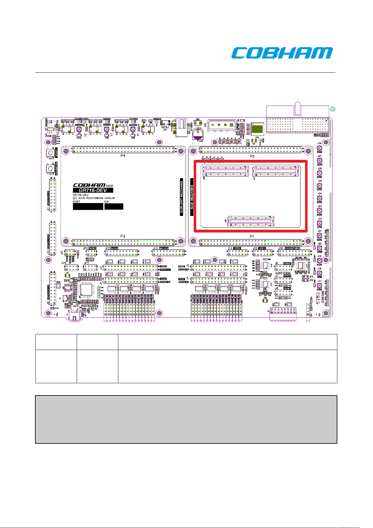
3.3 Plug-on configuration boards
To avoid misconfiguration and driver contamination the GR-CPCI-GR716-DEV development board
implements a simple scheme where the user can create custom plug-on boards to select connections
between the GR716 device and interface driver/source. The plug-on boards are refereed to as
GR716-CONFIG1 boards. This document describes 3 variants of the GR716-CONFIGx boards:
• Configx – This is the configuration which enables connection all to interface
drivers/receivers on the GR-CPCI-GR716-DEV Development board.
• Config0 – Enables GPIO, UART, MIL-1553, PacketWire, CAN, SPI Master and Slave,
SpaceWire and SPI4S over CMOS. Configuration also supports on-chip ADC and DAC
• Config1 – Enables GPIO, MIL-1553, CAN, SPI Slave, external SRAM/FLASH/SPI
memory, external ADC/DAC interface. Configuration also supports on-chip ADC and DAC.
Figure 1 View of the board after configuration board is installed
© Cobham Gaisler AB
Page 13
Doc. No: GR716-DEV-QSG
Issue: 0 Rev.: 2
Date: 2019-05-02 Page: 13 of 31
Status: Draft
Figure 2 GR-CPCI-GR716-DEV configuration board placements
Connector Default Description
P2 Config0 Enables GPIO, UART, MIL-1553, PacketWire, CAN, SPI Master and
Slave, SpaceWire and SPI4S over CMOS. Configuration also supports
on-chip ADC and DAC
Default configuration
Plugin a GR716-CONFIG1 board into connector P2
© Cobham Gaisler AB
Page 14

Doc. No: GR716-DEV-QSG
Issue: 0 Rev.: 2
Date: 2019-05-02 Page: 14 of 31
Status: Draft
3.4 Power Supply
A single supply with a +5V (minimum) / +14V (maximum) is required to power the board. All other
necessary voltages on the board are derived from this input using discrete Power circuits on the
board (DC/DC or Linear Regulators as appropriate).
Figure 3 GR-CPCI-GR716-DEV board power connector J32
3.4.1 CPCI power supply
The +12V and -12V can be supplied via the compact PCI style.
© Cobham Gaisler AB
ATTENTION!!
Do not exceed +14.5V at power supply input, as this may damage the
board.
Default configuration
Default power configuration for stand alone board is to use single with a +5V (minimum) /
+14V (maximum) connected to the J32 connector.
ATTENTION!!
You must not apply power to connetor J32 when board is plugged into
compact PCI rack.
Page 15

Doc. No: GR716-DEV-QSG
Issue: 0 Rev.: 2
Date: 2019-05-02 Page: 15 of 31
Status: Draft
3.5 Boot strap configurations
Bootstrap signals configure the chip on reset and are listed in section Bootstrap signals of GR716
Data sheet and User's Manual. All of these signals can be controlled via the front panel of the GRCPCI-GR716-DEV board via the SPDT DIP switch S1 position 1 to 8.
Figure 4 GR-CPCI-GR716-DEV board front panel and boot strap dip switch
The bootstrap signals controlled via SPDT DIP switch S1 position 1 to 8 have the following impact
on the system behaviour:
• Remote boot access (S1-8) enables remote access to the GR716 microcontroller after
initialization has been completed. Enable of remote access will force the processor to power
down after initialization.
• Disable use of internal boot ROM (S1-1) disables initialization of processor and internal
memories. If internal boot PROM is disabled the processor will start execute software
directly from selected source or power down after remote interface has been enabled.
• Disable internal memory test (S1-3) will make the system boot much faster but will not
check or initialize internal memories.
• Select boot source (S1-6, S1-7) will together with the remote boot access (S1-8) and switch
select boot source. Pin has dual functionality and is deepened upon boot strap configuration
with higher precedence
• Enable use of ASW (S1-5) enables CRC-16 checking of software from external SRAM,
PROM, SPI memory or I2C memory
• Enable use of redundant memory (S1-4). When ASW (S1-5) is enabled system can be
configured to start from redundant memory when an error occurs during start-up.
• EDAC for external memories (S1-2) enables error detection and correction for external
SRAM, PROM and SPI memory. When this bit is enabled system expects correction codes
to be stored together with application software.
• Enable PLL (S1-2) enables internal SpaceWire frequency generation using the internal PLL.
If disabled the internal PLL is bypassed is expected to be 50 MHz i.e. internal SpaceWire
frequency divisor is set to 5 to generate a 10 Mbit SpaceWire link.
• Select SpaceWire default frequency (S1-4, S1-5).
© Cobham Gaisler AB
Page 16

Doc. No: GR716-DEV-QSG
Issue: 0 Rev.: 2
Date: 2019-05-02 Page: 16 of 31
Status: Draft
© Cobham Gaisler AB
Default configuration
Default configuration is to start execute application software from the SPI memory after
internal ROM has been executed.
The default configuration of the board uses:
S1-1 Closed
S1-2 Closed
S1-3 Closed
S1-4 Closed
S1-5 Closed
S1-6 Closed
S1-7 Closed
S1-8 Closed
Page 17

Doc. No: GR716-DEV-QSG
Issue: 0 Rev.: 2
Date: 2019-05-02 Page: 17 of 31
Status: Draft
3.5.1 From external memory
This section lists external memory boot configurations i.e. when S1-8 is closed. Note that list only
includes valid configurations for the GR716 Development Board.
Table 1 Direct boot from external memory
S1 1
(EDAC)
S1 2
(Bypass ROM)
S1 3
(Disable test)
S1 4
(Redundant)
S1 5
(Copy ASW)
S1 6
(Source)
S1 7
(Source)
S1 8
(Remote)
Comment
Closed Open Don't care Closed** Closed Closed Closed Closed Boot direct from
external SPI memory
Closed Closed Closed Closed** Closed Closed Closed Closed Boot direct from
external SPI
memory after system
initialization and
memories has been
checked.
Closed Closed Open Closed** Closed Closed Closed Closed Boot direct from
external SPI memory
after system
initialization.
Open* Closed Closed Closed** Closed Closed Closed Closed Boot direct from
external SPI memory
with EDAC correction
enabled after system
initialization and
memories has been
checked.
Initialization.
Open* Closed Closed Closed** Open*** Closed Closed Closed Extract ASW
container from
external SPI memory
with EDAC correction
enabled after system
initialization and
memories has been
checked.
Initialization.
* Requires SPI PROM to be pre-programmed with correction codes
** Redundant SPI PROM requires additional board. Contact support@gaisler.com for more information.
*** Requires software to be stored using ASW format described in GR716 Datasheet
© Cobham Gaisler AB
Page 18

Doc. No: GR716-DEV-QSG
Issue: 0 Rev.: 2
Date: 2019-05-02 Page: 18 of 31
Status: Draft
3.5.2 Remote boot
This section lists external memory boot configurations i.e. when S1-8 is Open. Note that list only
includes valid configurations for the GR716 Development Board.
Table 2 Remote boot configurations for GR716 Development board
S1 1
(PLL)
S1 2
(Bypass ROM)
S1 3
(Disable test)
S1 4
(SpW Freq)
S1 5
(SpW Freq)
S1 6
(Source)
S1 7
(Source)
S1 8
(Remote)
Comment
Open Closed Closed Closed** Closed** Closed Closed Open Remote boot via
SpaceWire RMAP
using a crystal
oscillator of 25 MHz
Closed* Closed Closed Don't care Don't care Closed Closed Open Remote boot via
SpaceWire RMAP
using an external
frequency of 50 MHz
Don't care Closed Closed Don't care Don't care Open Closed Open Remote boot via SPI
Don't care Closed Closed Don't care Don't care Closed Open Open Remote boot via I2C
Don't care Closed Closed Don't care Don't care Open Open Open Remote boot via
UART
* Requires external SpaceWire clock at running 50 Mhz
** Possible to change crystal oscillator. See section 3.7
© Cobham Gaisler AB
Page 19

Doc. No: GR716-DEV-QSG
Issue: 0 Rev.: 2
Date: 2019-05-02 Page: 19 of 31
Status: Draft
3.6 Reset
The default configuration is to use the internal Power-On-Reset functionality. The length of the
reset is determined by the capacitor C19 on the GR716-BOARD.
3.6.1 External Reset and break switch
Reset switch, Break switch is provided on the front-panel.
Figure 5 Reset and Break switch on the GR-CPCI-GR716-DEV board front panel
© Cobham Gaisler AB
Default configuration
The default configuration is to use the internal Power-On-Reset functionality.
Page 20

Doc. No: GR716-DEV-QSG
Issue: 0 Rev.: 2
Date: 2019-05-02 Page: 20 of 31
Status: Draft
3.7 Clocking
The default configuration of the GR-CPCI-GR716-DEV board is to use the external 25 MHz crystal
oscillator Y1 (XTAL-DIL8_PCB) mounted on the GR716-BOARD as system and SpaceWire clock.
The GR716 device is designed to work with any crystal as long as the operating mode is of type
"Fundamental tone" and the frequency is in the range 4 MHz to 25 MHz. If SpaceWire is selected
as remote boot option design then external crystal oscillator frequency must be 5 MHz, 10 MHz, 20
MHz or 25 MHz.
The internal frequencies for ADC, DAC, MIL-1553, PackerWire, PWM, SPI4S, SpaceWire and
system depend upon the crystal oscillator frequency and on the internal clock logic and PLL
configuration. External system and SpaceWire clock source is selected with JP10 and JP11. If
SpaceWire is selected as remote boot option PLL should be configured via SPDT DIP switch S1
position 4 and 5.
Table 3 GR-CPCI-GR716-DEV clock configuration
Osclllitaor Frequency Mounted Comment
X2 Upto 50 MHz No No need to mount if clock is no used on GR716-
BOARD (Default configuration)
X3 Upto 100 MHz * No No need to mount if clock is no used on GR716-
BOARD (Default configuration)
X4 Upto 200 MHz No No need to mount if clock is no used on GR716-
BOARD (Default configuration)
* When SpaceWire is selected as remote boot option design then external crystal oscillator
frequency must be 5 MHz, 10 MHz, 20 MHz or 25 MHz.
© Cobham Gaisler AB
Default configuration
Default configuration is to clock distributed from the GR716-BOARD
Page 21

Doc. No: GR716-DEV-QSG
Issue: 0 Rev.: 2
Date: 2019-05-02 Page: 21 of 31
Status: Draft
3.8 Pin multiplexing
The GR716 shares memory and communication interface due to limited number of pins. See section
signal overview of the GR716 Data sheet and User’s manual.
There are a number things to take into consideration when configuring the pin multiplexing:
• Boot strap option might cause sub-sections of shared pins to be used for memories or remote
access
• GR716 Development board might be connected to hardware not aware of the GR716 e.g.
when user has mounted the GR716 Development board onto a GR-CPCI-GR716-DEV board
• GR716 configuration board used
Pin muxing configuration is set in the System IO configuration registers described in section
Configuration Registers in the GR716 Data sheet and User’s manual.
The the System IO configuration registers is updated after reset to reflect the system configuration.
E.g. if the system is configured to use external SRAM memory a number of System IO
configuration registers is set to the value 0x2 to select SRAM functionality for external pin.
It should be recommended to always read he System IO configuration registers before applying new
IO configuration to avoid misconfiguration of pins
For sanity check user can validate pin configuration using the validation script described in the
section I/O switch matrix pin validation script in the GR716 Data sheet and User’s manual. It
should be noted that the script can not verify every possible configuration.
© Cobham Gaisler AB
Page 22

Doc. No: GR716-DEV-QSG
Issue: 0 Rev.: 2
Date: 2019-05-02 Page: 22 of 31
Status: Draft
3.9 Pin properties
There are TBD KΩ pullup and pulldown resistor built in to the GR716 microcontroller that can be
accessed from software. These built-in resistors are accessed by setting pin mode to input-pullup or
input-pulldown mode.
3.10 Debug UART FTDI
The Debug UART interface is available via UART to USB conversion on the front-panel.
Figure 6 Reset and Break switch on the GR-CPCI-GR716-DEV board front panel
For information on the external FTDI debug interface see [RD2].
© Cobham Gaisler AB
ATTENTION!!
Pullup and pulldown resistor should only be enabled in input mode
Do NOT enable pullup and pulldown resistor in analog mode.
ATTENTION!!
Pullup and pulldown resistor should only be enabled in input mode
Do NOT enable pullup and pulldown resistor in analog mode.
ATTENTION!!
Pullup and pulldown resistor should only be enabled in input mode
Do NOT enable pullup and pulldown resistor in analog mode.
Page 23
Doc. No: GR716-DEV-QSG
Issue: 0 Rev.: 2
Date: 2019-05-02 Page: 23 of 31
Status: Draft
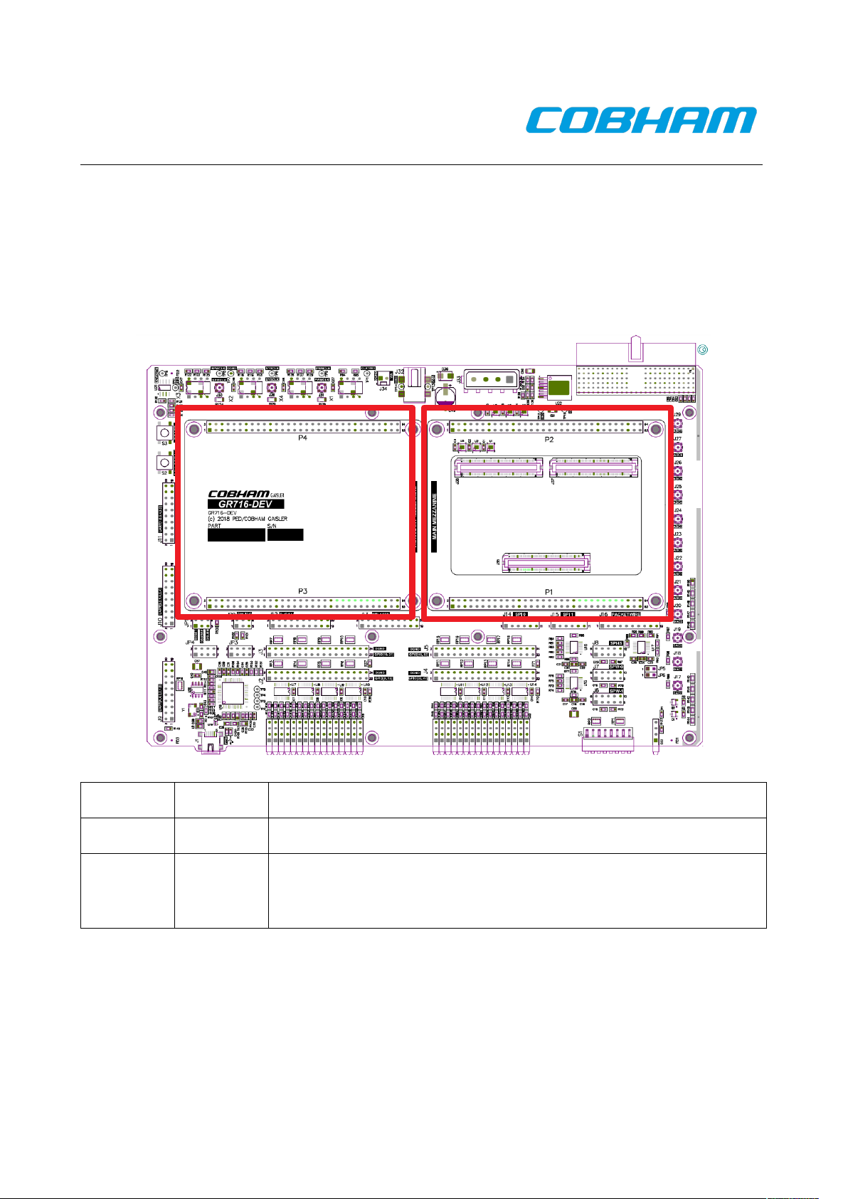
3.11 GR716-BOARD and Expansion Boards
This section describes how to install and the GR716-BOARD [RD2] and expansion boards on the
GR-CPCI-GR716-DEV board. The GR716-CPCI-DEV board provides two sites with two 2x32 pin
headers to allow the board to function as a carrier board for GR716-BOARD and Expansion
Boards.
Header Default Description
P1, P2 Intended for the GR716-BOARD
P3, P4 Alternative set of headers providing a convenient way for User
Defined interface boards to be developed and connected to the GR716CPCI-DEV board.
For more information for mounting GR716-BOARD and Expansion Boards see [RD2]
© Cobham Gaisler AB
Page 24

Doc. No: GR716-DEV-QSG
Issue: 0 Rev.: 2
Date: 2019-05-02 Page: 24 of 31
Status: Draft
4 SOFTWARE DEVELOPMENT ENVIRONMENT
4.1 Overview
Cobham Gaisler provides a comprehensive set of software tools to run several different operating
systems. The GR716 platform supports the following:
BCC Bare C Cross-Compiler System is a toolchain to compile bare C or C++ applications
directly on top of the processor without the servises provided by an operating system
Cobham Gaisler also provides a set of debug tools. The GR716 platform is supported by the
following:
GRMON Used to run and debug applications on GR716-BOARD hardware. See section 5
TSIM Used to run and debug applications on a simulated GR716-BOARD. See section X
TSIM is mainly used when no hardware is available. However, TSIM also provides faster than
realtime simulation and can be integrated into larger simulation networks to simulate, for example,
entire satellite systems. TSIM provides precise code coverage capture and large instruction/bus
trace buffers.
Developer tools are generally provided for both Linux and Windows host operating systems.
Cobham Gaisler also provides an integrated, easy-to-use solution to help programmers with the task
of developing for the LEON. The LEON Integrated Development Environment for Eclipse (LIDE)
is an Eclipse plug-in integrating compilers, software and hardware debuggers in a graphical user
interface. The plugin makes it possible to cross-compile C and C++ application for LEON, and to
debug them on either simulator and target hardware (TSIM or GRMON).
The recommended method to load software onto a LEON board is by connecting to a debug
interface of the board through the GRMON hardware debugger in chapter 5.
© Cobham Gaisler AB
Page 25

Doc. No: GR716-DEV-QSG
Issue: 0 Rev.: 2
Date: 2019-05-02 Page: 25 of 31
Status: Draft
5 GRMON HARDWARE DEBUGGER
5.1 Overview
GRMON3 is a debug monitor used to develop and debug GRLIB/LEON systems. The CPU and its
peripherals are accessed on the AMBA bus through a debug-link connected to the PC. GRMON3
has GDB support which makes C/C++ level debugging possible by connecting GDB to the
GRMON3's GDB socket. With GRMON3 one can for example:
• Inspect LEON and peripheral registers
• Upload applications to RAM with the load command
• Program the FLASH with the flash command
• Control execution flow by starting applications (run), continue execution (cont), single-
stepping (step), inserting breakpoints/watchpoints (bp) etc.
• Inspect the current CPU state listing the back-trace, instruction trace and disassemble
machine code.
The first step is to set up a debug link in order to connect to the board. The following section
outlines which debug interfaces are available and how to use them on the GR716 Development
Board, after that a basic first inspection of the board is exemplified.
Several of the SoC's peripherals may be clock gated off. GRMON will enable all clocks if started
with the flag - cginit. Within GRMON, the command grcg enable all will have the same effect.
GRMON3 is described on the homepage [http://www.gaisler.com/index.php/products/debug-tools]
and in detail in [RD4].
5.2 Debug-link alternatives
5.2.1 Connecting via the FTDI USB/UART interface
Please see Section 3.10 to configure FTDI interface. Please see GRMON User's Manual for how to
set up the required FTDI driver software. Then connect the PC and the board using a standard USB
cable into the FTDI USB connector and issue the following command:
grmon -uart /dev/ttyUSB0
It is recommended to use the GRMON command line option -baud 230400 to increase the
AHBUART debug link speed.
5.2.2 Connecting via SpaceWire RAMP interfaces
GRMON2 has support for connecting to boards with SpaceWire interfaces as long as the SpaceWire
has RMAP and automatic link start. An Ethernet to SpaceWire bridge (GRESB) is required to
tunnel SpaceWire packets from the Ethernet network over to SpaceWire.
© Cobham Gaisler AB
Page 26

Doc. No: GR716-DEV-QSG
Issue: 0 Rev.: 2
Date: 2019-05-02 Page: 26 of 31
Status: Draft
Figure 7 Connecting via SpaceWire RAMP requires external hardware e.g. GRESB to
convert Ethernet to SpaceWire RMAP packets
Please see the Error: Reference source not found for more information about connecting through a
GRESB and optional parameters. Connect the GRESB SpW0 connector and the GR716 SpaceWire
connector on the frontpanel, then issue the following command:
grmon -gresb
5.3 First steps
The previous sections have described which debug-links are available and how to start using them
with GRMON3. The subsections below assume that GRMON3, the host computer and the GRGR716 board have been set up so that GRMON3 can connect to the board.
When connecting to the board for the first time it is recommended to get to know the system by
inspecting the current configuration and hardware present using GRMON3. With the info sys
command more details about the system is printed and with info reg the register contents of the I/O
registers can be inspected. Below is a list of items of particular interest:
• AMBA system frequency is printed out at connect, if the frequency is wrong then it might
be due to noise in auto detection (small error). See -freq flag in [RD4].
• Memory location and size configuration is found from the info sys output.
• The GR716 has a clock-gating unit which is able to disable/enable clocking and control reset
signals. Clocks must be enabled for all cores that LEON software or GRMON3 will be
using. The grcg command is described in [RD4].
5.4 Connecting to the board
The transcript below shows an example session with GRMON3. GRMON3is started with the -u
flag in order to redirect UART output to the GRMON2 terminal.
© Cobham Gaisler AB
Page 27

Doc. No: GR716-DEV-QSG
Issue: 0 Rev.: 2
Date: 2019-05-02 Page: 27 of 31
Status: Draft
cg@hwlin0:~$ grmon3 -u -cginit 0x10000 -uart /dev/ttyUSB0
GRMON LEON debug monitor v3.0.12-89-ga1d42ef 64-bit internal version
Copyright (C) 2018 Cobham Gaisler - All rights reserved.
For latest updates, go to http://www.gaisler.com/
Comments or bug-reports to support@gaisler.com
This internal version will expire on 12/05/2019
Parsing -u
Parsing -uart /dev/ttyUSB0
using port /dev/ttyUSB0 @ 115200 baud
Device ID: 0x716
GRLIB build version: 4204
Detected system: GR716
Detected frequency: 25 MHz
Component Vendor
AHB-to-AHB Bridge Cobham Gaisler
MIL-STD-1553B Interface Cobham Gaisler
GRSPW2 SpaceWire Serial Link Cobham Gaisler
SPI to AHB Bridge Cobham Gaisler
I2C to AHB Bridge Cobham Gaisler
CAN Controller with DMA Cobham Gaisler
CAN Controller with DMA Cobham Gaisler
AHB Debug UART Cobham Gaisler
AHB-to-AHB Bridge Cobham Gaisler
PacketWire Receiver with DMA Cobham Gaisler
PacketWire Transmitter with DMA Cobham Gaisler
GRDMAC DMA Controller Cobham Gaisler
GRDMAC DMA Controller Cobham Gaisler
GRDMAC DMA Controller Cobham Gaisler
GRDMAC DMA Controller Cobham Gaisler
Dual-port SPI Slave Cobham Gaisler
LEON3FT SPARC V8 Processor Cobham Gaisler
AHB-to-AHB Bridge Cobham Gaisler
AHB Memory Scrubber Cobham Gaisler
AHB-to-AHB Bridge Cobham Gaisler
AHB Debug UART Cobham Gaisler
Dual-port AHB(/CPU) On-Chip RAM Cobham Gaisler
Dual-port AHB(/CPU) On-Chip RAM Cobham Gaisler
Generic AHB ROM Cobham Gaisler
Memory controller with EDAC Cobham Gaisler
SPI Memory Controller Cobham Gaisler
SPI Memory Controller Cobham Gaisler
AHB/APB Bridge Cobham Gaisler
AHB/APB Bridge Cobham Gaisler
AHB/APB Bridge Cobham Gaisler
AHB/APB Bridge Cobham Gaisler
Memory controller with EDAC Cobham Gaisler
LEON3 Debug Support Unit Cobham Gaisler
AHB/APB Bridge Cobham Gaisler
AMBA Trace Buffer Cobham Gaisler
Multi-processor Interrupt Ctrl. Cobham Gaisler
Modular Timer Unit Cobham Gaisler
Modular Timer Unit Cobham Gaisler
GR716 AMBA Protection unit Cobham Gaisler
Clock gating unit Cobham Gaisler
Clock gating unit Cobham Gaisler
General Purpose Register Cobham Gaisler
LEON3 Statistics Unit Cobham Gaisler
AHB Status Register Cobham Gaisler
CCSDS TDP / SpaceWire I/F Cobham Gaisler
General Purpose Register Bank Cobham Gaisler
© Cobham Gaisler AB
Page 28

Doc. No: GR716-DEV-QSG
Issue: 0 Rev.: 2
Date: 2019-05-02 Page: 28 of 31
Status: Draft
General Purpose Register Cobham Gaisler
GR716 AMBA Protection unit Cobham Gaisler
GR716 Bandgap Cobham Gaisler
GR716 Brownout detector Cobham Gaisler
GR716 Phase-locked loop Cobham Gaisler
Generic UART Cobham Gaisler
Generic UART Cobham Gaisler
Generic UART Cobham Gaisler
Generic UART Cobham Gaisler
Generic UART Cobham Gaisler
Generic UART Cobham Gaisler
AHB Status Register Cobham Gaisler
ADC / DAC Interface Cobham Gaisler
SPI Controller Cobham Gaisler
SPI Controller Cobham Gaisler
PWM generator Cobham Gaisler
General Purpose I/O port Cobham Gaisler
General Purpose I/O port Cobham Gaisler
AMBA Wrapper for OC I2C-master Cobham Gaisler
AMBA Wrapper for OC I2C-master Cobham Gaisler
GR716 Analog-to-Digital Conv Cobham Gaisler
GR716 Analog-to-Digital Conv Cobham Gaisler
GR716 Analog-to-Digital Conv Cobham Gaisler
GR716 Analog-to-Digital Conv Cobham Gaisler
GR716 Analog-to-Digital Conv Cobham Gaisler
GR716 Analog-to-Digital Conv Cobham Gaisler
GR716 Analog-to-Digital Conv Cobham Gaisler
GR716 Analog-to-Digital Conv Cobham Gaisler
GR716 Digital-to-Analog Conv Cobham Gaisler
GR716 Digital-to-Analog Conv Cobham Gaisler
GR716 Digital-to-Analog Conv Cobham Gaisler
GR716 Digital-to-Analog Conv Cobham Gaisler
I2C Slave Cobham Gaisler
I2C Slave Cobham Gaisler
PWM generator Cobham Gaisler
LEON3 Statistics Unit Cobham Gaisler
General Purpose Register Cobham Gaisler
Use command 'info sys' to print a detailed report of attached cores
grmon3>
© Cobham Gaisler AB
Page 29

Doc. No: GR716-DEV-QSG
Issue: 0 Rev.: 2
Date: 2019-05-02 Page: 29 of 31
Status: Draft
6 TSIM LEON SIMULATOR
Emulation and simulation is described in section 6 in [RD3]
7 TOOLCHAINS
The Bare C Cross-Compiler (BCC for short) is described in section 7 in [RD3]
8 SOFTWARE EXAMPLES
Software examples is provided with the GR716-CPCI-DEV board and is described in section 8 in
[RD3]
9 EXPANSION BOARDS
List of compatible expansion and interface boards:
• GR-CPCI-6U-UART
• GR-CPCI-GR740
• GR-CPCI-CAN
• GR-CPCI-RS422
• GR-CPCI-RS422
• GR-TMTC-PW
• GR716-TEST-MEM
• GR716-BOARD
For more information see [RD2] or visit www.gailser.com
10 SUPPORT
For support contact the Cobham Gaisler support team at support@gaisler.com.
When contacting support, please identify yourself in full, including company affiliation and site
name and address. Please identify exactly what product that is used, specifying if it is an IP core
(with full name of the library distribution archive file), component, software version, compiler
version, operating system version, debug tool version, simulator tool version, board version, etc.
The support service is only for paying customers with a support contract.
© Cobham Gaisler AB
Page 30

Doc. No: GR716-DEV-QSG
Issue: 0 Rev.: 2
Date: 2019-05-02 Page: 30 of 31
Status: Draft
11 APPENDIX A
Figure 8 Board assembly drawing
© Cobham Gaisler AB
Page 31

Doc. No: GR716-DEV-QSG
Issue: 0 Rev.: 2
Date: 2019-05-02 Page: 31 of 31
Status: Draft
Cobham Gaisler AB
Kungsgatan 12
411 19 Gothenburg
Sweden
www.cobham.com/gaisler
sales@gaisler.com
T: +46 31 7758650
F: +46 31 421407
Cobham Gaisler AB, reserves the right to make changes to any products and services described
herein at any time without notice. Consult Cobham or an authorized sales representative to verify
that the information in this document is current before using this product. Cobham does not assume
any responsibility or liability arising out of the application or use of any product or service
described herein, except as expressly agreed to in writing by Cobham; nor does the purchase, lease,
or use of a product or service from Cobham convey a license under any patent rights, copyrights,
trademark rights, or any other of the intellectual rights of Cobham or of third parties. All
information is provided as is. There is no warranty that it is correct or suitable for any purpose,
neither implicit nor explicit.
Copyright © 2019 Cobham Gaisler.
© Cobham Gaisler AB
 Loading...