

Cobham Wireless - Coverage
BSF0060 User Handbook
www.cobham.com/wireless
Document number: BSF0060HBK
Issue number: 4
Date: 12/12/2016
Page 1 of 43
The most important thing we build is trust
BSF0060
User Handbook
Band-Selective, Class B, Fibre-Fed Repeater
User Handbook
Product Part No. BSF0060
BSF3604-406-411-115VAC

Cobham Wireless - Coverage
BSF0060 User Handbook
www.cobham.com/wireless
Document number: BSF0060HBK
Issue number: 5
Date: 14/05/2018
Page 2 of 43
Table of Contents
1. Introduction ......................................................................................................................... 4
1.1. Scope and Purpose of Document ...................................................................................... 4
1.2. Limitation of Liability Notice ............................................................................................. 4
1.3. Copyright Notice .............................................................................................................. 5
1.4. Contact Information ......................................................................................................... 5
1.5. Compliance with IC .......................................................................................................... 6
1.6. Compliance with FCC ....................................................................................................... 7
1.6.1. FCC Part 15 .............................................................................................................. 7
1.6.2. Unauthorized Changes to Equipment .......................................................................... 7
1.6.3. FCC RF Exposure Limits ............................................................................................. 7
1.6.4. Antenna Installation .................................................................................................. 8
1.6.5. Compliance with FCC deployment rule regarding the radiation of noise ........................ 8
2. Safety Notices .................................................................................................................... 10
2.1. Earthing of Equipment ................................................................................................... 10
2.2. Electric Shock Hazard ..................................................................................................... 10
2.3. RF Radiation Hazard ...................................................................................................... 10
2.4. Lifting and other Health and Safety Recommendations..................................................... 10
2.5. Chemical Hazard ............................................................................................................ 11
2.6. Laser Safety .................................................................................................................. 11
2.7. Emergency Contact Numbers ......................................................................................... 11
3. BSF3604-406-411-115VAC - BSF0060 .................................................................................. 12
3.1. Automatic Level Control ................................................................................................. 13
3.2. BSF0060 Major Sub Components .................................................................................... 14
3.3. BSF0060 Specification .................................................................................................... 14
3.4. BSF0060 System Diagram .............................................................................................. 15
3.5. BSF0060 External and Internal Views .............................................................................. 16
3.5.1. External view .......................................................................................................... 16
3.5.2. External Interfaces .................................................................................................. 17
3.5.3. Internal Features .................................................................................................... 18
3.6. Internal Modules ........................................................................................................... 19
3.6.1. Control Module ....................................................................................................... 19
3.6.2. Fibre Optic Transceiver Module ................................................................................ 20
3.6.3. PSU Module ............................................................................................................ 21
3.6.4. External Interface Board, Cable and Terminal Block .................................................. 22
3.6.5. Digital Signal Processing (DSP) module .................................................................... 23
3.6.6. Multi Carrier Power Amplifier (MCPA) ....................................................................... 23
3.6.7. Bandpass Duplexer Module ...................................................................................... 23
3.6.8. Reference Generator Board ..................................................................................... 23
3.6.9. Distribution Board ................................................................................................... 23
4. Antenna and Repeater Installation Requirements .................................................................. 24
4.1. BSF0060 Installation Requirements ................................................................................. 24
4.1.1. Safety Guidelines .................................................................................................... 24
4.1.2. Criteria for Repeater Installation Location ................................................................. 24
4.1.3. RF Cable Installation Guidelines ............................................................................... 25
4.1.4. F/O Cable Installation Guidelines .............................................................................. 25
4.2. Service Antenna Requirements ....................................................................................... 25
4.2.1. Required Antenna Information ................................................................................. 25
4.2.2. Indoor Installations ................................................................................................. 26
4.2.2.1. Recommended Antennas ...................................................................................... 26
4.2.2.2. Recommended Splitters and Couplers ................................................................... 26
4.2.2.3. Installation Criteria .............................................................................................. 27
4.2.2.4. Service (Mobile) Antenna Installation Criteria ........................................................ 27

Cobham Wireless - Coverage
BSF0060 User Handbook
www.cobham.com/wireless
Document number: BSF0060HBK
Issue number: 5
Date: 14/05/2018
Page 3 of 43
4.3. RF Cabling Requirements ............................................................................................... 27
5. Repeater Installation ........................................................................................................... 28
5.1. Location Criteria ............................................................................................................ 28
5.2. Unpacking ..................................................................................................................... 29
5.3. Bracket Assembly .......................................................................................................... 30
5.4. Mounting the Repeater onto a Wall ................................................................................. 32
6. Initial Setup ........................................................................................................................ 34
6.1. Opening an RMC Session ............................................................................................... 34
6.2. User Access ................................................................................................................... 36
6.3. Define Repeater General Info ......................................................................................... 36
6.4. Configuring RF Parameters ............................................................................................. 37
6.5. Configuring External Alarms and Relay ............................................................................ 39
6.5.1. Configuring External Alarms ..................................................................................... 39
6.5.2. Configuring and Testing the Relay............................................................................ 40
6.6. TCP/IP Communication Configuration – for Remote Monitoring ......................................... 40
6.7. Integration into the AEM ................................................................................................ 41
Appendix .................................................................................................................................... 42
A.1. Glossary of Terms used in this document ........................................................................ 42
A.2. Document Amendment Record ....................................................................................... 43

Cobham Wireless - Coverage
BSF0060 User Handbook
www.cobham.com/wireless
Document number: BSF0060HBK
Issue number: 5
Date: 14/05/2018
Page 4 of 43
1. Introduction
1.1. Scope and Purpose of Document
This handbook is for use solely with the equipment identified by the Cobham Wireless Part Number(s)
shown on the front page. It is not to be used with any other equipment unless specifically authorised
by Cobham Wireless. This is a controlled release document and, as such, becomes a part of the
Cobham Wireless Total Quality Management System. Alterations and modification may therefore only
be performed by Cobham Wireless.
Cobham Wireless recommends that the installer of this equipment familiarise themselves with all of
the safety notices and any installation procedures contained within this document before installation
commences.
The purpose of this handbook is to provide the user/maintainer with a general overview of the
equipment and its functions along with basic fault-finding and troubleshooting procedures where
appropriate. Maintenance and adjustments to any deeper level must be performed by Cobham
Wireless, normally at the company’s repair facility in Chesham, England.
This handbook has been prepared in accordance with Cobham Wireless’ Quality procedures, which
maintain the company’s registration to BS EN ISO 9001:2008 and to the R&TTE Directive of the
European Parliament. Copies of the relevant certificates and the company Quality Manual can be
supplied on application.
1.2. Limitation of Liability Notice
This manual is written for the use of technically competent operators/service persons. No liability is
accepted by Cobham Wireless for use or misuse of this manual, the information contained therein, or
the consequences of any actions resulting from the use of the said information, including, but not
limited to, descriptive, procedural, typographical, arithmetical, or listing errors. Furthermore, Cobham
Wireless does not warrant the absolute accuracy of the information contained within this manual, or
its completeness, fitness for purpose, or scope.
Cobham Wireless has made every effort to ensure that the instructions contained in this document
are adequate and free of errors and omissions. The manufacturer will, if necessary, explain issues
which may not be covered by this document. The manufacturer's liability for any errors in the
document is limited to the correction of errors and the aforementioned advisory services.
Cobham Wireless has a policy of continuous product development and enhancement, and as such,
reserves the right to amend, alter, update and generally change the contents, appearance and
pertinence of this document without notice. Cobham Wireless welcomes customer comments as part
of the process of continual development and improvement of the documentation in the best way
possible from the user's viewpoint. Please submit your comments to the nearest Cobham Wireless
sales representative.
Unless specified otherwise, all Cobham Wireless products carry a twelve month warranty from date of
shipment. The warranty is expressly on a return-to-base repair or exchange basis and the warranty
cover does not extend to on-site repair or complete unit exchange.

Cobham Wireless - Coverage
BSF0060 User Handbook
www.cobham.com/wireless
Document number: BSF0060HBK
Issue number: 5
Date: 14/05/2018
Page 5 of 43
1.3. Copyright Notice
Copyright © 2015 Cobham Wireless. All rights reserved. No part of this document may be copied,
distributed, transmitted, transcribed, stored in a retrieval system, or translated into any human or
computer language without the prior written permission of Cobham Wireless.
1.4. Contact Information
Cobham Wireless (Coverage)
Aerial House, Asheridge Road
Chesham, Buckinghamshire
HP5 2QD, United Kingdom
Tel: +44 1494 777000 Fax: +44 1494 777002
Commercial inquiries cw.coverage@cobham.com
Website www.cobham.com/wireless
Support issues cw.support@cobham.com
Technical Support Line, +44 1494 777 747
English speaking
Registered Office:
Axell Wireless Limited trading as Cobham Wireless
Registered Office: C/O Cobham plc, Brook Road, Wimborne, Dorset, BH21 2BJ, UK
Registered in England and Wales: 04042808
www.cobham.com/wireless

Cobham Wireless - Coverage
BSF0060 User Handbook
www.cobham.com/wireless
Document number: BSF0060HBK
Issue number: 5
Date: 14/05/2018
Page 6 of 43
1.5. Compliance with ISED
WARNING: This is NOT a CONSUMER device.
It is designed for installation by an installer approved
by an ISED licensee. You MUST have an ISED LICENCE or
the express consent of an
ISED licensee to operate this device.
Under Innovation, Science and Economic Development (ISED) Canada regulations, this radio
transmitter may only operate using an antenna of a type and maximum (or lesser) gain approved for
the transmitter by Industry Canada. To reduce potential radio interference to other users, the
antenna type and its gain should be so chosen that the equivalent isotropically radiated power
(e.i.r.p.) is not more than that necessary for successful communication.
The Manufacturer's rated output power of this equipment is for single carrier operation. For situations
when multiple carrier signals are present, the rating would have to be reduced by 3.5 dB, especially
where the output signal is re-radiated and can cause interference to adjacent band users. This power
reduction is to be by means of input power or gain reduction and not by an attenuator at the output
of the device.
This equipment complies with ISED RSS-102 radiation exposure limits set forth for an uncontrolled
environment. This equipment should be installed and operated with minimum distance of 2.15 m
between the antenna and your body,
The installation procedure must result in the signal booster complying with ISED requirements RSS131 Clause 6.3 and 6.4. In order to meet ISED requirements RSS-131 Clause 6.3 and 6.4, it may be
necessary for the installer to reduce the UL and/or DL output power for certain installations.
Conformément à la réglementation d'Innovation, Sciences et Développement Économique (ISDE)
Canada, le présent émetteur radio peut fonctionner avec une antenne d'un type et d'un gain maximal
(ou inférieur) approuvé pour l'émetteur par Industrie Canada. Dans le but de réduire les risques de
brouillage radioélectrique à l'intention des autres utilisateurs, il faut choisir le type d'antenne et son
gain de sorte que la puissance isotrope rayonnée équivalente (p.i.r.e.) ne dépasse pas l'intensité
nécessaire à l'établissement d'une communication satisfaisante.
La puissance de sortie nominale indiquée par le fabricant pour cet appareil concerne son
fonctionnement avec porteuse unique. Pour des appareils avec porteuses multiples, on doit réduire la
valeur nominale de 3.5dB, surtout si le signal de sortie est retransmis et qu'il peut causer du
brouillage aux utilisateurs de bandes adjacentes. Une telle réduction doit porter sur la puissance
d'entrée ou sur le gain, et ne doit pas se faire au moyen d'un atténuateur raccordé à la sortie du
dispositif.
Cet appareil est conforme aux limitations de la norme ISDE RSS-102 concernant l’exposition aux
radiations dans un environnement non contrôlé. Cet appareil doit être installé et utilisé avec une
distance minimale de 2.15 m entre l’antenne et le corps de l’utilisateur.
La procédure d'installation doit permettre à l'amplificateur de signal de se conformer aux exigences
ISDE RSS-131 Clause 6.3 et 6.4. Afin de respecter les exigences de la norme ISDE RSS-131,
paragraphes 6.3 et 6.4, il peut être nécessaire que l'installateur réduise la puissance de sortie UL et /
ou DL pour certaines installations.
Cobham Wireless - Coverage
BSF0060 User Handbook
www.cobham.com/wireless
Document number: BSF0060HBK
Issue number: 5
Date: 14/05/2018
Page 7 of 43
1.6. Compliance with FCC
Part 90 Signal Boosters THIS IS A 90.219 CLASS B DEVICE
WARNING: This is NOT a CONSUMER device. This device is designed for installation
by FCC LICENCEES and QUALIFIED INSTALLERS. You MUST have an FCC
LICENCE or express consent of an FCC Licensee to operate this device.
You MUST register Class B signal boosters (as defined in 47 CFR 90.219) online at
www.fcc.gov/signal-boosters/registration.
Unauthorized use may result in significant forfeiture penalties, including penalties in
excess of $100,000 for each continuing violation.
The installation procedure must result in the signal booster complying with FCC
requirements 90.219(d). In order to meet FCC requirements 90.219 (d), it may be
necessary for the installer to reduce the UL and/or DL output power for certain
installations.
1.6.1. FCC Part 15
This device complies with part 15 of the FCC Rules. Operation is subject to the following two
conditions:
1. This device may not cause harmful interference, and
2. This device must accept any interference received, including interference that may cause
undesired operation.
If not installed and used in accordance with the instructions, this equipment generates, uses and can
radiate radio frequency energy. However, there is no guarantee that interference will not occur in a
particular installation. If this equipment does cause harmful interference to RF reception, which can
be determined by turning the equipment off and on, the user is encouraged to try to correct the
interference by one or more of the following measures:
● Reorient or relocate the Donor antenna.
● Increase the separation between the equipment and receiver.
● Connect the equipment into a power outlet on a circuit different from that to which the
receiver is connected.
1.6.2. Unauthorized Changes to Equipment
Changes or Modifications not expressly approved by the manufacturer responsible for compliance
could void the user’s authority to operate the equipment
1.6.3. FCC RF Exposure Limits
This unit complies with FCC RF exposure limits for an uncontrolled environment. This equipment can
only be installed for applications, driving passive or active DAS systems. All antennas must be
operated at a minimum distance of 50 cm between the radiator and any person’s body.
Cobham Wireless - Coverage
BSF0060 User Handbook
www.cobham.com/wireless
Document number: BSF0060HBK
Issue number: 5
Date: 14/05/2018
Page 8 of 43
1.6.4. Antenna Installation
Installation of an antenna must comply with the FCC RF exposure requirements. The antenna used
for this transmitter must be mounted on permanent structures.
The FCC regulations mandate that the ERP of type B signal boosters should not exceed 5W, this is
equivalent to 8.2W EIRP.
Therefore the max antenna gain allowed for this type of signal booster should be limited to the values
given by equation 1 (below) for the service antenna.
Equation (1) - Max SERVICE antenna gain
Max SERVICE antenna gain (dBi) = 39.1 – (37dBm - # of antennas in dB – cable losses in dB).
For example:
No. of Antennas
Cable Losses
Max Allowed Antenna Gain
4
3
39.1 - (37-6-3) =11.1dBi
1
3
39.1- (37-0-3) = 5.1dbi
10
3
39.1- (37-10-3) = 15.1dbi
1.6.5. Compliance with FCC deployment rule regarding the radiation of noise
Good engineering practice must be used in regard to the signal booster’s noise radiation. Thus, the
gain of the signal booster should be set so that the ERP of the output noise from the signal booster
should not exceed the level of -43 dBm in 10 kHz measurement bandwidth.
In the event that the noise level measured exceeds the aforementioned value, the signal booster gain
should be decreased accordingly.
In general, the ERP of noise on a spectrum more than 1 MHz outside of the pass band should not
exceed -70 dBm in a 10 kHz measurement bandwidth.
The BSF0060 Repeater has a noise level of -66 dBm in 10 kHz measurement at 1 MHz spectrum
outside the passband of the signal booster and an in-band noise level at around -46 dBm in a 10 kHz
bandwidth. Therefore, the noise at the antenna input port should be calculated based on equation
(2).
Equation (2) - Input Noise to service antenna
Input Noise to service antenna:
-66 dBm – Antenna splitter losses in dB – cable loss in dB

Cobham Wireless - Coverage
BSF0060 User Handbook
www.cobham.com/wireless
Document number: BSF0060HBK
Issue number: 5
Date: 14/05/2018
Page 9 of 43
Example: In band Noise
Signal booster connected to 10 service antennas with a 100m long ½ inch cable.
Losses of such a cable with the connectors = ~ 12dB
Assuming 10 service antennas: antenna splitter losses = 11 dB
Based on equation (2) Input antenna noise (to the antenna) = -46-12 -11=-69 dBm ERP
The in-band input noise to the antenna should be -46 -12-11= -69dbm ERP
Example: Out of band noise
Signal booster connected to 10 service antennas with a 100m long ½ inch cable.
Losses of such a cable with the connectors = ~ 12dB
Assuming 10 service antennas: antenna splitter losses = 11 dB
Based on equation (2) Input antenna noise (to the antenna) = -66 -12 -11=-89dBm ERP
The Out of-band input noise to the antenna should be -66 -12-11= -89dbm ERP
NOTE: In this example there is no need to add an external band pass filter to attenuate the out of
band noise. If fewer antennas are deployed then additional filtering may be required
Conclusion:
Good engineering practice requires that in general when the out of band noise measured at the
service antenna input is more than -70 dBm per 10 kHz measurement bandwidth, an external band
pass filter should be added to attenuate the out of band noise level.
All Cobham Wireless repeaters include high selectivity duplexers and filters to attenuate the out of
band noise. Should additional filtering be required, we have a comprehensive range of interference
filters which can be supplied upon request.
Cobham Wireless - Coverage
BSF0060 User Handbook
www.cobham.com/wireless
Document number: BSF0060HBK
Issue number: 5
Date: 14/05/2018
Page 10 of 43
2. Safety Notices
2.1. Earthing of Equipment
Equipment supplied from the mains must be connected to grounded outlets and earthed
in conformity with appropriate local, national and international electricity supply and
safety regulations.
2.2. Electric Shock Hazard
The risk of electrical shocks due to faulty mains driven power supplies whilst
potentially ever present in any electrical equipment, would be minimised by adherence
to good installation practice and thorough testing at the following stages:
a) Original assembly.
b) Commissioning.
c) Regular intervals, thereafter.
All test equipment must be in good working order prior to its use. High current power supplies can be
dangerous because of the possibility of substantial arcing. Always switch off during disconnection and
reconnection.
2.3. RF Radiation Hazard
RF radiation, (especially at UHF frequencies) arising from transmitter outputs
connected to Cobham Wireless equipment, must be considered a safety hazard.
This condition might only occur in the event of cable disconnection, or because a
‘spare’ output has been left un-terminated. Either of these conditions would impair the
system’s efficiency. No investigation should be carried out until all RF power sources have been
removed. This would always be a wise precaution, despite the severe mismatch between the
impedance of an N type connector at 50Ω, and that of free space at 377Ω, which would severely
compromise the efficient radiation of RF power. Radio frequency burns could also be a hazard, if any
RF power carrying components were to be carelessly touched!
Antenna positions should be chosen to comply with requirements (both local & statutory) regarding
exposure of personnel to RF radiation. When connected to an antenna, the unit is capable of
producing RF field strengths, which may exceed guideline safe values especially if used with antennas
having appreciable gain. In this regard the use of directional antennas with backscreens and a strict
site rule that personnel must remain behind the screen while the RF power is on, is strongly
recommended. Where the equipment is used near power lines or in association with temporary masts
not having lightning protection, the use of a safety earth connected to the case-earthing bolt is
strongly advised.
2.4. Lifting and other Health and Safety Recommendations
Certain items of Cobham Wireless equipment are heavy and care should be taken
when lifting them by hand. Ensure that a suitable number of personnel, appropriate
lifting apparatus and appropriate personal protective equipment is used especially
when installing Equipment above ground e.g. on a mast or pole and manual handling
precautions relevant to items of the weight of the equipment being worked on must
be observed at all times when handling, installing or dismounting this equipment.
Cobham Wireless - Coverage
BSF0060 User Handbook
www.cobham.com/wireless
Document number: BSF0060HBK
Issue number: 5
Date: 14/05/2018
Page 11 of 43
2.5. Chemical Hazard
Beryllium Oxide, also known as Beryllium Monoxide, or Thermalox™, is sometimes
used in devices within equipment produced by Cobham Wireless. Beryllium oxide dust
can be toxic if inhaled, leading to chronic respiratory problems. It is harmless if
ingested or by contact.
Products that contain beryllium are load terminations (dummy loads) and some power amplifiers.
These products can be identified by a yellow and black “skull and crossbones” danger symbol (shown
above). They are marked as hazardous in line with international regulations, but pose no threat under
normal circumstances. Only if a component containing beryllium oxide has suffered catastrophic
failure, or exploded, will there be any danger of the formation of dust. Any dust that has been
created will be contained within the equipment module as long as the module remains sealed. For
this reason, any module carrying the yellow and black danger sign should not be opened. If the
equipment is suspected of failure, or is at the end of its life-cycle, it must be returned to Cobham
Wireless Ltd. for disposal.
To return such equipment, please contact the Support Desk, who will give you a Returned Materials
Authorisation (RMA) number. Please quote this number on the packing documents, and on all
correspondence relating to the shipment.
Polytetrafluoroethylene, (P.T.F.E.) and P.T.F.E. Composite Materials
Many modules/components in Cobham Wireless equipment contain P.T.F.E. as part of the RF
insulation barrier.
This material should never be heated to the point where smoke or fumes are evolved. Any person
feeling drowsy after coming into contact with P.T.F.E., especially dust or fumes should seek medical
attention.
2.6. Laser Safety
General good working practices adapted from EN60825-2: 2004/ EC 60825-2:2004
Do not stare with unprotected eyes or with any unapproved optical device at the fibre
ends or connector faces or point them at other people, Use only approved filtered or
attenuating viewing aids.
Any single or multiple fibre end or ends found not to be terminated (for example, matched, spliced)
shall be individually or collectively covered when not being worked on. They shall not be readily
visible and sharp ends shall not be exposed.
When using test cords, the optical power source shall be the last connected and the first
disconnected; use only approved methods for cleaning and preparing optical fibres and optical
connectors.
Always keep optical connectors covered to avoid physical damage and do not allow any dirt/foreign
material ingress on the optical connector bulkheads.
The optical fibre jumper cable minimum bend radius is 3cm; bending to a smaller radius may result in
optical cable breakage and excessive transmission losses.
Caution: The FO units are NOT weather proof.
2.7. Emergency Contact Numbers
The Cobham Wireless Support Desk can be contacted on:
Telephone +44 (0)1494 777747
Fax. +44 (0)1494 777002
e-mail cw.support@cobham.com

Cobham Wireless - Coverage
BSF0060 User Handbook
www.cobham.com/wireless
Document number: BSF0060HBK
Issue number: 5
Date: 14/05/2018
Page 12 of 43
3. BSF3604-406-411-115VAC - BSF0060
BSF3604-406-411-115VAC part number BSF0060 is a band-selective, Class B, fibre-fed repeater built
in to a dual purpose rack or wall-mounting, environmentally protected (IP65) aluminium alloy case;
external ports and connectors are also IP65 standard making the entire enclosure and connecting
ports weatherproof. Handles are provided for carrying the unit and the door is fitted with locks.
BSF0060 houses a fibre optic transceiver module for demodulating the Downlink optical signals to RF
and modulating the Uplink RF signals to optical to be transmitted to the Master Site. BSF0060 also
houses a Digital Signal Processing (DSP) module and a Downlink power amplifier to amplify channels
in the bands 406-420 MHz. It is designed for FM and P25 modulations with the emission designators
F1E and F3E.
The repeater houses a bandpass duplexer module connected to a common TX output/RX input port
(the “Server” port) for single antenna operation. The bandpass filters in the Duplexer module are
used to limit the out of band noise and prevent out-of-band signals from overloading the DSP Module.
Downlink.
BSF0060 receives a F/O feed via a WDM optical cable link from the master site. The F/O feed passes
into a F/O transceiver module and is demodulated to RF.
The RF Downlink path then passes through a 30dB coaxial attenuator and into the Downlink path of
the Digital Signal Processing Module which utilises SDR technology to digitally process the signals to
define the required channel frequency and bandwidth; automatic gain control and signal attenuation
functions are also provided.
The Downlink path then passes through a Multi-Carrier Power Amplifier; and then enters the
Downlink path of the Bandpass Duplexer module which filters the signal to pass the required
Downlink passband and reject out-of-band noise and then combines the Downlink and Uplink paths
whilst providing isolation between the two paths. The Downlink signal then exits BSF0060 via the
common TX/RX “Server” port.
Uplink.
The Uplink signal from the enters BSF0060 via the common TX/RX “Server” port and passes into the
Uplink path of the Bandpass Duplexer module which splits the Uplink from the Downlink path, filters
the signal to pass the required Uplink passband and reject out-of-band noise whilst providing isolation
between the Uplink and Downlink paths.
The Uplink signal then enters the Uplink path of the Digital Signal Processing Module which utilises
SDR technology to digitally process the signals to define the required channel frequencies and
bandwidths; automatic gain control and signal attenuation functions are also provided.
The Uplink path then passes into the F/O transceiver module where the RF signal is modulated onto a
laser for onward transmission to the master site as an optical signal over the WDM fibre optic cable
link
BSF0060 is powered by 115V AC which drives an internal power supply unit which provides a range of
DC voltages for the internal active modules. A supply On/Standby switch is fitted inside the unit.
An alarm system is fitted; active modules have alarm outputs which are collated by the Control
Module and modulated onto the Uplink optical signal for interrogation at the master site. The alarm
data is also made available via an Ethernet link which offers the ability of remote configuration and a
summary alarm, voltage-free contact relay output is made available via terminals 11 and 12 of the
external interface terminal block located in the base of the repeater.
Cobham Wireless - Coverage
BSF0060 User Handbook
www.cobham.com/wireless
Document number: BSF0060HBK
Issue number: 5
Date: 14/05/2018
Page 13 of 43
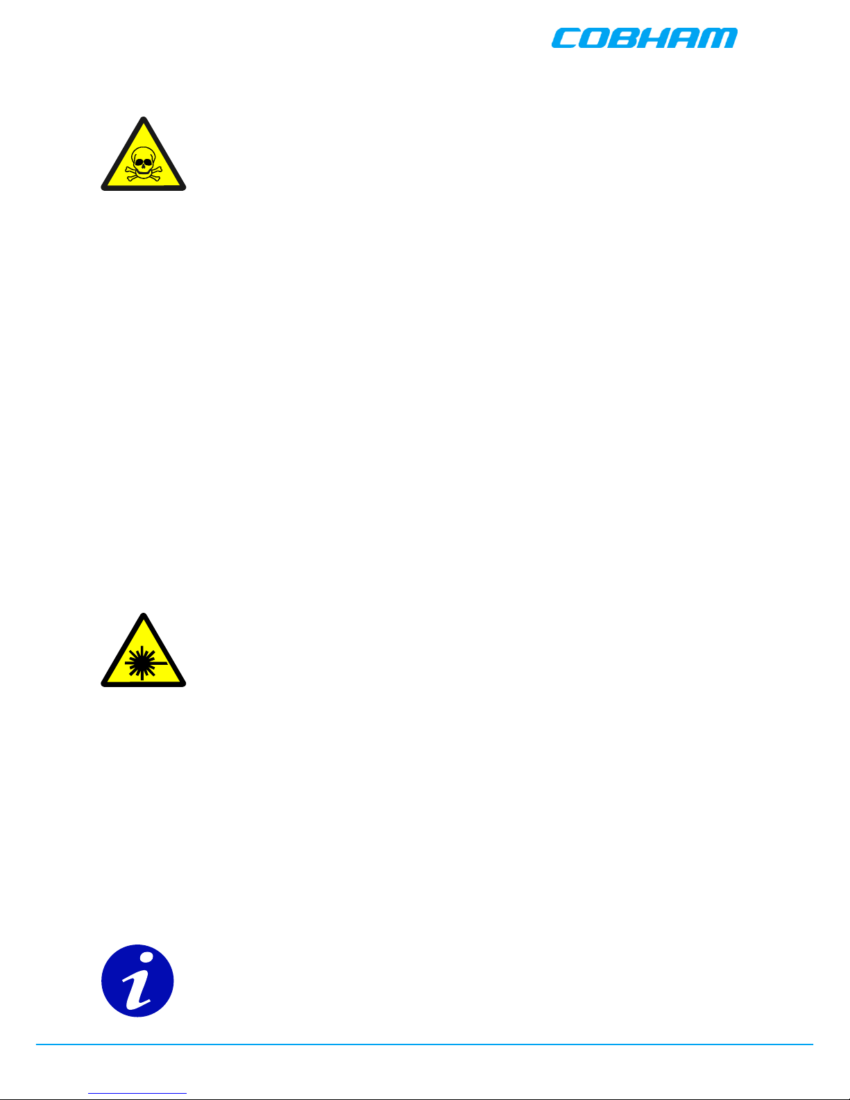
3.1. Automatic Level Control
BSF0060 is equipped with Automatic Level Control (ALC). The ALC feature enables maintaining the
maximum defined output level.
The repeater has a defined maximum output level. If the input signal amplified by the gain set
exceeds the set output limit, an ALC loop is activated. This ALC ensures that the amplifier does not
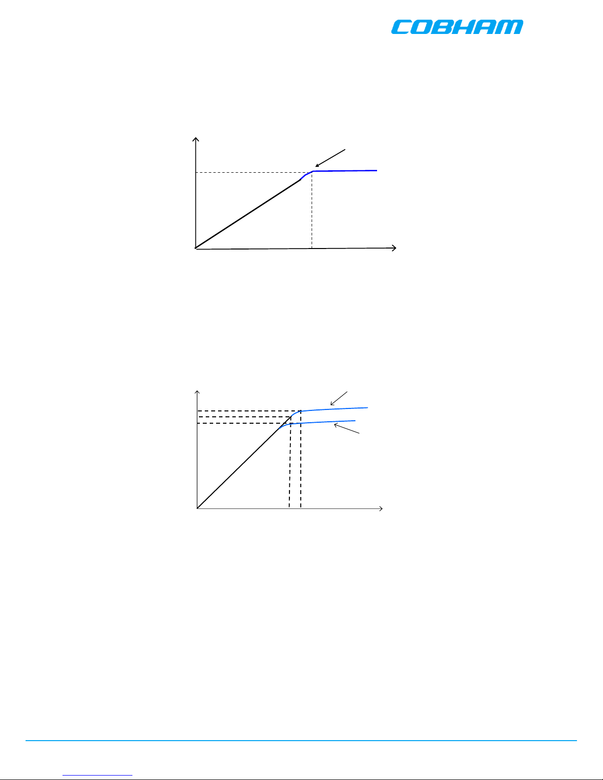
add distortion to the radio signal. Below are examples of the ALC function for one and two carriers.
+20
Input Signal, dBm
Output Power Level, dBm
Gain 70dB
-50
ALC
ALC one carrier
Input signal, dBm
Output power, dBm
+36,5
+33,8
-24 -16
Gain: 60 dB
+35
ALC two carriers

Cobham Wireless - Coverage
BSF0060 User Handbook
www.cobham.com/wireless
Document number: BSF0060HBK
Issue number: 5
Date: 14/05/2018
Page 14 of 43
3.2. BSF0060 Major Sub Components
Component
Part
Part Description
Qty. Per
Assembly
J1311001
Fibre Optic Transceiver Module
2
CM00002700
Digital Signal Processing (DSP) Module
1
B361146
Multi Carrier Power Amplifier (MCPA)
2
1513001381
Duplexer Module
1
J691001
External Interface Board
1
J755013
External Interface Cable and Terminal Block
1
J791001
PSU module 115V
2
J641030
Distribution Board
1
H481003
Control Module
1
93-000076
30dB, 1W In-Line Attenuator
1
R031002
Reference Generator
1
3.3. BSF0060 Specification
Parameter
Specification
Downlink RF Measurements
Nominal Downlink Bandwidth
5.5 MHz
Centre Frequency
408.5MHz
System net gain at 10 dB optical loss
30 dB with OMU
Gain Adjustment
0 – 30 dB in 1 dB steps
Maximum Output power
+36 dBm
Output 3rd Order Intercept Point
> +68 dBm
In-Band Spurious Noise
< -13 dBm (30 kHz B/W)
Uplink RF Measurements
Nominal Uplink Bandwidth
5.5 MHz
Centre Frequency
417.5 MHz
System net gain at 10 dB optical loss
30 dB with OMU
Gain Adjustment
0 – 30 dB in 1 dB steps
Maximum Output power
+0 dBm
In-Band Spurious Noise
< -13 dBm (30 kHz B/W)
Noise Figure
< 6 dB
General
Case Size (ex. mounting brackets)
538 mm x 382 mm x 198 mm
Case Material
Aluminium Alloy
Case Finish
Light Grey RAL7035
Supply Voltage
115 VAC 60Hz
Optical connector
SC/APC
RF Connector
7/16 DIN female
Impedance
50 Ω
Temperature
Range
operation
-25 to +55ºC
storage
-30 to +70ºC
Humidity
95% RHNC

Cobham Wireless - Coverage
BSF0060 User Handbook
www.cobham.com/wireless
Document number: BSF0060HBK
Issue number: 5
Date: 14/05/2018
Page 15 of 43
3.4. BSF0060 System Diagram

Cobham Wireless - Coverage
BSF0060 User Handbook
www.cobham.com/wireless
Document number: BSF0060HBK
Issue number: 5
Date: 14/05/2018
Page 16 of 43
3.5. BSF0060 External and Internal Views
3.5.1. External view
A
Position of external interfaces (see 3.5.2. below)
B
Door lock
C
Repeater lid securing screws

Cobham Wireless - Coverage
BSF0060 User Handbook
www.cobham.com/wireless
Document number: BSF0060HBK
Issue number: 5
Date: 14/05/2018
Page 17 of 43
3.5.2. External Interfaces
A
Cable gland for fibre optic cable connections, F/O Downlink I/P and Uplink O/P
B
7/16DIN “Server” port, RF Downlink O/P and Uplink I/P
C
Cable gland for power supply cable
D
Cable gland for wired alarm output
E
Grounding connection
F
Position of door lock

Cobham Wireless - Coverage
BSF0060 User Handbook
www.cobham.com/wireless
Document number: BSF0060HBK
Issue number: 5
Date: 14/05/2018
Page 18 of 43
3.5.3. Internal Features
A
Cable gland for fibre optic cable connections, F/O Downlink I/P and Uplink O/P
B
Fibre Optic Transceiver Module (see 3.6.2. below)
C
SC/APC F/O port
D
30dB Coaxial Attenuator
E
Digital Signal Processing Module (see 3.6.5. below)
F
Multi Carrier Power Amplifier (MCPA)
G
Duplexer Module (see 3.6.7. below)
H
7/16DIN port, RF Downlink O/P and Uplink I/P
I
Control Module (see 3.6.1. below)
J
Distribution Board (see 3.6.9. below)
K
Reference Generator Board (see 3.6.8. below)
L
External Interface Board (see 3.6.4. below)
M
Terminal block for 115V AC power connection
N
PSU module 115V (see 3.6.3. below)
O
External Interface cable and terminal block (see 3.6.4. below)

Cobham Wireless - Coverage
BSF0060 User Handbook
www.cobham.com/wireless
Document number: BSF0060HBK
Issue number: 5
Date: 14/05/2018
Page 19 of 43
3.6. Internal Modules
3.6.1. Control Module
The Control Module is based upon a Linux processor and software, which is used to control
and monitor the active components within the repeater. A Web browser accessed GUI allows
the operator to enter the required channel frequencies and to adjust the Gain and Squelch
settings.
The Control Module performs the following functions:
● Provides an RS232 and USB port for local connection enabling local interrogation of alarm
data by PC/laptop.
● Provides an Ethernet port for remote reporting/interrogation of alarm data by PC/laptop.
The controller also provides a summary alarm output upon the failure of
any active device and has four LEDs which give information regarding the
status of the Control Module.
Blue LED - Login
Quick flash
Control Module switched on, someone logged in locally and/or
remotely
Off (except for a quick
flash every 10th second)
Control Module switched on, no one logged in
Off (permanent)
Control Module switched OFF
Red LED - Status
Quick flash
Control Module switched on, one or more errors/alarms detected
Off (except for a quick
flash every 10th second)
Control Module switched on, status OK
Off (permanent)
Control Module switched off
As the BSF0060 repeater is not configured for Modem communication the two LEDs “Modem Power”
and “Modem Status” do not fill any function and can be disregarded.
MDM STATUS
MDM PWR
STATUS
LOGIN

Cobham Wireless - Coverage
BSF0060 User Handbook
www.cobham.com/wireless
Document number: BSF0060HBK
Issue number: 5
Date: 14/05/2018
Page 20 of 43
3.6.2. Fibre Optic Transceiver Module
The Fibre Optic Transceiver Module provides Optical to RF signal conversion in the Downlink direction
and RF to Optical signal conversion in the Uplink direction. As downlink and uplink optical signals are
combined using WDM, only one fibre link is required. The Fibre Optic Transceiver Module in the
repeater works in parallel with a corresponding unit in an OMU at the master site which is linked via
the optical fibre connection (SC/APC port). A pilot tone can be sent between the Fibre Optic
Transceiver Module in the OMU and the repeater to define the loss in the fibre. Based on this
information the repeater automatically adjusts the attenuation to compensate for the fibre loss.
Caution! Class 1 Laser Product.
Un-terminated optical receptacles may emit laser radiation.
Do not stare into the beam or view with optical instruments.
On the Fibre Optic Transceiver Module there are six LED indicators; one for power status, one for
error, two for the data communication and two for the Optical signals.
LED 1, Power, Green
On
Unit is powered on
Off
Unit has no power
LED 2, Error, Red
On
Error detected
Off
No error
LED 3, UL Data, Yellow
On
Communication via the fibre optic module is ongoing in the uplink direction
Off
No communication
LED 4, DL Data, Yellow
On
Communication via the fibre optic module is ongoing in the downlink
direction
Off
No communication
LED 5, Optical RX, Green
On
Input fibre optic level OK
Off
Input fibre optic level below threshold
LED 6, Optical TX, Green
On
Output fibre optic level OK
Off
Output fibre optic level below threshold

Cobham Wireless - Coverage
BSF0060 User Handbook
www.cobham.com/wireless
Document number: BSF0060HBK
Issue number: 5
Date: 14/05/2018
Page 21 of 43
3.6.3. PSU Module
The Repeater’s internal PSU Module is a high efficiency 300w switched mode device that converts the
110V AC input to a range of DC voltages (28V, 15V and 6.45V) to power the internal active modules.
The PSU Module has a switch which allows it to be set in the “on” or “standby” position; setting the
switch to standby will disable the repeater.
Note! In the standby position the PSU module and repeater are still connected to the AC power
supply but the PSU module is not operational. The PSU module on/standby switch is located on the
top of the PSU module.
The PSU Module is fitted with a rechargeable battery pack which will provide the Control Module with
enough capacity to send an alarm in the event of AC power failure. The PSU Module also includes
charging and supervision electronics for the battery backup function. The battery can be switched on
and off. The switch is placed adjacent to the PSU On/Standby switch on the top of the PSU module.
At delivery the back-up battery is connected; the battery is replaced by lifting the battery pack out of
its recess in the PSU module and disconnecting the cable.
The PSU module has four LED Status Indicators, A green LED indicates that
the input power to the PSU is functioning correctly.
Three red LEDs indicate the health of the three output voltages supplied by
the PSU.
LED 1, Input Power, Green
Slow flash
Power supply unit operating normally
OFF
Power supply unit not operating
LED 2, +6V, Red
Slow flash (every 10 seconds)
+6V power supply operating normally
Quick flash
+6V power supply not operating or operating with malfunction
LED 3, +15V, Red
Slow flash (every 10 seconds)
+15V power supply operating normally
Quick flash
+15V power supply not operating or operating with malfunction
LED 4, +28V, Red
Slow flash (every 10 seconds)
+28V power supply operating normally
Quick flash
+28V power supply not operating or operating with malfunction

Cobham Wireless - Coverage
BSF0060 User Handbook
www.cobham.com/wireless
Document number: BSF0060HBK
Issue number: 5
Date: 14/05/2018
Page 22 of 43
3.6.4. External Interface Board, Cable and Terminal Block
The repeater is equipped with an external alarm interface board. The connector terminal block for the
external alarms is located at the bottom of the repeater.
Connect the alarm cords to the terminal block according to the layout below (terminals 14 – 18 are
not used).
1
External alarm 1A
10
Alarm 0V
2
External alarm 1B
11
Relay Output 1A
3
External alarm 2A
12
Relay Output 1B
4
External alarm 2B
13
GND
5
External alarm 3A
14
Not used
6
External alarm 3B
15
Not used
7
External alarm 4A
16
Not used
8
External alarm 4B
17
Not used
9
Alarm +15V
18
Not used
External Alarm:
Four external alarm sources can be connected to the repeater; the alarm operating voltage must be
between 12 and 24VDC.
Alarm polarity can be configured:
● Active-low - when there is no voltage the alarm indicator will show a fault.
● Active-high - an applied voltage of between 12 and 24 V will cause the external alarm
indicator will show a fault.
The repeater can supply +15 VDC to an external alarm source through terminals 9 and 10. The
maximum allowed load is 100mA.
Relay Output:
The Relay Output (terminals 11 and 12) can be connected to an external device to indicate an alarm.
The output can be configured to trigger on any number of internal and external alarms. The
maximum current that can be supplied is 100mA.

Cobham Wireless - Coverage
BSF0060 User Handbook
www.cobham.com/wireless
Document number: BSF0060HBK
Issue number: 5
Date: 14/05/2018
Page 23 of 43
3.6.5. Digital Signal Processing (DSP) module
The DSP module is a wideband RF module that digitises factory set segments of the full bandwidth,
the setting of the segments of spectrum is performed at factory initialisation and is not field
adjustable. Once the equipment leaves the factory its operating bandwidth is already set by the
initialisation and the external duplexing filters used to separate and define the required Part 90 Tx
and Rx frequency bands.
The DSP module provides the initial gain in the DL path and the entire gain in the UL direction.
Internal ceramic filters provide UL and DL selectivity, in addition it provides attenuation control and
level control in both the UL and DL directions, the overall repeater has a defined maximum output
level, if the input signal amplified by the gain set exceeds the set output limit, an ALC loop is
activated in the DSP module which has a range of 20dB. This ALC ensures that the amplifier does not
add distortion to the radio signal.
3.6.6. Multi Carrier Power Amplifier (MCPA)
The Downlink output MCPA provides 37dB of gain and has a P1dB of 47dBm and an IP3 of 68dBm.
The MCPA utilises high linearity class A techniques to minimise Intermodulation generation in the
presence of multiple carriers. The amplifier output power is limited to 36dBm (4W) composite power
to ensure high linearity to keep spurious products to a minimum.
3.6.7. Bandpass Duplexer Module
The bandpass duplexer module is connected to a common output/input port for single antenna
operation. The purpose of the duplexer is to ensure that the equipment operating bandwidth is
limited to the band of frequencies required to be amplified/repeated. The filters in the duplexer
ensure that noise and any Intermodulation is limited to within the operating transmission band. The
filters must prevent any noise reaching the antenna port at the receiver frequencies as any noise at
this point will affect the ability to receive. The receiver input filter is used to ensure that only the
required input band of frequencies is presented to the DSP module. The filter also ensures that the
high level Downlink transmit output does not cause overload damage by blocking the receiver’s ability
to detect the wanted Uplink input frequencies.
3.6.8. Reference Generator Board
The Reference Generator is used to provide an accurate stable 10 MHz Reference signal to the DSP
module to ensure that the channel selectivity is centred on the wanted channel frequency.
3.6.9. Distribution Board
The Distribution board is used to connect the DC power and the RS485 control signals between the
associated modules and the PSU/Control Module.

Cobham Wireless - Coverage
BSF0060 User Handbook
www.cobham.com/wireless
Document number: BSF0060HBK
Issue number: 5
Date: 14/05/2018
Page 24 of 43
4. Antenna and Repeater Installation Requirements
This chapter provides information on the Remote installation site requirements, on the installation
requirements of the antennas, the specifications of the service antennas suitable for operation with
this remote and RF and F/O cable requirements.
4.1. BSF0060 Installation Requirements
4.1.1. Safety Guidelines
Before installing the Repeater, review the following safety information:
● Follow all local safety regulations when installing the Repeater.
● Only qualified personnel are authorized to install and maintain the Repeater.
● Ground the Repeater with the grounding bolt located on the external lower side of the
Repeater.
● Do not use the grounding bolt to connect external devices.
● Follow Electro-Static Discharge (ESD) precautions.
● Use low loss cables to connect the antennas to the Repeater.
Class 1 Laser
This product is equipped with class 1 lasers,
as per definition in EN 60825-1.
Un-terminated optical receptacles may emit laser radiation. Do not stare into the beam
or view with optical instruments
4.1.2. Criteria for Repeater Installation Location
The following criteria should be considered when selecting the Repeater installation site location:
● Application type
● General surroundings
● Available installation
● Install the Repeater in a shielded, ventilated, and easy-to-reach area.
● Verify that there is a minimum of a 50 cm (20”) radius of space around the Repeater,
enabling easy access to the repeater for maintenance and on-site inspection.
● Distance from antenna site - It is recommended that the installation location be as close as
possible to the antenna site in order to maintain the cable loss to a minimum.
● The Repeater is convection cooled so airflow and alternation should be possible.
● Follow Electro-Static Discharge (ESD) precautions.
● Install the Repeater close to the service area to monitor the output power.
● Use low loss cables to connect the antennas to the Repeater.

Cobham Wireless - Coverage
BSF0060 User Handbook
www.cobham.com/wireless
Document number: BSF0060HBK
Issue number: 5
Date: 14/05/2018
Page 25 of 43
4.1.3. RF Cable Installation Guidelines
Required:
● For all coaxial connections to/from the Repeater - high performance, flexible, low loss 50Ω
coaxial communications cable.
● All cables shall be weather-resistant type.
● Cable length - determined by the Repeater installation plan. When calculating the cable
length, take into account excess cable slack so as not to limit the insertion paths.
4.1.4. F/O Cable Installation Guidelines
Use the following over the complete link between the Remote and OMU:
● Use SC/APC connectors (8 degree angle) for all connections
● Cable length - determined by the Remote installation plan. When calculating the cable
length, take into account excess cable slack so as not to limit the insertion paths.
Recommended fiber-optic cable:
● Single-mode type fiber 9/125
4.2. Service Antenna Requirements
a. The installer is held accountable for implementing the rules required for deployment.
b. Good engineering practice must be used to avoid interference.
c. Output power should be reduced to solve any IMD interference issues.
The Service antenna type (i.e. the antenna feeding the mobile/remote units) depends on the design of the DAS.
4.2.1. Required Antenna Information
The following antenna requirements, specifications and site considerations should be met:
● Type of installation – DAS/Radiating Cable
● Service area type and size
● Antenna type and characteristics
● Height
● Length and type of coaxial cable required for connecting the antenna to the Repeater and
the attenuation.

Cobham Wireless - Coverage
BSF0060 User Handbook
www.cobham.com/wireless
Document number: BSF0060HBK
Issue number: 5
Date: 14/05/2018
Page 26 of 43
4.2.2. Indoor Installations
4.2.2.1. Recommended Antennas
The following describes the requirements for an omnidirectional mobile used for indoor applications.
Specifications:
● One or a combination of the following antennas can be used: Ceiling Mount Patch antenna,
Wall Mount Patch antenna, Corner Reflector.
● Choose an antenna with high side lobe attenuation which enables maximum isolation from
other co-located antennas.
Equation (1) - Max SERVICE antenna gain
Max SERVICE antenna gain (dBi) = 39.1 – (37 dBm - # of antennas in dB – cable losses in dB).
For example:
No. of Antennas
Cable Losses
Max Allowed Antenna Gain
4
3
39.1 - (37-6-3) = 11.1 dBi
1
3
39.1- (37-0-3) = 5.1 dBi
10
3
39.1- (37-10-3) = 15.1 dBi
Typical Antenna Types:
● Indoor Dome 2.1 dBi - beam width 360°
● Indoor Panel 4.2 dBi - beam width 106°
● Radiating Cable Typically < -50 dBi
4.2.2.2. Recommended Splitters and Couplers
Axell Wireless can supply a comprehensive range of splitters and Couplers to aid the installation of
the DAS system. Typical specifications as below:
Splitter Part Numbers
90-851202
90-851203
90-851204
Frequency Band
300 - 500 MHz
Split
2 way
3 way
4 way
Max Insertion Loss
0.3 dB
0.5 dB
0.4 dB
Split Loss
3 dB
4.8 dB
6 dB
Coupler Part Number
90-852306
90-852310
90-852315
90-852320
Frequency Band
300 - 500 MHz
Coupling
-6 dB ±1.0 dB
-10 dB ±1.0 dB
-15 dB ±1.0 dB
-20 dB ±1.0 dB
Max Mainline Loss
1.7 dB
0.8 dB
0.4 dB
0.22 dB

Cobham Wireless - Coverage
BSF0060 User Handbook
www.cobham.com/wireless
Document number: BSF0060HBK
Issue number: 5
Date: 14/05/2018
Page 27 of 43
4.2.2.3. Installation Criteria
Determine the antenna installation configuration, according to the transmission requirements and the
installation site conditions.
Installation requirements:
● An indoor antenna should be installed at a convenient location. It should be free of metallic
obstruction.
Install the Service Antenna at the designated height and tune it roughly toward the Service coverage
area.
4.2.2.4. Service (Mobile) Antenna Installation Criteria
Determine the antenna installation configuration, according to the transmission requirements and the
installation site conditions.
Installation requirements:
● An indoor antenna should be installed at a convenient location. It should be free of metallic
obstruction.
● Install the Service Antenna at the designated height and tune it roughly toward the Service
coverage area.
● Installation of this antenna must provide a minimum separation distance of 50 cm from any
personnel within the area to comply with FCC requirements and a minimum separation
distance of 2.7 m to comply with IC requiements.
4.3. RF Cabling Requirements
● For all coaxial connections to/from the Repeater - high performance, flexible, low loss 50Ω
coaxial communications cable.
● All cables shall be weather-resistant type.
● Cable length - determined by the Repeater installation plan. When calculating the cable
length, take into account excess cable slack so as not to limit the insertion paths.
● Make sure that cable and connector are compatible. Using cables and connectors from the
same manufacturer is helpful.
● All connectors must be clean and dry
● Waterproof all outdoor connections using silicone, vulcanizable tape or other suitable
substance as moisture and dust can impair RF characteristics.
● Make sure enough room has been allocated for the bending radius of the cable. RF cables
must not be kinked, cut or damaged in any way
● Connect the RF cable to the antenna tightly but without damaging threads
● Fasten cables tight to cable ladder or aluminum sheet
● For short length of feeder cables use ½ “, for longer feeder cables use 7/8”. Chose thicker
coax cables for lower attenuation. Minimize the length of the coax cables to reduce the
attenuation
● Use jumper cable for easy installation. The RF Coaxial cable can be substituted at each end
with a jumper cable.

Cobham Wireless - Coverage
BSF0060 User Handbook
www.cobham.com/wireless
Document number: BSF0060HBK
Issue number: 5
Date: 14/05/2018
Page 28 of 43
5. Repeater Installation
5.1. Location Criteria
● Wall compatibility - check the suitability of the wall on which the BSF0060 is to be to be
fitted.
● Plan mount - check the actual fixing centres (see below) and overall dimensions of the
BSF0060 enclosure. The BSF0060 is supplied with two wall mounting brackets; when the
BSF0060 is mounted on these brackets adequate ventilation is provided between the
BSF0060 and the wall to which it is fixed.
● Plan connection cable clearances - the Optical, RF and power connections located on the
underside of the BSF0060 will need at least 300mm vertical clearance below the BSF0060 to
enable the connections to be made. The minimum bend radius for Optical and RF cables
must not be less than the recommendations made by the cable manufacturer. Plan the cable
runs and ensure adequate space is available.
● Allow for door opening - ensure that there is sufficient space at the front of the BSF0060 to
allow the door to be fully opened and for maintenance engineers to get access to the unit
with test equipment such as a spectrum analyzer. Allow an additional 500mm of space in
front of the BSF0060 when the door is fully open.
● Allow for heat dispersion - Mount the repeater so that heat can be dispersed from it.
● The repeater wall mounting kit ensures an optimum airflow between the wall and the
repeater.) Do not block this air channel as it will cause the MTBF of the repeater to drop
dramatically, or even in the worst case cause the repeater to fail completely. If possible, use
a wall in the shade to minimize the overall sun loading. If sufficient shielding cannot be
obtained, an additional sun shield should be mounted.
Example of a sun shield

Cobham Wireless - Coverage
BSF0060 User Handbook
www.cobham.com/wireless
Document number: BSF0060HBK
Issue number: 5
Date: 14/05/2018
Page 29 of 43
5.2. Unpacking
Upon receiving the BSF0060 Repeater package perform the following:
● Examine the shipping container for damage before unpacking the unit.
● Perform a visual inspection to reveal any physical damage to the equipment.
● Verify that all of the equipment (listed below) is included. Otherwise contact Cobham
Wireless.
The BSF0060 Repeater package is shipped with the following equipment:
BSF0060 Repeater
CD containing User’s
Manual and USB driver
Mounting Brackets
Cable protection KPL
Additional (supplied)
installation components:
Qty.
Description
4x
M8x12 bolts for securing the Repeater to the brackets
1x
Insex tool for bolts
1x
Fiber Conduit inlet hose fitter (may be pre-assembled)
1 x
Key
Optional equipment
AC Cable [30 ft.] – Long cable for AC power
Alarm Cable [30 ft.] – Long cable for External Alarms Input

Cobham Wireless - Coverage
BSF0060 User Handbook
www.cobham.com/wireless
Document number: BSF0060HBK
Issue number: 5
Date: 14/05/2018
Page 30 of 43
5.3. Bracket Assembly
The repeater can be mounted on the wall or in a 19 inch rack.
Using the 4 provided M8 Fixing bolts and 4 spring washers assemble the brackets as illustrated below
– according to your required mounting location (wall or rack).
Wall mount bracket position
Rack-mount bracket position

Cobham Wireless - Coverage
BSF0060 User Handbook
www.cobham.com/wireless
Document number: BSF0060HBK
Issue number: 5
Date: 14/05/2018
Page 31 of 43
POWER GND OPTO
SERVER
ALARM
M8 fixing bolts
M8 fixing bolts
Fix mounting brackets to Repeater with M8
fixing bolts and spring washers supplied
Using the four M8 bolts and spring washers supplied fix mounting brackets to the Repeater
Fix mounting plates to Repeater
mounting plates fixed to Repeater

Cobham Wireless - Coverage
BSF0060 User Handbook
www.cobham.com/wireless
Document number: BSF0060HBK
Issue number: 5
Date: 14/05/2018
Page 32 of 43
368mm
378mm
Hole to take
M6 rawl bolt
Hole to take
M6 rawl bolt
189mm 189mm
Centre Line of Repeater
Hole to take
M6 rawl bolt
Hole to take
M6 rawl bolt
5.4. Mounting the Repeater onto a Wall
WARNING! Due to the weight of the Repeater, it is NOT recommended to fix the
repeater to a hollow wall
Caution: It is recommended that when lifting, two persons handle the equipment as depending upon
the configuration the Repeater weighs between 20 and 33 kg
Check the suitability of the wall on which the Repeater is to be to be fitted. At this point it is
recommended that the actual fixing centres (see below) and overall dimensions of the Repeater
enclosure are checked. The Repeater is supplied with two wall mounting brackets; when the Repeater
is mounted on these brackets adequate ventilation is provided between the Repeater and the wall to
which it is fixed.
The Optical, RF and power connections located on the underside of the Repeater will need at least
300mm vertical clearance below the Repeater to enable the connections to be made. The minimum
bend radius for Optical and RF cables must not be less than the recommendations made by the cable
manufacturer. Plan the cable runs and ensure adequate space is available.
Ensure that there is sufficient space at the front of the Repeater to allow the door to be fully opened
and for maintenance engineers to get access to the unit with test equipment such as a spectrum
analyser. Allow an additional 500mm of space in front of the Repeater when the door is fully open.
Fix M6 Rawlbolts or similar (50 to 75mm in length) into the wall at the dimensions as illustrated in
figure 1 below using equipment as specified by the fixing manufacturer. A recommended method is
set out below. Care must be taken to ensure the alignment of the four fixings. A spirit level or plumb
line should be used to ensure horizontal/vertical alignment.
Fixing centres

Cobham Wireless - Coverage
BSF0060 User Handbook
www.cobham.com/wireless
Document number: BSF0060HBK
Issue number: 5
Date: 14/05/2018
Page 33 of 43
50
-
75
mm
6
mm dia
.
Bolt head
Washer
Sleeve/Anchor
The Repeater affixed to its wall mount
brackets should be fixed to a solid wall (these
include brickwork, blockwork, and concrete.);
due to the weight of the Repeater, fixing to a
hollow wall is not recommended. Always
check that there are no pipes or cables hidden
in the wall beneath the area to be drilled.
Various pipe and cable detectors are available
to check this.
To provide secure fixing to a solid wall, the
most common method is drilling and
plugging. The size of fixing is dependent on
the item to be fixed and the nature of the wall, The Repeater should be fixed with mild steel,
M6 (x 50mm to 75mm) rawlbolts or similar.
First mark out on the chosen wall the fixing centres of the repeater (see above.).
Mark and drill the wall with the correct size masonry bit
as specified by the fixing manufacturer.
It is good practice to wear goggles to protect your eyes
from flying debris when using power tools.
Hold the drill bit against the mark and begin drilling
slowly so that the bit does not wander from the position.
The wall should be drilled to a depth which is sufficient
to accommodate the full length of the fixing.
Insert the fixings so that the top of the sleeve/anchor
section is level with the wall surface, gently tighten the
bolt by hand so that the anchor section of the fixing
expands and grips the inside of the hole.
As the bolt pulls its way in, the sides of the anchor section are
forced outwards, gripping the surrounding surface.
When all four fixings are in place,
carefully withdraw the bolt
sections and offer up the Repeater to
the wall. Great care should be exercised here as the
repeater is very heavy.
When the Repeater held in position against the wall in the
chosen position (a suitably rated heavy duty scissor
lift table/trolley may be suitable for
this operation) carefully insert the
fixing bolts through the mounting
lugs of the Repeater and into the
sleeve/anchor sections of the fixing in the wall and
tighten the bolts.
M6 rawlbolt of the type recommended to fix
Repeater and mounting plates to a wall.

Cobham Wireless - Coverage
BSF0060 User Handbook
www.cobham.com/wireless
Document number: BSF0060HBK
Issue number: 5
Date: 14/05/2018
Page 34 of 43
6. Initial Setup
Note! These are General instructions and the illustrations may not portray the specific repeater type.
The initial setup consists of the following procedures:
● Opening an RMC Session
● Assigning the Repeater general parameters: Name and clock
● Configuring the RF
6.1. Opening an RMC Session
1. Install the RMC application supplied on the Setup CD, on the computer used to open the
session to the Repeater.
2. Connect the RS232 cable between the computer and the LMT/Ethernet port on the control
module on the front panel of the repeater shelf
3. Run the application on your computer.
4. Select Serial cable Connection Type.
5. Click Next. The following dialog appears.
6. Select the COM port corresponding to the communication port on your computer to which the
RS232 cable is connected and click Connect.

Cobham Wireless - Coverage
BSF0060 User Handbook
www.cobham.com/wireless
Document number: BSF0060HBK
Issue number: 5
Date: 14/05/2018
Page 35 of 43
7. The Login dialog appears. Note that several users at a time can be logged on to a Repeater,
for instance one locally via the RS232 interface and one remotely via modem or Ethernet.
8. Enter the default login values as follows:
Login Name
Password
avitec
AvitecPasswd
case sensitive
case sensitive
Note! Do not use the number pad when entering numbers.
9. The RMC Main window appears in Console mode.
Monitoring
sub-windows
The console mode displays a large number of repeater parameters and contains a number of console
pages. The viewed information and parameters displayed correspond to the connected repeater.

Cobham Wireless - Coverage
BSF0060 User Handbook
www.cobham.com/wireless
Document number: BSF0060HBK
Issue number: 5
Date: 14/05/2018
Page 36 of 43
6.2. User Access
There is one default user name and password defined for the repeater. (More than one user at a time
can be logged in).
User Name
Password
avitec
AvitecPasswd
Note: Both the user name and the password are case sensitive.
The password can be changed and new accounts be added once a logon has been made. This is
made in terminal mode. Please refer to the document “CSR-CSFT438 Commands and Attributes”. A
user will be automatically logged out after a pre-determined period of inactivity. This time period can
be defined via the RMC.
6.3. Define Repeater General Info
When the repeater is integrated into the Active Element Manager the unit is assigned a repeater ID,
which is a unique identifier in the repeater network. This ID is used by the AEM to keep track of the
repeaters in the AEM database.
The repeater can also be assigned a nickname (TAG) which can also be easily read by the AEM during
AEM integration, providing the AEM operator a clear identification of the site.
To assign general parameters
1. In the left pane, select the Configuration window option and choose Product. The General
dialog appears.
2. In the Tag field, assign the Repeater a name (up to 30 characters) that indicates the location
of the Repeater.
The repeater tag can be locked (enable Lock TAG option) so that the tag cannot be
accidentally modified from the AEM side.
3. Set the Repeater Current Date and Current Time. These will be to timestamp events.
Note! Do not assign an ID.
The AEM will do this automatically when the repeater is integrated in the AEM.
TAG
Repeater ID assigned by AEM

Cobham Wireless - Coverage
BSF0060 User Handbook
www.cobham.com/wireless
Document number: BSF0060HBK
Issue number: 5
Date: 14/05/2018
Page 37 of 43
6.4. Configuring RF Parameters
The local setup procedure consists of verifying online communication with the connected unit,
defining the repeater channels and configuring attenuation levels and DL and UL chains.
To configure RF parameters
1. In the left pane, select the RF/Status window option. The RF Settings, Status and Levels pane
appears.
Chain
2. Define the channels to be used:
● Select an active Chain (appears in blue).
● Open the Channel list and select a channel and click OK.

Cobham Wireless - Coverage
BSF0060 User Handbook
www.cobham.com/wireless
Document number: BSF0060HBK
Issue number: 5
Date: 14/05/2018
Page 38 of 43
3. Set the D/L and U/L output power levels in the corresponding fields:
● The maximum power level can be set individually for uplink and downlink of each channel.
● The level can be set in 1 dBm steps from maximum power “Max” to maximum power minus
9 dBm “Max-9”.
● The Max. power level depends on the number of chains used (decreases with each
additional chain).
● The power level can also be set to OFF, meaning that no output power is transmitted out in
the chain.
Output power level
Note! Verify that the power levels for the inactive chains are set to OFF.
The current value can be read in the top part of this screen (36 dBm in example below).
Current measured power level
(depends on no. of chains used)
4. In Config field, select Low Delay or High Selectivity for the U/L and D/L frequencies.
5. In the Downlink:
Verify that the Return Loss is approximately 10dB, indicating the antenna is installed
correctly. (The Return Loss measures the reflected signal on the Server Antenna port of the
repeater. If the value is approximately 3dB, either the port is open or check the antenna
installation.).
Set attenuation to maximum value.
Note! The values shown in the figure below are for example only.
Config field
U/L Attenuation D/L Attenuation
Lower the Attenuation level step by step until the desired output power level is reached. In
this example +30 dBm. (Zero attenuation = maximum gain).

Cobham Wireless - Coverage
BSF0060 User Handbook
www.cobham.com/wireless
Document number: BSF0060HBK
Issue number: 5
Date: 14/05/2018
Page 39 of 43
6. In the Uplink, set the Attenuation 2dB higher than in the downlink path.
Since the base station is more sensitive than a mobile unit there may be less signal gain from
the mobile unit in to the base station (U/L) than in the opposite direction. The uplink
attenuation can be adjusted more accurately later on, once the drive test signal
measurements have been completed.
6.5. Configuring External Alarms and Relay
This section describes how to define set the external alarms to “active high” or “active low.” You can
also set the delay time (in seconds) in which a fault can be detected before an alarm is generated.
6.5.1. Configuring External Alarms
To configure the external alarms
1. In the RMC Main window, select the Configuration window option and click on Alarms.
The External Alarms configuration options are located at the bottom of the screen.
External
alarms
1. In the External Alarms Configuration area, set the levels of each alarm:
Active High – voltage triggers alarm
Active Low – no voltage triggers alarm
2. Assign a description to each relevant alarm:
In the External Alarms Description area, click Edit.
Assign a description to each relevant alarm
(up to 19 characters).

Cobham Wireless - Coverage
BSF0060 User Handbook
www.cobham.com/wireless
Document number: BSF0060HBK
Issue number: 5
Date: 14/05/2018
Page 40 of 43
6.5.2. Configuring and Testing the Relay
This section describes how to set the relay activation and how to test the Relay function.
Note! The relay status is not affected by the login / logout alarm parameters.
For installation testing purposes, it is possible to test the open / close function of the relay. This test
procedure makes sure the relay is closed for 3 seconds, then opens for 10 seconds, and finally closes
for 3 seconds before going back to original state.
1. In the RMC Main window, select the Configuration window option. The Relay configuration
options are located at the bottom of the screen.
2. The relay can be set to close or open to indicate an alarm. This can be changed by changing
the polarity.
Click to test
Set trigger for relay
6.6. TCP/IP Communication Configuration – for Remote Monitoring
A TCP/IP communication is run over a company’s network. Therefore each company needs to define
the details regarding the configuration, IP addresses, etc.
Note! For more information please refer to the document “Common Commands and Attributes”,
(available from Cobham Wireless) section 12, Network and USB Configurations.
1. Select Configuration and choose Communication. The following window appears.

Cobham Wireless - Coverage
BSF0060 User Handbook
www.cobham.com/wireless
Document number: BSF0060HBK
Issue number: 5
Date: 14/05/2018
Page 41 of 43
2 Set the IP Address
method as either
Dynamic or Static.
3. Set the DNS or Gateway
address.
6.7. Integration into the AEM
When the repeater has been installed at site and the remote communication has been enabled, the
repeater can be integrated to the Active Element Manager. This is done by the operator of the AEM.
After entering the telephone number to the repeater, the AEM dials up the repeater, downloads all
the repeater parameters and statuses into a database. When all parameters have been downloaded,
the AEM configures the repeater with the telephone number where alarms and reports should be
sent, and optionally with a secondary telephone number where the repeater can dial in case
connection to primary number fails.
When heartbeat reports and alarms are sent from the repeater to the AEM also the latest information
about the status and RF-configuration is included. This means that the AEM operator always has
information about the current status in the AEM database (and do not need to call the repeater to
find this out).
Note! Once the repeater is integrated to the AEM, all changes to the repeater should preferably be
done from the Active Element Manager in order to ensure that the database always contains
correct information.

Cobham Wireless - Coverage
BSF0060 User Handbook
www.cobham.com/wireless
Document number: BSF0060HBK
Issue number: 5
Date: 14/05/2018
Page 42 of 43
Appendix
A.1. Glossary of Terms used in this document
Repeater or
Cell Enhancer
A Radio Frequency (RF) amplifier which can simultaneously amplify and re-broadcast Mobile
Station (MS) and Base Transceiver Station (BTS) signals.
Band Selective
Repeater
A Repeater designed for operation on a range of channels within a specified frequency
band.
Channel Selective
Repeater
A Repeater, designed for operation on specified channel(s) within a specified frequency
band. Channel frequencies may be factory set or on-site programmable.
AC
Alternating Current
AEM
Active Element Manager (Network control and monitoring software)
AGC
Automatic Gain Control
BBU
Battery Backup Unit
BDA
Bi-directional Amplifier
BTS
Base Transceiver Station (Base Station)
B/W
Bandwidth
C/NR
Carrier-to-Noise Ratio
COMMUX
Communications Multiplexer
Critical Harness
A coaxial cable harness with components of a critical length used to minimise phase
discrepancies when joining signal paths of differing frequencies.
DAS
Distributed Antenna System
DC
Direct Current
Downlink (D/L)
Signals transmitted from the BTS to the Mobiles
DSP
Digital Signal Processing
F/O
Fibre Optic
GND
Ground
ID
Identification (Number)
I/P
Input
LCX
Leaky Coaxial Cable (Leaky Feeder).
LED
Light Emitting Diode
LNA
Low Noise Amplifier
LPA
Low Power Amplifier
Mobile(s)
Hand-portable or other “Mobile” RF Transceiver equipment
MOU
Master Optical Unit
MTBF
Mean Time Between Failures
N/A
Not Applicable
N/C (of Relays)
Normally Closed
N/O (of Relays)
Normally Open
OFR
On Frequency Repeater
OIP3
Output Third Order Intercept Point
O/P
Output
P1dB
1dB Compression Point
PA
Power Amplifier
RF
Radio Frequency
RHNC
Relative Humidity, Non Condensing
RMC
Repeater Maintenance Console (a GUI based Repeater management application)
RSA
Receiver/Splitter Amplifier
RX
Receiver (Received)
SDR
Software-Defined Radio
S/N
Serial Number
TX
Transmitter (Transmitted)
Uplink (U/L)
Signals transmitted from the Mobiles to the BTS
UPS
Uninterruptible Power Supply
VSWR
Voltage Standing Wave Ratio
WDM
Wave division multiplex
Date Format
Date Format used in this document is dd/mm/yyyy

Cobham Wireless - Coverage
BSF0060 User Handbook
www.cobham.com/wireless
Document number: BSF0060HBK
Issue number: 5
Date: 14/05/2018
Page 43 of 43
A.2. Document Amendment Record
Issue
No.
Date
Incorporated
by
Section
Amended
Reason for new issue
1
24/11/2015
AJS Draft
2
22/01/2016
AJS Issue
3
19/09/2016
AJS Bandwidth revision
4
12/12/2016
AJS Gain figures revision
5
14/05/2018
AJS ISED compliance statement.
 Loading...