

Page 1
SAILOR 619 4
Terminal Control Unit
Installation and user manual
Page 2

Page 3

SAILOR 6194 Terminal Control Unit
Installation and user manual
Document number: 98-131593-D
Release date: November 18, 2013
i
Page 4

Disclaimer
Any responsibility or liability for loss or damage in connection with the use of this
product and the accompanying documentation is disclaimed by Thrane & Thrane
A/S. The information in this manual is provided for information purposes only, is
subject to change without notice and may contain errors or inaccuracies. Manuals
issued by Thrane & Thrane A/S are periodically revised and updated. Anyone relying
on this information should acquire the most current version e.g. from
www.cobham.com/satcom or from the distributor. Thrane & Thrane A/S is not
responsible for the content or accuracy of any translations or reproductions, in whole
or in part, of this manual from any other source.
Thrane & Thrane A/S is trading as Cobham SATCOM.
Copyright
© 2013 Thrane & Thrane A/S. All rights reserved.
Trademark acknowledgements
• Inmarsat is a registered trademark of the International Maritime Satellite
Organisation (IMSO) and is licensed by IMSO to Inmarsat Limited and Inmarsat
Ventures plc.
• SAILOR is a registered trademark of Thrane & Thrane A/S in the European Union,
the United States and other countries.
• Other product and company names mentioned in this manual may be trademarks
or trade names of their respective owners.
ii
Page 5

Safety summary
The following general safety precautions must be observed during all
phases of operation, service and repair of this equipment. Failure to
comply with these precautions or with specific warnings elsewhere in this
manual violates safety standards of design, manufacture and intended
use of the equipment. Thrane & Thrane A/S assumes no liability for the
customer's failure to comply with these requirements.
GROUND THE EQUIPMENT
To minimise shock hazard, the equipment chassis and cabinet must be
connected to an electrical ground and the cable instructions must be
followed.
DO NOT OPERATE IN AN EXPLOSIVE ATMOSPHERE
Do not operate the equipment in the presence of flammable gases or
fumes. Operation of any electrical equipment in such an environment
constitutes a definite safety hazard.
KEEP AWAY FROM LIVE CIRCUITS
Operating personnel must not remove equipment covers. Component
replacement and internal adjustment must be made by qualified
maintenance personnel. Do not service the unit with the power cable
connected. Always disconnect and discharge circuits before touching
them.
DO NOT SUBSTITUTE PARTS OR MODIFY EQUIPMENT
Because of the danger of introducing additional hazards, do not
substitute parts or perform any unauthorised modification to the
equipment.
COMPASS SAFE DISTANCE
20 cm
iii
Page 6

About the manual
Intended readers
This manual is primarily an installation manual for the Terminal
Control Unit Terminal Control Unit. The manual is intended for
installers of the system and service personnel. Personnel
installing or servicing the system must be properly trained and
authorised by Cobham SATCOM. It is important that you
observe all safety requirements listed in the beginning of this
manual, and install the system according to the guidelines in this
manual.
The manual also describes some basic configuration of the
system, the use of SSA buttons and scripting.
See also the user manual for the system in which the Terminal
Control Unit is installed, e.g. SAILOR 6120 SSA System. Related
manuals are listed on the next page under Related documents.
iv
Page 7
Related documents
The below list shows the documents related to this manual and
to this product.
The manuals can be found in the Self Service Center at
cobham.com/satcom under Service and Support.
Ref. Title and description
[1] SAILOR 6006 and SAILOR 6007,
Message Terminal, Installation manual
[2] SAILOR 6110 GMDSS System,
Installation manual
[3] SAILOR 6110 GMDSS System, User
manual
[4] SAILOR 6120/6130/6140/6150
System, Installation manual
[5] SAILOR 6120/6130/6140/6150
System, User manual
[6] SAILOR 6081 Power Supply and
Charger, Installation and user manual
[7] System 6000 GMDSS Console,
Installation manual
Table 1: Related documents
Document
number
98-130088
98-130752
98-130753
98-131589
98-131590
98-130980
98-131571
v
Page 8

vi
Page 9

Table of Contents
Chapter 1 Introduction
The Terminal Control Unit ...............................................................1
Chapter 2 Installation
Unpacking ................................................................................................3
Installing the Terminal Control Unit ............................................4
Outline drawing .....................................................................................6
Installing Ship Security Alert (SSA) buttons ............................7
Installing Non-SOLAS Alarm Panels .............................................9
Installing the Glonass option ....................................................... 10
Chapter 3 Connecting cables
Connector overview .........................................................................14
Power control (X1) ............................................................................15
CAN interface (X2) ............................................................................16
RS-232 interface (X5) ......................................................................19
LAN interface (X6) ............................................................................. 20
SSA and Alarm Panel (X7 to X14) ..............................................21
Grounding the Terminal Control Unit ...................................... 26
Cable requirements ...........................................................................27
Chapter 4 Using the Terminal Control Unit
Status indicators ................................................................................30
Configuration ......................................................................................35
Use of SSA buttons ........................................................................... 44
vii
Page 10

Table of Contents
Use of Non-SOLAS Alarm Panels ................................................46
Chapter 5 Scripting
Introduction to scripting ................................................................47
What can scripts do .......................................................................... 48
Complete example of a Lua script ............................................. 52
Chapter 6 Service
Updating software ............................................................................ 59
Status signalling .................................................................................. 62
Setting a temporary fixed IP address ......................................63
Returning units for repair ...............................................................64
Repacking for shipment .................................................................. 64
App. A Specifications
General specifications for the TCU ........................................... 65
Specifications for I/O pins ............................................................. 66
App. B Lua extensions
GPIO functions ....................................................................................69
Miscellaneous functions .................................................................74
Glossary .....................................................................................................................81
Index .....................................................................................................................85
viii
Page 11

Chapter 1
Introduction 1
The Terminal Control Unit
The Terminal Control Unit is used for the following purposes:
• For connecting covert alert buttons for use in Ship Security Alert (SSA)
systems or SAILOR 3042E Alarm Panels in Non-SOLAS Distress systems.
• For connecting a SAILOR 3027 terminal, which has a CAN interface,
with other equipment that has Ethernet or RS-232 interface.
• For executing custom scripts that can react on events registered by the
Terminal Control Unit, e.g. in SCADA applications and for vessel
monitoring.
You can also connect a switch for power control of the Terminal Control
Unit, and with the optional Glonass module you can connect to a Glonass
antenna.
The power for the Terminal Control Unit is supplied through the CAN
connector (extended input range 10.5-32 V DC).
Introduction
The Terminal Control
Unit is supported by
the ThraneLINK
Management
Application, a
Windows program
that provides easy
monitoring and
software update of
connected Cobham
SATCOM devices with
ThraneLINK support.
1
Page 12

Chapter 1: Introduction
2 The Terminal Control Unit
Page 13
Chapter 2
Installation 2
This chapter describes how to unpack, store and install the
SAILOR 6194 Terminal Control Unit. It contains the following sections:
• Unpacking
• What’s in the delivery
• Installing the Terminal Control Unit
• Outline drawing
• Installing Ship Security Alert (SSA) buttons
• Installing Non-SOLAS Alarm Panels
• Installing the Glonass option
For information on cable connections, see Connecting cables on page 13.
Unpacking
Installation
Initial inspection
Inspect the shipping carton immediately upon receipt for evidence of
damage during transport. If the shipping carton is severely damaged or
water stained, request that the carrier's agent be present when opening the
carton. Save the carton packing material for future use.
Warning! To avoid electric shock, do not apply power to the
system if there is any sign of shipping damage to any
part of the front or rear panel or the outer cover.
Read the safety summary at the front of this manual
before installing or operating the system.
After unpacking the system, inspect it thoroughly for hidden damage and
loose components or fittings. If the contents are incomplete, if there is
mechanical damage or defect, or if the system does not work properly,
notify your dealer.
3
Page 14

Chapter 2: Installation
What’s in the delivery
The following items are included in the delivery of the Terminal Control
Unit:
• Terminal Control Unit Terminal Control Unit
• NMEA2000 Micro Device Cable, 6 m
• Mounting tool for spring-loaded terminals
• Installation and user manual (this manual)
Installing the Terminal Control Unit
General installation requirements
The Terminal Control Unit must be installed in a location which is
• indoors
• not exposed to water
• close to a ship ground connection point.
Make sure the Compass Safe Distance is maintained. See General
specifications for the TCU on page 65.
Mounting the Terminal Control Unit
The Terminal Control Unit is designed to be mounted on a flat surface, e.g.
on a bulkhead.
Important
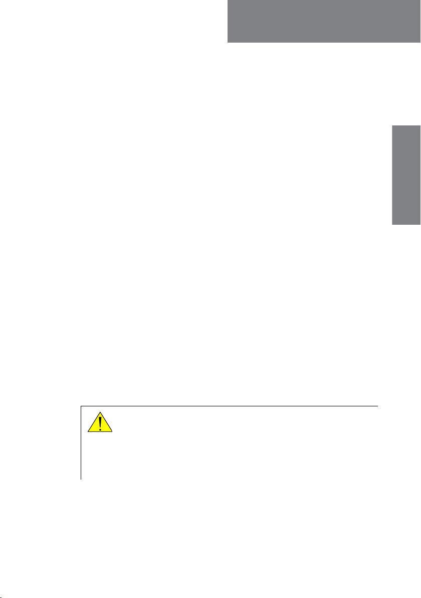
To mount the Terminal Control Unit, do as follows:
1. Using four screws, mount the Terminal Control Unit on the mounting
surface. The mounting holes are Ø6. If you mount the Terminal Control
4 Installing the Terminal Control Unit
If the Terminal Control Unit is not mounted on a surface with
a good connection to ship ground, you must connect a
separate cable for this purpose. See Grounding the Terminal
Control Unit on page 26.
Page 15
Chapter 2: Installation
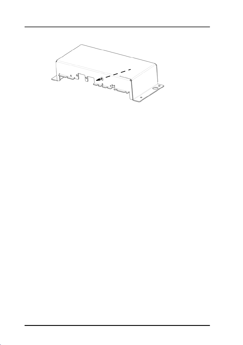
Unit on a vertical surface, make sure the cable relief is facing down as
shown in the picture below.
Cable relief
for CAN
2. Tighten the screws.
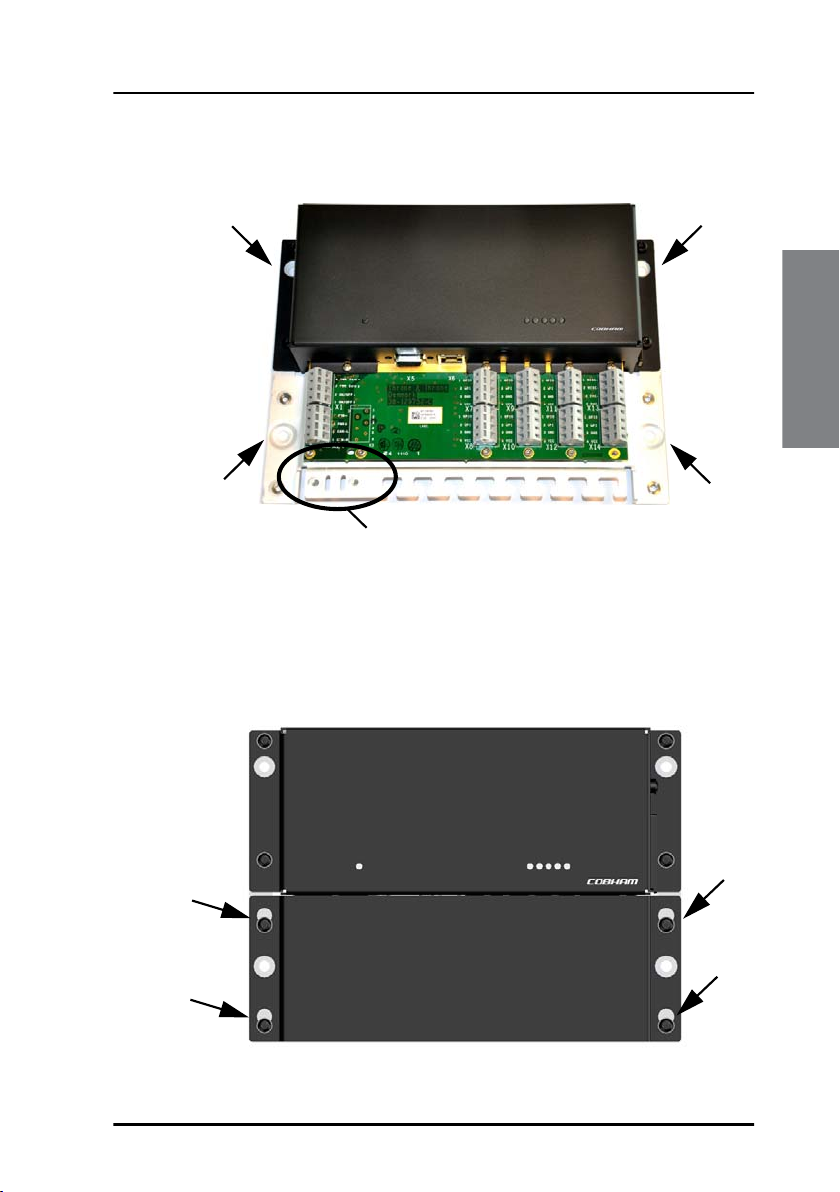
3. Connect all cables as described in Connecting cables on page 13 and
fasten the cables to the cable relief with cable strips.
Installation
4. When all cables are installed, mount the cover for the spring-loaded
terminals. Tighten the screws to 1.5 Nm.
Installing the Terminal Control Unit 5
Page 16
Chapter 2: Installation
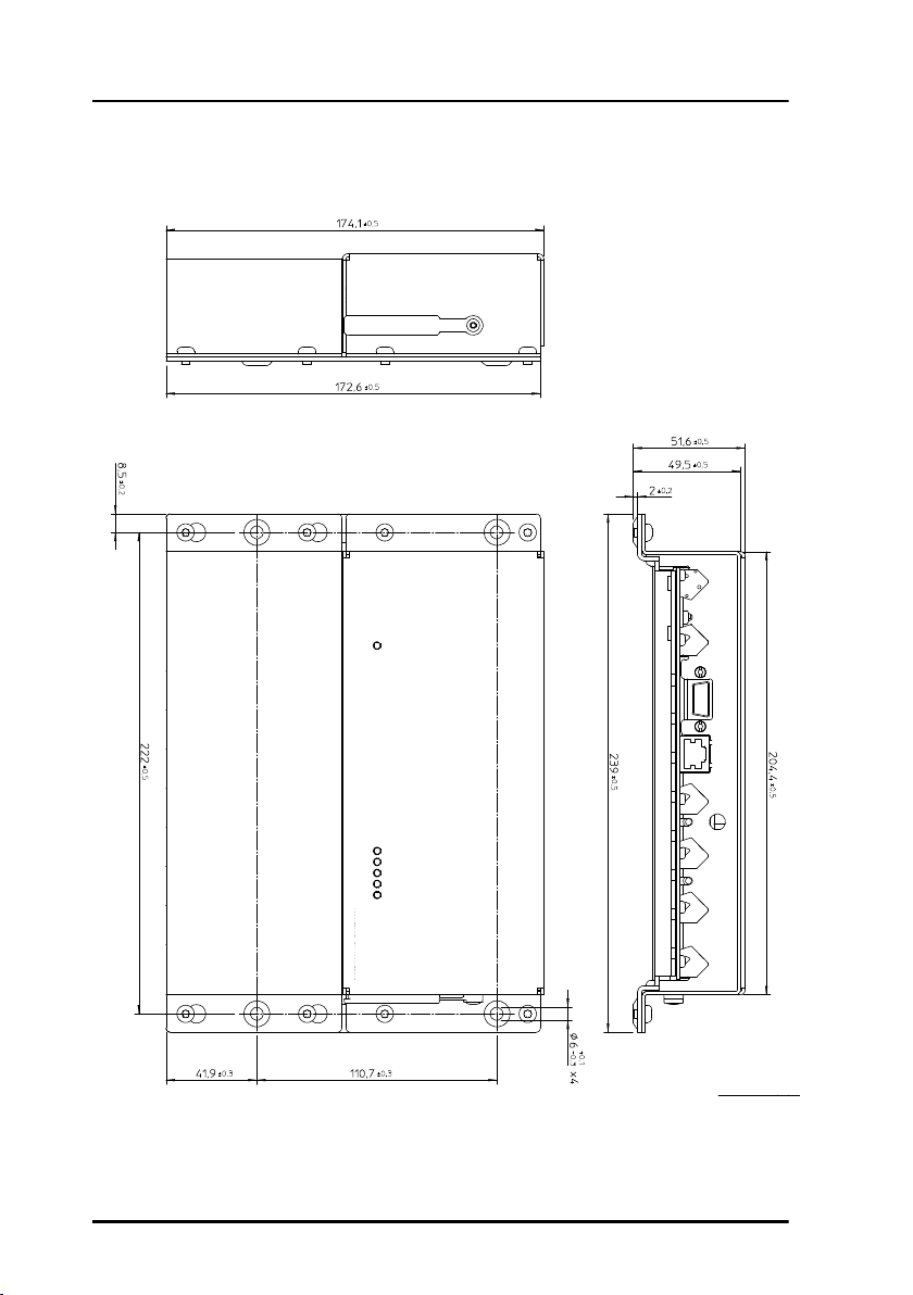
Outline drawing
Dimensions are in mm
6 Outline drawing
Page 17

Chapter 2: Installation
Installing Ship Security Alert (SSA) buttons
Placing the SSA buttons
To fulfil the IMO requirement on covert activation, the alert button
installation must be concealed using appropriate covert installation
techniques. One of the alert buttons must be placed on the ship’s
navigation bridge. To make testing easier we recommend installing the test
button close to one of the covert alert buttons, but in such a way that the
constant light does not disturb navigation (night sight). The test button
must be installed where it is easy to test the SSA installation at regular
intervals.
Installing the SSA buttons
When the place for installation is determined, do as follows:
1. Drill a hole with a diameter of 16 mm.
2. Place the mounting-nut and the large piece of heat-shrink 19x30 mm
on the back of the hole.
Installation
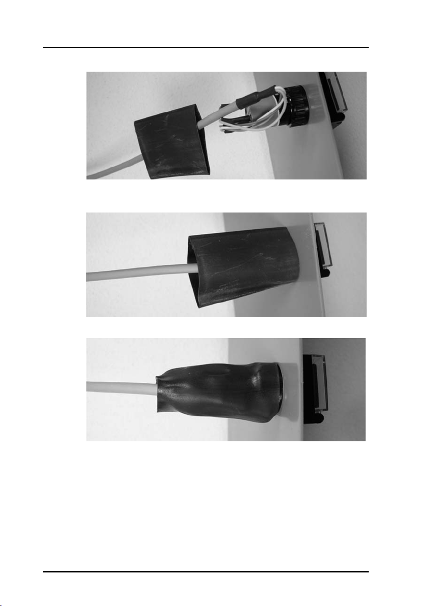
3. Slip the wires from the covert alert button through the hole, the
mounting nut, the heat-shrink, and all the way to the Terminal Control
Unit.
The 19x30 mm heat-shrink is for cable strain relief on the back of the
button.
4. Tighten the mounting nut.
5. Bend the cable in an S shape on the side of the switch.
Installing Ship Security Alert (SSA) buttons 7
Page 18
Chapter 2: Installation
6. Pull the heat-shrink to the back of the board where the button is
installed.
7. Shrink the heat-shrink with heat.
For information on wiring, see GMDSS or SSA systems (SAILOR 6110 or
SAILOR 6120) on page 21. For information on how to configure the SSA
buttons, see Configuring SSA buttons on page 39. For information on how
to use the SSA buttons, see Use of SSA buttons on page 44.
8 Installing Ship Security Alert (SSA) buttons
Page 19
Chapter 2: Installation
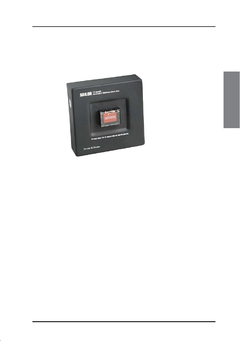
Installing Non-SOLAS Alarm Panels
The Non-SOLAS Alarm Panel is used in Non-SOLAS Distress systems to send
Distress alerts. You may use the SAILOR 3042E Alarm Panel.
The Non-SOLAS Alarm Panel can be mounted on a wall or desktop.
For information on wiring, see Non-SOLAS Distress systems (SAILOR
6150) on page 23.
Installation
Installing Non-SOLAS Alarm Panels 9
Page 20
Chapter 2: Installation
Installing the Glonass option
An optional Glonass module is available for the Terminal Control Unit. The
Glonass module enables the Terminal Control Unit to receive a Glonass
signal and make it available to other parts of the system.
Caution! Before removing the cover enclosing the electronic
circuits, first make sure you are wearing a wrist strap
connected to the work place.
To install the Glonass module, do as follows:
1. Unscrew the screws holding the cover for the electronic circuits and
remove the cover.
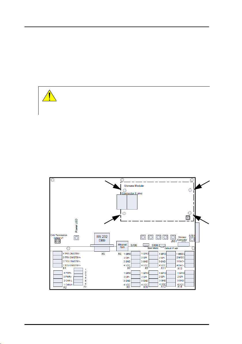
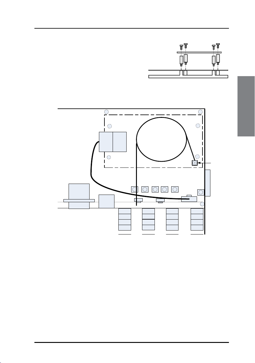
2. Mount the four threaded spacers in the positions shown below, through
the main PCB and into the threaded bushings in the bottom of the
Terminal Control Unit. Tighten them to 1 Nm.
Spacers and screws x 4
10 Installing the Glonass option
Page 21
Chapter 2: Installation
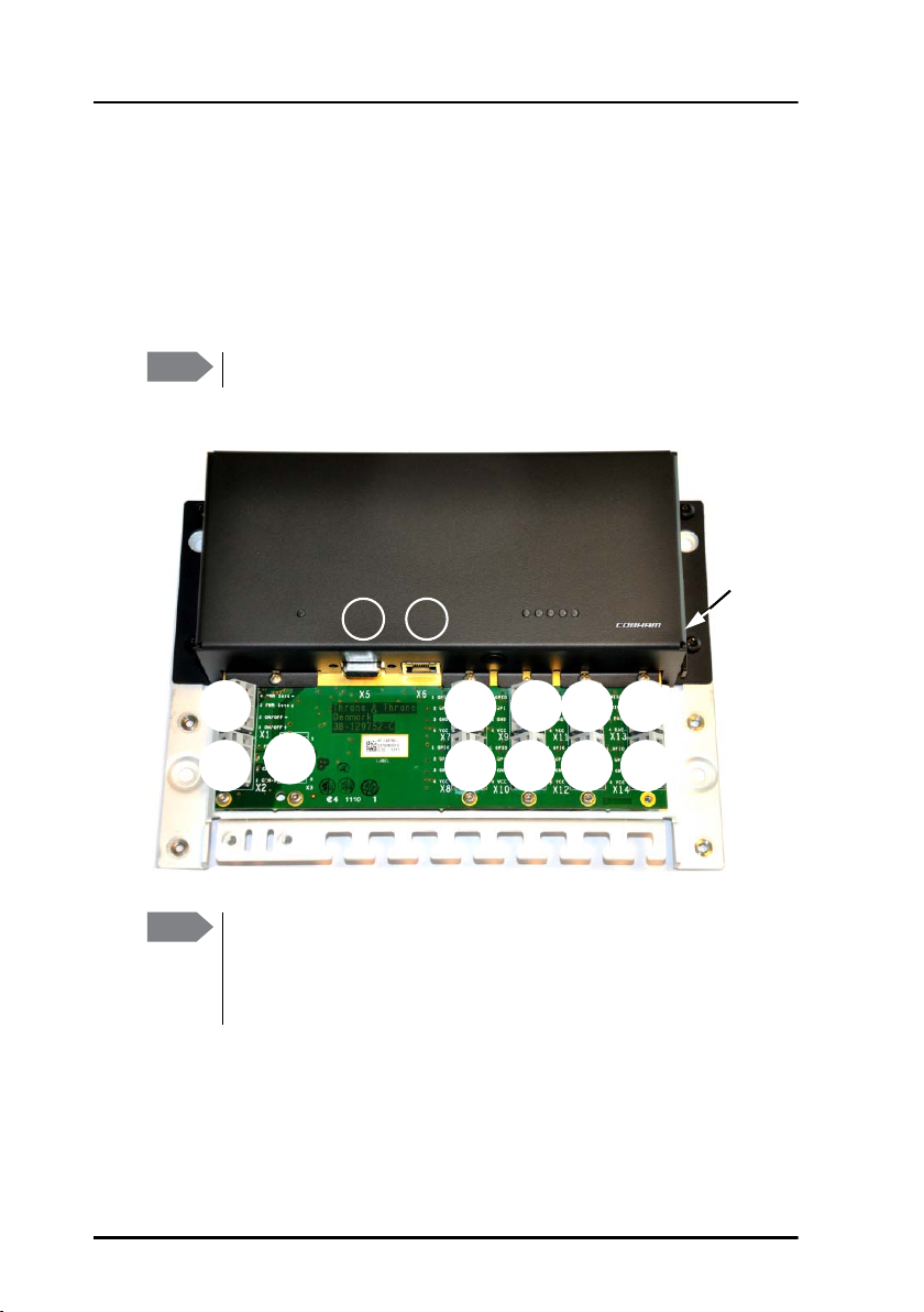
3. Place the Glonass module over the
four spacers and mount the four
screws through the holes in the
Glonass module and into the
spacers.
Tighten the screws to 1 Nm.
4. Connect the cable harness from the Glonass module to the connector
J901 in the Terminal Control Unit.
RS 232
DB9
X5
Glonass Module
Connector 8 pins
5 X STATUS LED’s
Ethernet
S700
Rj45
1 GPIO
X6
2 GPI
3 GND
4 VCC
X7
1 GPIO
2 GPI
3 GND
4 VCC
X9 X11
1 GPIO
2 GPI
3 GND
4 VCC
Coax Cable
Connector
J901
1 MISC+
2 MISC-
3 DAC+
4 DAC-
X13
Glonass
Glonass
antenna
connector
5. Lead the external connector on the antenna cable through the hole
indicated in the drawing below and fasten it to the cover with the nut
on the connector.
Installation
Installing the Glonass option 11
Page 22
Chapter 2: Installation
6. Connect the internal connector on the antenna cable to the antenna
connector on the Glonass module as shown in the drawing in step 4.
7. Mount the cover and fasten the screws to 1.5 Nm.
For information on how to configure the Glonass module see Configuring
the Glonass option on page 42.
12 Installing the Glonass option
Page 23

Chapter 3
Connecting cables 3
This chapter provides a description of the connectors on the Terminal
Control Unit and gives guidelines to cabling. It has the following sections:
• Connector overview
• Power control (X1)
• CAN interface (X2)
• RS-232 interface (X5)
• LAN interface (X6)
• SSA and Alarm Panel (X7 to X14)
• Grounding the Terminal Control Unit
• Cable requirements
Connecting cables
13
Page 24
Chapter 3: Connecting cables
Connector overview
The drawing below shows the connectors on the Terminal Control Unit and
the SD card slot for inserting an SD memory card.
X5 and X6 are standard connectors for RS-232 (9-pin D-sub) and Ethernet
(RJ-45), all other connectors are spring-loaded terminals.
Note
Note
X3 and X13 are for future use.
SD card
slot
X5 X6
X1
X2
X3
X7
X9 X11 X13
X14X12X10X8
Some of the spring terminals can change function depending on
the connected equipment or by means of software commands.
See the available functions in SSA and Alarm Panel (X7 to X14) on
page 21.
14 Connector overview
Page 25

Chapter 3: Connecting cables
Power control (X1)
By default, when the system is powered on, the Terminal Control Unit and
the connected mini-C Terminal are always on. If you want to change this
behaviour, you must configure the X1 connector using a software
command (Constant_On 0). For details see Setting up software
controlled power management on page 40.
Important
If you have configured X1 with the command
Constant_On 0, you cannot switch on the system until
you connect pin 1 and 2 in X1 with a switch.
Remote on/standby
When X1 is configured for power
management, Pin 1 and 2 in the connector X1
can be used for switching between on and
standby on the Terminal Control Unit and
the mini-C Terminal. Connect a switch
between the two pins if you want to be able
to set the Terminal Control Unit and the miniC Terminal in standby mode independently of the rest of the system.
• Open contact: The Terminal Control Unit and the mini-C Terminal are in
standby mode.
• Closed contact: The Terminal Control Unit and the mini-C Terminal are
always on.
Pin 3 and 4 are for future use.
Power management (only SAILOR 6140 and SAILOR
6150)
Connecting cables
Note
When X1 is enabled and the switch is open (standby), you can control the
power management with software. See Setting up software controlled
power management on page 40.
Note that software controlled power saving functions are not
available in GMDSS, SSA nor LRIT systems.
Power control (X1) 15
Page 26

Chapter 3: Connecting cables
CAN interface (X2)
The Terminal Control Unit has one CAN interface (spring-loaded terminals)
used for communicating with connected equipment, such as a Message
Terminal and/or a mini-C GMDSS terminal. The CAN interface is located in
the bottom left corner of the Terminal Control Unit as shown below.
Important
Do not connect the shield of the CAN cable to the chassis of
the Terminal Control Unit, or to any other ship ground
connection on the Terminal Control Unit. For safety reasons
the CAN shield must only be connected to ship ground at the
power supply.
CAN termination
jumper
CAN
interface
To connect the CAN interface, insert the wires as shown in the drawing
above. Use the tool supplied with the Terminal Control Unit to open the
spring-loaded terminals.
Power input
There are 2 different options for the power input:
• The Terminal Control Unit can be powered through the CAN bus
(extended range: 10.5-32 V DC).
Note
If your power source is supplying more than 15 V, the system
is not protected against incorrect wiring.
16 CAN interface (X2)
Page 27
Chapter 3: Connecting cables
• In systems where CAN power is not available, you can connect your
power supply or battery to pin3 PWR+ and pin 4 PWR- shown in the
drawing on page 16, if the power supply is within the limits stated in
General specifications for the TCU on page 65.
Caution! If your power source is a battery, you must
configure an under-voltage protection for the
battery. The battery may be damaged if the
correct under-voltage protection is not applied!
For details, see the next section, Under-voltage
protection.
Under-voltage protection
If the power source is a battery, you must configure the Terminal Control
Unit to the correct under-voltage protection as follows:
1. Connect a computer to the Terminal Control Unit and start a terminal
program as described in Using commands on page 35.
2. At the tt6194:/$ prompt, type in the relevant command,
depending on the source voltage:
• Disable UVP: Type avr_uvp 0
• 24 V: Type avr_uvp 1
• 12 V: Type avr_uvp 2
• CAN voltage: type avr_uvp 3
120 Ohm termination for CAN interface
Caution! Before removing the cover enclosing the electronic
circuits, first make sure you are wearing a wrist strap
connected to the work place in to avoid ESD
(ElectroStatic Discharge).
Connecting cables
CAN interface (X2) 17
Page 28

Chapter 3: Connecting cables
A double jumper, J1 in the drawing on page 16, connects a 120 Ohm
termination for the CAN interface. If you have terminated the CAN
connection elsewhere and want to remove the termination in the Terminal
Control Unit, you must remove the jumper. To access the jumper you must
first remove the cover by unscrewing the screws holding the cover.
18 CAN interface (X2)
Page 29
Chapter 3: Connecting cables
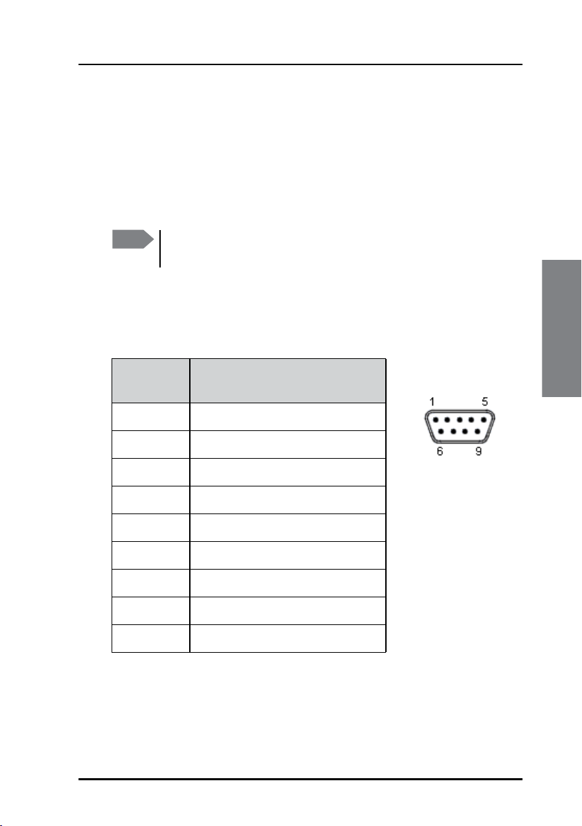
RS-232 interface (X5)
Overview
There is one RS-232 connector, 9-pin D-Sub, on the Terminal Control Unit.
The RS-232 (DTE) interface can be used for entering commands or running
scripts on the Terminal Control Unit.
Note
The default setup for the RS-232 interface is 115200 bps 8N1.
You must use this setting the first time you connect.
Pin-out
The figure and table below show the connector outline and pin
assignments.
Pin
number
1 Not Connected
2 RxD (Receive Data) Input
3 TxD (Transmit Data) output
4 Not Connected
5 GND
6 Not Connected
7 Not Connected
8 Not Connected
9 Not Connected
Pin function
D-Sub, 9 pin male
Connecting cables
Table 1:
RS-232 interface (X5) 19
Page 30
Chapter 3: Connecting cables
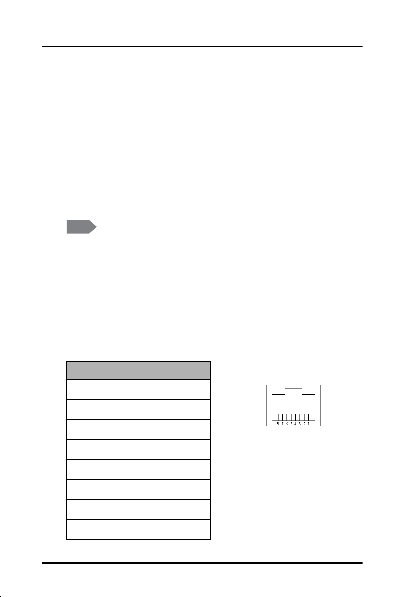
LAN interface (X6)
Overview
There is one Ethernet (10/100 MB) connector on the Terminal Control Unit.
We recommend connecting to the slave unit, in order to reserve the free
LAN connectors for user interfaces on the master unit.
The Ethernet interface can be used to connect a computer and use the
easyMail program supplied on CD with the Terminal Control Unit, the
ThraneLink Management Application or a terminal program to access the
Terminal Control Unit or the connected SAILOR 3027.
Note
To access the Terminal Control Unit through the LAN interface
you must know the IP address of the Terminal Control Unit. The
ThraneLink Management Application lists all connected units with
their IP addresses. For details, see Updating software on page 59.
You may also define a temporary IP address for the Terminal
Control Unit.
Pin-out
The figure and table below show the connector outline and pin
assignments.
Pin number Pin function
1
2
3
4
5
6
7
Rx+
Rx-
Tx+
Not connected
Not connected
Tx-
Not connected
RJ-45 female
8
20 LAN interface (X6)
Not connected
Page 31

Chapter 3: Connecting cables
SSA and Alarm Panel (X7 to X14)
Some of the spring-loaded terminals can have different functions,
depending on the system configuration.
The function of the I/O pins are automatically configured to match the
connected type of satellite terminal. Depending on the connected terminal,
some of the I/O pins are preconfigured, and some of the I/O pins are
configurable.
The general purpose inputs and outputs can be used for various
applications, e.g. temperature sensors, trawl indicators, flow meters/level
sensors or ignition ON indication.
Note
The following sections describe some of the possible configurations.
For specifications of the general purpose inputs/outputs, see
Specifications for I/O pins on page 66.
GMDSS or SSA systems (SAILOR 6110 or SAILOR
6120)
You can use the Terminal Control Unit for connecting alarm and test
buttons for use in SSA systems. When a SAILOR 3027C or SAILOR 3027SSA
terminal is connected, X7 to X14 are automatically configured as shown
below. X13 is not used.
Important
If you are not using all terminal blocks assigned for SSA alarm
buttons (X7 to X12), make sure pin 1 and 2 are shorted in the
terminal blocks that are not used. This only applies to the
alarm buttons X7 to X12, not to the test button X14.
Connecting cables
SSA and Alarm Panel (X7 to X14) 21
Page 32

Chapter 3: Connecting cables
The Terminal Control Unit can connect up to 6 alarm buttons and 1 test
button. The pin-out is shown below.
The following spring-loaded terminals are used for the buttons:
• SSA Alarm buttons: X7, X8, X9, X10, X11 and X12.
• SSA Test button: X14.
Note
Before inserting the wires into the terminals, make sure there is no
jumper between pin 1 and 2 (Output and Input).
Connect the buttons as shown below:
Brown
3
Green
4
Yellow
White
Green
Yellow
Brown
Terminal
Block
X7-X12
Terminal
Block
X14
PIN 1 Out 1
PIN 2 In
PIN 3 GND
PIN 4 3,3V
PIN 1 Out
PIN 2 In
PIN 3 GND
PIN 4 3,3V
22 SSA and Alarm Panel (X7 to X14)
NONC
SSA
Button 1-6
2
NO
a
SSA Test
1
Button
2
b
Page 33

Chapter 3: Connecting cables
Note that there may also be a white wire in the cables for the SSA Alarm
buttons. Do not connect the white wire from the red SSA alarm buttons only from the Test button.
Non-SOLAS Distress systems (SAILOR 6150)
The multi-purpose interface on the Terminal Control Unit can also connect
to Non-SOLAS Alarm Panels e.g. in Non-SOLAS Distress installations. When
a SAILOR 3027D is connected, X8, X10, X12 and X14 are automatically1
configured as shown in the two following drawings. X13 is not used.
With 1 TT-3042E Non-SOLAS Alarm Panel (Inmarsat C Distress
Alarm Box):
6$,/25
1RQ62/$6
6KLSJURXQGKXOO
6KLHOG
3RZHUVXSSO\
&KDVVLV
'&RXWSXW
7HUPLQDO
:
&
:
&$1
&$1EXV
LQFOXGLQJ
SRZHU
&$1EXVLQFOXGLQJSRZHU
&$1
SRZHU
RQO\
:
/$1
&RPSXWHURU
6$,/25
ZLWKHDV\0DLO
:
1&
%URZQ
1&
1RQ62/$6
:KLWH
12
$ODUP3DQHO
12
*UHHQ
<HOORZ
&$1;
/$1;
&KDVVLV
;
7HUPLQDO&RQWURO8QLW
9&&
3LQN
6$,/25
,PSRUWDQW,IQR
VHFRQGDODUPSDQHO
LVFRQQHFWHGWR;
\RXPXVWFRQQHFWSLQ
/('
DQGLQ;
*UH\
;
;
;
&OHDU
EXWWRQ
%X]]HU
Connecting cables
Note
Make sure to connect 1 and 2 in X12 if you only have 1 TT-3042E
Non-SOLAS Alarm Panel.
1. See extra information for use with 1 TT-3042E Non-SOLAS Alarm Panel in
the block diagram and the note below it.
SSA and Alarm Panel (X7 to X14) 23
Page 34

Chapter 3: Connecting cables
With 2 TT-3042E Non-SOLAS Alarm Panels (Inmarsat C Distress
Alarm Box):
6$,/25
1RQ62/$6
6KLSJURXQGKXOO
6KLHOG
3RZHUVXSSO\
&KDVVLV
'&RXWSXW
7HUPLQDO
&$1
:
&
:
&$1EXV
LQFOXGLQJ
SRZHU
&$1EXVLQFOXGLQJSRZHU
&$1
SRZHU
RQO\
6$,/25
RUFRPSXWHU
ZLWKHDV\0DLO
:
:
/$1
1&
%URZQ
1&
:KLWH
12
12
*UHHQ
<HOORZ
;
&$1;
/$1;
&KDVVLV
1RQ62/$6
$ODUP3DQHO
9&&
3LQN
7HUPLQDO&RQWURO8QLW
1RQ62/$6
$ODUP3DQHO
/('
/('
*UH\
*UH\
;
6$,/25
Each Non-SOLAS Alarm Panel uses two connector blocks as shown in the
drawings above. Note that X10 pin 1 is shared by the two Non-SOLAS Alarm
Panels.
1&
%URZQ
1&
:KLWH
12
12
9&&
3LQN
<HOORZ
;
;
&OHDU
EXWWRQ
%X]]HU
*UHHQ
The following spring-loaded terminals are used:
• Non-SOLAS Alarm Panels: X8, X10 and X12.
• Buzzer/Mute button: X14
24 SSA and Alarm Panel (X7 to X14)
Page 35

Non-SOLAS Alarm Panel
Connect the Non-SOLAS Alarm Panel(s) as shown below:
7HUPLQDO
%ORFN
;DQG
;
3,12XW
3,1,1
3,1*1'
3,19
*UHHQ
%URZQ
:KLWH
<HOORZ
1&
1&
12
12
Chapter 3: Connecting cables
6$,/25($ODUP3DQHO
7HUPLQDO
%ORFN
;
3,12XW
3,1,Q
3,1*1'
3,19
3LQN
*UD\
9&&
/('
Buzzer and Mute button
You can also connect a buzzer and a Mute button to X14.
The buzzer indicates incoming or outgoing Distress alerts. The buzzer must
be self-driven (make a sound when connected to power) and it must be
working at 3.3 V DC with a max. current of 100 mA.
The Mute button mutes the buzzer connected to X14 when the button is
pressed. The button must be a non-latched normally-open button of the
type single-pole single-toggle (SPST).
Connect the buzzer and Mute button as shown below:
1
Output
2
Terminal
block X14
Input
Mute
3
GND
4
3V3
button
+
buzzer
Connecting cables
SSA and Alarm Panel (X7 to X14) 25
Page 36

Chapter 3: Connecting cables
Grounding the Terminal Control Unit
The base plate of the Terminal Control Unit must be connected to ship
ground in one of two ways:
• Mount the Terminal Control Unit on a conducting surface connected to
ship ground, or
• connect a ground wire between ship ground and the cable relief for the
CAN cable shown in the picture below.
26 Grounding the Terminal Control Unit
Page 37

Chapter 3: Connecting cables
Cable requirements
The following requirements apply to the cables used with the Terminal
Control Unit. Before using the Terminal Control Unit for the first time,
check that all cables are correctly wired and fastened.
CAN cables
The CAN cables must meet the requirements in the NMEA 2000 standard.
When connecting the CAN backbone, be aware of the following
requirements:
• The CAN bus must have a termination resistance at both ends of the
CAN backbone. If you are using a SAILOR 3027 mini-C Terminal, it is
already terminated with 120 internally. You must provide the
CAN bus with a termination resistance of 120 Wat the other end
of the CAN backbone, either with a separate termination resistance or
inside the last device on the CAN backbone. The Terminal Control Unit
has an internal 120 resistor which can be disconnected by removing a
jumper (see 120 Ohm termination for CAN interface on page 17).
Connecting cables
120
Max.
6 m
Max. 200 m
GND
(ship hull)
Max.
6 m
Max.
6 m
Cable requirements 27
Page 38

Chapter 3: Connecting cables
• The cable length from each device to the CAN T-connector must be
maximum 6 m.
• The total length of the backbone must be maximum 200 m.
• For the distance between the mini-C Terminal and the Power Supply
Unit, refer to the installation manual for your mini-C System.
• Make the ground connection to ship ground (hull) at the power supply and only there.
• Connect the shield of the CAN cable throughout the system.
Ethernet cables
Ethernet cables must be Category 5e or higher. The cables must be
shielded. Max. length is 100 m.
RS-232 cables
Max. length of RS-232 cables is 15 m.
28 Cable requirements
Page 39

Chapter 4
Using the Terminal Control Unit4
This chapter provides a description of how to set up and use the Terminal
Control Unit Terminal Control Unit. It has the following sections:
• Status indicators
• Configuration
• Use of SSA buttons
• Use of Non-SOLAS Alarm Panels
29
Using the Terminal
Page 40

Chapter 4: Using the Terminal Control Unit
Status indicators
Light indicator positions
The Terminal Control Unit has a number of light indicators for signalling
status and errors/warnings.
The indicators show status of power, position and logon as well as status of
the Terminal Control Unit and the satellite terminal and program status.
The drawing below shows the location of the light indicators.
The function of the status indicators is described in the next pages.
30 Status indicators
Page 41

Chapter 4: Using the Terminal Control Unit
The drawing below shows the position of each light indicator.
124635
1. Terminal Control Unit Power/sleep mode, a green indicator
2. Satellite status, a green/red/yellow indicator
3. Position signal, a green/red/yellow indicator
4. Program status in SAILOR 3027, a green/yellow indicator
5. Satellite terminal status, a green/red/yellow indicator
6. Terminal Control Unit status, a green/red/yellow indicator
The following sections show the function of each light indicator.
Using the Terminal
Status indicators 31
Page 42

Chapter 4: Using the Terminal Control Unit
Light indicator functions
Terminal Control Unit Power/sleep mode indicator
Behaviour Meaning
Steady green Terminal Control Unit is on.
Flashing green Terminal Control Unit is in power save mode, see
Setting up software controlled power
management on page 40).
Off Terminal Control Unit is in standby mode.
Satellite status indicator
Behaviour Meaning
Steady green Successfully logged in.
Steady yellow Synchronized.
Steady red No satellite found.
Flashing green Login ongoing.
Off Terminal Control Unit is in standby mode.
32 Status indicators
Page 43

Chapter 4: Using the Terminal Control Unit
Position signal indicator
Behaviour Meaning
Steady green 3D position fix obtained.
Steady yellow No position fix - satellite visible.
Steady red No satellite found.
Flashing green 2D position fix obtained.
Off Terminal Control Unit is in standby mode.
Program status in SAILOR 3027 indicator
Behaviour Meaning
Green Interval programa for current Ocean Region is
running.
Flashing green Interval program for current Ocean Region is
defined but not running.
Yellow DNID is downloaded to the satellite terminal.
Using the Terminal
Off No DNID (or the Terminal Control Unit is in
standby mode).
a. An interval program is a program running at certain intervals, e.g. sending
data or position reports.
Status indicators 33
Page 44

Chapter 4: Using the Terminal Control Unit
Satellite terminal status indicator
Behaviour Meaning
Green Satellite terminal is on (including sleep mode).
Yellow Warning.
If a Message Terminal is connected you can
access the list of active warnings and errors by
selecting the icon in the top right corner of the
display.
Red Critical error.
Off Terminal Control Unit is in standby mode.
Terminal Control Unit Status indicator
Note
Steady green Terminal Control Unit is OK.
Steady yellow No mini-C (SAILOR 3027) is detected.
Flashing yellow Upload to micro controller failed
Steady red Critical error.
Flashing red Button failure. SSA alarm buttons or Non-SOLAS
Off Terminal Control Unit is in standby mode
34 Status indicators
If more than one event cause the same indicator to light up or
flash, the indication for the most critical event is shown. This
means there may be more than one event, even if only one
indication is shown. Check your user interface, e.g. the Message
Terminal, to see the events.
Behaviour Meaning
Alarm Panels are not working properly.
Page 45

Chapter 4: Using the Terminal Control Unit
Configuration
Using commands
Using the com or serial port you can send commands to the Terminal
Control Unit or SAILOR 3027.
PC with
terminal
program
tt6194:/$
SAILOR 6194
TCU
can1:/$
SAILOR 3027
Mini-C
To access the Terminal Control Unit or SAILOR 3027 settings using
commands, do as follows:
1. Connect a computer to the RS-232 or LAN interface.
For details refer to RS-232 interface (X5) on page 19 and LAN interface
(X6) on page 20.
2. Start up a terminal program and connect to the Terminal Control Unit.
The prompt shows:
tt6194:/$
3. To configure the SAILOR 3027 type minic in your terminal
program.
To return to Terminal Control Unit configuration after
configuring SAILOR 3027, press Ctrl + D or type exit.
4. There are two access levels to the Terminal Control Unit:
• normal (User level, default)
• sysadm (administrator level), used for running scripts and for some
commands
To see which type of user is currently active type:
tt6194:/$ su
Current user: normal
To log-on as a system administrator (for running scripts), type:
tt6194:/$ su sysadm
Enter password:
Using the Terminal
Configuration 35
Page 46

Chapter 4: Using the Terminal Control Unit
Per default the password is empty.
To change the password type:
password sysadm, then enter and confirm the new password.
5. Type the commands for Terminal Control Unit or SAILOR 3027.
To list all commands
For a list of all commands for the Terminal Control Unit, type:
tt6194:/$ help
The commands for the currently selected user mode (normal or sysadm)
are listed.
To auto-connect to the SAILOR 3027
To connect directly to a SAILOR 3027 after start-up of the Terminal Control
Unit, do as follows:
1. Connect a computer to the RS-232 interface or the LAN interface of the
TCU and start a terminal program as described in the section Using
commands.
2. Log in as a system administrator:
tt6194:/$ su sysadm
Enter password:
3. To enable auto connect to the SAILOR 3027, type:
tt6194:/$ auto_minic 1
Automatic Mini-C prompt is enabled
(reboot required)
4. To reboot the Terminal Control Unit, type:
tt6194:/$ reboot
<Your 'TELNET' connection has terminated>
can0:/$
You are now connected to the SAILOR 3027.
36 Configuration
Page 47

Chapter 4: Using the Terminal Control Unit
Note
Once auto connect to mini-C is enabled, you can only access the
mini-C, but not the TCU if you use the serial connection.
To disable auto connect, connect via the LAN interface. Then
type:
tt6194:/$ auto_minic 0
Automatic Mini-C prompt is disabled
Configuring the IP address of the Terminal Control Unit
1. Connect a computer to the RS-232 interface or the LAN interface and
start a terminal program as described in the previous section Using
commands.
2. Log in as a system administrator:
tt6194:/$ su sysadm
Enter password:
To see current system configuration
To see the current configuration type:
tt6194:/$ sysconf
Using the Terminal
The Terminal Control Unit returns (example):
tt6194:/$ sysconf
Model type : 0
Serial number : 0340530091
PCB ID : 0340530091
BOM : D.00
Unit BOM :
PCB revision :
PCB variant : 0
Location :
MAC : 00:11:cf:03:b5:c0
Configuration 37
Page 48

Chapter 4: Using the Terminal Control Unit
Use DHCP : 1
IP address : 0.0.0.0
IP mask : 0.0.0.0
IP gateway : 0.0.0.0
IP DNS : 0.0.0.0
ISO address : 0
Unique number : 0x00211628
Dev. inst. : 0
Dev. class inst. : 0
Host : 0
To use a DHCP server
It is recommended to set Use DHCP to on (1). Type the following for
automatically assigning an IP address to the Terminal Control Unit:
tt6194:/$ sysconf h 1
To set a static IP address
If needed in your network you can set a static IP address for the Terminal
Control Unit.
Example: Set Terminal Control Unit to IP address: 169.254.2.2, IP netmask:
255.255.0.0:
tt6194:/$ sysconf h 0
tt6194:/$ sysconf i <169.254.2.2>
tt6194:/$ sysconf a <255.255.0.0>
To set a gateway type:
tt6194:/$ sysconf g <gateway ip address>
To set a DNS server type:
tt6194:/$ sysconf d <dns ip address>
38 Configuration
Page 49

Chapter 4: Using the Terminal Control Unit
Reset button for IP address
The TCU has a button for setting a temporary fixed IP address. When you
push the button, the IP address of the TCU is temporarily set to the default
value (169.254.100.100). For further details see Setting a temporary fixed
IP address on page 63.
Configuring SSA buttons
Configuration of the SSA buttons lies in the SAILOR 3027. To access these
settings enter the terminal program as described in Using commands on
page 35 and type:
minic
The prompt changes to (example): can0:/$
Configuring SSA recipients
If your system uses SSA buttons, the SAILOR 3027 must be configured with
the recipient(s) of the Ship Security Alert. The recipients must be selected
according to the Flag Administration under which the vessel is sailing. The
recipients can be:
• e-mail addresses
• phone numbers (SMS)
• fax numbers
• telex numbers.
Using the Terminal
Specifications of the SSA routing requirements are found in IMO SOLAS
Regulation XI-2/6 and in IMO Circulars MSC/Circ.1072 and MSC/Circ.1073.
To configure the SSA recipients in the connected SAILOR 3027, do as
follows:
1. Connect a computer and access the SAILOR 3027 settings as described
in the previous section Using commands.
2. Enter the command for configuration of SSA recipients.
Configuration 39
Page 50

Chapter 4: Using the Terminal Control Unit
Configuring SSA button type
There are two types of SSA buttons. You can distinguish between the two
types by the color of the test button:
• Standard activation:
Covert alert buttons are latched red buttons.
Test button is green.
• Instant activation:
Covert alert buttons are non-latched red buttons.
Test button is yellow.
To configure the SSA button type in the connected SAILOR 3027, connect
a computer and access the SAILOR 3027 settings as described in Using
commands on page 35. Then enter the command for configuration of SSA
buttons.
Configuring SSA message repeat rate
When an SSA button is pushed, an SSA message is sent with regular
intervals to the SSA message recipients. The default interval is 30 minutes,
but you can change the interval to anything between 20 and 60 minutes.
To change the interval (repeat rate), do as follows:
1. Connect a computer and access the SAILOR 3027 settings as described
in Using commands on page 35.
2. Enter the command for configuration of the repeat rate:
Setting up software controlled power management
Note
By default, when the system is powered on, the Terminal Control Unit and
the connected mini-C Terminal are always on. You can change this
40 Configuration
Software controlled power management is only available for
SAILOR 6140 and SAILOR 6150 (see the next section).
For SAILOR 6110, 6120 and 6130 you can only use a switch
connected to X1 to switch between on and standby. For location
of X1 see Connector overview on page 14.
Page 51

Chapter 4: Using the Terminal Control Unit
behaviour with a command, so that you can use a switch connected to X1
for switching between on and standby. For details on the connector X1, see
Power control (X1) on page 15.
• To enable switching between on and standby, send the command
Constant_On 0.
• To return to always on (default setting), send the command
Constant_On 1.
For information on how to send commands to the Terminal Control Unit,
see Using commands on page 35.
SAILOR 6140 and SAILOR 6150 only
In the SAILOR 6140 and SAILOR 6150 systems you can define programs
that control when to power on and off.
Before you can use power management, the connector X1 must be enabled
with the command "constant_on 0" as described in the previous
section.
X1, closed switch: the system is always on and you cannot control
power management with software.
X1, open switch: the system is in standby and you can control the power
management with software. If a power management program is present,
the Terminal Control Unit shifts between standby and wake-up periods
depending on the timing set up in the program.
• Standby period.
Only the power supply micro controller is powered. The main power
supply is shut down to minimize the power consumption (Power
consumption in standby mode ~10 mW). The system can exit standby
by use of Interval or fixed time wake-up.
• Wake-up period.
The function is equal to always on, except that the Terminal Control
Unit will return to standby when ordered to do so by software.
Configuration 41
Using the Terminal
Page 52

Chapter 4: Using the Terminal Control Unit
Configuring the Glonass option
The Glonass module can be set up in several ways:
• Position data are based solely on the Glonass module
• Position data come preferably from the Glonass module
• Position data will always be those with best 3D fix
Configuration of the Glonass option lies in the SAILOR 3027. To access
these settings enter the terminal program as described in Using commands
on page 35, login as system administrator (sysadm) and type:
minic
The prompt changes to
can0:/$ (example)
To allow external navigational input
External navigational input Command
Allow
can0:/$ cfg -pa 1
Not allow can0:/$ cfg -pa 0
To display the current external navigational input, type:
can0:/$ cfg -pa
External nav input: 1 (Allowed)
To set preferred navigational input
Preferred navigational input Command
GPS
Glonass can0:/$ cfg -pi 2
To display the currently preferred navigational input, type:
can0:/$ cfg -pi
Preferred nav input: 2 (External Glonass)
42 Configuration
can0:/$ cfg -pi 1
Page 53

Chapter 4: Using the Terminal Control Unit
To set navigational input mode
Navigational input mode Command
To use preferred input only
To use 3D fix over preferred input can0:/$ cfg -pm 2
To use preferred input in 2D fix, even if 3D
fix is available
To use input with best Pdop value can0:/$ cfg -pm 4
To use input with best Hdop value can0:/$ cfg -pm 5
To display the currently selected navigational input mode, type:
can0:/$ cfg -pm
External nav input mode: 1 (Preferred input
only)
can0:/$ cfg -pm 1
can0:/$ cfg -pm 3
Configuration 43
Using the Terminal
Page 54

Chapter 4: Using the Terminal Control Unit
Use of SSA buttons
You can connect up to 6 SSA covert alert buttons and one SSA test button
to the Terminal Control Unit.
Important
For information on how to connect the buttons, see GMDSS or SSA
systems (SAILOR 6110 or SAILOR 6120) on page 21. See the previous
section for SSA configuration in the connected satellite terminal.
Do not push the red covert alert buttons, unless you are
under attack or threat. Only test the system using the built-in
test functionality.
Sending a Ship Security Alert
To send an alert using standard activation SSA, do as
follows:
1. Lift the cover for the red covert alert button.
2. Push the button.
An alert is sent after 30-33 seconds to the recipients configured in the
mini-C terminal. Within 30 seconds, if you want to cancel the alert push
the button again to release the button.
If the alert is not cancelled, SSA messages are retransmitted every 30
minutes (by default), until you press the button again to release it.
To send an alert using instant activation SSA, do as
follows:
1. Lift the cover for the red covert alert button.
2. Push the button.
An alert is sent immediately to the recipients configured in the mini-C
terminal. SSA messages are retransmitted every 30 minutes, until you
send an SSA test message (see the next section).
Note
44 Use of SSA buttons
You can change the SSA message repeat rate using a command.
See Configuring SSA message repeat rate on page 40.
Page 55

Chapter 4: Using the Terminal Control Unit
Sending an SSA test message
The SSA test button is green or yellow and should be placed close to the red
covert alert button. The test button is normally lit, but switches off when
pushed.
To send an SSA test message, do as follows:
1. Lift the cover for the green or yellow test button.
2. Push and hold the test button. The light in the test
button is turned off.
3. While holding in the test button, push one of the red
covert alert buttons.
• push for less than 30 seconds: The test button flashes to indicate
that it is operational.
• push for more than 30 seconds: An SSA test message is sent to the
message recipients configured during installation.
The message clearly shows that it is an SSA Test Message. The SSA Test
Message also includes a list of all recipients for SSA Messages.
Use of SSA buttons 45
Using the Terminal
Page 56

Chapter 4: Using the Terminal Control Unit
Use of Non-SOLAS Alarm Panels
You can use the SAILOR 3042E to send a Distress alert to the rescue centre
closest to your location. The SAILOR 6108 Non-SOLAS Alarm Panel works
similar to the SAILOR 6101/6103 Alarm Panels.
Important
To send a Distress Alert, do as follows:
1. Open the cover for the Distress button.
2. Press and hold the button until the
light is steady and the buzzer stops
(more than 5 seconds).
During this time the button light flashes
and the buzzer sounds. After 5 seconds
the red light goes steady on and the
buzzer is silent. This means the Distress
alert is being sent.
Important
Only send a Distress Alert if you are in immediate danger!
The Distress Alert can be compared to a MAYDAY call.
The MRCC normally sends a message to the alerting unit to
gather more information about the situation.
If at all possible, respond to such messages with a Distress
message sent to the same LES that was used for the Distress
Alert. The LES is set up in easyMail.
46 Use of Non-SOLAS Alarm Panels
Page 57

Chapter 5
Scripting 5
This chapter provides an introduction to scripting with the Terminal Control
Unit and an example for a script. It has the following sections:
• Introduction to scripting
• What can scripts do
• Complete example of a Lua script
Introduction to scripting
The Terminal Control Unit supports simple scripting, using Lua language.
Scripting can be used e.g. for automatically reacting on events registered in
the multi-purpose input/output pins. With the Script option you can run
custom-designed scripts dedicated to specific applications with the mini-C.
Typically a script monitors and controls the mini-C by using commands via
the command shell interface.
The scripts are run from
an SD memory card
installed in the SD card
slot of the Terminal
Control Unit.
SD card slot
Scripting
47
Page 58

Chapter 5: Scripting
What can scripts do
In this section you find two scenarios to illustrate the use of a script.
Scenario 1: Monitoring the engine speed
In a mini-C installation the Terminal Control Unit tacho input is connected
to an engine tachometer so the Terminal Control Unit can monitor the
engine speed. In this example we want to:
• Set up a set of speed limits (upper and lower limit) via a message sent to
the mini-C.
• Continually calculate the average engine speed.
• Have a message with speed information sent to a DNID if the speed
limits are exceeded.
This behaviour is not supported by a standard mini-C but it can be
programmed into the Terminal Control Unit via a script that can provide the
following:
1. Read the current engine speed.
2. Calculate a new average engine speed.
3. Check whether the mini-C has received a message containing new
speed limits.
4. Check the current engine speed against the latest speed limits.
5. Issue a message transmission if the speed limits are exceeded.
6. Repeat the sequence from step 1.
This example could be adapted or expanded in countless ways. Generally
the script may perform all actions that are available via the command shell
interface. It has access to a number of inputs and outputs on the Terminal
Control Unit as well as the files on the SD memory card.
48 What can scripts do
Page 59

Chapter 5: Scripting
Scenario 2: Logging the temperature on the SD memory card
The script does not necessarily have to involve the mini-C at all. The
following example is a Terminal Control Unit installation with a temperature
probe connected to an A/D converter input. In this example we want to:
• Log the temperature on the SD memory card every 5 minutes. This data
is then read from the SD card when the equipment is in for service.
This behaviour can be programmed into the Terminal Control Unit via a
script that can provide the following:
1. Read the A/D converter value and calculate a corresponding
temperature.
2. Append the temperature to a log file on the SD memory card.
3. Wait for 5 minutes.
4. Repeat the sequence from step 1.
How to write a script
The scripts that can be used with the Terminal Control Unit are written in
the Lua language, a compact, powerful, and well documented language.
Documentation and tutorials are available from the Lua project home page
at www.lua.org. The Terminal Control Unit includes Lua version 5.1.
First step: writing and running a test script
To illustrate the scripting process we use the following small Lua example
test script. This script makes the Terminal Control Unit write back the text
string Hello world.
-- This is our first test script
print("Hello world")
1. Name the script test1.lua.
2. Copy the script to a SD memory card and insert the card in the Terminal
Control Unit.
What can scripts do 49
Scripting
Page 60

Chapter 5: Scripting
3. Connect to the Terminal Control Unit as described in Using commands
on page 35.
4. Type the command lua s, the location of the script on the SD card
(/sdcard/) and the script name (test1.lua) to run the script.
Example: The following lines show the above procedure executed on a PC
connected to a Terminal Control Unit:
tt6194:/$ su sysadm
Enter password:
tt6194:/$ lua s /sdcard/test1.lua
tt6194:/$ Hello world
22:42:31.721 INFO:lua_task: LUA: Script
terminated.
The lua command is generally used to control script execution:
lua command Action
lua s <file name>
lua e
lua r <lua sentence>
lua c <file name> <code>
Executes the script <file name>
Terminates the script
Executes the sentence <lua
sentence>
Calculates a lock code for the file
<file name>. See also To lock the
Terminal Control Unit running a
script on page 57.
As indicated in the example above a Lua script is stored on an SD memory
card. All references to scripts files (and all other SD card files) are through
the path /sdcard/.
Configuring the Terminal Control Unit: auto execute
A script is executed via the command line and the lua s command. In
most situations automatic script execution is more relevant. This makes it
possible to execute a script automatically after power up of the Terminal
50 What can scripts do
Page 61

Chapter 5: Scripting
Control Unit or in response to a change of state of an IO pin. This is
controlled with the luaconf command.
luaconf a <auto> :
<auto>=0: No auto execute
<auto>=1: Auto execute
<auto>=2: Auto execute and auto restart
luaconf c <old> <new>: Change script lock code
luaconf i <gpi> :
<gpi>=0: No GPI control
<gpi>=1..16: Use GPI for script start/stop
You find a mapping table for general purpose input/output pins at GPIO
mapping table on page 70.
If auto execute is enabled, the Terminal Control Unit searches the SD
memory card for a script called autoexec.lua every time unit is
powered up. The feature is available in two modes:
• Auto execute — The script is executed once
• Auto execute and auto restart — The script is executed
and restarted if it terminates for any reason.
Script execution can also be controlled via an IO-pin (called GPI-control). If
enabled, a script will not auto execute or auto restart until the IO-pin is
pulled high. If a script is forced to stop then the IO-pin is pulled low.
TCU platform input and output
The most simple form of output is basic Lua print, that sends the output to
the serial port. This is convenient for simple program trace and information
output.
More general port access is established through opening of streams:
• A mini-C connected via CAN bus is accessed through the /dev/minic
device.
• The serial COM port is accessed through the /dev/serial device.
The code lines below show how a script opens the mini-C stream, writes
"ver\r" to the stream, reads back some characters, and closes the stream
again:
What can scripts do 51
Scripting
Page 62

Chapter 5: Scripting
f = assert(io.open("/dev/minic","r+"))
f:write("ver\r")
f:flush()
s = f:read(256)
f:close()
Complete example of a Lua script
Communicating with a mini-C
Communicating with a mini-C requires a number of steps and
considerations apart from accessing the /dev/minic device.
First and foremost the mini-C connection is a shell interface that accepts
commands and sends back a response. In case of the "ver" command the
following is sent to and received from the mini-C (example):
Sent to
the mini-CReceived from the mini-C
ver
52 Complete example of a Lua script
ver
Build : tt3027-445 Mar 7 2012
22:10:10
CPU : 1.03
DSP : 1.01
AVR : 0.42
OMAP bootld: 0.00
AVR bootld : 0.10
GPS SW : 6.02 (36023)
GPS HW : 00040005
GPS ROM : 5.00 (28483)
Hardware :
can0:/$
Page 63

Chapter 5: Scripting
The mini-C response includes an echo of the command itself as well as a
trailing prompt for the next command. When reading from the mini-C
device there is no built-in mechanism to separate the command and the
prompt from the actual response.
Furthermore there is no guarantee that the full response is received in a
single read. The script must therefore be able to combine the response from
a number of reads until the succeeding prompt has been received.
Template for basic mini-C communication
The script below includes these functions and may serve as a template for
basic mini-C communication.
function read_timeout(stream, timeout_ms)
local res = ""
repeat
local rd
rd = stream:read(16)
if rd == nil then
timeout_ms = timeout_ms - 100
else
res = res .. rd
end
until timeout_ms <= 0
return res
end
function make_pattern(pattern)
-- Escape all "magic" characters to make it usable as search pattern
return string.gsub(pattern, "([%^%$%(%)%%%.%[%]%*%+%-%?])", "%%%1")
end
function detect_prompt(stream)
local last_prompt = "unknown prompt"
local eq_count = 0
local resp = ""
local retries = 6
repeat
stream:write("\r")
stream:flush()
resp = read_timeout(stream, 500)
if string.len(resp) > 1 then
local new_prompt
local i
1
1. Detecting the mini-C prompt
Complete example of a Lua script 53
Scripting
Page 64

Chapter 5: Scripting
local ctrl_pos = 1
new_prompt = tostring(resp)
-- Only use the part of the string after the last control
char
for i = 1, string.len(new_prompt) do
if string.sub(new_prompt,i) < " " then ctrl_pos = i end
end
new_prompt = string.sub(new_prompt, ctrl_pos)
if new_prompt == last_prompt then
eq_count = eq_count + 1
else
last_prompt = new_prompt
eq_count = 0
end
end
retries = retries - 1
until eq_count > 2 or retries == 0
if retries == 0 then
return nil
else
return last_prompt
end
end
function read_until_prompt(stream, prompt, timeout_ms)
local retbuf = ""
local pr_found
repeat
local newdata = stream:read(16)
if newdata == nil then
timeout_ms = timeout_ms - 100
else
retbuf = retbuf .. newdata
end
pr_found = string.find(retbuf, make_pattern(prompt) .. "$")
until pr_found or timeout_ms <= 0
return retbuf, pr_found
end
PROMPT = ""
function send_cmd(stream, cmd, extra_char)
local resp = ""
local pr
stream:write(cmd .. "\r")
stream:flush()
repeat
local resp_part = ""
resp_part, pr = read_until_prompt(stream, PROMPT, 2000)
1
1. Send a command and return the response in a single call
54 Complete example of a Lua script
Page 65

Chapter 5: Scripting
resp = resp .. resp_part
if extra_char and not pr then
stream:write(extra_char)
extra_char = nil
end
until extra_char == nil
if resp then
local patt
-- remove trailing prompt
patt = make_pattern(PROMPT) .. "$"
resp = string.gsub(resp, patt, "\r\n", 1)
-- remove the command itself
patt = "^%s*" .. make_pattern(cmd) .. "[\r\n]*"
resp = string.gsub(resp, patt, "", 1)
end
return resp, pr
end
function print_cmd_result(stream, cmd, extra)
local result = send_cmd(stream,cmd,extra)
if result then
print(cmd .. " ---->")
print(result)
end
end
-- main chunk
if os.getenv("TCU") then
-- TCU
devname = "/dev/minic"
print("TCU environment")
elseif os.getenv("HOME") then
-- Linux
devname = "/dev/ttyS0"
os.execute("stty -F /dev/ttyS0 raw time 1 min 0 ispeed 38400 ospeed
38400 -echo")
print("Linux environment")
else
-- unsupported system
error("Environment not supported")
end
f = assert(io.open(devname,"r+"))
PROMPT = detect_prompt(f)
assert(PROMPT)
print_cmd_result(f, "st -w")
f:close()
1
2
1. Platform check
2. Printing mini-C communication
Complete example of a Lua script 55
Scripting
Page 66

Chapter 5: Scripting
The script uses a number of techniques worth noting:
• The platform is checked by inspecting the "TCU" environment variable
(see footnote 1. on page 55). That way the script can take different
hardware surroundings into account or prevent the script from running
on unsupported platforms.
• It is necessary to know the mini-C prompt to be able to split it from the
command response. The script detects the prompt by sending a number
of carriage returns to the mini-C - corresponding to empty commands and comparing the responses (see footnote 1. on page 53).
• For convenience the scripts contains a function that sends a command
and returns the response in a single call. This function is called
send_cmd (see footnote 1. on page 54) and is practical for many basic
scripts purposes.
• This script demonstrates mini-C communication by simply printing the
response to an "st -w" command (Hardware Status Screen) (see
footnote 2. on page 55).
Lua environment
The Lua language provides a large number of features that are derived from
the operating environment (file access, time, memory management, etc.).
The TCU implementation of Lua imposes a few constraints on the scripts,
mainly in these areas:
1. The amount of memory is limited. This means the scripts with large
variables or deep recursion may not be usable on a TCU.
2. The file system is limited. It supports FAT16 and FAT32 system but
there is no support for long file names (i.e., file names must follow the
classic "8.3" convention - up to 8 characters base name and up to 3
characters extension). Files can only be stored and accessed on the SD
memory card and they are accessed on the /sdcard/ path (e.g., the file
\subdir\file.ext on and SD card is accessed as /sdcard/subdir/file.ext).
56 Complete example of a Lua script
Page 67

Chapter 5: Scripting
To make it easier to write portable code, the TCU defines a few
environment variables. These are available from Lua via the os.getenv
function:
Variable name Content
HOME /sdcard
TMPDIR /sdcard
TCU The current software version of the TCU (e.g., 1.03)
Script security
In some applications it is important to ensure that only approved scripts are
used and that scripts cannot be altered. The TCU script module has a script
lock function that makes the TCU reject scripts without a specific security
tag.
To lock the Terminal Control Unit running a script
The "Hello World"-script (see First step: writing and running a test script on
page 49) is used here to illustrate how the lock function is set up and how it
works:
Objective: To ensure that the TCU can only execute the original "Hello
World" script. To prepare for locking, an empty comment line is added as
the first line (i.e., line 1):
--
-- This is our first test script
print("Hello world")
1. Copy the script to the SD memory card and insert the card in the TCU.
2. Choose a code word and calculate a corresponding checksum shell with
the following command:
lua c <file name> <code word>
With the file name test1.lua and the code word being 1234, the
command will be like this:
Complete example of a Lua script 57
Scripting
Page 68

Chapter 5: Scripting
tt6194:/$ lua c /sdcard/test1.lua 1234
1:3560946965
tt6194:/$
where 1:3560946965 is the checksum. Note that any changes in the
script file - including subtle changes like extra spaces and different line
endings - will change the checksum. Also a different code word will give
a different checksum.
If the script file does not begin with an empty comment line, the TCU
will refuse to calculate a checksum.
3. This checksum is inserted on the empty comment line in the script:
--1:3560946965
-- This is our first test script
print("Hello world")
4. The final step is to instruct the TCU only to execute scripts with a
matching checksum. This is done by configuring the code word into the
TCU:
luaconf c <current code word> <new code word>
The default code word is empty so in this example (where we chose the
code word 1234) this command will set up the script lock:
tt6194:/$ luaconf c "" 1234
tt6194:/$
Note that the "" in the command indicates an empty string
corresponding to an empty code word.
Now the Terminal Control Unit will only accept scripts that have a
checksum that matches the stored code word. If the checksum does not
match, the execution will abort with a warning: Cannot validate script.
To unlock the Terminal Control Unit running a script
If the TCU has to be unlocked at some point, use the luaconf command
to set the code word back to an empty string. Without a code word
configured, the TCU will execute any script with or without a checksum.
Note that this re-configuration can only be done if the current code word is
known:
tt6194:/$ luaconf c 1234 ""
tt6194:/$
58 Complete example of a Lua script
Page 69

Chapter 6
Service 6
This chapter has the following sections:
• Updating software
• Status signalling
• Setting a temporary fixed IP address
• Returning units for repair
• Repacking for shipment
Updating software
Required tools and files
Before you can update the software for the Terminal Control Unit you must
get a download tool and the new software for the Terminal Control Unit.
Do as follows:
1. Download the TMA from the Cobham eSupport web site (Self-
Service Center, SSC. You find the SSC in the Service and Support
section, 24-7 Service)
2. Install the ThraneLINK Management Application (TMA) on your PC.
3. Locate the new software image for the Terminal Control Unit (.tiif file).
4. Download the .tiif file to a USB memory stick or to a folder on your PC.
.
Service
59
Page 70

Chapter 6: Service
Updating the Terminal Control Unit software
To update the Terminal Control Unit software, do as follows:
1. Start the TMA.
2. The TMA searches for units connected to the local network. All units
found are shown on the screen.
3. Click on the image of the Terminal Control Unit to select it and to check
the current software version. If there are more than one Terminal
Control Unit you can recognize your unit by the serial number.
4. Have the new software ready on the PC, for example on an USB
memory stick. The TMA will automatically find the new software. If new
software is available you can see a yellow circular image on the start
screen and on the Terminal Control Unit page at the bottom, where the
icon for software update flashes.
60 Updating software
Page 71

Chapter 6: Service
5. Click the icon Software update. The following window is displayed
(example):
6. Click the button Update and wait for the update procedure to finish.
The software is now updated and the Terminal Control Unit automatically
restarts with the new software. You can use the ThraneLINK Management
Application at any time to check the software version.
Updating software 61
Service
Page 72

Chapter 6: Service
Status signalling
Light indicators
The Terminal Control Unit has a number of light indicators for signalling
status and errors/warnings. See Status indicators on page 30 for a full
description of the indicators and their function.
Should the system fail, you can use the indicators to see which units are
affected. To see a description of the error you must use the easyMail
application on a connected computer or connect a Message Terminal to
the system. For further information, see the user manual for your mini-C
System.
62 Status signalling
Page 73

Chapter 6: Service
Setting a temporary fixed IP address
The TCU has a button for setting a temporary fixed IP address.
The function of the button is: When you push the button, the IP address of
the Terminal Control Unit is temporarily set to the default value
(169.254.100.100).
With this function, even if the IP address has been changed and you do not
remember the new IP address, you can still access the Terminal Control
Unit. The default value is not saved in the configuration, but is only valid for
the first IP session.
Setting a temporary fixed IP address 63
Service
Page 74

Chapter 6: Service
Returning units for repair
Should your Cobham SATCOM product fail, please contact your dealer or
installer, or the nearest Cobham SATCOM partner. You will find the partner
details on www.cobham.com/satcom where you also find the Cobham
SATCOM Self Service Center web-portal, which may help you solve the
problem.
Your dealer, installer or Cobham SATCOM partner will assist you whether
the need is user training, technical support, arranging on-site repair or
sending the product for repair.
Your dealer, installer or Cobham SATCOM partner will also take care of any
warranty issue.
Repacking for shipment
The shipping carton has been carefully designed to protect the Terminal
Control Unit and its accessories during shipment. This carton and its
associated packing material should be used when repacking for shipment.
Attach a tag indicating the type of service required, return address, model
number and full serial number. Mark the carton FRAGILE to ensure careful
handling.
Note
64 Returning units for repair
Correct shipment is the customer’s own responsibility.
Page 75

Appendix A
Specifications A
General specifications for the TCU
Item Specifications
Power 10.5 to 32 VDC (nom. 12-24 VDC)
Power
consumption
Interfaces Ethernet (10/100 Mbit), RJ45 connector (X6)
Conformity Inmarsat C GMDSS approved/ Wheelmark approved.
IP protection
class
Ambient
temperature
Typical 1 W, Maximum 3 W
Standby power < 10 mW
RS-232 (DTE), 9-pin D-sub connector (X5)
CAN (including power for the Terminal Control Unit), springloaded terminals (X2)
I/O spring-loaded terminals, primarily for SSA buttons (up to 6
SSA alarm buttons and 1 test button) (X7 - X14)
Remote standby spring-loaded terminal (X1),
IP2X
-25°C to 55°C operating -40°C to 80°C storage.
Specifications
Compass safe
distance
Dimensions
TCU 239 mm x 174 mm x 52 mm (9.4” x 6.9” x 2”)
Weight 0.8 kg
20 cm
65
Page 76

Appendix A: Specifications
Specifications for I/O pins
Item Specifications
ADC, Pin 1, spring-loaded
terminals X7-X12
Input range
2.7 V pull up
Input resistance
Accuracy
GPI, Pin 1, spring-loaded
terminals X7-X12 and X14
Input resistance
Voltage
Voltage high
Voltage low
GPO, Pin 1, spring-loaded
terminals X7-X12 and X14
Open switch hold-off voltage
Open circuit resistance
Analogue to digital converter
0-15 V
10 kOhm
min. 130 kOhm
±15 mV
General purpose input
min. 130 kOhm
max. 32 V
min. 2.2 V
max. 1.2 V
General purpose output.
Open Collector (10 kOhm pull up), Short
circuit protected at 1.5 A and reverse
polarization protected.
max.32 V
min. 130 kOhm
Closed switch voltage
Closed switch current
66 Specifications for I/O pins
max. 0.5 V DC at 50 mA
max. 1.6 V DC at 0.7 A
max. 0.7 A
Page 77

Item Specifications
Appendix A: Specifications
GPI, Pin 2, spring-loaded
terminals X7-X12 and X14
Voltage
Voltage high
Voltage low
Tacho, Pin 1, spring-loaded
terminal X13
Input resistance
Allowed input voltage
Voltage high
Voltage low
DAC, Pin 3, spring-loaded
terminal X13
Voltage range
Accuracy
General purpose input
max. 5 V
min. 2.0 V
max. 0.8 V
Tacho input
min. 130 kOhm
0-12 V
min. 6 V
max. 2.0 V
Digital to analog converter
0.1-3.0 V
±25 mV
Specifications
Specifications for I/O pins 67
Page 78

Appendix A: Specifications
68 Specifications for I/O pins
Page 79

Appendix B
Lua extensions B
Lua in the Terminal Control Unit has been expanded with a number of
functions to access and control the specific environment. The functions are
grouped as follows:
• GPIO functions
• Miscellaneous functions
GPIO functions
API functions for general purpose input/output. The following functions are
available:
• tcu_get_adc_value
• tcu_get_gpi_pin
• tcu_get_tacho_value
• tcu_set_dac_value
• tcu_set_gpo_pin
• tcu_start_gpo_square_wave
• tcu_stop_gpo_square_wave
Lua extensions
69
Page 80

Appendix B: Lua extensions
GPIO mapping table
The following table shows the mapping of GPIO pins of the TCU:
Block Pin type I/O pin
X8 PIN 1 Input/output/adc 1
X10 PIN 1 Input/output/adc 2
X12 PIN 1 Input/output/adc 3
X11 PIN 1 Input/output/adc 4
X9 PIN 1 Input/output/adc 5
X7 PIN 1 Input/output/adc 6
X14 PIN 1 Input/output 7
X8 PIN 2 Input 8
X10 PIN 2 Input 9
X12 PIN 2 Input 10
X11 PIN 2 Input 11
X9 PIN 2 Input 12
X7 PIN 2 Input 13
X14 PIN 2 Input 14
70 GPIO functions
Page 81

tcu_get_adc_value
Purpose: Get the current value of an ADC channel.
Format: tcu_get_adc_value (channel)
channel: ADC channel. Value: 1-6
Return value:
ADC value in [mV]: 0-15000 or
Error code: <0=error
Example: a = tcu_get_adc_value(2);
tcu_get_gpi_pin
Purpose: Get the current state of an input pin.
Format: tcu_get_gpi_pin (pin)
pin: Input pin: 1-14.
Return value:
Returns current pin state: 0=low, 1=high. or
Error code: <0=error
Appendix B: Lua extensions
Lua extensions
Example: a = tcu_get_gpi_pin(9);
tcu_get_tacho_value
Purpose: Gets the current tachograph frequency.
Format: tcu_get_tacho_value (channel)
channel: TACHO channel. Value: 1
Return values:
1) Delta time since last function call
2) Delta count since last function call or
1) Error code: <0=error
Internal time and count values will be reset after each function call.
Example: a = tcu_get_tacho_value(1);
GPIO functions 71
Page 82

Appendix B: Lua extensions
tcu_set_dac_value
Purpose: Set DAC output voltage.
Format: tcu_set_dac_value (value, channel)
value: Value: 0-3000 [mV].
channel: DAC channel. Value: 1
Return value:
Error code: 0=OK, <0=error
Example: --Set DAC value to 2V
tcu_set_dac_value(2000, 1);
tcu_set_gpo_pin
Purpose: Set state of output pin.
Format: tcu_set_gpo_pin (pin, state)
pin: Pin number: 1-7
state: Pin state: 0=low, 1=high
Pin changes from low to high at 350mV.
Return value:
Error code: 0=OK, <0=error
Example: --Set output pin 7 to high statetcu_set_gpo_pin(7,1);
72 GPIO functions
Page 83

Appendix B: Lua extensions
tcu_start_gpo_square_wave
Purpose: Start gpo square wave with specified interval.
Format: tcu_start_gpo_square_wave (pin, high_time, low_time,
duration)
pin: Pin number. Value: 1-7.
high_time: Time of high state in milliseconds.
low_time: Time of low state in milliseconds.
duration: Duration of square wave in milliseconds.
Value: 0=No timeout
2 - 2.147.483.647 milliseconds
After timeout, the pin will be left in high state.
Return value:
Error code: 0=OK, <0=error
Example: --Set pin 2 high for 50 ms every second. Stop after --1
minute.tcu_start_gpo_square_wave(2, 50, 950, 60000);
tcu_stop_gpo_square_wave
Purpose: Stop gpo square wave on specified pin.
Format: tcu_stop_gpo_square_wave (pin)
pin: Pin number: 1-7.
The pin will be left in high state.
Return value:
Error code: 0=OK, <0=error
Example: tcu_stop_gpo_square_wave(2);
Lua extensions
GPIO functions 73
Page 84

Appendix B: Lua extensions
Miscellaneous functions
The following miscellaneous functions are available:
• tcu_set_time
• tcu_power_off_for
• tcu_get_sw_start_cause
• tcu_get_power_signals
• tcu_sleep
• tcu_get_product_info
• tcu_slog
• tcu_serial_baud
• tcu_get_powersave_edge_detect
• tcu_reset_powersave_edge_detect
tcu_set_time
Purpose: Set time in TCU.
Format: tcu_set_time (year, month, day, hours, minutes, seconds)
year: Year: 1970-2037
month: Month: 1-12
day: Day: 1-31
hours: Hours: 0-23
minutes: Minutes: 0-59
seconds: Seconds: 0-59
Return value:
Error code: 0=OK, <0=error
Example: --Set time to 8th of november 2011 13:16:00
tcu_set_time (2011,11,8,13,16,0)
74 Miscellaneous functions
;
Page 85

Appendix B: Lua extensions
tcu_power_off_for
Purpose: Power off TCU for specified time. After the time-out,
the Terminal Control Unit will power on again.
If the Terminal Control Unit is used with a SAILOR 3027 mini-C, the TCU
will attempt to power down the mini-C before powering down itself. This
can potentially delay the power off by up to 3 minutes if the mini-C is busy
or unable to respond.
A timeout value may be given to wake up the TCU later. The timeout is
counted from the time of the actual power off. Other events may trigger
the TCU to power up before the timeout occurs (external power cycle, CAN
activity, etc.).
Format: tcu_power_off_for (time)
time: Timeout value in seconds counted from time of actual
power off.
Value: 0 = No time out (powered off until woken for other
reason)
1 - 2.147.483.647 seconds
Return value:
Lua extensions
Error code: 0=OK, <0=error
Example: --Power TCU off for 2 hours
tcu_power_off_for(7200);
Miscellaneous functions 75
Page 86

Appendix B: Lua extensions
tcu_get_sw_start_cause
Purpose: Get reason for latest start-up.
Format: tcu_get_sw_start_cause ()
Return values:
1) Start-up reason flags.
1 = Power on
2 = CAN activity
4 = Timeout
8 = Remote on
16 = Power save
2) AVR start-up reason flags.
1 = Power on
2 = External reset
4 = Brown out
8 = Watchdog
Example: tcu_get_sw_start_cause ()
tcu_get_power_signals
Purpose: Get current status of the power control signals
(REMOTE_ON and POWER_SAVE).
Normally these signals are handled automatically by the Terminal Control
Unit: If REMOTE_ON is high, the Terminal Control Unit powers down.
Calling this function can be used to replace the automatic remote power
control in the Terminal Control Unit by Lua functionality. The function
returns the state of the two power control signals and the Lua script may
respond to power down requests by calling tcu_power_off_for.
The automatic handling of the power signals is re-enabled when the LUA
script terminates; it may also be re-enabled by calling this function with
automatic=1 (see below).
Format: tcu_get_sw_start_cause (automatic)
76 Miscellaneous functions
Page 87

Appendix B: Lua extensions
automatic: Optional parameter: Set to 1 to re-enable the automatic
handling of the power signals. If the parameter is left out
(or set to 0), the automatic handling is disabled.
Return values:
1) REMOTE_ON signal.
0 = Low / pulled down.
1 = High / disconnected
2) POWER_SAVE signal.
0 = Low / pulled down.
1 = High / disconnected
Example: r_on, pw_save = tcu_get_power_signals();
if r_on == 1 then
tcu_power_off_for(0);
end
tcu_sleep
Purpose: Suspend the LUA script. The script will continue after the
given time has elapsed. Other functions in the Terminal
Control Unit
- such as LED control - will continue unaffected while the
script
is suspended.
Lua extensions
Format: tcu_sleep (time)
time: Time in milliseconds. Value: 2 - 2.147.483.647
Return value:
Error code: 0=OK, <0=error
Example: --wait for 5 seconds
tcu_sleep(5000);
Miscellaneous functions 77
Page 88

Appendix B: Lua extensions
tcu_get_product_info
Purpose: Get TCU product info
Format: tcu_get_product_info ()
Return values:
1) TCU main sw version.
2) TCU AVR sw version.
3) TCU AVR bootloader version.
4) Transceiver type:
0 = Unknown
1 = Land mobile
2 = Maritime
4 = SSAS
5 = Distress
6 = LRIT
7 = SOLAS
5) TCU user defined platform:
0 = Not set by user
7 = SCADA
8 = No discover Trx 7
9 = French Fishery 2011
Example: tcu_get_product_info();
78 Miscellaneous functions
Page 89

tcu_slog
Purpose: Log to syslog
Format: tcu_slog (priority, message)
priority: Values:
3 = Error
4 = Warning
6 = Info
7 = Debug
Appendix B: Lua extensions
message: String to log.
Return value:
Error code: 0=OK, <0=error
Example: local str = string.format('Pin %d is low',
5);
tcu_slog(4, str)
;
Result:
00:46:36.479 WARNING:lua_task: Pin 5 is low
tcu_serial_baud
Purpose: Set bit rate on the serial RS-232 connection
Format: tcu_serial_baud (bit_rate)
bit_rate: Values:
4800, 9600, 14400, 19200, 38400, 57600, 115200
Return value:
Error code: 0=OK, <0=error
Example: -- Set bit rate to 38.4 kbit/s
tcu_serial_baud(38400)
Lua extensions
Miscellaneous functions 79
Page 90

Appendix B: Lua extensions
tcu_get_powersave_edge_detect
Purpose: Get powersave input state
Format: tcu_get_powersave_edge_detect ()
Return value:
State: 0 (low) or 1 (high) or
Error code: <0=error
Example: tcu_get_powersave_edge_detect()
tcu_reset_powersave_edge_detect
Purpose: Reset powersave input state to 0
Format: tcu_reset_powersave_edge_detect ()
Return value:
Error code: 0=OK, <0=error
Example: tcu_reset_powersave_edge_detect()
80 Miscellaneous functions
Page 91

Glossary
Glossary C
A
ADC Analogue to Digital Converter
API Application Programming Interface
C
CAN Controller-Area Network. A message based protocol designed
to allow microcontrollers and devices to communicate with
each other within a vehicle without a host computer.
D
DAC Digital to Analog Converter
DNID Data Network Identifier. An address code to an electronic
mailbox at the Land Earth Station.
DTE Data Terminal Equipment. Includes Computers, Serial Printers,
PLC’s, Video Cameras, Video Recorders, Video Editors, and most
devices which are not used to extend communications.
E
ESD ElectroStatic Discharge
G
Glonass GLObal’naya NAvigatsionnaya Sputnikovaya Sistema. Global
Navigation Satellite System in English.
Glossary
81
Page 92

Glossary
GMDSS Global Maritime Distress Safety System. The system is intended
to perform the following functions: alerting (including position
determination of the unit in distress), search and rescue
coordination, locating (homing), maritime safety information
broadcasts, general communications, and bridge-to-bridge
communications.
GND Ground
GPI General Purpose Input
GPO General Purpose Output
H
Hdop Horizontal dilution of precision. Precision of 2D position on
Earth’s surface, without height indication. This is typically better
than Pdop.
I
IMO International Maritime Organization. A UN organization
developing and maintaining regulatory framework for shipping.
This framework includes safety, environmental concerns, legal
matters, technical co-operation, maritime security and the
efficiency of shipping.
IMSO International Mobile Satellite Organisation. An
intergovernmental organisation that oversees certain public
satellite safety and security communication services provided
via the Inmarsat satellites.
82
Page 93

Glossary
IP Ingress Protection. An international classification system for
the sealing effectiveness of enclosures of electrical equipment
against the intrusion into the equipment of foreign bodies (i.e.
tools, dust, fingers) and moisture. This classification system
uses the letters "IP" followed by two or three digits. An "x" is
used for one of the digits if there is only one class of protection;
e.g. IPX4 which addresses moisture resistance only.
L
LAN Local Area Network. A computer network covering a limited
area, like a home, office, school or airport. The defining
characteristics of LANs, in contrast to wide-area networks
(WANs), include their usually higher data-transfer rates, smaller
geographic area, and lack of a need for leased
telecommunication lines.
LES Land Earth Station
LRIT Long Range Identification and Tracking. A system established
by the IMO applying to all passenger ships, cargo ships > 300
gross tonnage and mobile offshore drilling units. These
ships/units must automatically report their position to their Flag
Administration at least 4 times a day. Other contracting
governments may request information about vessels in which
they have a legitimate interest under the regulation.
Glossary
Lua A lightweight multi-paradigm programming language designed
as a scripting language with extensible semantics as a primary
goal.
M
MRCC Maritime Rescue Co-ordination Centre
83
Page 94

Glossary
N
NMEA National Marine Electronics Association (standard). A combined
electrical and data specification for communication between
marine electronic devices such as echo sounder, sonars,
anemometer (wind speed and direction), gyrocompass,
autopilot, GPS receivers and many other types of instruments.
It has been defined by, and is controlled by, the U.S.-based
National Marine Electronics Association.
P
Pdop Positional dilution of precision. Precision of 3D position,
including height indication.
S
SCADA Supervisory Control And Data Acquisition. It generally refers to
an industrial control system: a computer system monitoring
and controlling a process.
SMS Short Message Service
SOLAS (International Convention for the) Safety Of Life At Sea.
Generally regarded as the most important of all international
treaties concerning the safety of merchant ships.
SPST Single-Pole Single-Toggle
SSA Ship Security Alert. A system provided to a vessel for the
purpose of transmitting a security alert to the shore (not to
other vessel!) to indicate to a competent authority that the
security of the ship is under threat or has been compromised.
84
Page 95

Index
Index D
A
alarm buttons, SSA
configuring, 39
connecting, 22
connectors for, 21
installing, 7
using, 44
alarm panel, Non-SOLAS
connecting, 25
using, 46
auto connect
SAILOR 3027, 36
B
Buzzer and Mute button
installing, 25
C
cable
CAN, maximum length, 28
RS-232, maximum length, 28
cable requirements, 27
Ethernet, maximum length, 28
cables
securing, 5
CAN
120 Ohm termination, 17
cable requirements, 27
connector, 16
CAN bus
termination, 27
compass safe distance, iii
configuration
method, 35
power management, 40
SAILOR 6194, 37
show current, 37
SSA buttons, 39
connectors
CAN, 16
for Non-SOLAS Alarm Panels, 23
for SSA buttons, 21
LAN, 20
multi-purpose IO, 21
overview, 14
power management, 15
RS-232, 19
covert alert buttons
configuring, 39
connecting, 22
connectors for, 21
installing, 7
using, 44
D
delivery, items included, 4
DHCP server, 38
dimensions, 6, 65
DNS server, 38
document number
this manual, i
E
Ethernet connector, 20
Index
85
Page 96

Index
G
gateway, 38
Glonass option
configuration, 42
GPIO mapping table, 70
grounding, 26
H
Hdop, 43
I
indicators, function, 30
initial inspection, 3
installation, 4
IO connectors, 21
IO pin
mapping table, 70
IP address
change, 37
reset, 63
static, 38
items included in delivery, 4
M
manual
document number, i
mapping table
GPIO, 70
mini-C
auto connect, 36
modes for power management, 40
mounting screws, 4
torque, 5
mounting the SAILOR 6194, 4
N
Non-SOLAS Alarm Panel
connecting, 25
using, 46
O
options
installing, 10
outline drawing, 6
L
LAN connector, 20
LED signalling, 62
light indicators, function, 30
Lua
script language, 47
86
P
Pdop value, 43
power
connecting, 16
power management
configuring, 40
R
remote standby
connector function, 15
Page 97

Index
repacking for shipment, 64
reset IP address, 63
returning units, 64
RS-232 connector, 19
S
safety summary, iii
script
introduction, 47
Lua, 47
security, 57
security
script, 57
software update, 59
specifications, 65, 69
SSA buttons
configuring, 39
connecting, 22
connectors for, 21
installing, 7
using, 44
status indicators, 30
system configuration
display, 37
updating software, 59
W
warranty, 64
Index
T
technical data, 65
termination
CAN bus, 27
TMA
installation, 59
torque for mounting screws, 5
U
unpacking, 3
87
Page 98

Index
88
Page 99

Page 100

98-131593-D
www.cobham.com/satcom
 Loading...