

Page 1
DOCUMENT NUMBER 251-16-1
SEALED
2011.08.16
17:15:38
-07'00'
251
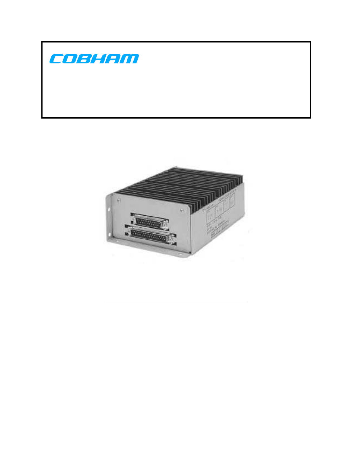
PASSENGER SPEAKER AMPLIFIER
1
INSTALLATION AND OPERATION MANUAL
REV "-" Sep 15, 2004
Cobham
6400 Wilkinson Drive
Prescott, AZ 86301-6164
(928) 708-1500
Amendment #2 Aug 9, 2011
CONFIDENTIAL AND PROPRIETARY TO COBHAM
Page 2

251-16-1 Rev. - 251 Passenger Speaker Amplifier Installation and Operation Manual
Cobham
has acquired the assets of Nothern Airborne
Technology Ltd. and dB Systems Inc., and
has reissued this manual in its entirety
Cobham
will be responsible for all future
amendments and revisions.
Aug 9, 2011 Page ii
ENG-FORM: 820-0109.DOT Amendment #2 Aug 9, 2011
CONFIDENTIAL AND PROPRIETARY TO COBHAM
Page 3

251-16-1 Rev. - 251 Passenger Speaker Amplifier Installation and Operation Manual
Amendment
Zack Pahlman
2011.08.16
11:01:10 -07'00'
Geoff
Melton
2011.08.16
14:45:47
-07'00'
Aaron
Voigt
(Approved
)
2011.08.1
6
16:23:14
-07'00'
Periodically Cobham will release manual amendments. In order to maintain the most
accurate and up to date manual these amendments should be carried out immediately
upon receipt and recorded on the following amendment record.
AMENDMENT RECORD
Amend
ment
Date
Amendment Change Check Approve
Number
1 Aug 3/07
2 Aug 9/11 Incorporated ECR11040.
Added 251-[ ] MOD F.
Insert any Amendment Instruction sheets after this page.
Aug 9, 2011 Page iii
ENG-FORM: 820-0109.DOT Amendment #2 Aug 9, 2011
CONFIDENTIAL AND PROPRIETARY TO COBHAM
Page 4
INSTALL_OPS
MANUAL AMENDMENT
Manual: 251-16-1 Amendment #: 2
Document #: 251-16-1 809-0002 Amendment Date: Aug 9, 2011
The purpose of this amendment is to update the 251 outline drawing and MOD table
per ECR11040.
Amendment Instructions:
1
2
2
Remove Pages Replace With Pages
Title Page Amendment # 1 Title Page Amendment # 2
Page ii Amendment # 1 Page ii Amendment # 2
Page iii Amendment # 1 Page iii Amendment # 2
Page b Amendment #1 Page b Amendment #2
Page c Amendment #1 Page c Amendment #2
Page d Amendment #1 Page d Amendment #2
Remove Drawings Replace With Drawings
251 Rev 1.51 (page 7) 251 Rev 1.70 (page 7)
Add Drawings After Drawings
251-003 810-0 Rev 1.30 Page 15
251-006 810-0 Rev 1.00 251-003 810-0 Rev 1.30
Note: Ensure that all drawings are inserted in the order shown on the latest drawing lists.
2 Update the Amendment Record sheet at the front of the manual.
3 Insert this page into the manual after the Amendment Record sheet (page iii).
Manual Amendment ends after the following amended pages
Amendment # 2 August 9, 2011 Page 1
ENG-FORM: 809-0109.DOT
CONFIDENTIAL AND PROPRIETARY TO COBHAM
Page 5

INSTALLATION & OPERATION
MANUAL AMENDMENT
Manual: SM251 251 Series Amendment #: 1
Document # SM251\Install_Ops\809-0001 Amendment Date: Aug 03, 2004
The purpose of this amendment is to correct the outline drawing and include the NAT
information.
Amendment Instructions:
1
Pages b – c, rev - Pages b – d, rev -, Amendment #1
Page 7 Page 7, Amendment #1
2
3
4 Update the Amendment Record sheet at the front of the manual.
5 Insert this page into the manual after the Amendment Record sheet (page iii).
Manual Amendment ends after the following amended pages
Remove Pages Replace With Pages
251-16-1 Title Page, rev - SM251 Title Page, rev -
Insert Pages After Page
Pages ii – iii SM251 Title Page
Add Section (to the end of the manual)
4.0 Supplements
Amendment #1 Aug 03, 2004 Page 1
ENG-FORM: 809-0107.DOT
PROPRIETARY AND CONFIDENTIAL TO NORTHERN AIRBORNE TECHNOLOGY LTD.
Page 6

EQUIPMENT MANUAL 251-16-1 REV -
CHANGE RECORD
DATE CHANGE CHECK APPROVAL
3-11-03
ORIGINAL DOCUMENT RELEASED
AP
ML
251/251-16-1 Amendment #1 Aug 03, 2004
Page a
Page 7

EQUIPMENT MANUAL 251-16-1 REV -
TABLE OF CONTENTS
Page
1.0 EQUIPMENT OPERATIONS AND INSTALLATION.................................................................1
2.0 SPECIFICATIONS ....................................................................................................................3
3.0 INSTALLATION PROCEDURES, WIRING DIAGRAM, AND LIMITATIONS............................6
3.1 PHYSICAL.................................................................................................................................6
3.2 ELECTRICAL ............................................................................................................................6
Tables
Table A Detail Part Numbers..........................................................................................................c
Table 1 Pinout Listing.....................................................................................................................9
Table 2 Environmental Qualification Form ...................................................................................14
Figures / Drawings
251 Outline, Model 251-[ ], Passenger Speaker Amplifier (Rev 1.70)....................................7
Figure 2 Model 251-[ ] Block Diagram...........................................................................................8
Figure 3 Model 251-[ ] Wiring Diagram .......................................................................................10
Figure 4 Internal Trim Pot Adjustments.........................................................................................13
251/251-16-1 Amendment #2 Aug 9, 2011 Page b
PROPRIETARY AND CONFIDENTIAL TO COBHAM
Page 8

EQUIPMENT MANUAL 251-16-1 REV -
MODEL 251 DETAIL PART NUMBER PROCEDURES AND LEVELS
The following is a tabulation of all detail part numbers available for the
Model 251 Passenger Speaker Amplifier. A Model 251 with an
associated detail part number is designated as a Model 251-XXX,
where XXX is the applicable three digit detail part number.
Table A. Detail Part Numbers
Detail Part No. Description of Detail
001 Low pass filters adjusted for -3 dB attenuation at 90 Hz on left and
right speaker outputs. High pass filters adjusted for -3 dB attenuation
at 20 Khz on left and right speaker outputs.
-001 calibration is designed for use with 4-inch speakers.
002 Identical to 251 Base Model. Part number 251-002 was created to
prevent a conflict with an existing part number 251 in customer part
system.
003 Identical to 251 Base Model with the following exceptions:
a) Briefing audio is to output through the right speaker only.
b) The receiver inputs and switches are not available.
c) The briefer switch input is externally grounded, disabling the
Stereo Left input and the Stereo Right input.
Installation information can be found in the 251-003 Installation and
Operation Manual Supplement.
006 Identical to 251 Base Model with the following exceptions:
a) The chime tones are routed to the PA sidetone audio output.
b) The chime tones are activated upon the activation of the PA
key.
Installation information can be found in the 251-006 Installation and
Operation Manual Supplement.
251/251-16-1 Amendment #2 Aug 9, 2011 Page c
PROPRIETARY AND CONFIDENTIAL TO COBHAM
Page 9

EQUIPMENT MANUAL 251-16-1 REV -
SM251 FIGURES
This page lists the drawings necessary for complete maintenance and troubleshooting.
The applicable serial numbers are shown in the right hand column.
Previously only the most current revision of each figure was included in this
manual. For these figures, the rev is listed as "N/A".
Table B. Figures with Applicable Serial Numbers
FIGURE/DWG REV. DESCRIPTION TYPE SERIAL #
251 1.70 Passenger Speaker Amplifier Outline All
2 N/A Passenger Speaker Amplifier Block Diagram All
3 N/A Passenger Speaker Amplifier Wiring Diagram All
4 N/A Passenger Speaker Amplifier Internal Trim Pot Adjustment All
251/251-16-1 Amendment #2 Aug 9, 2011 Page d
PROPRIETARY AND CONFIDENTIAL TO COBHAM
Page 10

EQUIPMENT MANUAL 251-16-1
EQUIPMENT MANUAL
MODEL 251
PASSENGER SPEAKER AMPLIFIER
1.0 EQUIPMENT OPERATIONS AND INSTALLATION
The Model 251 Passenger Speaker Amplifier is a r emotely controlled, electronic unit that operates
upon command from remote switches and potent iometers in the cockpit or cabin of the aircraft.
The Model 251 provides Seat Belt and No Smoking sign chime t ones, a Cabin Call ringer tone,
ADF, Pilot Select Comm. (PSC), Briefer, and Cabin Paging audio (all in mono) to the cabin
speakers. It also provides audio from an external AM/FM stereo receiver/cassette tape or CD
player (in stereo) to the cabin speakers and auxiliary monitor outputs.
The left and right speaker amplifier channels are each powered through separate internal fuses so
that a failure in one speaker channel will not disable the ot her speaker channel or the remaining
control circuitry. The left and right monitor outputs are powered from a third power supply circuit.
All inputs and operating modes are electronically switched. Ground sig nals, supplied by manual
switches in the cockpit, enable the electr onic switches in the Model 251. The circuit ry is arrang ed
to give audio priority to paging, briefer, and chimes; the PA MIC, BRIEF, and Seat Belt/No
Smoking chime switch signals mute t he Stereo Left, Stereo Right , ADF 1, ADF 2, PSC, and TV
audio inputs. PA, briefer, and chimes will automatically enable speakers even if the speaker
switch is off. Microphone bias current is available f r om the Model 251 for the PA MIC microphone
input.
Electronic attenuators are employed to control paging volume and master receiver (ADF 1, ADF 2,
PSC, and TV) volume. Each attenuator has approximately 30 dB (minimum) of range and is
controlled by a remote volume potentiometer. T he pots required are zero t o 10,000 ohms, linear
taper, and are electrically arranged to pr ovide maximum resistance for maximum volume. The
audio source (stereo tape cassette player, etc. ) for the Stereo Left and Right inputs should have
its own external volume control attenuator for the Stereo Input to Speaker and Monitor Output
audio channels. The left and right stereo inputs are fully floating (differential type).
A musical chime tone is provided to the cabin speakers to alert the passengers of a change in the
Fasten Seat Belt or No Smoking sign status. A Cabin Call ringer tone is also provided to the
cabin for a cockpit to cabin interc om system. The chime and ringer tones do not pass through
either of the electronic attenuators. Internal screwdriver potentiometer adjustments are
accessible, after r e m oval of the Model 251 end plate, to set the chime or ringer levels heard in the
passenger speakers.
Each left and r ight speaker amplifier output rating is 28 Watts int o 2 ohm s ( 30 Watts typical) or 49
Watt s into 1 ohm. Both speak er amplifier outputs are internally protected against open and short
circuits as well as over-temperature (>105°C). A r emote electronic ON/OFF switch for the left and
right speaker outputs is provided. A r em ote electronic speaker mute control is also provided. The
mute control can be connected to the aircraft’s Weight-On-Wheels switch to lower speaker
volume upon landing when lower cabin ambient noise levels are present and less speaker volume
is needed. The speaker mute control drops speaker level by approximately 1/2 (-6 dB) when
grounded.
Left and right stereo monitor outputs are provided for connecting to a cabin headphone amplifier
or headphone audio distribution system. The monitor outputs are line-level (1 V
outputs that carry the same audio signals as the speaker outputs. Unlike the speaker outputs, the
adjustable)
RMS
251/251-16-1
Page 1
Page 11

EQUIPMENT MANUAL 251-16-1
monitor outputs cannot be deselected or muted independently of the normal input switching
circuits.
The operating m odes of the Model 251 are established when either a gr ound (low) signal or a 12
to 32 VDC (high) signal is applied as listed below to the connector pin listed:
Control
Pin No.
Signal Identification Function
P50-16 Low ADF 1 Switch Connects ADF 1 input audio to left
and right speaker and monitor outputs.
P50-15 Low ADF 2 Switch Connects ADF 2 input audio to left
and right speaker and monitor outputs.
P50-14 Low PSC Switch Connects Pilot Select Comm (PSC) input
audio to left and right speaker and
monitor outputs.
P50-13 Low TV Switch Connects TV input audio to left and right
speaker and monitor outputs.
P50-5 Low Stereo Switch Connects stereo left and stereo right
input audio to left and right speaker
and monitor outputs, respectively.
P50-24 Low PA Key Connects PA MIC input audio to PA
sidetone, left and right speaker,
and monitor outputs. Opens ADF, PSC,
TV, and stereo input audio circuits.
P50-25 Low Briefer Switch Connects briefer input audio to PA sidetone,
left and right speaker, and monitor outputs.
Opens ADF, PSC, TV, and stereo
input audio circuits.
P50-31* High No Smoking Chime tone to left and right speaker
and monitor outputs. Opens ADF, TV,
PSC, and stereo inputs.
P50-32* High Seat Belt Chime tone to left and right speaker
and monitor outputs. Opens ADF, TV,
PSC, and stereo inputs.
P50-33 Low Cabin Call Ringer tone to left and right speaker
and monitor outputs.
P50-34 Low Hook Switch Disables ringer tone.
P60-8 Low Speaker Enable Enables left and right speaker outputs.
P60-3 Low Speaker Mute Mutes (lowers volume -6 dB) left and right
speaker outputs.
*An application or
removal of a High signal at pins P50- 31 and P50-32 will provide a chime tone at
left and right speaker outputs regardless of speaker enable status.
NOTE: P50-XX is a pin on the 37-pin connector, P50
P40-XX is a pin on the 25-pin connector, P40
P60-XX is a pin on the 9-pin connector, P60
All internal screwdriver potentiomet er adjustments of the Model 251 are set to factory standards.
If it is necessary to change a setting, refer to Section 4.0 of this manual.
251/251-16-1
Page 2
Page 12

EQUIPMENT MANUAL 251-16-1
The amplifiers are adjusted for acceptable listening output levels into the proper loads with ADF
receiver inputs of 7.75 V
of 1.00 V
and PA MIC input of 0.25 V
RMS
, stereo audio inputs of 0.45 V
RMS
position, these inputs will provide 7.5 V
. With the volume controls set to maximum volume
RMS
(28 watts) into 2 ohms at each speaker output. The
RMS
, PSC, TV, and Briefer audio inputs
RMS
ADF receiver input levels are achieved when receivers are set for 100 milliwatts into 600 ohms. If
levels are greatly exceeded at any of the inputs, the audio will become distorted due to peak
clipping and audio bleedthrough will occur. However, the amplifiers will not be damaged.
2.0 SPECIFICATIONS
Input specifications are expressed in volts RMS, rather than milliwatts, to avoid any
misunderstanding.
INPUTS
:
ADF: Two individual, switched audio inputs for ADF1 and ADF2.
Input level is 7.75 V
RMS
.
PSC: One switched audio input compatible with the Pilot Select COMM output of
dB Systems cockpit audio control amplifiers (such as Models 438 and 700), which
provides a 1.00 V
signal produced from a summation of selected COMM,
RMS
DME and MKR receivers. The PSC input can also be used for TV audio or other
similar audio.
TV: One switched audio input for TV (or other device). Input level is 1.00 V
RMS
.
STEREO
LEFT: One switched differential audio input for the left audio channel from an
AM/FM Stereo receiver/tape or CD deck (or other device). Input level is maximum
0.45 V
(at maximum source volume) and audio LO is not common to that
RMS
of other inputs.
STEREO
RIGHT: Same as stereo left, switched by the same control input as stereo left.
BRIEF: One switched audio input for automated cabin briefer audio. Input level is
1.00 V
RMS
.
PA MIC: The microphone input used for cabin paging audio supplies bias current and is
compatible with carbon and amplified dynamic microphones. Input level is
0.25 V
RMS
.
PAGING
VOLUME: Controls level of PA MIC and brief audio inputs to the PA sidetone and left and
right speaker outputs. Volume control range is 30 dB (minimum) controlled by
a 10,000-ohm, 1/2-Watt, linear pot. Maximum volume is with maximum resistance.
RECEIVER
VOLUME: Controls level of ADF, PSC and TV audio inputs to the left and right speaker
outputs. Volume control range is 30 dB (minimum) controlled by a 10,000-ohm,
1/2-Watt, linear pot. Maximum volume is with maximum resistance.
251/251-16-1
Page 3
Page 13

EQUIPMENT MANUAL 251-16-1
OUTPUTS
:
RIGHT
SPEAKER: The right speaker amplifier is designed for speech and music signals.
Rated power specification is the maximum power the amplifier can
continuously deliver into the maximum rated load without clipping.
Rated Power
Load
49 W 1 ohm (40 Watts typical)
28 W 2 ohms (30 Watts typical)
15 W 4 ohms (18 Watts typical)
LEFT
SPEAKER: Same as right speaker specification
RIGHT
MONITOR: This output will deliver up to 26 milliwatts into 600 ohms continuously.
Factory calibration is 1.6 mW (1 V
RMS
).
LEFT
MONITOR: Same as right monitor specification
PA SDTN: This output will deliver 6.7 milliwatts (2 V
) into 600 ohms continuously.
RMS
Rated and continuous power ratings are the same.
CHIME
TONE: Generated and supplied to left and right speaker and monitor outputs when
12 to 32 VDC is applied to or removed from connector pins P50-31 or P50-32.
A 790 Hz tone followed by a 610 Hz tone (2-tone, HI/LO) is factory set for 3.5 VPP
(at speaker outputs), adjustable from 1.0 to 6.9 VP-P and is also available at
monitor outputs.
RINGER
TONE: Generated and supplied to left and right speaker and monitor outputs
when a ground signal is applied to connector pin P50-33. Ringer tone is
700 +
75 Hz tone, ON for 1.8 +0.1 second, then OFF for 3.2 +0.1
second, repeating. Factory set for 1.5 VP-P (700 Hz component)
(at speaker outputs), adjustable from 0 to 5.2 VPP.
FREQUENCY
RESPONSE: Upper and lower frequency limits are adjustable. Stereo, ADF, TV, and
PSC inputs to speaker and monitor outputs are flat within 3 dB from 40 Hz to
20,000 Hz. All other inputs to speaker, monitor, or PA sidetone outputs flat within
3 dB from 300 Hz to 6,000 Hz.
HARMONIC
DISTORTION
(THD+N): Less than 0.30 percent distortion, for stereo and less than 1% for ADF, TV
and, PSC to all outputs (40 Hz to 20 Khz). Less than 3% for PA and briefer to
all outputs (300 Hz to 6 Khz).
251/251-16-1
Page 4
Page 14

EQUIPMENT MANUAL 251-16-1
ISOLATION BETWEEN
CHANNELS: 60 dB, minimum.
OUTPUT NOISE: Greater than 75 dB below rated, all outputs.
POWER SUPPLY: 28 VDC, 5 ampere maximum.
OPERATING TEMPERATURE: From -55 to +70°C. Thermal fold back of the speaker
outputs occurs if the heatsink temperature reaches 105°C.
OPERATING ALTITUDE: To 70,000 feet.
QUALIFIED TO:
FAR PART 2 1 , TS O-C50c [A2F2]-B A(CL)XXXXXXZ(BZ)AAATZ(XXC2)XX
RTCA DO-160C: Refer to Table 3, Environmental Qualification Form,
for test category informatio n .
251/251-16-1
Page 5
Page 15

EQUIPMENT MANUAL 251-16-1
3.0 INSTALLATION PROCEDURES, WIRING DIAGRAM, AND LIMITATIONS
3.1 PHYSICAL
Installation dimensions are shown on the Model 251 outline on Figure 1. The amplifier should be
mounted to a met al surface and it is necessary to ground the case to t he metal aircraf t structur e.
The case is finished with an electrically conductive film so it is not necessary to remove the film for
electrical bonding.
The Model 251 may be mounted in any position. No shock or vibration isolators are required.
3.2 ELECTRICAL
Connections to the Model 251 are made through three "D" subm iniature connectors. T he mating
connectors are manufactured by Positronics Industries, Inc. and the part numbers for the
complete connector assemblies are:
Connector
Positronics Part No.
P40 (25 pin) SD25F10JVLO
P50 (37 pin) SD37F10JVLO
P60 (9 pin) SD9F10JVLO
Numerical pin identifications are shown in this section. T he wiring diagram is shown on Figure 2.
Shielded wire must be used where indicated on the diagrams. AW G 22-24 size wire should be
used for all connections except those to the input power, power ground, and speaker amplifier
outputs where AWG 20 size should be used. Multiple power, ground, and speaker output pins are
provided to allow parallel connection of wiring. This reduces voltage drops (losses) acr oss the
wiring and provides the best audio performance.
The control switches shown will switch low current loads and should have a DC rating of 28 VDC.
Typical switches for this application include Alco MTA series.
251/251-16-1
Page 6
Page 16

Amendment #8 Page 7
Chelton Avionics, Inc
dba Wulfsberg Electronics Division
Prescott,AZ
B
Page 17

EQUIPMENT MANUAL 251-16-1
251/251-16-1
Figure 2. Block Diagram, Model 250-XXX
Passenger Speaker Amplifier
Page 8
Page 18

EQUIPMENT MANUAL 251-16-1
The paging and receiver volume control pots req uired are linear taper, zero to 10,000 ohms, 1/2
watt or greater. Electrically, the pot s are wired to provide maximum resistance to the Model 251
for full volume (fully clockwise rotation).
Table 1. Pin Identification
P40-1 (25-pin connector):
1 Left Spkr Out HI
2 Left Spkr Out HI
3 Left Spkr Out LO
4 Left Spkr Out LO
5 Left Spkr Out LO
6 28 VDC
7 28 VDC
8 28 VDC
9 Right Spkr Out LO
10 Right Spkr Out LO
11 Right Spkr Out LO
12 Right Spkr Out HI
13 Right Spkr Out HI
P50-1 (37-pin connector):
1 Audio Common (except stereo)
2 PA MIC HI
3 Paging Volume
4 Briefer Audio HI
5 Stereo Switch
6 Left Input HI
7 Left Input LO
8 Right Input LO
9 Right Input HI
10 No Connection
11 Receiver Volume Control
12 No connection
13 TV Switch
14 PSC Switch
15 ADF 2 Switch
16 ADF 1 Switch
17 ADF 1 Audio HI
18 TV Audio HI
19 PSC Audio HI
P60 (9-pin connector):
1 Right Monitor Output HI
2 Right Monitor Output LO
3 Speaker Mute
4 Left Monitor Output LO
5 Left Monitor Output HI
14 Left Spkr Out HI
15 No connection
16 No connection
17 Power Ground
18 Power Ground
19 Power Ground
20 Power Ground
21 28 VDC
22 Chassis Ground
23 No connection
24 No connection
25 Right Spkr Out HI
20 Audio Common (except stereo)
21 Audio Common (except stereo)
22 Audio Common (except stereo)
23 No connection
24 PA Key
25 Briefer Switch
26 No connection
27 Audio Common (except stereo)
28 Audio Common (except stereo)
29 Audio Common (except stereo)
30 No connection
31 Smoking Sign Switch
32 Seat Belt Sign Switch
33 Cabin Call Switch
34 Hook Switch
35 PA Sidetone HI
36 Audio Common (except stereo)
37 ADF 2 Audio HI
8 Speaker Enable
6, 7, 9/No Connection
251/251-16-1
Page 9
Page 19

EQUIPMENT MANUAL 251-16-1
251/251-16-1
Figure 3. Wiring Diagram
Page 10
Page 20

EQUIPMENT MANUAL 251-16-1
251/251-16-1
Figure 3. Wiring Diagram (continued)
Page 11
Page 21

EQUIPMENT MANUAL 251-16-1
251/251-16-1
Figure 3. Wiring Diagram (continued)
Page 12
Page 22

EQUIPMENT MANUAL 251-16-1
251/251-16-1
Figure 4. Internal Trim
Pot Adjustments
Page 13
Page 23

EQUIPMENT MANUAL 251-16-1
Table 2. Environmental Qualificatio n F o rm
NOMENCLATURE: Passenger Speaker Amplifier_____________________________________________________
TYPE/MODEL/PART NO.: Model 251-[ ]
MANUFACTURER'S SPECIFICATION AND/OR OTHER APPLICABLE SPECIFICATION: dB Systems’__________
Document No. 251-16-1, Equipment Manual _________________________________________________________
MANUFACTURER: dB Systems, Inc. ______________________________________________________________
ADDRESS: 2847 152nd Avenue N.E., Redmond, Washington 98052 __________________________________
CONDITIONS
TSO NUMBER: TSO-C50c _______________________________
DO-160C
SECTION/
PARAGRAPH
DESCRIPTION OF CONDUCTED TESTS
Temperature and altitude
Low temperature
High temperature
In-flight loss of cooling
Altitude
Decompression
Overpressure
Temperature variation 5.0
Humidity 6.0 Qualified to Category A requirements.
Operational shocks and
Crash safety
Operational shocks
Crash safety
Vibration 8.0 Qualified without shock mounts to Category L,
4.0
4.5.1
4.5.2
4.5.3
4.5.4
4.6.1
4.6.2
4.6.3
7.0
7.2
7.3
Equipment qualified to Category F2.
(see also temperature variation)
(see also temperature variation)
(see also temperature variation)
Equipment does not require special cooling
Qualified to +70,000 ft.
Equipment Category A2, except decompressed to
+55,000 ft.
Equipment qualified to Category A2
Qualified to Category B; combined with 4.5.1, 4.5.2
& 4.5.3.
Qualified without shock mounts per DO-160C,
paragraphs 7.2.1, 7.3.1, 7.3.2, & 7.3.2.2.
except extended curve 150-2,000 Hz 3g pk.
Qualified without shock mounts to Category C. No
change in critical frequencies during tests.
Explosion proofness 9.0 Equipment identified as Category X, no test
required.
Waterproofness 10.0 Equipment identified as Category X, no test
required.
Fluids susceptibility 11.0 Equipment identified as Category X, no test
required.
Sand and dust 12.0 Equipment identified as Category X, no test
required.
251/251-16-1
Page 14
Page 24

EQUIPMENT MANUAL 251-16-1
Table 2. Environmenta l Qu a lifica tio n F o rm (continued)
TYPE/MODEL/PART NO.: Model 251-[ ]
CONDITIONS
DO-160C
SECTION/
PARAGRAPH
Fungus resistance 13.0 Equipment identified as Category X, no test
Salt spray 14.0 Equipment identified as Category X, no test
Magnetic effect 15.0 Equipment is Class Z.
Power input 16.0
Voltage spike 17.0 Qualified to Category A.
DESCRIPTION OF CONDUCTED TESTS
required.
required.
Equipment qualified to Categories B and Z.
Audio frequency conducted
18.0 Qualified to Category A.
susceptibility
Induced signal susceptibility 19.0 Qualified to Category A.
Radio frequency susceptibility 20.0 Qualified to Category T.
Emission of radio frequency energy 21.0 Qualified to Category Z.
Lightning induced transient
22.0 Qualified to Category XXC2.
susceptibility
Lightning direct effects 23.0 Equipment identified as Category X, no test
required.
Icing 24.0 Equipment identified as Category X, no test
required.
Other Tests: Acceptance tests in accordance with dB Systems’ Acceptance Test Procedure 251-4 and
performance tests in accordance with RTCA Document DO-214, Section 2.8 were conducted on the Model 251
qualification test unit.
Remarks: Model 251-[ ] was qualified to the environmental test requirements of RTCA DO-160C by similarity to
Models 250-[ ] and 700-[ ].
For Model 250-[ ]:
-Tests of DO-160C, Sections 4.0 (paragraphs 4.5.1, 4.5.2, & 4.5.3), 5.0, 16.0, and 18.0 were conducted at
dB Systems, Inc. in Redmond, Washington.
-Tests of DO-160C, Sections 4.0 (paragraphs 4.6.2 & 4.6.3) and 20.0 (radiated susc.) were conducted at
Sundstrand Data Control Inc. in Redmond, Washington.
-Tests of DO-160C, Sections 4.0 (paragraph 4.6.1), 7.0, 8.0, 15.0, 17.0, 19.0, 20.0 (conducted susc.), 21.0,
and 22.0 were conducted at Eldec Corporation in Lynnwood, Washington.
For Model 700-[ ]:
-Tests of DO-160C, Sections 4.0 (paragraphs 4.5.1, 4.5.2 & 4.5.3), 5.0, 16.0 (except subparagraph 16.5.2.3 b),
and 18.0 were conducted at dB Systems, Inc. in Redmond, Washington.
-Tests of DO-160C, Sections 4.0 (paragraphs 4.6.1, 4.6.2 & 4.6.3), 7.0, 8.0, 15.0, 16.0 (subparagraph 16.5.2.3b),
17.0, 19.0, 20.0, 21.0 and 22.0 were conducted at Sundstrand Data Control, Inc. in Redmond, Washington.
- Tests of DO-160C, Section 6.0, were conducted at Eldec Corporation and meet requirements based on
similarity to Models 207 and 407.
251/251-16-1
Page 15
Page 25

INSTALLATION AND OPERATION
MANUAL SUPPLEMENT
NAT Part #: 251-003 Description: Passenger Speaker Amplifier
Document #: SM251\251-003\810-0 Rev: 1.30
This supplement contains installation and operation information that is unique to the
251-003 Passenger Speaker Amplifier. Installation and operation information
common to the 251 base unit can be found in SM251 Installation and Operation Manual.
1 Description
1.1 Functional/Cosmetic Changes
The 251-003 is identical to the 251 base model with the following exceptions.
a) Briefing audio is to output through the right speaker only.
b) The receiver inputs and switches are not available.
c) The briefer switch input is externally grounded, disabling the Stereo Left input and
the Stereo Right input.
d) The left stereo speaker gain is approximately doubled.
e) The speaker mute provides an 8 dB drop on the left speaker output.
2 Installation
For general Installation information and drawings, see Installation and Operation
Manual SM251. Select the appropriate revision of the drawing for the serial number of
the unit under consideration. The drawings specific to this derivative are listed below,
and can be found at the end of this supplement.
Oct 5, 2005 Page 1 of 2
ENG-FORM: 810-0105.DOT
CONFIDENTIAL AND PROPRIETARY TO NORTHERN AIRBORNE TECHNOLOGY LTD.
Page 26

251-003 Passenger Speaker Amplifier Manual Supplement Rev. 1.30
2.1 Installation Drawings
DRAWING REV. DESCRIPTION TYPE SERIAL #
251\003\403-0 1.00 Passenger Speaker Amplifier Interconnect All
251\003\403-1 1.00 Passenger Speaker Amplifier Interconnect All
251\003\403-2 1.00 Passenger Speaker Amplifier Interconnect All
251\003\405-0 1.00 Passenger Speaker Amplifier Connector Map All
3 Operation
For general Operation information, see Installation and Operation Manual SM251 with
the following exceptions:
a) Briefing audio is to output through the right speaker only.
b) The receiver inputs and switches are not available.
c) The briefer switch input is externally grounded, disabling the Stereo Left input and
the Stereo Right input.
d) The left stereo speaker gain is approximately doubled.
e) The speaker mute provides an 8 dB drop on the left speaker output.
End of Installation and Operation Manual Supplement
Page 2 of 2 Oct 5, 2005
ENG-FORM: 810-0105.DOT
CONFIDENTIAL AND PROPRIETARY TO NORTHERN AIRBORNE TECHNOLOGY LTD.
Page 27

Page 28

Page 29

Page 30

Page 31

251-006 Passenger Speaker Amplifier
SM251 Installation and Operation Manual Supplement
This supplement contains installation and operation information that is unique to the 251-006 Passenger
Speaker Amplifier. Installation and operation information common to the 251 base unit can be found in
the SM251 Equipment Manual.
Section 1 Description
The 251-006 Passenger Speaker Amplifier is identical to the 251 wi th the following exceptions:
a) The chime tones are routed to the PA sidetone audio output.
b) The chime tones are activated upon the activation of the PA key.
Section 2 Installation
For installation information and drawings, see SM251. Select the appropriate revision of the drawing for
the serial number of the unit. The drawings specific to this derivative are listed below and can be found at
the end of this supplement.
2.1 Installation Drawings
DOCUMENT REV. DESCRIPTION TYPE SERIAL NO.
251-006
251\006\403-0 1.00 Passenger Speaker Amplifier Interconnect 2414 and up
251\006\405-0 1.00 Passenger Speaker Amplifier Connector Map 2414 and up
Section 3 Operation
For operation information, see SM251 Section 3 with the following exceptions:
a) The chime tones are routed to the PA sidetone audio output.
b) The chime tones are activated upon the activation of the PA key.
Supplement ends
SM Supplement Rev: 1.00 May 13, 2009 Page 1
ENG-FORM: 810-0111.DOT
CONFIDENTIAL AND PROPRIETARY TO NORTHERN AIRBORNE TECHNOLOGY LTD.
Page 32

251-006 Passenger Speaker Amplifier
SM251 Installation and Operation Manual Supplement
This page intentionally left blank.
Page 2 May 13, 2009 SM Supplement Rev: 1.00
ENG-FORM: 810-0111.DOT
CONFIDENTIAL AND PROPRIETARY TO NORTHERN AIRBORNE TECHNOLOGY LTD.
Page 33

Page 34

Page 35

Page 36

 Loading...