

Page 1

The most important thing we build is trust
2201R Mobile Tester
SCPI Reference Guide
47090/323
Issue 5
Page 2

2201R Mobile Tester SCPI Reference Guide
© Aeroflex Limited
Longacres House, Six Hills Way
Stevenage SG1 2AN, UK
Tel: +44 (0) 1438 742200.
www.cobham.com/wireless
2201R Mobile Tester SCPI Reference Guide
47090/323
Issue 5
19 December 2016
Copyright © 2016 Aeroflex Limited. All rights reserved.
No part of this document may be reproduced or transmitted in any form or by any means, electronic or mechanical, including
photocopying, or recorded by any information storage or retrieval system, without permission in writing by Aeroflex Limited (trading
as Cobham Wireless and hereafter referred to throughout the document as ‘Cobham’).
47090/323
Copyright © 2016 Aeroflex Limited. All rights reserved.
2
Page 3

2201R Mobile Tester
SCPI Reference Guide
Notice
As we are always seeking to improve our products, the information in this document gives only a general indication
of the product capacity, performance and suitability, none of which shall form part of any contract. We reserve the
right to make design changes without notice.
Trademarks
Aeroflex is a registered trademark of Cobham plc, the parent company of Aeroflex Limited.
Specifications, terms and conditions are subject to change without notice. All trademarks and registered trademarks
are the property of their respective companies.
Glossary
API Application Programming Interface
BS Base Station
BSE Base Station Emulator
CR Change Request
DUT Device Under Test
eMLPP enhanced Multi Level Precedence and Pre-emption Service
GSM-R Global System for Mobile Communications — Railway
GUI Graphical User Interface
MS Mobile Station
PC Personal Computer
PHY Physical Layer
PPC Power PC
PTP Point-to-Point
PTT Push-To-Talk
RAT Radio Access Technology
REC Railway Emergency Call
SCPI Standard Commands for Programmable Instruments
SMS Short Message Service
TBA To Be Announced
TS Test Script
UE User Equipment
VGCS Voice Group Call Service
QNX A commercial Unix-like Real Time Operating System
2201R Mobile Tester SCPI Reference Guide
47090/323
Copyright © 2016 Aeroflex Limited. All rights reserved.
3
Page 4

Table of contents
About this guide . . . . . . . . . . . . . . . . . . . . . . . . . . . . . . . . . . . . . . . . . . . . . . . . . . . . . . . . . . . . . . . . . . . . . . . . 13
Purpose and scope. . . . . . . . . . . . . . . . . . . . . . . . . . . . . . . . . . . . . . . . . . . . . . . . . . . . . . . . . . . . . . . . . . . . . . . . . . . . . . . . . . . . . . . . . .14
Assumptions . . . . . . . . . . . . . . . . . . . . . . . . . . . . . . . . . . . . . . . . . . . . . . . . . . . . . . . . . . . . . . . . . . . . . . . . . . . . . . . . . . . . . . . . . . . . . . .14
Related information. . . . . . . . . . . . . . . . . . . . . . . . . . . . . . . . . . . . . . . . . . . . . . . . . . . . . . . . . . . . . . . . . . . . . . . . . . . . . . . . . . . . . . . . .14
Technical assistance . . . . . . . . . . . . . . . . . . . . . . . . . . . . . . . . . . . . . . . . . . . . . . . . . . . . . . . . . . . . . . . . . . . . . . . . . . . . . . . . . . . . . . . .14
Conventions . . . . . . . . . . . . . . . . . . . . . . . . . . . . . . . . . . . . . . . . . . . . . . . . . . . . . . . . . . . . . . . . . . . . . . . . . . . . . . . . . . . . . . . . . . . . . . .15
Chapter 1
Overview
About the 2201R Mobile Tester . . . . . . . . . . . . . . . . . . . . . . . . . . . . . . . . . . . . . . . . . . . . . . . . . . . . . . . . . . . . . . . . . . . . . . . . . . . . .17
About remote control of the 2201R Mobile Tester . . . . . . . . . . . . . . . . . . . . . . . . . . . . . . . . . . . . . . . . . . . . . . . . . . . . . . . . . . . .17
Chapter 2
Remote control of the 2201R Mobile Tester
Remote control applications and requirements . . . . . . . . . . . . . . . . . . . . . . . . . . . . . . . . . . . . . . . . . . . . . . . . . . . . . . . . . . . . . . .19
What SCPI is . . . . . . . . . . . . . . . . . . . . . . . . . . . . . . . . . . . . . . . . . . . . . . . . . . . . . . . . . . . . . . . . . . . . . . . . . . . . . . . . . . . . . . . . . . . . . . .19
SCPI command structure. . . . . . . . . . . . . . . . . . . . . . . . . . . . . . . . . . . . . . . . . . . . . . . . . . . . . . . . . . . . . . . . . . . . . . . . . . . . . . . . . . . .19
Syntax and notation . . . . . . . . . . . . . . . . . . . . . . . . . . . . . . . . . . . . . . . . . . . . . . . . . . . . . . . . . . . . . . . . . . . . . . . . . . . . . . . . . . . . . . . .20
Compound commands . . . . . . . . . . . . . . . . . . . . . . . . . . . . . . . . . . . . . . . . . . . . . . . . . . . . . . . . . . . . . . . . . . . . . . . . . . . . . . . . . .20
Parameters . . . . . . . . . . . . . . . . . . . . . . . . . . . . . . . . . . . . . . . . . . . . . . . . . . . . . . . . . . . . . . . . . . . . . . . . . . . . . . . . . . . . . . . . . . . . .20
Queries. . . . . . . . . . . . . . . . . . . . . . . . . . . . . . . . . . . . . . . . . . . . . . . . . . . . . . . . . . . . . . . . . . . . . . . . . . . . . . . . . . . . . . . . . . . . . . . . .21
Common commands. . . . . . . . . . . . . . . . . . . . . . . . . . . . . . . . . . . . . . . . . . . . . . . . . . . . . . . . . . . . . . . . . . . . . . . . . . . . . . . . . . . .21
SCPI notation . . . . . . . . . . . . . . . . . . . . . . . . . . . . . . . . . . . . . . . . . . . . . . . . . . . . . . . . . . . . . . . . . . . . . . . . . . . . . . . . . . . . . . . . . .22
Command subsystem overview. . . . . . . . . . . . . . . . . . . . . . . . . . . . . . . . . . . . . . . . . . . . . . . . . . . . . . . . . . . . . . . . . . . . . . . . . . . . . .23
Command commands . . . . . . . . . . . . . . . . . . . . . . . . . . . . . . . . . . . . . . . . . . . . . . . . . . . . . . . . . . . . . . . . . . . . . . . . . . . . . . . . . . . . . .24
The communication-related subsystems . . . . . . . . . . . . . . . . . . . . . . . . . . . . . . . . . . . . . . . . . . . . . . . . . . . . . . . . . . . . . . . . . . . . .25
The SYSTem subsystem . . . . . . . . . . . . . . . . . . . . . . . . . . . . . . . . . . . . . . . . . . . . . . . . . . . . . . . . . . . . . . . . . . . . . . . . . . . . . . . . .25
The STATus subsystem. . . . . . . . . . . . . . . . . . . . . . . . . . . . . . . . . . . . . . . . . . . . . . . . . . . . . . . . . . . . . . . . . . . . . . . . . . . . . . . . . .25
The FORMat subsystem – overview . . . . . . . . . . . . . . . . . . . . . . . . . . . . . . . . . . . . . . . . . . . . . . . . . . . . . . . . . . . . . . . . . . . . . .29
The base station and mobile station parameter subsystems . . . . . . . . . . . . . . . . . . . . . . . . . . . . . . . . . . . . . . . . . . . . . . . . . . .30
The CONFigure subsystem . . . . . . . . . . . . . . . . . . . . . . . . . . . . . . . . . . . . . . . . . . . . . . . . . . . . . . . . . . . . . . . . . . . . . . . . . . . . . .30
The CALL subsystem . . . . . . . . . . . . . . . . . . . . . . . . . . . . . . . . . . . . . . . . . . . . . . . . . . . . . . . . . . . . . . . . . . . . . . . . . . . . . . . . . . . .30
The Measurement subsystems . . . . . . . . . . . . . . . . . . . . . . . . . . . . . . . . . . . . . . . . . . . . . . . . . . . . . . . . . . . . . . . . . . . . . . . . . . . . . .31
The MEASure subsystem . . . . . . . . . . . . . . . . . . . . . . . . . . . . . . . . . . . . . . . . . . . . . . . . . . . . . . . . . . . . . . . . . . . . . . . . . . . . . . . .31
The FETCh subsystem. . . . . . . . . . . . . . . . . . . . . . . . . . . . . . . . . . . . . . . . . . . . . . . . . . . . . . . . . . . . . . . . . . . . . . . . . . . . . . . . . . .36
SCPI command errors. . . . . . . . . . . . . . . . . . . . . . . . . . . . . . . . . . . . . . . . . . . . . . . . . . . . . . . . . . . . . . . . . . . . . . . . . . . . . . . . . . . . . . .38
Chapter 3
Introduction to the SCPI command reference
SCPI command reference structure. . . . . . . . . . . . . . . . . . . . . . . . . . . . . . . . . . . . . . . . . . . . . . . . . . . . . . . . . . . . . . . . . . . . . . . . . .41
Command response on USB, RS-232 and TCP/IP. . . . . . . . . . . . . . . . . . . . . . . . . . . . . . . . . . . . . . . . . . . . . . . . . . . . . . . . . . . . . .41
Bluetooth commands . . . . . . . . . . . . . . . . . . . . . . . . . . . . . . . . . . . . . . . . . . . . . . . . . . . . . . . . . . . . . . . . . . . . . . . . . . . . . . . . . . . . . . .41
Signaling operation register group . . . . . . . . . . . . . . . . . . . . . . . . . . . . . . . . . . . . . . . . . . . . . . . . . . . . . . . . . . . . . . . . . . . . . . . . . . .41
Chapter 4
Common commands
Introduction . . . . . . . . . . . . . . . . . . . . . . . . . . . . . . . . . . . . . . . . . . . . . . . . . . . . . . . . . . . . . . . . . . . . . . . . . . . . . . . . . . . . . . . . . . . . . . .43
47090/323
Copyright © 2016 Aeroflex Limited. All rights reserved.
4
Page 5

2201R Mobile Tester SCPI Reference Guide
General common commands . . . . . . . . . . . . . . . . . . . . . . . . . . . . . . . . . . . . . . . . . . . . . . . . . . . . . . . . . . . . . . . . . . . . . . . . . . . . . . . .43
:REBoot . . . . . . . . . . . . . . . . . . . . . . . . . . . . . . . . . . . . . . . . . . . . . . . . . . . . . . . . . . . . . . . . . . . . . . . . . . . . . . . . . . . . . . . . . . . . . . . .43
*CAL? . . . . . . . . . . . . . . . . . . . . . . . . . . . . . . . . . . . . . . . . . . . . . . . . . . . . . . . . . . . . . . . . . . . . . . . . . . . . . . . . . . . . . . . . . . . . . . . . . .43
*CLS . . . . . . . . . . . . . . . . . . . . . . . . . . . . . . . . . . . . . . . . . . . . . . . . . . . . . . . . . . . . . . . . . . . . . . . . . . . . . . . . . . . . . . . . . . . . . . . . . . .44
*ESE . . . . . . . . . . . . . . . . . . . . . . . . . . . . . . . . . . . . . . . . . . . . . . . . . . . . . . . . . . . . . . . . . . . . . . . . . . . . . . . . . . . . . . . . . . . . . . . . . . .44
*ESR . . . . . . . . . . . . . . . . . . . . . . . . . . . . . . . . . . . . . . . . . . . . . . . . . . . . . . . . . . . . . . . . . . . . . . . . . . . . . . . . . . . . . . . . . . . . . . . . . . .45
*IDN? . . . . . . . . . . . . . . . . . . . . . . . . . . . . . . . . . . . . . . . . . . . . . . . . . . . . . . . . . . . . . . . . . . . . . . . . . . . . . . . . . . . . . . . . . . . . . . . . . .45
*OPT . . . . . . . . . . . . . . . . . . . . . . . . . . . . . . . . . . . . . . . . . . . . . . . . . . . . . . . . . . . . . . . . . . . . . . . . . . . . . . . . . . . . . . . . . . . . . . . . . . .46
*RST . . . . . . . . . . . . . . . . . . . . . . . . . . . . . . . . . . . . . . . . . . . . . . . . . . . . . . . . . . . . . . . . . . . . . . . . . . . . . . . . . . . . . . . . . . . . . . . . . . .46
*STB . . . . . . . . . . . . . . . . . . . . . . . . . . . . . . . . . . . . . . . . . . . . . . . . . . . . . . . . . . . . . . . . . . . . . . . . . . . . . . . . . . . . . . . . . . . . . . . . . . .47
*OPC? . . . . . . . . . . . . . . . . . . . . . . . . . . . . . . . . . . . . . . . . . . . . . . . . . . . . . . . . . . . . . . . . . . . . . . . . . . . . . . . . . . . . . . . . . . . . . . . . . .47
*SRE . . . . . . . . . . . . . . . . . . . . . . . . . . . . . . . . . . . . . . . . . . . . . . . . . . . . . . . . . . . . . . . . . . . . . . . . . . . . . . . . . . . . . . . . . . . . . . . . . . .48
The event status register . . . . . . . . . . . . . . . . . . . . . . . . . . . . . . . . . . . . . . . . . . . . . . . . . . . . . . . . . . . . . . . . . . . . . . . . . . . . . . . . . . . .49
The service register . . . . . . . . . . . . . . . . . . . . . . . . . . . . . . . . . . . . . . . . . . . . . . . . . . . . . . . . . . . . . . . . . . . . . . . . . . . . . . . . . . . . . . . . .50
Chapter 5
System commands
Introduction . . . . . . . . . . . . . . . . . . . . . . . . . . . . . . . . . . . . . . . . . . . . . . . . . . . . . . . . . . . . . . . . . . . . . . . . . . . . . . . . . . . . . . . . . . . . . . .52
System subsystem. . . . . . . . . . . . . . . . . . . . . . . . . . . . . . . . . . . . . . . . . . . . . . . . . . . . . . . . . . . . . . . . . . . . . . . . . . . . . . . . . . . . . . . . . .52
:SYSTem:ERRor[:NEXT]?. . . . . . . . . . . . . . . . . . . . . . . . . . . . . . . . . . . . . . . . . . . . . . . . . . . . . . . . . . . . . . . . . . . . . . . . . . . . . . . . . .52
:SYSTem:ERRor:COUNt? . . . . . . . . . . . . . . . . . . . . . . . . . . . . . . . . . . . . . . . . . . . . . . . . . . . . . . . . . . . . . . . . . . . . . . . . . . . . . . . . .52
:SYSTem:ERRor:CODE[:NEXT]?. . . . . . . . . . . . . . . . . . . . . . . . . . . . . . . . . . . . . . . . . . . . . . . . . . . . . . . . . . . . . . . . . . . . . . . . . . . .53
:SYSTem:ERRor:CODE:ALL? . . . . . . . . . . . . . . . . . . . . . . . . . . . . . . . . . . . . . . . . . . . . . . . . . . . . . . . . . . . . . . . . . . . . . . . . . . . . . . .53
:SYSTem:Message . . . . . . . . . . . . . . . . . . . . . . . . . . . . . . . . . . . . . . . . . . . . . . . . . . . . . . . . . . . . . . . . . . . . . . . . . . . . . . . . . . . . . . .54
:SYSTem:COMMunicate:LOCal . . . . . . . . . . . . . . . . . . . . . . . . . . . . . . . . . . . . . . . . . . . . . . . . . . . . . . . . . . . . . . . . . . . . . . . . . . .54
:SYSTem:COMMunicate:TCPip:ADDRess . . . . . . . . . . . . . . . . . . . . . . . . . . . . . . . . . . . . . . . . . . . . . . . . . . . . . . . . . . . . . . . . . .55
:SYSTem:COMMunicate:TCPip:NETMask. . . . . . . . . . . . . . . . . . . . . . . . . . . . . . . . . . . . . . . . . . . . . . . . . . . . . . . . . . . . . . . . . .55
:SYSTem:COMMunicate:TCPip:GATeway. . . . . . . . . . . . . . . . . . . . . . . . . . . . . . . . . . . . . . . . . . . . . . . . . . . . . . . . . . . . . . . . . .56
:SYSTem:COMMunicate:TCPip:PORT . . . . . . . . . . . . . . . . . . . . . . . . . . . . . . . . . . . . . . . . . . . . . . . . . . . . . . . . . . . . . . . . . . . . .56
:SYSTem:COMMunicate:TCPip:TERMinator . . . . . . . . . . . . . . . . . . . . . . . . . . . . . . . . . . . . . . . . . . . . . . . . . . . . . . . . . . . . . . .57
:SYSTem:COMMunicate:TCPip:MOUNt . . . . . . . . . . . . . . . . . . . . . . . . . . . . . . . . . . . . . . . . . . . . . . . . . . . . . . . . . . . . . . . . . . .57
:SYSTem:COMMunicate:TCPip:DHCP . . . . . . . . . . . . . . . . . . . . . . . . . . . . . . . . . . . . . . . . . . . . . . . . . . . . . . . . . . . . . . . . . . . . .58
:SYSTem:COMMunicate:TCPip:MACaddr?. . . . . . . . . . . . . . . . . . . . . . . . . . . . . . . . . . . . . . . . . . . . . . . . . . . . . . . . . . . . . . . . .58
:SYSTem:COMMunicate:SERA:REMote. . . . . . . . . . . . . . . . . . . . . . . . . . . . . . . . . . . . . . . . . . . . . . . . . . . . . . . . . . . . . . . . . . . .59
:SYSTem:COMMunicate:SERA:TERMinator . . . . . . . . . . . . . . . . . . . . . . . . . . . . . . . . . . . . . . . . . . . . . . . . . . . . . . . . . . . . . . . .59
:SYSTem:COMMunicate:SERB:TERMinator . . . . . . . . . . . . . . . . . . . . . . . . . . . . . . . . . . . . . . . . . . . . . . . . . . . . . . . . . . . . . . . .60
:SYSTem:DATE . . . . . . . . . . . . . . . . . . . . . . . . . . . . . . . . . . . . . . . . . . . . . . . . . . . . . . . . . . . . . . . . . . . . . . . . . . . . . . . . . . . . . . . . . .60
:SYSTem:TIME . . . . . . . . . . . . . . . . . . . . . . . . . . . . . . . . . . . . . . . . . . . . . . . . . . . . . . . . . . . . . . . . . . . . . . . . . . . . . . . . . . . . . . . . . .61
:SYSTem:SHUTdown . . . . . . . . . . . . . . . . . . . . . . . . . . . . . . . . . . . . . . . . . . . . . . . . . . . . . . . . . . . . . . . . . . . . . . . . . . . . . . . . . . . .61
Chapter 6
Status commands
Introduction . . . . . . . . . . . . . . . . . . . . . . . . . . . . . . . . . . . . . . . . . . . . . . . . . . . . . . . . . . . . . . . . . . . . . . . . . . . . . . . . . . . . . . . . . . . . . . .63
STATus commands . . . . . . . . . . . . . . . . . . . . . . . . . . . . . . . . . . . . . . . . . . . . . . . . . . . . . . . . . . . . . . . . . . . . . . . . . . . . . . . . . . . . . . . . .63
:STATus:PRESet . . . . . . . . . . . . . . . . . . . . . . . . . . . . . . . . . . . . . . . . . . . . . . . . . . . . . . . . . . . . . . . . . . . . . . . . . . . . . . . . . . . . . . . . .63
:STATus:OPERation[:EVENt]? . . . . . . . . . . . . . . . . . . . . . . . . . . . . . . . . . . . . . . . . . . . . . . . . . . . . . . . . . . . . . . . . . . . . . . . . . . . . .64
:STATus:OPERation:CONDition? . . . . . . . . . . . . . . . . . . . . . . . . . . . . . . . . . . . . . . . . . . . . . . . . . . . . . . . . . . . . . . . . . . . . . . . . . .64
:STATus:OPERation:ENABLe. . . . . . . . . . . . . . . . . . . . . . . . . . . . . . . . . . . . . . . . . . . . . . . . . . . . . . . . . . . . . . . . . . . . . . . . . . . . . .65
:STATus:OPERation:PTRansition . . . . . . . . . . . . . . . . . . . . . . . . . . . . . . . . . . . . . . . . . . . . . . . . . . . . . . . . . . . . . . . . . . . . . . . . . .65
:STATus:OPERation:NTRansition . . . . . . . . . . . . . . . . . . . . . . . . . . . . . . . . . . . . . . . . . . . . . . . . . . . . . . . . . . . . . . . . . . . . . . . . .66
:STATus:OPERation:SIGNalling:GSM[:EVENt]? . . . . . . . . . . . . . . . . . . . . . . . . . . . . . . . . . . . . . . . . . . . . . . . . . . . . . . . . . . . . .67
:STATus:OPERation:SIGNalling:GSM:CONDition? . . . . . . . . . . . . . . . . . . . . . . . . . . . . . . . . . . . . . . . . . . . . . . . . . . . . . . . . . .68
:STATus:OPERation:SIGNalling:GSM:ENABLe . . . . . . . . . . . . . . . . . . . . . . . . . . . . . . . . . . . . . . . . . . . . . . . . . . . . . . . . . . . . . .68
:STATus:OPERation:SIGNalling:GSM:PTRansition . . . . . . . . . . . . . . . . . . . . . . . . . . . . . . . . . . . . . . . . . . . . . . . . . . . . . . . . . .69
:STATus:OPERation:SIGNalling:GSM:NTRansition . . . . . . . . . . . . . . . . . . . . . . . . . . . . . . . . . . . . . . . . . . . . . . . . . . . . . . . . . .69
:STATus:OPERation:SIGNalling:GPRS[:EVENt]? . . . . . . . . . . . . . . . . . . . . . . . . . . . . . . . . . . . . . . . . . . . . . . . . . . . . . . . . . . . . .70
:STATus:OPERation:SIGNalling:GPRS:CONDition? . . . . . . . . . . . . . . . . . . . . . . . . . . . . . . . . . . . . . . . . . . . . . . . . . . . . . . . . . .71
:STATus:OPERation:SIGNalling:GPRS:ENABLe. . . . . . . . . . . . . . . . . . . . . . . . . . . . . . . . . . . . . . . . . . . . . . . . . . . . . . . . . . . . . .71
:STATus:OPERation:SIGNalling:GPRS:PTRansition. . . . . . . . . . . . . . . . . . . . . . . . . . . . . . . . . . . . . . . . . . . . . . . . . . . . . . . . . .72
47090/323
Copyright © 2016 Aeroflex Limited. All rights reserved.
5
Page 6

2201R Mobile Tester SCPI Reference Guide
:STATus:OPERation:SIGNalling:GPRS:NTRansition . . . . . . . . . . . . . . . . . . . . . . . . . . . . . . . . . . . . . . . . . . . . . . . . . . . . . . . . .72
:STATus:OPERation:SIGNalling:EGPRs[:EVENt]? . . . . . . . . . . . . . . . . . . . . . . . . . . . . . . . . . . . . . . . . . . . . . . . . . . . . . . . . . . . .73
:STATus:OPERation:SIGNalling:EGPRs:CONDition? . . . . . . . . . . . . . . . . . . . . . . . . . . . . . . . . . . . . . . . . . . . . . . . . . . . . . . . . .74
:STATus:OPERation:SIGNalling:EGPRs:ENABLe. . . . . . . . . . . . . . . . . . . . . . . . . . . . . . . . . . . . . . . . . . . . . . . . . . . . . . . . . . . . .74
:STATus:OPERation:SIGNalling:EGPRs:PTRansition . . . . . . . . . . . . . . . . . . . . . . . . . . . . . . . . . . . . . . . . . . . . . . . . . . . . . . . . .75
:STATus:OPERation:SIGNalling:EGPRs:NTRansition. . . . . . . . . . . . . . . . . . . . . . . . . . . . . . . . . . . . . . . . . . . . . . . . . . . . . . . . .75
:STATus:OPERation:MEASuring[:EVENt]?. . . . . . . . . . . . . . . . . . . . . . . . . . . . . . . . . . . . . . . . . . . . . . . . . . . . . . . . . . . . . . . . . .76
:STATus:OPERation:MEASuring:CONDition?. . . . . . . . . . . . . . . . . . . . . . . . . . . . . . . . . . . . . . . . . . . . . . . . . . . . . . . . . . . . . . .76
:STATus:OPERation:MEASuring:ENABLe. . . . . . . . . . . . . . . . . . . . . . . . . . . . . . . . . . . . . . . . . . . . . . . . . . . . . . . . . . . . . . . . . . .77
:STATus:OPERation:MEASuring:PTRansition. . . . . . . . . . . . . . . . . . . . . . . . . . . . . . . . . . . . . . . . . . . . . . . . . . . . . . . . . . . . . . .77
:STATus:OPERation:MEASuring:NTRansition . . . . . . . . . . . . . . . . . . . . . . . . . . . . . . . . . . . . . . . . . . . . . . . . . . . . . . . . . . . . . .78
Chapter 7
Format commands
Introduction . . . . . . . . . . . . . . . . . . . . . . . . . . . . . . . . . . . . . . . . . . . . . . . . . . . . . . . . . . . . . . . . . . . . . . . . . . . . . . . . . . . . . . . . . . . . . . .80
FORMat subsystem . . . . . . . . . . . . . . . . . . . . . . . . . . . . . . . . . . . . . . . . . . . . . . . . . . . . . . . . . . . . . . . . . . . . . . . . . . . . . . . . . . . . . . . . .80
FORMat:MRESult:STYPe . . . . . . . . . . . . . . . . . . . . . . . . . . . . . . . . . . . . . . . . . . . . . . . . . . . . . . . . . . . . . . . . . . . . . . . . . . . . . . . . .80
FORMat:MRESult:HEADer. . . . . . . . . . . . . . . . . . . . . . . . . . . . . . . . . . . . . . . . . . . . . . . . . . . . . . . . . . . . . . . . . . . . . . . . . . . . . . . .81
FORMat:ADELimiter. . . . . . . . . . . . . . . . . . . . . . . . . . . . . . . . . . . . . . . . . . . . . . . . . . . . . . . . . . . . . . . . . . . . . . . . . . . . . . . . . . . . .81
FORMat:RESolution . . . . . . . . . . . . . . . . . . . . . . . . . . . . . . . . . . . . . . . . . . . . . . . . . . . . . . . . . . . . . . . . . . . . . . . . . . . . . . . . . . . . .82
Chapter 8
Configuration commands
Introduction . . . . . . . . . . . . . . . . . . . . . . . . . . . . . . . . . . . . . . . . . . . . . . . . . . . . . . . . . . . . . . . . . . . . . . . . . . . . . . . . . . . . . . . . . . . . . . .84
General commands . . . . . . . . . . . . . . . . . . . . . . . . . . . . . . . . . . . . . . . . . . . . . . . . . . . . . . . . . . . . . . . . . . . . . . . . . . . . . . . . . . . . . . . . .85
:CONFigure:CSYStem. . . . . . . . . . . . . . . . . . . . . . . . . . . . . . . . . . . . . . . . . . . . . . . . . . . . . . . . . . . . . . . . . . . . . . . . . . . . . . . . . . . .85
CONFigure:CSYStem:HSPa. . . . . . . . . . . . . . . . . . . . . . . . . . . . . . . . . . . . . . . . . . . . . . . . . . . . . . . . . . . . . . . . . . . . . . . . . . . . . . .86
:CONFigure:COUPloss:STATe. . . . . . . . . . . . . . . . . . . . . . . . . . . . . . . . . . . . . . . . . . . . . . . . . . . . . . . . . . . . . . . . . . . . . . . . . . . . .86
:CONFigure:COUPloss:NAME. . . . . . . . . . . . . . . . . . . . . . . . . . . . . . . . . . . . . . . . . . . . . . . . . . . . . . . . . . . . . . . . . . . . . . . . . . . . .87
:CONFigure:COUPloss:DATA . . . . . . . . . . . . . . . . . . . . . . . . . . . . . . . . . . . . . . . . . . . . . . . . . . . . . . . . . . . . . . . . . . . . . . . . . . . . .88
Commands for the GSM option. . . . . . . . . . . . . . . . . . . . . . . . . . . . . . . . . . . . . . . . . . . . . . . . . . . . . . . . . . . . . . . . . . . . . . . . . . . . . .89
:CONFigure:GSM:TYPE. . . . . . . . . . . . . . . . . . . . . . . . . . . . . . . . . . . . . . . . . . . . . . . . . . . . . . . . . . . . . . . . . . . . . . . . . . . . . . . . . . .89
:CONFigure:GSM:ASSAll . . . . . . . . . . . . . . . . . . . . . . . . . . . . . . . . . . . . . . . . . . . . . . . . . . . . . . . . . . . . . . . . . . . . . . . . . . . . . . . . .90
:CONFigure:GSM:BS:LEVel . . . . . . . . . . . . . . . . . . . . . . . . . . . . . . . . . . . . . . . . . . . . . . . . . . . . . . . . . . . . . . . . . . . . . . . . . . . . . . .90
:CONFigure:GSM:BS:CMODe . . . . . . . . . . . . . . . . . . . . . . . . . . . . . . . . . . . . . . . . . . . . . . . . . . . . . . . . . . . . . . . . . . . . . . . . . . . . .91
:CONFigure:GSM:BS:LAI:MCC . . . . . . . . . . . . . . . . . . . . . . . . . . . . . . . . . . . . . . . . . . . . . . . . . . . . . . . . . . . . . . . . . . . . . . . . . . . .91
:CONFigure:GSM:BS:LAI:MNC[:DATA] . . . . . . . . . . . . . . . . . . . . . . . . . . . . . . . . . . . . . . . . . . . . . . . . . . . . . . . . . . . . . . . . . . . .92
:CONFigure:GSM:BS:LAI:MNC:FORM. . . . . . . . . . . . . . . . . . . . . . . . . . . . . . . . . . . . . . . . . . . . . . . . . . . . . . . . . . . . . . . . . . . . . .92
:CONFigure:GSM:BS:LAI:LAC . . . . . . . . . . . . . . . . . . . . . . . . . . . . . . . . . . . . . . . . . . . . . . . . . . . . . . . . . . . . . . . . . . . . . . . . . . . . .93
:CONFigure:GSM:BS:NCC . . . . . . . . . . . . . . . . . . . . . . . . . . . . . . . . . . . . . . . . . . . . . . . . . . . . . . . . . . . . . . . . . . . . . . . . . . . . . . . .93
:CONFigure:GSM:BS:BCC . . . . . . . . . . . . . . . . . . . . . . . . . . . . . . . . . . . . . . . . . . . . . . . . . . . . . . . . . . . . . . . . . . . . . . . . . . . . . . . .94
:CONFigure:GSM:BS:BCH:ARFCn . . . . . . . . . . . . . . . . . . . . . . . . . . . . . . . . . . . . . . . . . . . . . . . . . . . . . . . . . . . . . . . . . . . . . . . . .94
:CONFigure:GSM:BS:TCH:ARFCn . . . . . . . . . . . . . . . . . . . . . . . . . . . . . . . . . . . . . . . . . . . . . . . . . . . . . . . . . . . . . . . . . . . . . . . . .95
:CONFigure:GSM:BS:TCH:TYPE . . . . . . . . . . . . . . . . . . . . . . . . . . . . . . . . . . . . . . . . . . . . . . . . . . . . . . . . . . . . . . . . . . . . . . . . . . .95
:CONFigure:GSM:BS:CI . . . . . . . . . . . . . . . . . . . . . . . . . . . . . . . . . . . . . . . . . . . . . . . . . . . . . . . . . . . . . . . . . . . . . . . . . . . . . . . . . .96
:CONFigure:GSM:BS:CBA . . . . . . . . . . . . . . . . . . . . . . . . . . . . . . . . . . . . . . . . . . . . . . . . . . . . . . . . . . . . . . . . . . . . . . . . . . . . . . . .96
:CONFigure:GSM:BS:ATTach . . . . . . . . . . . . . . . . . . . . . . . . . . . . . . . . . . . . . . . . . . . . . . . . . . . . . . . . . . . . . . . . . . . . . . . . . . . . .97
:CONFigure:GSM:MSTAtion:DRX . . . . . . . . . . . . . . . . . . . . . . . . . . . . . . . . . . . . . . . . . . . . . . . . . . . . . . . . . . . . . . . . . . . . . . . . .97
:CONFigure:GSM:MSTAtion:TADVance . . . . . . . . . . . . . . . . . . . . . . . . . . . . . . . . . . . . . . . . . . . . . . . . . . . . . . . . . . . . . . . . . . .98
:CONFigure:GSM:MSTAtion:PLEVel[:ALL] . . . . . . . . . . . . . . . . . . . . . . . . . . . . . . . . . . . . . . . . . . . . . . . . . . . . . . . . . . . . . . . . . .98
:CONFigure:GSM:MSTAtion:MODE . . . . . . . . . . . . . . . . . . . . . . . . . . . . . . . . . . . . . . . . . . . . . . . . . . . . . . . . . . . . . . . . . . . . . . .99
:CONFigure:GSM:BER:LOOP . . . . . . . . . . . . . . . . . . . . . . . . . . . . . . . . . . . . . . . . . . . . . . . . . . . . . . . . . . . . . . . . . . . . . . . . . . . . . .99
:CONFigure:GSM:BER:BITPattern . . . . . . . . . . . . . . . . . . . . . . . . . . . . . . . . . . . . . . . . . . . . . . . . . . . . . . . . . . . . . . . . . . . . . . . . .100
:CONFigure:GSM:BER:COUNt . . . . . . . . . . . . . . . . . . . . . . . . . . . . . . . . . . . . . . . . . . . . . . . . . . . . . . . . . . . . . . . . . . . . . . . . . . . .101
:CONFigure:GSM:BER:RTDelay . . . . . . . . . . . . . . . . . . . . . . . . . . . . . . . . . . . . . . . . . . . . . . . . . . . . . . . . . . . . . . . . . . . . . . . . . . .101
:CONFigure:GSM:VLDelay. . . . . . . . . . . . . . . . . . . . . . . . . . . . . . . . . . . . . . . . . . . . . . . . . . . . . . . . . . . . . . . . . . . . . . . . . . . . . . . .102
:CONFigure:GSM:SMS:MCLass . . . . . . . . . . . . . . . . . . . . . . . . . . . . . . . . . . . . . . . . . . . . . . . . . . . . . . . . . . . . . . . . . . . . . . . . . . .102
:CONFigure:GSM:MEASure:GROUp[:RFTX] . . . . . . . . . . . . . . . . . . . . . . . . . . . . . . . . . . . . . . . . . . . . . . . . . . . . . . . . . . . . . . . .103
:CONFigure:GSM:SS:SSTatus . . . . . . . . . . . . . . . . . . . . . . . . . . . . . . . . . . . . . . . . . . . . . . . . . . . . . . . . . . . . . . . . . . . . . . . . . . . . .104
47090/323
Copyright © 2016 Aeroflex Limited. All rights reserved.
6
Page 7

2201R Mobile Tester SCPI Reference Guide
CONF:GSM:AUD:GEN . . . . . . . . . . . . . . . . . . . . . . . . . . . . . . . . . . . . . . . . . . . . . . . . . . . . . . . . . . . . . . . . . . . . . . . . . . . . . . . . . . .105
Commands for the GSM-R option. . . . . . . . . . . . . . . . . . . . . . . . . . . . . . . . . . . . . . . . . . . . . . . . . . . . . . . . . . . . . . . . . . . . . . . . . . . .106
:CONFigure:GSMR:VGCS:GID . . . . . . . . . . . . . . . . . . . . . . . . . . . . . . . . . . . . . . . . . . . . . . . . . . . . . . . . . . . . . . . . . . . . . . . . . . . .106
:CONFigure:GSMR:VGCS:CPRI. . . . . . . . . . . . . . . . . . . . . . . . . . . . . . . . . . . . . . . . . . . . . . . . . . . . . . . . . . . . . . . . . . . . . . . . . . . .107
CONF:GSMR:VGCS:AUDio:LOOPback . . . . . . . . . . . . . . . . . . . . . . . . . . . . . . . . . . . . . . . . . . . . . . . . . . . . . . . . . . . . . . . . . . . . .108
:CONFigure:USSD:USTA . . . . . . . . . . . . . . . . . . . . . . . . . . . . . . . . . . . . . . . . . . . . . . . . . . . . . . . . . . . . . . . . . . . . . . . . . . . . . . . . .109
:CONFigure:USSD:FNUM . . . . . . . . . . . . . . . . . . . . . . . . . . . . . . . . . . . . . . . . . . . . . . . . . . . . . . . . . . . . . . . . . . . . . . . . . . . . . . . .110
:CONFigure:GSMR:VGCS:UTOUinfo?. . . . . . . . . . . . . . . . . . . . . . . . . . . . . . . . . . . . . . . . . . . . . . . . . . . . . . . . . . . . . . . . . . . . . .110
Commands for the GPRS option . . . . . . . . . . . . . . . . . . . . . . . . . . . . . . . . . . . . . . . . . . . . . . . . . . . . . . . . . . . . . . . . . . . . . . . . . . . . .111
:CONFigure:GPRS:BS:RCL . . . . . . . . . . . . . . . . . . . . . . . . . . . . . . . . . . . . . . . . . . . . . . . . . . . . . . . . . . . . . . . . . . . . . . . . . . . . . . . .111
:CONFigure:GPRS:BS:RCO. . . . . . . . . . . . . . . . . . . . . . . . . . . . . . . . . . . . . . . . . . . . . . . . . . . . . . . . . . . . . . . . . . . . . . . . . . . . . . . .111
:CONFigure:GPRS:BS:ALPHa. . . . . . . . . . . . . . . . . . . . . . . . . . . . . . . . . . . . . . . . . . . . . . . . . . . . . . . . . . . . . . . . . . . . . . . . . . . . . .112
:CONFigure:GPRS:BS:RLCMac:USF. . . . . . . . . . . . . . . . . . . . . . . . . . . . . . . . . . . . . . . . . . . . . . . . . . . . . . . . . . . . . . . . . . . . . . . .112
:CONFigure:GPRS:BS:RLCMac:USF:INC. . . . . . . . . . . . . . . . . . . . . . . . . . . . . . . . . . . . . . . . . . . . . . . . . . . . . . . . . . . . . . . . . . . .113
:CONFigure:GPRS:BS:RLCMac:RRBP[:DATA] . . . . . . . . . . . . . . . . . . . . . . . . . . . . . . . . . . . . . . . . . . . . . . . . . . . . . . . . . . . . . . .113
:CONFigure:GPRS:BS:RLCMac:RRBP:MODE . . . . . . . . . . . . . . . . . . . . . . . . . . . . . . . . . . . . . . . . . . . . . . . . . . . . . . . . . . . . . . . .114
:CONFigure:GPRS:BS:RLCMac:PR . . . . . . . . . . . . . . . . . . . . . . . . . . . . . . . . . . . . . . . . . . . . . . . . . . . . . . . . . . . . . . . . . . . . . . . . .114
:CONFigure:GPRS:BS:RLCMac:TFI. . . . . . . . . . . . . . . . . . . . . . . . . . . . . . . . . . . . . . . . . . . . . . . . . . . . . . . . . . . . . . . . . . . . . . . . .115
:CONFigure:GPRS:BS:RLCMac:BSN[:DATA] . . . . . . . . . . . . . . . . . . . . . . . . . . . . . . . . . . . . . . . . . . . . . . . . . . . . . . . . . . . . . . . .115
:CONFigure:GPRS:BS:RLCMac:BSN:INC. . . . . . . . . . . . . . . . . . . . . . . . . . . . . . . . . . . . . . . . . . . . . . . . . . . . . . . . . . . . . . . . . . . .116
:CONFigure:GPRS:BS:ATTach . . . . . . . . . . . . . . . . . . . . . . . . . . . . . . . . . . . . . . . . . . . . . . . . . . . . . . . . . . . . . . . . . . . . . . . . . . . . .116
:CONFigure:GPRS:BS:MSTAtion:MSLot. . . . . . . . . . . . . . . . . . . . . . . . . . . . . . . . . . . . . . . . . . . . . . . . . . . . . . . . . . . . . . . . . . . .117
:CONFigure:GPRS:BS:BCC . . . . . . . . . . . . . . . . . . . . . . . . . . . . . . . . . . . . . . . . . . . . . . . . . . . . . . . . . . . . . . . . . . . . . . . . . . . . . . . .117
:CONFigure:GPRS:BS:BCH:ARFCn . . . . . . . . . . . . . . . . . . . . . . . . . . . . . . . . . . . . . . . . . . . . . . . . . . . . . . . . . . . . . . . . . . . . . . . . .118
:CONFigure:GPRS:BS:CBA . . . . . . . . . . . . . . . . . . . . . . . . . . . . . . . . . . . . . . . . . . . . . . . . . . . . . . . . . . . . . . . . . . . . . . . . . . . . . . . .118
:CONFigure:GPRS:BS:CI. . . . . . . . . . . . . . . . . . . . . . . . . . . . . . . . . . . . . . . . . . . . . . . . . . . . . . . . . . . . . . . . . . . . . . . . . . . . . . . . . .119
:CONFigure:GPRS:BS:LAI:MCC. . . . . . . . . . . . . . . . . . . . . . . . . . . . . . . . . . . . . . . . . . . . . . . . . . . . . . . . . . . . . . . . . . . . . . . . . . . .119
:CONFigure:GPRS:BS:LAI:MNC . . . . . . . . . . . . . . . . . . . . . . . . . . . . . . . . . . . . . . . . . . . . . . . . . . . . . . . . . . . . . . . . . . . . . . . . . . .120
:CONFigure:GPRS:BS:LAI:MNC:FORMat . . . . . . . . . . . . . . . . . . . . . . . . . . . . . . . . . . . . . . . . . . . . . . . . . . . . . . . . . . . . . . . . . . .120
:CONFigure:GPRS:BS:LAI:LAC . . . . . . . . . . . . . . . . . . . . . . . . . . . . . . . . . . . . . . . . . . . . . . . . . . . . . . . . . . . . . . . . . . . . . . . . . . . .121
:CONFigure:GPRS:BS:LEVel . . . . . . . . . . . . . . . . . . . . . . . . . . . . . . . . . . . . . . . . . . . . . . . . . . . . . . . . . . . . . . . . . . . . . . . . . . . . . . .121
:CONFigure:GPRS:BS:MSLot[:DATA] . . . . . . . . . . . . . . . . . . . . . . . . . . . . . . . . . . . . . . . . . . . . . . . . . . . . . . . . . . . . . . . . . . . . . .122
:CONFigure:GPRS:BS:MSLot:LEVel[:DATA]. . . . . . . . . . . . . . . . . . . . . . . . . . . . . . . . . . . . . . . . . . . . . . . . . . . . . . . . . . . . . . . . .122
:CONFigure:GPRS:BS:MSLot:LEVel:UNUSed. . . . . . . . . . . . . . . . . . . . . . . . . . . . . . . . . . . . . . . . . . . . . . . . . . . . . . . . . . . . . . . .123
:CONFigure:GPRS:BS:NCC. . . . . . . . . . . . . . . . . . . . . . . . . . . . . . . . . . . . . . . . . . . . . . . . . . . . . . . . . . . . . . . . . . . . . . . . . . . . . . . .123
:CONFigure:GPRS:BS:NCELl . . . . . . . . . . . . . . . . . . . . . . . . . . . . . . . . . . . . . . . . . . . . . . . . . . . . . . . . . . . . . . . . . . . . . . . . . . . . . .124
:CONFigure:GPRS:BS:ORIGinate . . . . . . . . . . . . . . . . . . . . . . . . . . . . . . . . . . . . . . . . . . . . . . . . . . . . . . . . . . . . . . . . . . . . . . . . . .125
:CONFigure:GPRS:BS:PDTCh:ARFCn . . . . . . . . . . . . . . . . . . . . . . . . . . . . . . . . . . . . . . . . . . . . . . . . . . . . . . . . . . . . . . . . . . . . . .125
:CONFigure:GPRS:BS:TCH:ARFCn . . . . . . . . . . . . . . . . . . . . . . . . . . . . . . . . . . . . . . . . . . . . . . . . . . . . . . . . . . . . . . . . . . . . . . . . .126
:CONFigure:GPRS:BS:TCH:TSLot. . . . . . . . . . . . . . . . . . . . . . . . . . . . . . . . . . . . . . . . . . . . . . . . . . . . . . . . . . . . . . . . . . . . . . . . . .126
:CONFigure:GPRS:BS:TCH:TYPE. . . . . . . . . . . . . . . . . . . . . . . . . . . . . . . . . . . . . . . . . . . . . . . . . . . . . . . . . . . . . . . . . . . . . . . . . . .127
:CONFigure:GPRS:BLER:COUNt . . . . . . . . . . . . . . . . . . . . . . . . . . . . . . . . . . . . . . . . . . . . . . . . . . . . . . . . . . . . . . . . . . . . . . . . . . .127
:CONFigure:GPRS:BLER:PDUCount. . . . . . . . . . . . . . . . . . . . . . . . . . . . . . . . . . . . . . . . . . . . . . . . . . . . . . . . . . . . . . . . . . . . . . . .128
:CONFigure:GPRS:BER:LOOP. . . . . . . . . . . . . . . . . . . . . . . . . . . . . . . . . . . . . . . . . . . . . . . . . . . . . . . . . . . . . . . . . . . . . . . . . . . . . .128
:CONFigure:GPRS:BER:BITPattern. . . . . . . . . . . . . . . . . . . . . . . . . . . . . . . . . . . . . . . . . . . . . . . . . . . . . . . . . . . . . . . . . . . . . . . . .129
:CONFigure:GPRS:BER:COUNt . . . . . . . . . . . . . . . . . . . . . . . . . . . . . . . . . . . . . . . . . . . . . . . . . . . . . . . . . . . . . . . . . . . . . . . . . . . .130
:CONFigure:GPRS:BER:RTDelay. . . . . . . . . . . . . . . . . . . . . . . . . . . . . . . . . . . . . . . . . . . . . . . . . . . . . . . . . . . . . . . . . . . . . . . . . . .130
:CONFigure:GPRS:BER:RSIGnalling:BITPattern . . . . . . . . . . . . . . . . . . . . . . . . . . . . . . . . . . . . . . . . . . . . . . . . . . . . . . . . . . . . .131
:CONFigure:GPRS:BER:RSIGnalling:COUNt. . . . . . . . . . . . . . . . . . . . . . . . . . . . . . . . . . . . . . . . . . . . . . . . . . . . . . . . . . . . . . . . .131
:CONFigure:GPRS:MSTAtion:DRX. . . . . . . . . . . . . . . . . . . . . . . . . . . . . . . . . . . . . . . . . . . . . . . . . .
:CONFigure:GPRS:MSTAtion:TADVance. . . . . . . . . . . . . . . . . . . . . . . . . . . . . . . . . . . . . . . . . . . . . . . . . . . . . . . . . . . . . . . . . . .132
:CONFigure:GPRS:MSTAtion:PLEVel[:ALL] . . . . . . . . . . . . . . . . . . . . . . . . . . . . . . . . . . . . . . . . . . . . . . . . . . . . . . . . . . . . . . . . .133
:CONFigure:GPRS:MSTAtion:MODE. . . . . . . . . . . . . . . . . . . . . . . . . . . . . . . . . . . . . . . . . . . . . . . . . . . . . . . . . . . . . . . . . . . . . . .133
:CONFigure:GPRS:MSTAtion:MSLot. . . . . . . . . . . . . . . . . . . . . . . . . . . . . . . . . . . . . . . . . . . . . . . . . . . . . . . . . . . . . . . . . . . . . . .134
:CONFigure:GPRS:MSTAtion:PSLots . . . . . . . . . . . . . . . . . . . . . . . . . . . . . . . . . . . . . . . . . . . . . . . . . . . . . . . . . . . . . . . . . . . . . .134
:CONFigure:GPRS:TYPE . . . . . . . . . . . . . . . . . . . . . . . . . . . . . . . . . . . . . . . . . . . . . . . . . . . . . . . . . . . . . . . . . . . . . . . . . . . . . . . . . .135
:CONFigure:GPRS:SMS:MCLass. . . . . . . . . . . . . . . . . . . . . . . . . . . . . . . . . . . . . . . . . . . . . . . . . . . . . . . . . . . . . . . . . . . . . . . . . . .135
:CONFigure:GPRS:MEASure:GROUp[:RFTX]. . . . . . . . . . . . . . . . . . . . . . . . . . . . . . . . . . . . . . . . . . . . . . . . . . . . . . . . . . . . . . . .136
:CONFigure:GPRS:IDREquest . . . . . . . . . . . . . . . . . . . . . . . . . . . . . . . . . . . . . . . . . . . . . . . . . . . . . . . . . . . . . . . . . . . . . . . . . . . . .137
Commands for the EDGE option . . . . . . . . . . . . . . . . . . . . . . . . . . . . . . . . . . . . . . . . . . . . . . . . . . . . . . . . . . . . . . . . . . . . . . . . . . . . .138
. . . . . . . . . . . . . . . . . . . . . . .132
47090/323
Copyright © 2016 Aeroflex Limited. All rights reserved.
7
Page 8

2201R Mobile Tester SCPI Reference Guide
:CONFigure:EGPRs:BS:RCL. . . . . . . . . . . . . . . . . . . . . . . . . . . . . . . . . . . . . . . . . . . . . . . . . . . . . . . . . . . . . . . . . . . . . . . . . . . . . . . .138
:CONFigure:EGPRs:BS:RCO . . . . . . . . . . . . . . . . . . . . . . . . . . . . . . . . . . . . . . . . . . . . . . . . . . . . . . . . . . . . . . . . . . . . . . . . . . . . . . .138
:CONFigure:EGPRs:BS:ALPHa . . . . . . . . . . . . . . . . . . . . . . . . . . . . . . . . . . . . . . . . . . . . . . . . . . . . . . . . . . . . . . . . . . . . . . . . . . . . .139
:CONFigure:EGPRs:BS:RLCMac:USF . . . . . . . . . . . . . . . . . . . . . . . . . . . . . . . . . . . . . . . . . . . . . . . . . . . . . . . . . . . . . . . . . . . . . . .139
:CONFigure:EGPRs:BS:RLCMac:USF:INC. . . . . . . . . . . . . . . . . . . . . . . . . . . . . . . . . . . . . . . . . . . . . . . . . . . . . . . . . . . . . . . . . . .140
:CONFigure:EGPRs:BS:RLCMac:RRBP[:DATA]. . . . . . . . . . . . . . . . . . . . . . . . . . . . . . . . . . . . . . . . . . . . . . . . . . . . . . . . . . . . . . .140
:CONFigure:EGPRs:BS:RLCMac:RRBP:MODE . . . . . . . . . . . . . . . . . . . . . . . . . . . . . . . . . . . . . . . . . . . . . . . . . . . . . . . . . . . . . . .141
:CONFigure:EGPRs:BS:RLCMac:PR. . . . . . . . . . . . . . . . . . . . . . . . . . . . . . . . . . . . . . . . . . . . . . . . . . . . . . . . . . . . . . . . . . . . . . . . .141
:CONFigure:EGPRs:BS:RLCMac:TFI. . . . . . . . . . . . . . . . . . . . . . . . . . . . . . . . . . . . . . . . . . . . . . . . . . . . . . . . . . . . . . . . . . . . . . . .142
:CONFigure:EGPRs:BS:RLCMac:BSN[:DATA] . . . . . . . . . . . . . . . . . . . . . . . . . . . . . . . . . . . . . . . . . . . . . . . . . . . . . . . . . . . . . . .142
:CONFigure:EGPRs:BS:RLCMac:BSN:INC. . . . . . . . . . . . . . . . . . . . . . . . . . . . . . . . . . . . . . . . . . . . . . . . . . . . . . . . . . . . . . . . . . .143
:CONFigure:EGPRs:BS:ATTach . . . . . . . . . . . . . . . . . . . . . . . . . . . . . . . . . . . . . . . . . . . . . . . . . . . . . . . . . . . . . . . . . . . . . . . . . . . .143
:CONFigure:EGPRs:BS:MSTAtion:MSLot. . . . . . . . . . . . . . . . . . . . . . . . . . . . . . . . . . . . . . . . . . . . . . . . . . . . . . . . . . . . . . . . . . .144
:CONFigure:EGPRs:BS:BCC . . . . . . . . . . . . . . . . . . . . . . . . . . . . . . . . . . . . . . . . . . . . . . . . . . . . . . . . . . . . . . . . . . . . . . . . . . . . . . .144
:CONFigure:EGPRs:BS:BCH:ARFCn . . . . . . . . . . . . . . . . . . . . . . . . . . . . . . . . . . . . . . . . . . . . . . . . . . . . . . . . . . . . . . . . . . . . . . . .145
:CONFigure:EGPRs:BS:CBA . . . . . . . . . . . . . . . . . . . . . . . . . . . . . . . . . . . . . . . . . . . . . . . . . . . . . . . . . . . . . . . . . . . . . . . . . . . . . . .145
:CONFigure:EGPRs:BS:CI . . . . . . . . . . . . . . . . . . . . . . . . . . . . . . . . . . . . . . . . . . . . . . . . . . . . . . . . . . . . . . . . . . . . . . . . . . . . . . . . .146
:CONFigure:EGPRs:BS:LAI:MCC. . . . . . . . . . . . . . . . . . . . . . . . . . . . . . . . . . . . . . . . . . . . . . . . . . . . . . . . . . . . . . . . . . . . . . . . . . .146
:CONFigure:EGPRs:BS:LAI:MNC. . . . . . . . . . . . . . . . . . . . . . . . . . . . . . . . . . . . . . . . . . . . . . . . . . . . . . . . . . . . . . . . . . . . . . . . . . .147
:CONFigure:EGPRs:BS:LAI:MNC:FORMat . . . . . . . . . . . . . . . . . . . . . . . . . . . . . . . . . . . . . . . . . . . . . . . . . . . . . . . . . . . . . . . . . .147
:CONFigure:EGPRs:BS:LAI:LAC. . . . . . . . . . . . . . . . . . . . . . . . . . . . . . . . . . . . . . . . . . . . . . . . . . . . . . . . . . . . . . . . . . . . . . . . . . . .148
:CONFigure:EGPRs:BS:LEVel . . . . . . . . . . . . . . . . . . . . . . . . . . . . . . . . . . . . . . . . . . . . . . . . . . . . . . . . . . . . . . . . . . . . . . . . . . . . . .148
:CONFigure:EGPRs:BS:MSLot[:DATA] . . . . . . . . . . . . . . . . . . . . . . . . . . . . . . . . . . . . . . . . . . . . . . . . . . . . . . . . . . . . . . . . . . . . .149
:CONFigure:EGPRs:BS:MSLot:LEVel[:DATA] . . . . . . . . . . . . . . . . . . . . . . . . . . . . . . . . . . . . . . . . . . . . . . . . . . . . . . . . . . . . . . . .149
:CONFigure:EGPRs:BS:MSLot:LEVel:UNUSed. . . . . . . . . . . . . . . . . . . . . . . . . . . . . . . . . . . . . . . . . . . . . . . . . . . . . . . . . . . . . . .150
:CONFigure:EGPRs:BS:NCC. . . . . . . . . . . . . . . . . . . . . . . . . . . . . . . . . . . . . . . . . . . . . . . . . . . . . . . . . . . . . . . . . . . . . . . . . . . . . . .150
:CONFigure:EGPRs:BS:NCELl. . . . . . . . . . . . . . . . . . . . . . . . . . . . . . . . . . . . . . . . . . . . . . . . . . . . . . . . . . . . . . . . . . . . . . . . . . . . . .151
:CONFigure:EGPRs:BS:ORIGinate . . . . . . . . . . . . . . . . . . . . . . . . . . . . . . . . . . . . . . . . . . . . . . . . . . . . . . . . . . . . . . . . . . . . . . . . .152
:CONFigure:EGPRs:BS:PDTCh:ARFCn. . . . . . . . . . . . . . . . . . . . . . . . . . . . . . . . . . . . . . . . . . . . . . . . . . . . . . . . . . . . . . . . . . . . . .152
:CONFigure:EGPRs:BS:TCH:ARFCn . . . . . . . . . . . . . . . . . . . . . . . . . . . . . . . . . . . . . . . . . . . . . . . . . . . . . . . . . . . . . . . . . . . . . . . .153
:CONFigure:EGPRs:BS:TCH:TSLot . . . . . . . . . . . . . . . . . . . . . . . . . . . . . . . . . . . . . . . . . . . . . . . . . . . . . . . . . . . . . . . . . . . . . . . . .153
:CONFigure:EGPRs:BS:TCH:TYPE. . . . . . . . . . . . . . . . . . . . . . . . . . . . . . . . . . . . . . . . . . . . . . . . . . . . . . . . . . . . . . . . . . . . . . . . . .154
:CONFigure:EGPRs:BS:RTDelay . . . . . . . . . . . . . . . . . . . . . . . . . . . . . . . . . . . . . . . . . . . . . . . . . . . . . . . . . . . . . . . . . . . . . . . . . . .154
:CONFigure:EGPRs:MSTAtion:DRX. . . . . . . . . . . . . . . . . . . . . . . . . . . . . . . . . . . . . . . . . . . . . . . . . . . . . . . . . . . . . . . . . . . . . . . .155
:CONFigure:EGPRs:MSTAtion:TADVance. . . . . . . . . . . . . . . . . . . . . . . . . . . . . . . . . . . . . . . . . . . . . . . . . . . . . . . . . . . . . . . . . .155
:CONFigure:EGPRs:MSTAtion:PLEVel[:ALL] . . . . . . . . . . . . . . . . . . . . . . . . . . . . . . . . . . . . . . . . . . . . . . . . . . . . . . . . . . . . . . . .156
:CONFigure:EGPRs:MSTAtion:MODE. . . . . . . . . . . . . . . . . . . . . . . . . . . . . . . . . . . . . . . . . . . . . . . . . . . . . . . . . . . . . . . . . . . . . .156
:CONFigure:EGPRs:MSTAtion:MSLot. . . . . . . . . . . . . . . . . . . . . . . . . . . . . . . . . . . . . . . . . . . . . . . . . . . . . . . . . . . . . . . . . . . . . .157
:CONFigure:EGPRs:MSTAtion:LOOPback . . . . . . . . . . . . . . . . . . . . . . . . . . . . . . . . . . . . . . . . . . . . . . . . . . . . . . . . . . . . . . . . . .157
:CONFigure:EGPRs:MSTAtion:PSLots. . . . . . . . . . . . . . . . . . . . . . . . . . . . . . . . . . . . . . . . . . . . . . . . . . . . . . . . . . . . . . . . . . . . . .158
:CONFigure:EGPRs:TYPE . . . . . . . . . . . . . . . . . . . . . . . . . . . . . . . . . . . . . . . . . . . . . . . . . . . . . . . . . . . . . . . . . . . . . . . . . . . . . . . . .158
:CONFigure:EGPRs:MEASure:GROUp[:RFTX] . . . . . . . . . . . . . . . . . . . . . . . . . . . . . . . . . . . . . . . . . . . . . . . . . . . . . . . . . . . . . . .159
:CONFigure:EGPRs:IDREquest . . . . . . . . . . . . . . . . . . . . . . . . . . . . . . . . . . . . . . . . . . . . . . . . . . . . . . . . . . . . . . . . . . . . . . . . . . . .160
:CONFigure:EGPRs:BER:RSIGnalling:BITPattern . . . . . . . . . . . . . . . . . . . . . . . . . . . . . . . . . . . . . . . . . . . . . . . . . . . . . . . . . . . .160
:CONFigure:EGPRs:BER:RSIGnalling:COUNt. . . . . . . . . . . . . . . . . . . . . . . . . . . . . . . . . . . . . . . . . . . . . . . . . . . . . . . . . . . . . . . .161
:CONFigure:EGPRs:BLER:COUNt . . . . . . . . . . . . . . . . . . . . . . . . . . . . . . . . . . . . . . . . . . . . . . . . . . . . . . . . . . . . . . . . . . . . . . . . . .161
:CONFigure:EGPRs:BLER:PDUCount. . . . . . . . . . . . . . . . . . . . . . . . . . . . . . . . . . . . . . . . . . . . . . . . . . . . . . . . . . . . . . . . . . . . . . .162
Chapter 9
Call commands
Introduction . . . . . . . . . . . . . . . . . . . . . . . . . . . . . . . . . . . . . . . . . . . . . . . . . . . . . . . . . . . . . . . . . . . . . . . . . . . . . . . . . . . . . . . . . . . . . . .164
GSM commands. . . . . . . . . . . . . . . . . . . . . . . . . . . . . . . . . . . . . . . . . . . . . . . . . . . . . . . . . . . . . . . . . . . . . . . . . . . . . . . . . . . . . . . . . . . .164
:CALL:GSM:BSORiginate . . . . . . . . . . . . . . . . . . . . . . . . . . . . . . . . . . . . . . . . . . . . . . . . . . . . . . . . . . . . . . . . . . . . . . . . . . . . . . . . .164
:CALL:GSM:BSRelease . . . . . . . . . . . . . . . . . . . . . . . . . . . . . . . . . . . . . . . . . . . . . . . . . . . . . . . . . . . . . . . . . . . . . . . . . . . . . . . . . . .164
:CALL:GSM:PAGing . . . . . . . . . . . . . . . . . . . . . . . . . . . . . . . . . . . . . . . . . . . . . . . . . . . . . . . . . . . . . . . . . . . . . . . . . . . . . . . . . . . . . .165
:CALL:GSM:ASSignment . . . . . . . . . . . . . . . . . . . . . . . . . . . . . . . . . . . . . . . . . . . . . . . . . . . . . . . . . . . . . . . . . . . . . . . . . . . . . . . . .165
:CALL:GSM:SMS:MSORiginate?. . . . . . . . . . . . . . . . . . . . . . . . . . . . . . . . . . . . . . . . . . . . . . . . . . . . . . . . . . . . . . . . . . . . . . . . . . .166
:CALL:GSM:SMS:MSOR:TEXT? . . . . . . . . . . . . . . . . . . . . . . . . . . . . . . . . . . . . . . . . . . . . . . . . . . . . . . . . . . . . . . . . . . . . . . . . . . . .166
:CALL:GSM:SMS:MSOR:NUMBer?. . . . . . . . . . . . . . . . . . . . . . . . . . . . . . . . . . . . . . . . . . . . . . . . . . . . . . . . . . . . . . . . . . . . . . . . .167
47090/323
Copyright © 2016 Aeroflex Limited. All rights reserved.
8
Page 9

2201R Mobile Tester SCPI Reference Guide
:CALL:GSM:SMS:BSORiginate . . . . . . . . . . . . . . . . . . . . . . . . . . . . . . . . . . . . . . . . . . . . . . . . . . . . . . . . . . . . . . . . . . . . . . . . . . . .167
:CALL:GSM:BERLoop. . . . . . . . . . . . . . . . . . . . . . . . . . . . . . . . . . . . . . . . . . . . . . . . . . . . . . . . . . . . . . . . . . . . . . . . . . . . . . . . . . . . .168
:CALL:GSM:MSINfo:ALL. . . . . . . . . . . . . . . . . . . . . . . . . . . . . . . . . . . . . . . . . . . . . . . . . . . . . . . . . . . . . . . . . . . . . . . . . . . . . . . . . .169
:CALL:GSM:MSINfo:RXLevel. . . . . . . . . . . . . . . . . . . . . . . . . . . . . . . . . . . . . . . . . . . . . . . . . . . . . . . . . . . . . . . . . . . . . . . . . . . . . .170
:CALL:GSM:MSINfo:RXQual . . . . . . . . . . . . . . . . . . . . . . . . . . . . . . . . . . . . . . . . . . . . . . . . . . . . . . . . . . . . . . . . . . . . . . . . . . . . . .170
:CALL:GSM:MSINfo:NUMBer. . . . . . . . . . . . . . . . . . . . . . . . . . . . . . . . . . . . . . . . . . . . . . . . . . . . . . . . . . . . . . . . . . . . . . . . . . . . .171
:CALL:GSM:MSINfo:IMSI . . . . . . . . . . . . . . . . . . . . . . . . . . . . . . . . . . . . . . . . . . . . . . . . . . . . . . . . . . . . . . . . . . . . . . . . . . . . . . . .171
:CALL:GSM:MSINfo:IMEI . . . . . . . . . . . . . . . . . . . . . . . . . . . . . . . . . . . . . . . . . . . . . . . . . . . . . . . . . . . . . . . . . . . . . . . . . . . . . . . .172
:CALL:GSM:MSINfo:IMEI:SV . . . . . . . . . . . . . . . . . . . . . . . . . . . . . . . . . . . . . . . . . . . . . . . . . . . . . . . . . . . . . . . . . . . . . . . . . . . . .172
CALL:GSM:MSINfo:MSCLass[:GSM]. . . . . . . . . . . . . . . . . . . . . . . . . . . . . . . . . . . . . . . . . . . . . . . . . . . . . . . . . . . . . . . . . . . . . . .173
CALL:GSM:MSINfo:MSCLass:PCNS . . . . . . . . . . . . . . . . . . . . . . . . . . . . . . . . . . . . . . . . . . . . . . . . . . . . . . . . . . . . . . . . . . . . . . .173
:CALL:GSM:MSINfo:RLEVel . . . . . . . . . . . . . . . . . . . . . . . . . . . . . . . . . . . . . . . . . . . . . . . . . . . . . . . . . . . . . . . . . . . . . . . . . . . . . . .174
:CALL:GSM:MSINfo:RXLSub. . . . . . . . . . . . . . . . . . . . . . . . . . . . . . . . . . . . . . . . . . . . . . . . . . . . . . . . . . . . . . . . . . . . . . . . . . . . . .174
:CALL:GSM:MSINfo:SMS. . . . . . . . . . . . . . . . . . . . . . . . . . . . . . . . . . . . . . . . . . . . . . . . . . . . . . . . . . . . . . . . . . . . . . . . . . . . . . . . .175
:CALL:GSM:MSINfo:ATTached? . . . . . . . . . . . . . . . . . . . . . . . . . . . . . . . . . . . . . . . . . . . . . . . . . . . . . . . . . . . . . . . . . . . . . . . . . .175
:CALL:GSM:MSINfo:EGSM . . . . . . . . . . . . . . . . . . . . . . . . . . . . . . . . . . . . . . . . . . . . . . . . . . . . . . . . . . . . . . . . . . . . . . . . . . . . . . .176
:CALL:GSM:MSINfo:AFIVe . . . . . . . . . . . . . . . . . . . . . . . . . . . . . . . . . . . . . . . . . . . . . . . . . . . . . . . . . . . . . . . . . . . . . . . . . . . . . . .176
:CALL:GSM:MSINfo:TADVance. . . . . . . . . . . . . . . . . . . . . . . . . . . . . . . . . . . . . . . . . . . . . . . . . . . . . . . . . . . . . . . . . . . . . . . . . . .177
:CALL:GSM:MSINfo:DUALband. . . . . . . . . . . . . . . . . . . . . . . . . . . . . . . . . . . . . . . . . . . . . . . . . . . . . . . . . . . . . . . . . . . . . . . . . . .177
:CALL:GSM:MSINfo:PCONtrol . . . . . . . . . . . . . . . . . . . . . . . . . . . . . . . . . . . . . . . . . . . . . . . . . . . . . . . . . . . . . . . . . . . . . . . . . . . .178
:CALL:GSM:MSINfo:EFRCapab . . . . . . . . . . . . . . . . . . . . . . . . . . . . . . . . . . . . . . . . . . . . . . . . . . . . . . . . . . . . . . . . . . . . . . . . . . .178
GSM-R commands . . . . . . . . . . . . . . . . . . . . . . . . . . . . . . . . . . . . . . . . . . . . . . . . . . . . . . . . . . . . . . . . . . . . . . . . . . . . . . . . . . . . . . . . . .179
:CALL:GSMR:VGCS:BSORiginate . . . . . . . . . . . . . . . . . . . . . . . . . . . . . . . . . . . . . . . . . . . . . . . . . . . . . . . . . . . . . . . . . . . . . . . . . .179
:CALL:GSMR:VGCS:BSRelease . . . . . . . . . . . . . . . . . . . . . . . . . . . . . . . . . . . . . . . . . . . . . . . . . . . . . . . . . . . . . . . . . . . . . . . . . . . .179
:CALL:GSMR:VGCS:MSORiginate . . . . . . . . . . . . . . . . . . . . . . . . . . . . . . . . . . . . . . . . . . . . . . . . . . . . . . . . . . . . . . . . . . . . . . . . .180
GPRS commands . . . . . . . . . . . . . . . . . . . . . . . . . . . . . . . . . . . . . . . . . . . . . . . . . . . . . . . . . . . . . . . . . . . . . . . . . . . . . . . . . . . . . . . . . . .181
:CALL:GPRS:MSINfo:IMSI. . . . . . . . . . . . . . . . . . . . . . . . . . . . . . . . . . . . . . . . . . . . . . . . . . . . . . . . . . . . . . . . . . . . . . . . . . . . . . . .181
:CALL:GPRS:MSINfo:IMEI. . . . . . . . . . . . . . . . . . . . . . . . . . . . . . . . . . . . . . . . . . . . . . . . . . . . . . . . . . . . . . . . . . . . . . . . . . . . . . . .181
:CALL:GPRS:MSINfo:MCLass:GPRS?. . . . . . . . . . . . . . . . . . . . . . . . . . . . . . . . . . . . . . . . . . . . . . . . . . . . . . . . . . . . . . . . . . . . . . .182
:CALL:GPRS:MSINfo:ATYPe?. . . . . . . . . . . . . . . . . . . . . . . . . . . . . . . . . . . . . . . . . . . . . . . . . . . . . . . . . . . . . . . . . . . . . . . . . . . . . .182
:CALL:GPRS:MSINfo:SMTime?. . . . . . . . . . . . . . . . . . . . . . . . . . . . . . . . . . . . . . . . . . . . . . . . . . . . . . . . . . . . . . . . . . . . . . . . . . . .183
:CALL:GPRS:MSINfo:SMSTime?. . . . . . . . . . . . . . . . . . . . . . . . . . . . . . . . . . . . . . . . . . . . . . . . . . . . . . . . . . . . . . . . . . . . . . . . . . .183
:CALL:GPRS:MODE . . . . . . . . . . . . . . . . . . . . . . . . . . . . . . . . . . . . . . . . . . . . . . . . . . . . . . . . . . . . . . . . . . . . . . . . . . . . . . . . . . . . . .184
EDGE commands . . . . . . . . . . . . . . . . . . . . . . . . . . . . . . . . . . . . . . . . . . . . . . . . . . . . . . . . . . . . . . . . . . . . . . . . . . . . . . . . . . . . . . . . . . .185
:CALL:EGPRs:MSINfo:ALL . . . . . . . . . . . . . . . . . . . . . . . . . . . . . . . . . . . . . . . . . . . . . . . . . . . . . . . . . . . . . . . . . . . . . . . . . . . . . . . .185
:CALL:EGPRs:MSINfo:IMSI. . . . . . . . . . . . . . . . . . . . . . . . . . . . . . . . . . . . . . . . . . . . . . . . . . . . . . . . . . . . . . . . . . . . . . . . . . . . . . .185
:CALL:EGPRs:MSINfo:IMEI . . . . . . . . . . . . . . . . . . . . . . . . . . . . . . . . . . . . . . . . . . . . . . . . . . . . . . . . . . . . . . . . . . . . . . . . . . . . . . .186
:CALL:EGPRS:MSINfo:MCLass:GPRS?. . . . . . . . . . . . . . . . . . . . . . . . . . . . . . . . . . . . . . . . . . . . . . . . . . . . . . . . . . . . . . . . . . . . . .186
:CALL:EGPRs:MODE . . . . . . . . . . . . . . . . . . . . . . . . . . . . . . . . . . . . . . . . . . . . . . . . . . . . . . . . . . . . . . . . . . . . . . . . . . . . . . . . . . . . .187
Chapter 10
Measurement commands
Introduction . . . . . . . . . . . . . . . . . . . . . . . . . . . . . . . . . . . . . . . . . . . . . . . . . . . . . . . . . . . . . . . . . . . . . . . . . . . . . . . . . . . . . . . . . . . . . . .189
GSM commands. . . . . . . . . . . . . . . . . . . . . . . . . . . . . . . . . . . . . . . . . . . . . . . . . . . . . . . . . . . . . . . . . . . . . . . . . . . . . . . . . . . . . . . . . . . .189
:MEASure:GSM[:CONTinuous]:RFTX:STOP . . . . . . . . . . . . . . . . . . . . . . . . . . . . . . . . . . . . . . . . . . . . . . . . . . . . . . . . . . . . . . . .189
:MEASure:GSM[:CONTinuous]:RFTX:GROup . . . . . . . . . . . . . . . . . . . . . . . . . . . . . . . . . . . . . . . . . . . . . . . . . . . . . . . . . . . . . . .190
:MEASure:GSM[:CONTinuous]:RFTX:ALL . . . . . . . . . . . . . . . . . . . . . . . . . . . . . . . . . . . . . . . . . . . . . . . . . . . . . . . . . . . . . . . . . .191
:MEASure:GSM[:CONTinuous]:RFTX:PPEAk. . . . . . . . . . . . . . . . . . . . . . . . . . . . . . . . . . . . . . . . . . . . . . . . . . . . . . . . . . . . . . . .192
:MEASure:GSM[:CONTinuous]:RFTX:PRMS . . . . . . . . . . . . . . . . . . . . . . . . . . . . . . . . . . . . . . . . . . . . . . . . . . . . . . . . . . . . . . . .192
:MEASure:GSM[:CONTinuous]:RFTX:FREQuency. . . . . . . . . . . . . . . . . . . . . . . . . . . . . . . . . . . . . . . . . . . . . . . . . . . . . . . . . . .193
:MEASure:GSM[:CONTinuous]:RFTX:LENGth . . . . . . . . . . . . . . . . . . . . . . . . . . . . . . . . . . . . . . . . . . . . . . . . . . . . . . . . . . . . . .193
:MEASure:GSM[:CONTinuous]:RFTX:POWer . . . . . . . . . . . . . . . . . . . . . . . . . . . . . . . . . . . . . . . . . . . . . . . . . . . . . . . . . . . . . . .194
:MEASure:GSM[:CONTinuous]:RFTX:TEMPlate. . . . . . . . . . . . . . . . . . . . . . . . . . . . . . . . . . . . . . . . . . . . . . . . . . . . . . . . . . . . .194
:MEASure[:GSM][:CONTinuous]:RFRX:STOP . . . . . . . . . . . . . . . . . . . . . . . . . . . . . . . . . . . . . . . . . . . . . . . . . . . . . . . . . . . . . . .195
:MEASure:GSM[:CONTinuous]:RFRX:RBER:ALL . . . . . . . . . . . . . . . . . . . . . . . . . . . . . . . . . . . . . . . . . . . . . . . . . . . . . . . . . . . . .196
:MEASure:GSM[:CONTinuous]:RFRX:RBER:CIB . . . . . . . . . . . . . . . . . . . . . . . . . . . . . . . . . . . . . . . . . . . . . . . . . . . . . . . . . . . . .197
:MEASure:GSM[:CONTinuous]:RFRX:RBER:CII . . . . . . . . . . . . . . . . . . . . . . . . . . . . . . . . . . . . . . . . . . . . . . . . . . . . . . . . . . . . .197
:MEASure:GSM[:CONTinuous]:RFRX:RBER:FER . . . . . . . . . . . . . . . . . . . . . . . . . . . . . . . . . . . . . . . . . . . . . . . . . . . . . . . . . . . . .198
:MEASure:GSM[:CONTinuous]:RFRX:BER:ALL . . . . . . . . . . . . . . . . . . . . . . . . . . . . . . . . . . . . . . . . . . . . . . . . . . . . . . . . . . . . . .199
47090/323
Copyright © 2016 Aeroflex Limited. All rights reserved.
9
Page 10

2201R Mobile Tester SCPI Reference Guide
:MEASure:GSM[:CONTinuous]:RFRX:BER:CIA . . . . . . . . . . . . . . . . . . . . . . . . . . . . . . . . . . . . . . . . . . . . . . . . . . . . . . . . . . . . . .200
:MEASure:GSM[:CONTinuous]:RFRX:BER:CIB . . . . . . . . . . . . . . . . . . . . . . . . . . . . . . . . . . . . . . . . . . . . . . . . . . . . . . . . . . . . . .200
:MEASure:GSM[:CONTinuous]:RFRX:BER:CII. . . . . . . . . . . . . . . . . . . . . . . . . . . . . . . . . . . . . . . . . . . . . . . . . . . . . . . . . . . . . . .201
:MEASure:GSM[:CONTinuous]:RFRX:BER:CRC. . . . . . . . . . . . . . . . . . . . . . . . . . . . . . . . . . . . . . . . . . . . . . . . . . . . . . . . . . . . . .201
:MEASure:GSM[:CONTinuous]:RFRX:FBER . . . . . . . . . . . . . . . . . . . . . . . . . . . . . . . . . . . . . . . . . . . . . . . . . . . . . . . . . . . . . . . . .202
:MEASure:GSM[:CONTinuous]:RFRX:RTDelay. . . . . . . . . . . . . . . . . . . . . . . . . . . . . . . . . . . . . . . . . . . . . . . . . . . . . . . . . . . . . .202
:MEASure:GSM:ARRay:RFTX:GROup . . . . . . . . . . . . . . . . . . . . . . . . . . . . . . . . . . . . . . . . . . . . . . . . . . . . . . . . . . . . . . . . . . . . . .203
:MEASure:GSM:ARRay:RFTX:ALL . . . . . . . . . . . . . . . . . . . . . . . . . . . . . . . . . . . . . . . . . . . . . . . . . . . . . . . . . . . . . . . . . . . . . . . . .204
:MEASure:GSM:ARRay:RFTX:PPEAk . . . . . . . . . . . . . . . . . . . . . . . . . . . . . . . . . . . . . . . . . . . . . . . . . . . . . . . . . . . . . . . . . . . . . . .205
:MEASure:GSM:ARRay:RFTX:PRMS . . . . . . . . . . . . . . . . . . . . . . . . . . . . . . . . . . . . . . . . . . . . . . . . . . . . . . . . . . . . . . . . . . . . . . .205
:MEASure:GSM:ARRay:RFTX:FREQuency . . . . . . . . . . . . . . . . . . . . . . . . . . . . . . . . . . . . . . . . . . . . . . . . . . . . . . . . . . . . . . . . . .206
:MEASure:GSM:ARRay:RFTX:LENGth. . . . . . . . . . . . . . . . . . . . . . . . . . . . . . . . . . . . . . . . . . . . . . . . . . . . . . . . . . . . . . . . . . . . . .206
:MEASure:GSM:ARRay:RFTX:POWer . . . . . . . . . . . . . . . . . . . . . . . . . . . . . . . . . . . . . . . . . . . . . . . . . . . . . . . . . . . . . . . . . . . . . .207
:MEASure:GSM:ARRay:RFTX:TEMPlate. . . . . . . . . . . . . . . . . . . . . . . . . . . . . . . . . . . . . . . . . . . . . . . . . . . . . . . . . . . . . . . . . . . .207
:MEASure:GSM:ARRay:RFRX:RBER:ALL . . . . . . . . . . . . . . . . . . . . . . . . . . . . . . . . . . . . . . . . . . . . . . . . . . . . . . . . . . . . . . . . . . . .208
:MEASure:GSM:ARRay:RFRX:RBER:CIB . . . . . . . . . . . . . . . . . . . . . . . . . . . . . . . . . . . . . . . . . . . . . . . . . . . . . . . . . . . . . . . . . . . .209
:MEASure:GSM:ARRay:RFRX:RBER:CII. . . . . . . . . . . . . . . . . . . . . . . . . . . . . . . . . . . . . . . . . . . . . . . . . . . . . . . . . . . . . . . . . . . . .209
:MEASure:GSM:ARRay:RFRX:RBER:FER . . . . . . . . . . . . . . . . . . . . . . . . . . . . . . . . . . . . . . . . . . . . . . . . . . . . . . . . . . . . . . . . . . . .210
:MEASure:GSM:ARRay:RFRX:BER:ALL . . . . . . . . . . . . . . . . . . . . . . . . . . . . . . . . . . . . . . . . . . . . . . . . . . . . . . . . . . . . . . . . . . . . .211
:MEASure:GSM:ARRay:RFRX:BER:CIA . . . . . . . . . . . . . . . . . . . . . . . . . . . . . . . . . . . . . . . . . . . . . . . . . . . . . . . . . . . . . . . . . . . . .212
:MEASure:GSM:ARRay:RFRX:BER:CIB . . . . . . . . . . . . . . . . . . . . . . . . . . . . . . . . . . . . . . . . . . . . . . . . . . . . . . . . . . . . . . . . . . . . .212
:MEASure:GSM:ARRay:RFRX:BER:CII. . . . . . . . . . . . . . . . . . . . . . . . . . . . . . . . . . . . . . . . . . . . . . . . . . . . . . . . . . . . . . . . . . . . . .213
:MEASure[:GSM]:ARRay:RFRX:BER:CRC . . . . . . . . . . . . . . . . . . . . . . . . . . . . . . . . . . . . . . . . . . . . . . . . . . . . . . . . . . . . . . . . . . .213
:MEASure:GSM:ARRay:RFRX:FBER . . . . . . . . . . . . . . . . . . . . . . . . . . . . . . . . . . . . . . . . . . . . . . . . . . . . . . . . . . . . . . . . . . . . . . . .214
:MEASure:GSM:ARRay:RFRX:RTDelay . . . . . . . . . . . . . . . . . . . . . . . . . . . . . . . . . . . . . . . . . . . . . . . . . . . . . . . . . . . . . . . . . . . . .214
GSM/GPRS commands . . . . . . . . . . . . . . . . . . . . . . . . . . . . . . . . . . . . . . . . . . . . . . . . . . . . . . . . . . . . . . . . . . . . . . . . . . . . . . . . . . . . . .215
:MEASure:GPRS[:CONTinuous]:RFTX:STOP . . . . . . . . . . . . . . . . . . . . . . . . . . . . . . . . . . . . . . . . . . . . . . . . . . . . . . . . . . . . . . . .215
:MEASure:GPRS[:CONTinuous]:RFTX:GROup. . . . . . . . . . . . . . . . . . . . . . . . . . . . . . . . . . . . . . . . . . . . . . . . . . . . . . . . . . . . . . .216
:MEASure:GPRS[:CONTinuous]:RFTX:ALL. . . . . . . . . . . . . . . . . . . . . . . . . . . . . . . . . . . . . . . . . . . . . . . . . . . . . . . . . . . . . . . . . .217
:MEASure:GPRS[:CONTinuous]:RFTX:PPEAk . . . . . . . . . . . . . . . . . . . . . . . . . . . . . . . . . . . . . . . . . . . . . . . . . . . . . . . . . . . . . . .218
:MEASure:GPRS[:CONTinuous]:RFTX:PRMS. . . . . . . . . . . . . . . . . . . . . . . . . . . . . . . . . . . . . . . . . . . . . . . . . . . . . . . . . . . . . . . .218
:MEASure:GPRS[:CONTinuous]:RFTX:FREQuency . . . . . . . . . . . . . . . . . . . . . . . . . . . . . . . . . . . . . . . . . . . . . . . . . . . . . . . . . .219
:MEASure:GPRS[:CONTinuous]:RFTX:LENGth . . . . . . . . . . . . . . . . . . . . . . . . . . . . . . . . . . . . . . . . . . . . . . . . . . . . . . . . . . . . . .219
:MEASure:GPRS[:CONTinuous]:RFTX:POWer. . . . . . . . . . . . . . . . . . . . . . . . . . . . . . . . . . . . . . . . . . . . . . . . . . . . . . . . . . . . . . .220
:MEASure:GPRS[:CONTinuous]:RFTX:TEMPlate . . . . . . . . . . . . . . . . . . . . . . . . . . . . . . . . . . . . . . . . . . . . . . . . . . . . . . . . . . . .220
:MEASure:GPRS[:CONTinuous]:RFRX:STOP . . . . . . . . . . . . . . . . . . . . . . . . . . . . . . . . . . . . . . . . . . . . . . . . . . . . . . . . . . . . . . . .221
:MEASure:GPRS[:CONTinuous]:RFRX:RBER:ALL . . . . . . . . . . . . . . . . . . . . . . . . . . . . . . . . . . . . . . . . . . . . . . . . . . . . . . . . . . . .222
:MEASure:GPRS[:CONTinuous]:RFRX:RBER:CIB . . . . . . . . . . . . . . . . . . . . . . . . . . . . . . . . . . . . . . . . . . . . . . . . . . . . . . . . . . . .223
:MEASure:GPRS[:CONTinuous]:RFRX:RBER:CII . . . . . . . . . . . . . . . . . . . . . . . . . . . . . . . . . . . . . . . . . . . . . . . . . . . . . . . . . . . . .223
:MEASure:GPRS[:CONTinuous]:RFRX:RBER:FER . . . . . . . . . . . . . . . . . . . . . . . . . . . . . . . . . . . . . . . . . . . . . . . . . . . . . . . . . . . .224
:MEASure:GPRS[:CONTinuous]:RFRX:BER:ALL. . . . . . . . . . . . . . . . . . . . . . . . . . . . . . . . . . . . . . . . . . . . . . . . . . . . . . . . . . . . . .225
:MEASure:GPRS[:CONTinuous]:RFRX:BER:CIA. . . . . . . . . . . . . . . . . . . . . . . . . . . . . . . . . . . . . . . . . . . . . . . . . . . . . . . . . . . . . .226
:MEASure:GPRS[:CONTinuous]:RFRX:BER:CIB. . . . . . . . . . . . . . . . . . . . . . . . . . . . . . . . . . . . . . . . . . . . . . . . . . . . . . . . . . . . . .226
:MEASure:GPRS[:CONTinuous]:RFRX:BER:CII . . . . . . . . . . . . . . . . . . . . . . . . . . . . . . . . . . . . . . . . . . . . . . . . . . . . . . . . . . . . . .227
:MEASure:GPRS[:CONTinuous]:RFRX:BER:CRC . . . . . . . . . . . . . . . . . . . . . . . . . . . . . . . . . . . . . . . . . . . . . . . . . . . . . . . . . . . . .227
:MEASure:GPRS[:CONTinuous]:RFRX:FBER . . . . . . . . . . . . . . . . . . . . . . . . . . . . . . . . . . . . . . . . . . . . . . . . . . . . . . . . . . . . . . . .228
:MEASure:GPRS[:CONTinuous]:RFRX:RTDelay . . . . . . . . . . . . . . . . . . . . . . . . . . . . . . . . . . . . . . . . . . . . . . . . . . . . . . . . . . . . .228
:MEASure:GPRS[:CONTinuous]:MULTislot:RFTX:ALL. . . . . . . . . . . . . . . . . . . . . . . . . . . . . . . . . . . . . . . . . . . . . . . . . . . . . . . .229
:MEASure:GPRS[:CONTinuous]:MULTislot:RFTX:PPEAk . . . . . . . . . . . . . . . . . . . . . . . . . . . . . . . . . . . . . . . .
:MEASure:GPRS[:CONTinuous]:MULTislot:RFTX:TEMPlate . . . . . . . . . . . . . . . . . . . . . . . . . . . . . . . . . . . . . . . . . . . . . . . . . .230
:MEASure:GPRS[:CONTinuous]:MULTislot:RFRX:BLER. . . . . . . . . . . . . . . . . . . . . . . . . . . . . . . . . . . . . . . . . . . . . . . . . . . . . . .231
:MEASure:GPRS:ARRay:RFTX:GROup. . . . . . . . . . . . . . . . . . . . . . . . . . . . . . . . . . . . . . . . . . . . . . . . . . . . . . . . . . . . . . . . . . . . . .232
:MEASure:GPRS:ARRay:RFTX:ALL . . . . . . . . . . . . . . . . . . . . . . . . . . . . . . . . . . . . . . . . . . . . . . . . . . . . . . . . . . . . . . . . . . . . . . . . .233
:MEASure:GPRS:ARRay:RFTX:PPEAk . . . . . . . . . . . . . . . . . . . . . . . . . . . . . . . . . . . . . . . . . . . . . . . . . . . . . . . . . . . . . . . . . . . . . .234
:MEASure:GPRS:ARRay:RFTX:PRMS. . . . . . . . . . . . . . . . . . . . . . . . . . . . . . . . . . . . . . . . . . . . . . . . . . . . . . . . . . . . . . . . . . . . . . .234
:MEASure:GPRS:ARRay:RFTX:FREQuency. . . . . . . . . . . . . . . . . . . . . . . . . . . . . . . . . . . . . . . . . . . . . . . . . . . . . . . . . . . . . . . . . .235
:MEASure:GPRS:ARRay:RFTX:LENGth . . . . . . . . . . . . . . . . . . . . . . . . . . . . . . . . . . . . . . . . . . . . . . . . . . . . . . . . . . . . . . . . . . . . .235
:MEASure:GPRS:ARRay:RFTX:POWer. . . . . . . . . . . . . . . . . . . . . . . . . . . . . . . . . . . . . . . . . . . . . . . . . . . . . . . . . . . . . . . . . . . . . .236
:MEASure:GPRS:ARRay:RFTX:TEMPlate . . . . . . . . . . . . . . . . . . . . . . . . . . . . . . . . . . . . . . . . . . . . . . . . . . . . . . . . . . . . . . . . . . .236
:MEASure:GPRS:ARRay:RFRX:RBER:ALL. . . . . . . . . . . . . . . . . . . . . . . . . . . . . . . . . . . . . . . . . . . . . . . . . . . . . . . . . . . . . . . . . . . .237
. . . . . . . . . . . . .230
47090/323
Copyright © 2016 Aeroflex Limited. All rights reserved.
10
Page 11

2201R Mobile Tester SCPI Reference Guide
:MEASure:GPRS:ARRay:RFRX:RBER:CIB. . . . . . . . . . . . . . . . . . . . . . . . . . . . . . . . . . . . . . . . . . . . . . . . . . . . . . . . . . . . . . . . . . . .238
:MEASure:GPRS:ARRay:RFRX:RBER:CII . . . . . . . . . . . . . . . . . . . . . . . . . . . . . . . . . . . . . . . . . . . . . . . . . . . . . . . . . . . . . . . . . . . .238
:MEASure:GPRS:ARRay:RFRX:RBER:FER. . . . . . . . . . . . . . . . . . . . . . . . . . . . . . . . . . . . . . . . . . . . . . . . . . . . . . . . . . . . . . . . . . . .239
:MEASure:GPRS:ARRay:RFRX:BER:ALL . . . . . . . . . . . . . . . . . . . . . . . . . . . . . . . . . . . . . . . . . . . . . . . . . . . . . . . . . . . . . . . . . . . . .240
:MEASure:GPRS:ARRay:RFRX:BER:CIA. . . . . . . . . . . . . . . . . . . . . . . . . . . . . . . . . . . . . . . . . . . . . . . . . . . . . . . . . . . . . . . . . . . . .241
:MEASure:GPRS:ARRay:RFRX:BER:CIB. . . . . . . . . . . . . . . . . . . . . . . . . . . . . . . . . . . . . . . . . . . . . . . . . . . . . . . . . . . . . . . . . . . . .241
:MEASure:GPRS:ARRay:RFRX:BER:CII . . . . . . . . . . . . . . . . . . . . . . . . . . . . . . . . . . . . . . . . . . . . . . . . . . . . . . . . . . . . . . . . . . . . .242
:MEASure:GPRS:ARRay:RFRX:BER:CRC . . . . . . . . . . . . . . . . . . . . . . . . . . . . . . . . . . . . . . . . . . . . . . . . . . . . . . . . . . . . . . . . . . . .242
:MEASure:GPRS:ARRay:RFRX:FBER. . . . . . . . . . . . . . . . . . . . . . . . . . . . . . . . . . . . . . . . . . . . . . . . . . . . . . . . . . . . . . . . . . . . . . . .243
:MEASure:GPRS:ARRay:RFRX:RTDelay. . . . . . . . . . . . . . . . . . . . . . . . . . . . . . . . . . . . . . . . . . . . . . . . . . . . . . . . . . . . . . . . . . . . .243
:MEASure:GPRS:ARRay:MULTislot:RFTX:ALL . . . . . . . . . . . . . . . . . . . . . . . . . . . . . . . . . . . . . . . . . . . . . . . . . . . . . . . . . . . . . . .244
:MEASure:GPRS:ARRay:MULTislot:RFTX:PPEAk . . . . . . . . . . . . . . . . . . . . . . . . . . . . . . . . . . . . . . . . . . . . . . . . . . . . . . . . . . . .244
:MEASure:GPRS:ARRay:MULTislot:RFTX:TEMPlate . . . . . . . . . . . . . . . . . . . . . . . . . . . . . . . . . . . . . . . . . . . . . . . . . . . . . . . . .245
:MEASure:GPRS:ARRay:MULTislot:RFRX:BLER. . . . . . . . . . . . . . . . . . . . . . . . . . . . . . . . . . . . . . . . . . . . . . . . . . . . . . . . . . . . . .245
EDGE commands . . . . . . . . . . . . . . . . . . . . . . . . . . . . . . . . . . . . . . . . . . . . . . . . . . . . . . . . . . . . . . . . . . . . . . . . . . . . . . . . . . . . . . . . . . .246
:MEASure:EGPRs[:CONTinuous]:RFTX:STOP . . . . . . . . . . . . . . . . . . . . . . . . . . . . . . . . . . . . . . . . . . . . . . . . . . . . . . . . . . . . . . .246
:MEASure:EGPRs[:CONTinuous]:RFTX:GROup. . . . . . . . . . . . . . . . . . . . . . . . . . . . . . . . . . . . . . . . . . . . . . . . . . . . . . . . . . . . . .247
:MEASure:EGPRs[:CONTinuous]:RFTX:ALL . . . . . . . . . . . . . . . . . . . . . . . . . . . . . . . . . . . . . . . . . . . . . . . . . . . . . . . . . . . . . . . . .248
:MEASure:EGPRs[:CONTinuous]:RFTX:ERMS . . . . . . . . . . . . . . . . . . . . . . . . . . . . . . . . . . . . . . . . . . . . . . . . . . . . . . . . . . . . . . .249
:MEASure:EGPRs[:CONTinuous]:RFTX:EPEAk . . . . . . . . . . . . . . . . . . . . . . . . . . . . . . . . . . . . . . . . . . . . . . . . . . . . . . . . . . . . . .249
:MEASure:EGPRs[:CONTinuous]:RFTX:ENFTh . . . . . . . . . . . . . . . . . . . . . . . . . . . . . . . . . . . . . . . . . . . . . . . . . . . . . . . . . . . . . .250
:MEASure:EGPRs[:CONTinuous]:RFTX:EOFFset . . . . . . . . . . . . . . . . . . . . . . . . . . . . . . . . . . . . . . . . . . . . . . . . . . . . . . . . . . . .250
:MEASure:EGPRs[:CONTinuous]:RFTX:FREQuency . . . . . . . . . . . . . . . . . . . . . . . . . . . . . . . . . . . . . . . . . . . . . . . . . . . . . . . . .251
:MEASure:EGPRs[:CONTinuous]:RFTX:LENGth . . . . . . . . . . . . . . . . . . . . . . . . . . . . . . . . . . . . . . . . . . . . . . . . . . . . . . . . . . . . .251
:MEASure:EGPRs[:CONTinuous]:RFTX:POWer. . . . . . . . . . . . . . . . . . . . . . . . . . . . . . . . . . . . . . . . . . . . . . . . . . . . . . . . . . . . . .252
:MEASure:EGPRs[:CONTinuous]:RFTX:TEMPlate . . . . . . . . . . . . . . . . . . . . . . . . . . . . . . . . . . . . . . . . . . . . . . . . . . . . . . . . . . .252
:MEASure:EGPRs[:CONTinuous]:RFTX:PPEAk . . . . . . . . . . . . . . . . . . . . . . . . . . . . . . . . . . . . . . . . . . . . . . . . . . . . . . . . . . . . . .253
:MEASure:EGPRs[:CONTinuous]:RFTX:PRMS. . . . . . . . . . . . . . . . . . . . . . . . . . . . . . . . . . . . . . . . . . . . . . . . . . . . . . . . . . . . . . .253
:MEASure:EGPRs[:CONTinuous]:MULTislot:RFRX:BLER. . . . . . . . . . . . . . . . . . . . . . . . . . . . . . . . . . . . . . . . . . . . . . . . . . . . . .254
:MEASure:EGPRs:ARRay:RFTX:GROup. . . . . . . . . . . . . . . . . . . . . . . . . . . . . . . . . . . . . . . . . . . . . . . . . . . . . . . . . . . . . . . . . . . . .255
:MEASure:EGPRs:ARRay:RFTX:ALL . . . . . . . . . . . . . . . . . . . . . . . . . . . . . . . . . . . . . . . . . . . . . . . . . . . . . . . . . . . . . . . . . . . . . . . .256
:MEASure:EGPRs:ARRay:RFTX:ERMS . . . . . . . . . . . . . . . . . . . . . . . . . . . . . . . . . . . . . . . . . . . . . . . . . . . . . . . . . . . . . . . . . . . . . .257
:MEASure:EGPRs:ARRay:RFTX:EPEAk. . . . . . . . . . . . . . . . . . . . . . . . . . . . . . . . . . . . . . . . . . . . . . . . . . . . . . . . . . . . . . . . . . . . . .258
:MEASure:EGPRs:ARRay:RFTX:ENFTh . . . . . . . . . . . . . . . . . . . . . . . . . . . . . . . . . . . . . . . . . . . . . . . . . . . . . . . . . . . . . . . . . . . . .258
:MEASure:EGPRs:ARRay:RFTX:EOFFset. . . . . . . . . . . . . . . . . . . . . . . . . . . . . . . . . . . . . . . . . . . . . . . . . . . . . . . . . . . . . . . . . . . .259
:MEASure:EGPRs:ARRay:RFTX:FREQuency. . . . . . . . . . . . . . . . . . . . . . . . . . . . . . . . . . . . . . . . . . . . . . . . . . . . . . . . . . . . . . . . .259
:MEASure:EGPRs:ARRay:RFTX:LENGth . . . . . . . . . . . . . . . . . . . . . . . . . . . . . . . . . . . . . . . . . . . . . . . . . . . . . . . . . . . . . . . . . . . .260
:MEASure:EGPRs:ARRay:RFTX:POWer . . . . . . . . . . . . . . . . . . . . . . . . . . . . . . . . . . . . . . . . . . . . . . . . . . . . . . . . . . . . . . . . . . . . .260
:MEASure:EGPRs:ARR:RFTX:TEMP . . . . . . . . . . . . . . . . . . . . . . . . . . . . . . . . . . . . . . . . . . . . . . . . . . . . . . . . . . . . . . . . . . . . . . . .261
:MEASure:EGPRs:ARRay:RFTX:PPEAk. . . . . . . . . . . . . . . . . . . . . . . . . . . . . . . . . . . . . . . . . . . . . . . . . . . . . . . . . . . . . . . . . . . . . .261
:MEASure:EGPRs:ARRay:RFTX:PRMS . . . . . . . . . . . . . . . . . . . . . . . . . . . . . . . . . . . . . . . . . . . . . . . . . . . . . . . . . . . . . . . . . . . . . .262
:MEASure:EGPRs:ARRay:MULTislot:RFRX:BLER . . . . . . . . . . . . . . . . . . . . . . . . . . . . . . . . . . . . . . . . . . . . . . . . . . . . . . . . . . . . .262
Chapter 11
Fetch commands
GSM commands. . . . . . . . . . . . . . . . . . . . . . . . . . . . . . . . . . . . . . . . . . . . . . . . . . . . . . . . . . . . . . . . . . . . . . . . . . . . . . . . . . . . . . . . . . . .264
:FETCh:GSM:RFTX:GROup?. . . . . . . . . . . . . . . . . . . . . . . . . . . . . . . . . . . . . . . . . . . . . . . . . . . . . . . . . . . . . . . . . . . . . . . . . . . . . . .264
:FETCh:GSM:RFTX:ALL?. . . . . . . . . . . . . . . . . . . . . . . . . . . . . . . . . . . . . . . . . . . . . . . . . . . . . . . . . . . . . . . . . . . . . . . . . . . . . . . . . .265
:FETCh:GSM:RFTX:PPEAk? . . . . . . . . . . . . . . . . . . . . . . . . . . . . . . . . . . . . . . . . . . . . . . . . . . . . . . . . . . . . . . . . . . . . . . . . . . . . . . .266
:FETCh:GSM:RFTX:PRMS?. . . . . . . . . . . . . . . . . . . . . . . . . . . . . . . . . . . . . . . . . . . . . . . . . . . . . . . . . . . . . . . . . . . . . . . . . . . . . . . .266
:FETCh:GSM:RFTX:FREQuency? . . . . . . . . . . . . . . . . . . . . . . . . . . . . . . . . . . . . . . . . . . . . . . . . . . . . . . . . . . . . . . . . . . . . . . . . . .267
:FETCh:GSM:RFTX:LENGth? . . . . . . . . . . . . . . . . . . . . . . . . . . . . . . . . . . . . . . . . . . . . . . . . . . . . . . . . . . . . . . . . . . . . . . . . . . . . . .267
:FETCh:GSM:RFTX:POWer?. . . . . . . . . . . . . . . . . . . . . . . . . . . . . . . . . . . . . . . . . . . . . . . . . . . . . . . . . . . . . . . . . . . . . . . . . . . . . . .268
:FETCh:GSM:RFTX:TEMPlate? . . . . . . . . . . . . . . . . . . . . . . . . . . . . . . . . . . . . . . . . . . . . . . . . . . . . . . . . . . . . . . . . . . . . . . . . . . . .268
:FETCh:GSM:RFRX:RBER:ALL?. . . . . . . . . . . . . . . . . . . . . . . . . . . . . . . . . . . . . . . . . . . . . . . . . . . . . . . . . . . . . . . . . . . . . . . . . . . . .269
:FETCh:GSM:RFRX:RBER:CIB?. . . . . . . . . . . . . . . . . . . . . . . . . . . . . . . . . . . . . . . . . . . . . . . . . . . . . . . . . . . . . . . . . . . . . . . . . . . . .269
:FETCh:GSM:RFRX:RBER:CII? . . . . . . . . . . . . . . . . . . . . . . . . . . . . . . . . . . . . . . . . . . . . . . . . . . . . . . . . . . . . . . . . . . . . . . . . . . . . .270
:FETCh:GSM:RFRX:RBER:FER? . . . . . . . . . . . . . . . . . . . . . . . . . . . . . . . . . . . . . . . . . . . . . . . . . . . . . . . . . . . . . . . . . . . . . . . . . . . .270
:FETCh:GSM:RFRX:BER:ALL?. . . . . . . . . . . . . . . . . . . . . . . . . . . . . . . . . . . . . . . . . . . . . . . . . . . . . . . . . . . . . . . . . . . . . . . . . . . . . .271
47090/323
Copyright © 2016 Aeroflex Limited. All rights reserved.
11
Page 12

2201R Mobile Tester SCPI Reference Guide
:FETCh:GSM:RFRX:BER:CIA?. . . . . . . . . . . . . . . . . . . . . . . . . . . . . . . . . . . . . . . . . . . . . . . . . . . . . . . . . . . . . . . . . . . . . . . . . . . . . .271
:FETCh:GSM:RFRX:BER:CIB?. . . . . . . . . . . . . . . . . . . . . . . . . . . . . . . . . . . . . . . . . . . . . . . . . . . . . . . . . . . . . . . . . . . . . . . . . . . . . .272
:FETCh:GSM:RFRX:BER:CII? . . . . . . . . . . . . . . . . . . . . . . . . . . . . . . . . . . . . . . . . . . . . . . . . . . . . . . . . . . . . . . . . . . . . . . . . . . . . . .272
:FETCh[:GSM]:RFRX:BER:CRC?. . . . . . . . . . . . . . . . . . . . . . . . . . . . . . . . . . . . . . . . . . . . . . . . . . . . . . . . . . . . . . . . . . . . . . . . . . . .273
:FETCh:GSM:RFRX:FBER?. . . . . . . . . . . . . . . . . . . . . . . . . . . . . . . . . . . . . . . . . . . . . . . . . . . . . . . . . . . . . . . . . . . . . . . . . . . . . . . . .273
:FETCh:GSM:RFRX:RTDelay? . . . . . . . . . . . . . . . . . . . . . . . . . . . . . . . . . . . . . . . . . . . . . . . . . . . . . . . . . . . . . . . . . . . . . . . . . . . . .274
GSM/GPRS commands . . . . . . . . . . . . . . . . . . . . . . . . . . . . . . . . . . . . . . . . . . . . . . . . . . . . . . . . . . . . . . . . . . . . . . . . . . . . . . . . . . . . . .275
:FETCh:GPRS:RFTX:GROup? . . . . . . . . . . . . . . . . . . . . . . . . . . . . . . . . . . . . . . . . . . . . . . . . . . . . . . . . . . . . . . . . . . . . . . . . . . . . . .275
:FETCh:GPRS:RFTX:ALL? . . . . . . . . . . . . . . . . . . . . . . . . . . . . . . . . . . . . . . . . . . . . . . . . . . . . . . . . . . . . . . . . . . . . . . . . . . . . . . . . .276
:FETCh:GPRS:RFTX:PPEAk? . . . . . . . . . . . . . . . . . . . . . . . . . . . . . . . . . . . . . . . . . . . . . . . . . . . . . . . . . . . . . . . . . . . . . . . . . . . . . . .277
:FETCh:GPRS:RFTX:PRMS? . . . . . . . . . . . . . . . . . . . . . . . . . . . . . . . . . . . . . . . . . . . . . . . . . . . . . . . . . . . . . . . . . . . . . . . . . . . . . . .277
:FETCh:GPRS:RFTX:FREQuency? . . . . . . . . . . . . . . . . . . . . . . . . . . . . . . . . . . . . . . . . . . . . . . . . . . . . . . . . . . . . . . . . . . . . . . . . . .278
:FETCh:GPRS:RFTX:LENGth?. . . . . . . . . . . . . . . . . . . . . . . . . . . . . . . . . . . . . . . . . . . . . . . . . . . . . . . . . . . . . . . . . . . . . . . . . . . . . .278
:FETCh:GPRS:RFTX:POWer? . . . . . . . . . . . . . . . . . . . . . . . . . . . . . . . . . . . . . . . . . . . . . . . . . . . . . . . . . . . . . . . . . . . . . . . . . . . . . .279
:FETCh:GPRS:RFTX:TEMPlate?. . . . . . . . . . . . . . . . . . . . . . . . . . . . . . . . . . . . . . . . . . . . . . . . . . . . . . . . . . . . . . . . . . . . . . . . . . . .279
:FETCh:GPRS:RFRX:RBER:ALL? . . . . . . . . . . . . . . . . . . . . . . . . . . . . . . . . . . . . . . . . . . . . . . . . . . . . . . . . . . . . . . . . . . . . . . . . . . . .280
:FETCh:GPRS:RFRX:RBER:CIB? . . . . . . . . . . . . . . . . . . . . . . . . . . . . . . . . . . . . . . . . . . . . . . . . . . . . . . . . . . . . . . . . . . . . . . . . . . . .280
:FETCh:GPRS:RFRX:RBER:CII?. . . . . . . . . . . . . . . . . . . . . . . . . . . . . . . . . . . . . . . . . . . . . . . . . . . . . . . . . . . . . . . . . . . . . . . . . . . . .281
:FETCh:GPRS:RFRX:RBER:FER? . . . . . . . . . . . . . . . . . . . . . . . . . . . . . . . . . . . . . . . . . . . . . . . . . . . . . . . . . . . . . . . . . . . . . . . . . . . .281
:FETCh:GPRS:RFRX:BER:ALL? . . . . . . . . . . . . . . . . . . . . . . . . . . . . . . . . . . . . . . . . . . . . . . . . . . . . . . . . . . . . . . . . . . . . . . . . . . . . .282
:FETCh:GPRS:RFRX:BER:CIA? . . . . . . . . . . . . . . . . . . . . . . . . . . . . . . . . . . . . . . . . . . . . . . . . . . . . . . . . . . . . . . . . . . . . . . . . . . . . .282
:FETCh:GPRS:RFRX:BER:CIB? . . . . . . . . . . . . . . . . . . . . . . . . . . . . . . . . . . . . . . . . . . . . . . . . . . . . . . . . . . . . . . . . . . . . . . . . . . . . .283
:FETCh:GPRS:RFRX:BER:CII?. . . . . . . . . . . . . . . . . . . . . . . . . . . . . . . . . . . . . . . . . . . . . . . . . . . . . . . . . . . . . . . . . . . . . . . . . . . . . .283
:FETCh:GPRS:RFRX:BER:CRC?. . . . . . . . . . . . . . . . . . . . . . . . . . . . . . . . . . . . . . . . . . . . . . . . . . . . . . . . . . . . . . . . . . . . . . . . . . . . .284
:FETCh:GPRS:RFRX:FBER? . . . . . . . . . . . . . . . . . . . . . . . . . . . . . . . . . . . . . . . . . . . . . . . . . . . . . . . . . . . . . . . . . . . . . . . . . . . . . . . .284
:FETCh:GPRS:RFRX:RTDelay? . . . . . . . . . . . . . . . . . . . . . . . . . . . . . . . . . . . . . . . . . . . . . . . . . . . . . . . . . . . . . . . . . . . . . . . . . . . . .285
:FETCh:GPRS:MULTislot:RFTX:ALL? . . . . . . . . . . . . . . . . . . . . . . . . . . . . . . . . . . . . . . . . . . . . . . . . . . . . . . . . . . . . . . . . . . . . . . .285
:FETCh:GPRS:MULTIslot:RFTX:PPEAk? . . . . . . . . . . . . . . . . . . . . . . . . . . . . . . . . . . . . . . . . . . . . . . . . . . . . . . . . . . . . . . . . . . . .286
:FETCh:GPRS:MULTIslot:RFTX:TEMPlate? . . . . . . . . . . . . . . . . . . . . . . . . . . . . . . . . . . . . . . . . . . . . . . . . . . . . . . . . . . . . . . . . .286
:FETCh:GPRS:MULTIslot:RFRX:BLER?. . . . . . . . . . . . . . . . . . . . . . . . . . . . . . . . . . . . . . . . . . . . . . . . . . . . . . . . . . . . . . . . . . . . . .287
EDGE commands . . . . . . . . . . . . . . . . . . . . . . . . . . . . . . . . . . . . . . . . . . . . . . . . . . . . . . . . . . . . . . . . . . . . . . . . . . . . . . . . . . . . . . . . . . .288
:FETCh:EGPRs:RFTX:GROup? . . . . . . . . . . . . . . . . . . . . . . . . . . . . . . . . . . . . . . . . . . . . . . . . . . . . . . . . . . . . . . . . . . . . . . . . . . . . .288
:FETCh:EGPRs:RFTX:ALL?. . . . . . . . . . . . . . . . . . . . . . . . . . . . . . . . . . . . . . . . . . . . . . . . . . . . . . . . . . . . . . . . . . . . . . . . . . . . . . . . .289
:FETCh:EGPRs:RFTX:ERMS? . . . . . . . . . . . . . . . . . . . . . . . . . . . . . . . . . . . . . . . . . . . . . . . . . . . . . . . . . . . . . . . . . . . . . . . . . . . . . .290
:FETCh:EGPRs:RFTX:EPEAk? . . . . . . . . . . . . . . . . . . . . . . . . . . . . . . . . . . . . . . . . . . . . . . . . . . . . . . . . . . . . . . . . . . . . . . . . . . . . . .290
:FETCh:EGPRs:RFTX:ENFTh?. . . . . . . . . . . . . . . . . . . . . . . . . . . . . . . . . . . . . . . . . . . . . . . . . . . . . . . . . . . . . . . . . . . . . . . . . . . . . .291
:FETCh:EGPRs:RFTX:EOFFset? . . . . . . . . . . . . . . . . . . . . . . . . . . . . . . . . . . . . . . . . . . . . . . . . . . . . . . . . . . . . . . . . . . . . . . . . . . . .291
:FETCh:EGPRs:RFTX:FREQuency? . . . . . . . . . . . . . . . . . . . . . . . . . . . . . . . . . . . . . . . . . . . . . . . . . . . . . . . . . . . . . . . . . . . . . . . . .292
:FETCh:EGPRs:RFTX:LENGth?. . . . . . . . . . . . . . . . . . . . . . . . . . . . . . . . . . . . . . . . . . . . . . . . . . . . . . . . . . . . . . . . . . . . . . . . . . . . .292
:FETCh:EGPRs:RFTX:POWer? . . . . . . . . . . . . . . . . . . . . . . . . . . . . . . . . . . . . . . . . . . . . . . . . . . . . . . . . . . . . . . . . . . . . . . . . . . . . .293
:FETCh:EGPRs:RFTX:TEMPlate?. . . . . . . . . . . . . . . . . . . . . . . . . . . . . . . . . . . . . . . . . . . . . . . . . . . . . . . . . . . . . . . . . . . . . . . . . . .293
:FETCh:EGPRs:RFTX:PPEAk? . . . . . . . . . . . . . . . . . . . . . . . . . . . . . . . . . . . . . . . . . . . . . . . . . . . . . . . . . . . . . . . . . . . . . . . . . . . . . .294
:FETCh:EGPRs:RFTX:PRMS? . . . . . . . . . . . . . . . . . . . . . . . . . . . . . . . . . . . . . . . . . . . . . . . . . . . . . . . . . . . . . . . . . . . . . . . . . . . . . .294
47090/323
Copyright © 2016 Aeroflex Limited. All rights reserved.
12
Page 13

• ’Purpose and scope’ on page14
• ’Assumptions’ on page14
• ’Related information’ on page14
• ’Technical assistance’ on page14
• ’Conventions’ on page15
About this guide
47090/323
Copyright © 2016 Aeroflex Limited. All rights reserved.
13
Page 14

Purpose and scope
The purpose of this guide is to help you successfully use the 2201R Mobile Tester’s features and capabilities. This
guide includes a description of the general remote control operation and a list of commands for remote control of
the 2201R Mobile Tester.
Assumptions
This guide is intended for intermediate and experienced users who want to use the 2201R Mobile Tester effectively
and efficiently. We are assuming that you have basic computer experience and are familiar with basic
telecommunication concepts and terminology.
Related information
Use this guide in conjunction with the following information:
• 2201R Mobile Tester Getting Started
document number 47090/321
• 2201R Mobile Tester User Guide
document number 47090/322
2201R Mobile Tester SCPI Reference Guide
• 2201R Mobile Tester Software Release Notes
document number 47090/324.
Technical assistance
If you need assistance or have questions related to the use of this product, call Cobham’s support. Contact numbers
are given at the end of this document.
47090/323
Copyright © 2016 Aeroflex Limited. All rights reserved.
14
Page 15

Conventions
This guide uses naming conventions and symbols, as described in the following tables.
2201R Mobile Tester SCPI Reference Guide
Description Example
User interface actions appear in this
typeface.
Buttons or switches that you press on a unit
appear in this
Code and output messages appear in this
typeface.
Text you must type exactly as shown appears
in this typeface.
Variables appear in this <typeface>. Type the new <hostname>.
Book references appear in this typeface. Refer to Newton’s Telecom Dictionary
A vertical bar | means “or”: only one option
can appear in a single command.
Square brackets [ ] indicate an optional
argument.
Slanted brackets < > group required
arguments.
Typeface.
On the Status bar, select Start.
Press the On switch.
All results okay
Ty pe : a:\set.exe in the dialog box.
platform [a|b|e]
login [platform name]
<password>
Description Example
A plus sign + indicates simultaneous
keystrokes.
A comma indicates consecutive keystrokes. Press Alt+f,s
A slanted bracket indicates choosing a
submenu from menu.
Press Ctrl+s
On the menu bar, click
Start > Program Files.
47090/323
Copyright © 2016 Aeroflex Limited. All rights reserved.
15
Page 16

Chapter 1
Overview
This chapter provides a general description of the 2201R Mobile Tester. Topics discussed in this chapter include the
following:
• ’About the 2201R Mobile Tester’ on page17
• ’About remote control of the 2201R Mobile Tester’ on page17
47090/323
Copyright © 2016 Aeroflex Limited. All rights reserved.
16
Page 17

2201R Mobile Tester SCPI Reference Guide
About the 2201R Mobile Tester
The Cobham 2201R Mobile Service Tester is designed to test the features and frequency bands introduced by
GSM-R, the railway communication system based on GSM. The specific design of the 2201R’s RF front end allows
direct connection to GSM-R device types including the high powered Power Class 2 cab radios.
The 2201R features the simulation of group calls (VGCS) at various priority levels. This includes emergency calls
based on group calls to verify not only the performance of cab radios but also of peripherals, such as optical and
acoustical alarms. These tests ensure proper performance of the overall radio system and help to verify the safety
function in an emergency.
Chapter 1 Overview
About remote control of the 2201R Mobile Tester
Cobham provides a PC-based software, the 7310 Lector and Scriptor family of test automation programs. This
software already includes standard test sequences for remote control of the 2201R Mobile Tester. In addition, 7315
Scriptor includes a menu-driven test script editor that allows you to modify existing test sequences or generate your
own ones.
For remote control through Lector or Scriptor, please refer to the 2201R Mobile Tester User Guide (part no.
47090/322) and to the 7310 Lector and Scriptor User Guide (part no. 47090/223).
If these remote control capabilities are not sufficient for your purposes or if you want to integrate the 2201R Mobile
Tester into a larger test setup with remote control of various devices, this manual helps you to set up the system and
to write your own remote control software.
47090/323
Copyright © 2016 Aeroflex Limited. All rights reserved.
17
Page 18

Chapter 2
Remote control of the 2201R Mobile Tester
This chapter describes the remote control capabilities of the 2201R Mobile Tester. Topics discussed in this chapter
are as follows:
• ’Remote control applications and requirements’ on page19
• ’Command commands’ on page24
• ’The communication-related subsystems’ on page25
• ’The base station and mobile station parameter subsystems’ on page30
• ’The Measurement subsystems’ on page31
• ’SCPI command errors’ on page38
47090/323
Copyright © 2016 Aeroflex Limited. All rights reserved.
18
Page 19

2201R Mobile Tester SCPI Reference Guide
Chapter 2 Remote control of the 2201R Mobile Tester
Remote control applications and requirements
SCPI (pronounced ‘skippy’) is a world-wide standard. The basic idea of SCPI is to define a command language for
measurement systems that is independent of the related manufacturers.
Like most other measurement devices and instruments, the 2201R Mobile Tester can be integrated into test systems.
Operation can be automated through software with sequences of commands that set up the different instruments
and perform some measurements. The software can also evaluate the results and continue with another test. At the
end of the test sequences, an overall result or verdict is issued, along with the individual measurement results.
There is a variety of interfaces that can be used for remote control. The interfaces supported by the 2201R Mobile
Tester are USB, RS-232 and Ethernet (TCP/IP). The lack of a particular interface in the 2201R does not necessarily
mean that it cannot be integrated into the test system; computers integrated into remote control systems typically
support at least one of the interfaces that the 2201R Mobile Tester features.
What SCPI is
SCPI (Standard Commands for Programmable Instruments) was introduced in 1990. It is a world-wide standard,
independent of individual manufacturers.
The SCPI specification defines a command language for measurement systems and – in principle – is based on IEEE
488.2.
SCPI is independent of the physical transmission channel of the commands.
The idea behind SCPI is to shorten program development times for the automated control of test equipment and to
make that program development as efficient as possible.
Of course, one of the main requirements for this goal is that the language must be understood by as many
measurement devices as possible. Therefore, SCPI is promoted by the SCPI consortium. Quite a number of the main
test and measurement equipment manufacturers are members of the SCPI consortium.
Implementing just standard commands on a complex communications test system like the 2201R Mobile Tester
would lead to poor performance. Therefore, we are obliged to find a compromise between standard commands and
performance. This is the reason why you find many more SCPI commands in the 2201R Mobile Tester than specified
in the standard SCPI specification. However, all SCPI commands implemented in the 2201R Mobile Tester follow the
standard SCPI syntax and rules.
For additional details on the SCPI standard, the current version can be found on page
www.scpiconsortium.org/scpistandard.htm. You can download the full SCPI specification from there free of charge
(about 3.5 MB in PDF format).
SCPI command structure
SCPI defines programming commands, program messages, return values and data formats, which are consistent for
all measurement systems independent of their manufacturer and purpose.
SCPI uses a device-independent command set, the so-called “Common commands”, understood by all SCPI devices.
The 2201R-specific SCPI commands are called “Compound commands” and are only understood by the 2201R.
A subsystem in terms of SCPI is quite abstract: it is the set of commands implemented to perform specific tasks of
the SCPI device (the ‘measurement subsystem’ of the 2201R, for instance, is the set of commands implemented for
taking all kind of measurements, while the ‘configuration subsystem’ is the set of all configuration commands for all
areas of the 2201R).
All these subsystems use the same, SCPI-based messaging and data formats.
Any SCPI command is built in a hierarchical way — similar to how a path in a file system is built. The individual
command elements are separated by colons (:).
The complete set of commands of a subsystem is called the ‘command tree’.
47090/323
Copyright © 2016 Aeroflex Limited. All rights reserved.
19
Page 20

The command trees for the SCPI command set implemented in the 2201R are described in this manual.
Syntax and notation
There are two types of SCPI commands:
• compound commands
• common commands.
Both types of commands differ in syntax.
Compound commands
Compound commands are always referred to as commands throughout this chapter.
• Any compound command is built in a hierarchical way. The single command elements are separated by colons
(:).
• A command usually starts with a colon (:). However, the colon must be omitted when the subsequent command
continues on the same hierarchical level (see examples below).
• The first command element always is the name of the subsystem like CONFigure or MEASure.
• Then follows one of the commands available for that subsystem like GSM or RFTX.
• The subsequent command element(s) may now be one or more subcommand(s) and/or one or more parameter
term(s) (e.g. BS:ID:BCC 5).
2201R Mobile Tester SCPI Reference Guide
Chapter 2 Remote control of the 2201R Mobile Tester
• A SCPI program line may contain more than one command. In this case, the single commands have to be sepa-
rated by a semicolon (;).
• There is also a short form for every command. This is usually formed of the first four letters (CONF instead of
CONFIGURE). When the fourth letter is a vowel (a,e,i,o,u), only the first three letters are used (RFG instead of
RFGenerator).
• Throughout this manual, the short form is always written in capitals to make it easy to identify. However, the
SCPI system of the 2201R is not case-sensitive.
Examples
• The complete SCPI command to set the base station color code (i.e. the training sequence) to 5 would be:
:CONFigure:GSM:BS:ID:BCC 5. The short form :CONF:GSM:BS:ID:BCC 5 is completely identical.
• :RFGenerator:STATe ON is identical with :RFG:STAT ON. However, the long version of the commands
is – especially in the beginning – easier to work with.
• :RFGenerator:STATe ON; LEVel 20 is a valid two-command statement. STATe ON and LEVel are
both commands of the RFGenerator subsystem. Both are working on the same hierarchical level. Therefore,
the colon in front of LEVel 20 has to be omitted.
An alternative with the identical meaning would be: :RFGenerator:STATe ON; :RFGenera-
tor:LEVel 20. The form :RFGenerator:STATe ON; :LEVel 20 would be invalid, because LEVel
is no subsystem of the 2201R.
• :RFGenerator:MODulation:STATe ON is invalid. STATe ON is no subcommand of the :RFG:MOD
level.
• :RFGenerator:MODulation ON; FREQuency 850.2 In this case, the first part up to the semico-
lon(;) is valid. The second part is invalid as FREQ is no subcommand of the :RFG:MOD level.
The correct command would be: :RFGenerator:MODulation ON; :RFGenerator:FREQuency
850.2.
Parameters
Many commands require parameters to be specified. Those parameters are placed behind the command, separated
by at least one blank (space).
47090/323
Copyright © 2016 Aeroflex Limited. All rights reserved.
20
Page 21

2201R Mobile Tester SCPI Reference Guide
Chapter 2 Remote control of the 2201R Mobile Tester
The following types of parameters exist on the 2201R:
• Numeric parameters. These are integers, floating point numbers (with a maximum of 6 decimals) or expo-
nential numbers (see specifications IEEE 488.2 NRf format or ANSI X3.42-1975 for details).
NOTE
The decimal point of floating point numbers must be the dot (.) within SCPI because a
comma (,) is always interpreted as the separator between two parameters (see Notes
below for details).
• Boolean parameters are specified using the binary numbers 0 | 1, or ON | OFF instead.
• Enumerated parameters are strings that only may be selected from a predefined list. To distinguish them
from string parameters, the enumerated parameters must not be put in quotation marks.
Example: :CONFigure:GSM:TYPE GSM9001800 sets the 2201R to work as test set for GSM 900/1800.
• String parameters are user-defined strings.
• Block parameters are a special case and are described with the related commands.
Queries
Many commands also have a query form. These queries enable you to read out the current value of parameters or
the results of measurements.
For a query, simply add a question mark to the command (without any spaces or other symbols in-between).
Example: :RFG:FREQ? returns the current transmission frequency of the RF generator.
NOTE
The result of a query is saved internally on the 2201R Mobile Tester.
Common commands
Common commands are defined in IEEE 488.2.
They work on the device itself (and on any subsystem) and always start with an asterisk (*).
Example: *RST resets the 2201R Mobile Tester and sets all system parameters to default values.
A list of all common commands can be found in Chapter 4 “Common commands”.
NOTE
The SCPI system is not case-sensitive. It does not matter for the syntax whether
commands are written using capital letters, lowercase letters, or a mixture of both.
However, for easy maintenance of SCPI programs, it is recommended to type in the
short form of a command in capital letters (CONF) and the rest of it in lowercase letters
(CONFigure).
47090/323
Copyright © 2016 Aeroflex Limited. All rights reserved.
21
Page 22

2201R Mobile Tester SCPI Reference Guide
Chapter 2 Remote control of the 2201R Mobile Tester
NOTE
Some commands allow more than one parameter. In those cases, the single parameters
are separated by commas (,). There must not be any spaces between the commas and
the parameters.
Example: :CONF:GSM:BS:TCH:NCELl 63,45,39,17,23,9
SCPI notation
[ item ] — Square brackets indicate an optional item which can also be omitted.
item1 | item2 — Vertical bars separate entries of a list and indicate that precisely one element from that list must be used.
< item > — Pointed brackets indicate that either a parameter or a subcommand must be used in order to build a valid
command.
{ item } — Braces stand for a parameter or a subcommand that has to be selected from a predefined table.
The <NR1 Numeric Response Data -- Integers> format defines integer decimal numbers with no decimal point or
fractional part. For example:
123
+123
-12345
The <NR2 Numeric Response Data -- Fixed Point> format defines decimal numbers with a fractional part but no
exponent. For example:
12.3
+1.234
-0.12345
The <NR3 Numeric Response Data -- Floating Point> format defines decimal numbers with a fractional part and an
exponent. For example:
1.23E+5
123.4E-56
-12345.678E+90
The <Hexadecimal Numeric Response Data> format is exactly the same as the listening for-mat for hex numbers,
except that lower case letters are not allowed. For example:
#HAD0E
#H01F2
#HF3B
The <Octal Numeric Response Data> format is exactly the same as the listening format for octal numbers, except that
lower case letters are not allowed. For example:
#Q7035
#Q30572
#Q765432
The <Binary Numeric Response Data> format is exactly the same as the listening format for binary numbers, except
that lower case letters are not allowed. For example:
#B01101
#B10101010
#B1011
47090/323
Copyright © 2016 Aeroflex Limited. All rights reserved.
22
Page 23

2201R Mobile Tester SCPI Reference Guide
Chapter 2 Remote control of the 2201R Mobile Tester
The <Character Response Data> format defines the means by which mnemonic strings are sent between devices.
These strings contain only ASCII numeric digits, upper-case ASCII alphabetic characters, and the "_" character. They
must start with an uppercase ASCII alphabetic character, and cannot be more than 12 characters long. For example:
START
R2_D2
The <String Response Data> format defines how a device sends an arbitrary text string. It is the same as the listening
format except that double-quotes are legal characters but single-quotes are not. For example:
"You say hello"
Command subsystem overview
The various SCPI commands and their arguments/parameters are described below. Please note that any SCPI
command specified with an invalid parameter or without a required argument is totally ignored by the system. This
means that an incomplete SCPI command does not affect the current system status at all.
47090/323
Copyright © 2016 Aeroflex Limited. All rights reserved.
23
Page 24

Command commands
The common commands are understood by all SCPI and IEEE 488.2 instruments. Their purpose is to perform general
tasks and to r ead or work wit h the reg isters common to all SC PI instr ument s. The fo llowing common commands have
been implemented.
Command Short description Command group
2201R Mobile Tester SCPI Reference Guide
Chapter 2 Remote control of the 2201R Mobile Tester
:*CLS Resets the entire status reporting
system.
:*ESE Sets and queries the event status
register mask.
:*ESR? Reads out the current contents of
the event status register.
:*IDN? Returns device identity. General common commands
:*OPC Waits until previous command
has been completed.
:*RST Resets the entire test set. All
parameters, limits etc. are set to
internally predefined default
values.
:*SRE Sets and queries service register
mask.
:*STB? Returns the current contents of
the service register and clears the
service register.
:*WAI Waits until previous command
has been completed.
General common commands
Event status register
Event status register
General common commands
General common commands
Service register
Service register
General common commands
47090/323
Copyright © 2016 Aeroflex Limited. All rights reserved.
24
Page 25

2201R Mobile Tester SCPI Reference Guide
Chapter 2 Remote control of the 2201R Mobile Tester
The communication-related subsystems
These subsystems cover system relevant tasks, which are not primarily involved in the measurement process.
SYSTem – System parameters, such as the number of unread error messages, the test set's GBIP address etc. may
be read out or set using the commands of this subsystem.
STATus – The STATus subsystem controls and provides information on the state of the 2201R. There are two types
of states: operational states describe what is currently going on within the test set while questionable states deliver
questionable states of the 2201R.
FORMat – The commands of this subsystem enable settings of the data output format in remote mode.
The SYSTem subsystem
System parameters, such as the number of unread error messages, the test set's interface parameters etc. may be read
out or set using the commands of this subsystem.
The STATus subsystem
The STATus subsystem delivers detailed information about the internal status of the 2201R, its error conditions and
special events. These three areas are dealt with in three different sections of the status subsystem. These three
sections are addressed, using different commands.
Status
Area
Operation
Status
System
Errors
Execution
Errors
Related commands Main functional aspects
STATus:OPERation... These commands deal with the operation
status of the 2201R. They describe what is
currently going on inside the test set, mainly
in respect of signaling and measuring.
STATus:QUEStionable... This area of the internal status report system
mainly deals with errors and warnings
regarding the hardware stages of the 2201R
(like 'RF input overload' or 'frequency out of
range'.
*ESE, *ESR? Mainly program or SCPI command
execution errors are dealt with in this area of
the internal status report system.
The status subsystem provides in-depth information about the internal status of the test set. Furthermore, powerful
event processing tools allow any form of flexible control over the 2201R Mobile Tester.
However, the use of the status subsystem is a little complicated because of the many parameters involved. Therefore,
we suggest you carefully read subsection ’Understanding the STATus subsystem’ on page25 before using the status
subsystem.
A table of all registers implemented can be found in subsection ’Table of registers’ on page27.
Understanding the STATus subsystem
The STATus subsystem is intended to deal with special events occurring inside the test set. It provides tools to enable
any current condition to raise a system event.
There are several groups of registers, structured in a hierarchical order.
Lower-level registers work on specific conditions and single parameters while higher-level registers integrate the
result of several lower-level registers and thus provide a more general view.
The highest level of these registers is the service register, sometimes also referred to as the status byte register or
status byte.
47090/323
Copyright © 2016 Aeroflex Limited. All rights reserved.
25
Page 26
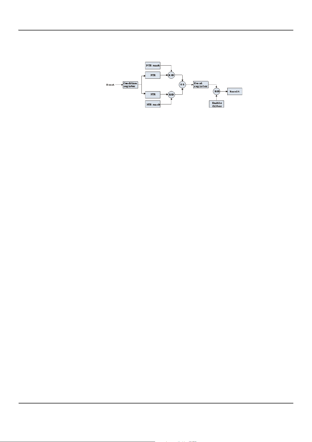
2201R Mobile Tester SCPI Reference Guide
Chapter 2 Remote control of the 2201R Mobile Tester
The figure below gives an example of a group of registers.
A group of registers starts with a Condition register. An internal Event sets the corresponding bit of the Condition
register (to 'set a bit' means a transition from binary 0 to a binary 1). Any Condition register is updated continuously.
This means that a bit is reset as soon as the condition which raised that bit is no longer valid.
Example:
As soon as the 2201R starts to page a mobile under test, a certain bit of a certain condition register is set. When the
2201R stops paging the mobile (because, for example, it responded to the paging requests), this bit is reset. Now there
is no evidence for a paging process in this Condition register.
Therefore, an Event register is included in every group of registers. In the Event register, a bit remains set even when
the condition for it to be set is no longer valid. Any Event register, however, is cleared after a query.
Example:
Continuing our example from above, in the related Event register, the corresponding bit would still be set. A query of
this register would provide evidence that there has been some paging in progress. However, the Event register is not
able to provide any information if the condition is still valid.
Summary 1: condition-type versus event-type registers
• The condition-type registers reflects the current status of the test set and is updated continuously. When you
would like to know if a special condition is currently valid, then read out the related condition-type register with
a query.
• The condition-type register and the event-type register have an identical structure. This means that they are of
the same length and the single indicator bits are at the same positions.
• The event-type registers are the 'memory' of the status system. Once a bit has been set, it remains set until the
event-type register is read out with a query. When you want to trigger (for example) your program with a certain
event, always read out the related event-type register.
• Event-type registers are read-only and self-destructive. They are cleared after any query.
Transition of a bit from the condition-type to the event-type register
How does a bit find its way to the Event register?
This depends on the transition filter and its settings. The transition filter works as follows:
First, there are two branches: the Positive TRansition and the Negative TRansition filter. Both only react on the
corresponding transitions of bits and both contain as many bit positions as the condition register.
PTR carries a binary 1 at a bit position only when the corresponding bit of the condition register is set, while NTR
carries a binary 1 at a bit position only when the corresponding bit of the condition register is reset.
Both the outputs of PTR and NTR are combined with the corresponding mask, using a logical AND operation.
These masks are user-definable (using the STAT:xxxx:xTR commands) and again contain as many bit positions
as the condition register.
Example:
The only chance for bit 4 (that has just been set in the condition register) to reach the Event register is that the PTR
mask carries a binary 1 at bit position 4.
The logical AND between the PTR filter and the PTR mask then delivers a binary 1. This binary 1 passes the logical OR
and thus sets bit 4 of the Event register.
47090/323
Copyright © 2016 Aeroflex Limited. All rights reserved.
26
Page 27

2201R Mobile Tester SCPI Reference Guide
Chapter 2 Remote control of the 2201R Mobile Tester
Summary 2: from the condition-type to the event-type registers
• There are two detectors for every bit of a condition register: the positive transition and the negative transition
branch. Positive transition means a change of a bit from a binary 0 to a binary 1 while a negative transition is a
bit change from a binary 1 to a 0.
• To every branch, there is a filter mask (PTR and NTR mask). This filter mask is user-definable.
• The filter mask and the result of the transition filter are combined using a logical AND operation.
• The results of the AND operation in both branches are combined, using a logical OR operation.
• The results of the OR operation are the contents of the related event-type register.
Moving up: an event reaches the condition register one hierarchical level up
The Event register contains summary bits, corresponding to the bits of the condition register. A summary bit is set
when the initial event passes the transition filter.
The Enable filter is a mask to filter events that are allowed to move one level up. The Enable filter is user-definable
(using the STAT:xxxx:ENABle commands) and again contains as many bit positions as the condition-type
register.
Again, the Enable filter mask is ANDed with the Event register and a nonzero result finally sets the Result bit. This
Result bit may be a summary bit either in a higher-level register, or in the service register.
Summary 3: raising the Result bit
The event-type register is ANDed with the related Enable filter mask.
The Enable filter mask is user-definable.
The result of the logical AND operation between event-type register and related Enable filter is the Result bit.
The result bit sets the corresponding bit of the condition register one level up.
At the top: the service register
The service register contains eight summary bits: three for the status groups available on the 2201R, two for internal
queue handling, two for remote control and one bit for it's own status: the summary status bit.
When an event passes through and sets one of the seven corresponding summary bits of the service register, the
contents of the service register are ANDed with the service register mask. This mask can be set using the *SRE
common command.
When the logical AND operation of the current contents of the service register and the service register mask leads to
a binary 1, then the summary status bit is set as well.
Table of registers
The STATus subsystem uses and/or provides access the following registers:
Service register
This register represents the highest level within the report structure of the 2201R.
The service register contains eight bits. A detailed description of the service register can be found in the appendix
(SCPI Command Reference).
Event status register group
This group of registers collects all general events of the 2201R Mobile Tester (mostly command errors).
Depending of the setting of the event status register mask, bits set in the event status register may be transferred to
bit 5 of the service register.
For further details regarding the event status register, please refer to section ’The event status register’ on page49.
General operation register group
This group of registers is 16 bits wide and reflects the general operation status of the 2201R.
47090/323
Copyright © 2016 Aeroflex Limited. All rights reserved.
27
Page 28

2201R Mobile Tester SCPI Reference Guide
Chapter 2 Remote control of the 2201R Mobile Tester
NOTE
The commands related to the general operation register group and its subordinate
groups of registers all start with :STATus:OPERation:.
Signaling operation register group
This group of registers is 16 bits wide. Its main task is to deal with events related to the signaling status. The signaling
operations depend on the system option and the contents of the signaling operation register group are detailed in
the appendix.
The Result bit of this group of registers is forwarded to bit 8 of the general operation register group.
GSM signaling flags:
Bit Decimal Meaning
0 1 The signaling is in IDLE state
1 2 The signaling is in PAGING state
GPRS signaling flags:
2 4 The signaling is in CALL ACTIVE state
3 8 The signaling is in CLOSED LOOP state
4 16 The signaling is in ASYNC state (Multislot)
532BS calling
6 64 Reserved
7 128 SMS has been received from mobile
8 256 The mobile is alerting
9 512 The mobile is performing a Location Update
10 1024 The mobile sends a paging response (only in loc. upd. barred
mode)
11 2048 Location Update signalling is running
12 4096 SMS signaling is ongoing
13 8192 Not used.
14 16384 Not used.
15 32768 Not used.
Bit Decimal Meaning
0 1 GPRS attached = 1, not attached = 0
1 2 GPRS signaling in progress
2 4 GPRS measurements active
38Not used.
4 16 Not used.
47090/323
Copyright © 2016 Aeroflex Limited. All rights reserved.
28
Page 29

2201R Mobile Tester SCPI Reference Guide
Chapter 2 Remote control of the 2201R Mobile Tester
532Not used.
6 64 Not used.
7 128 Not used.
8 256 Not used.
9 512 Not used.
10 1024 Not used.
11 2048 Not used.
12 4096 Not used.
13 8192 Not used.
14 16384 Not used.
15 32768 Not used.
Measuring operation register group
This group of registers is 16 bits wide. Its main task is to deal with events related to the measurement status.
The Result bit of this group of registers is forwarded to bit 9 of the general operation register group.
Bit Decimal Meaning
0 1 Set while RFTX measurements are in progress.
1 2 Set while RFRX measurements are in progress.
2 4 Set while RFSPectrum measurements are in progress.
38Not used.
4 16 Not used.
532Not used.
6 64 Set while UE Report or MS Info measurements are in progress.
7 128 Not used.
8 256 Not used.
9 512 Not used.
10 1024 Not used.
11 2048 Not used.
12 4096 Not used.
13 8192 Not used.
14 16384 Not used.
15 32768 Not used.
The FORMat subsystem – overview
The FORMat subsystem sets and queries settings concerning the data output in remote mode.
47090/323
Copyright © 2016 Aeroflex Limited. All rights reserved.
29
Page 30

2201R Mobile Tester SCPI Reference Guide
Chapter 2 Remote control of the 2201R Mobile Tester
The base station and mobile station parameter subsystems
These subsystems allow access to the base station (BS) parameters (i.e. the 2201R simulating a base station) and to
the information received from the mobile under test like the measurement report. The commands of these
subsystems are described here.
CONFigure – This subsystem incorporates all changeable BS parameters of all implemented communication systems.
NOTE
The settings made here directly affect all communication system-specific subsystems.
CALL – This subsystem handles call procedures and allows to read out the measurement report generated by the
mobile under test.
The information available is dependent on the current state of a call, i.e. some commands require an established radio
communication link between the 2201R and the mobile under test.
The CONFigure subsystem
This subsystem incorporates all changeable BS parameters of all systems implemented. The key commands are the
following:
CONFigure:CSYStem
CONFigure:<SystemOption>:...
CONFigure:<SystemOption>:BS:...
or
CONFigure:<SystemOption>:NB:...
CONFigure:<SystemOption> :MSTAtion:..
or
.CONFigure:<SystemOption> :UE:...
CONFigure:<SystemOption> :BER:...
CONFigure:<SystemOption> :GROup:...
CONFigure:COUPloss:...
Selects the communications system to work with.
These commands select parameters within a communications
system.
These are the commands to set specific system parameters
like the base station's RF output power level or its identity.
The mobile-specific information is handed over to the 2201R
using these commands. One example is the power level.
These commands set the BER parameters.
With the help of these commands, groups of measurements
may be defined.
These commands provide access to the coupling loss
compensation feature of the 2201R.
The CALL subsystem
This subsystem contains commands
• for call setup and handling procedures and
• to read out the measurement report, generated by the mobile.
47090/323
Copyright © 2016 Aeroflex Limited. All rights reserved.
30
Page 31

2201R Mobile Tester SCPI Reference Guide
Chapter 2 Remote control of the 2201R Mobile Tester
The Measurement subsystems
The 2201R provides the following measurement subsystems:
“The MEASure subsystem” – This subsystem provides the commands for all kinds of measurements: Single-shot as
well as series of measurements, measurements of single parameters as well as of groups of parameters.
“The FETCh subsystem” – To read out the latest measurement result of a specific parameter or a group of parameters.
NOTE
FETCh requires that a measurement is started first, using the MEASure commands.
NOTE
FETCh neither starts nor terminates continuous measurements.
NOTE
During a running test, parameter changes such as a channel or power level change
result in continuous measurements being stopped.
The MEASure subsystem
The MEASure subsystem is probably the most important SCPI command subsystem of the 2201R. This subsystem
includes all commands to acquire measurement results of the mobile under test.
Measurements can be taken as one-shot measurements or as series of measurements:
Type of
measurement
One-shot [:CONTinuous] Actually :CONT starts a measurement that is
Series :ARRay This command element offers the possibility to
Related command
element
Short description
performed continuously. Single measurement
results can be read out using the related :FETCh
commands.
Thus several measurements can be started (where
those measurements are started first that take the
longest time, like e.g. BER).
carry through a specific measurement a certain
number of times. All the single measurement result
values can be read out with just one command.
Using this feature, measurement results returned
can then be used e.g. for statistic data evaluation
on an external computer.
Example:
First a BER measurement command is issued to start a BER measurement (because it takes some time).
Then several RF TX measurements are performed and the measurement results are read out and used for statistic data
evaluation.
After that the result of the BER measurement is read out.
47090/323
Copyright © 2016 Aeroflex Limited. All rights reserved.
31
Page 32

2201R Mobile Tester SCPI Reference Guide
Chapter 2 Remote control of the 2201R Mobile Tester
Important notes:
• A newly issued RF TX MEASure command terminates any RF TX or RF spectrum measurements currently in prog-
ress.
• A newly issued RF SPectrum MEASure command terminates any RF TX or RF spectrum measurements currently
in progress.
• A newly issued RF RX MEASure command terminates any RF RX measurements currently in progress.
• A newly issued AF MEASure command terminates any RF TX, RF RX, RF spectrum or AF measurements currently
in progress.
• Measurements are always started, using the current system parameters and the current state of the 2201R.
• In case the 2201R is in a state that does not allow a specific measurement command to be performed or com-
pleted, an error message is added to the 2201R’s internal error queue. The related flag in “The STATus subsys-
tem” is set too.
In case this is the first error message to appear within the error queue, the error indicator bit of the service regis-
ter (bit 2) is also set.
:MEASure[:CONTinuous]
MEASure commands that are stated with or without the optional :CONTinuous command element make the
2201R perform the related measurement for an unlimited number of times.
The measurement is only terminated if a new MEASure command of the same or related type is issued (see Notes
above).
Syntax
Parameters
Description
:MEASure[:CONTinuous]<{:measProp}>[?]
The one-shot measurements do not require any parameters.
Starts the (continuous) measurement of the specified measurable property.
The CONTinuous command element is optional.
Unless a measurement result is read out (using the FETCh subsystem), no measurement result values are returned.
The measurement result(s) of any measurement are stored internally. Any previously
stored result is overwritten as soon as a new measurement result has been achieved.
The latest result measured may be read out using the FETCh subsystem.
Any FETCh command waits for a measurement result value(s) to be available. In case
there is more than one measurement result value, the single measurement result values are separated by commas (for example, “50.5,3.46”). Should the FETCh command fail to obtain a measurement result value (because for example the current
state of the 2201R does not allow the measurement to be performed or completed),
a timeout occurs and an error message is added to the 2201R’s internal error queue.
The related flag in the STATus subsystem is set too.
In case this is the first error message to appear within the error queue, the error indicator bit of the service register (bit 2) is also set.
The main application of the combination of the MEAS and the FETC subsystems:
Starting a measurement that takes some time to deliver a measurement result back
(e.g. the BER measurement. After the measurement has been started with the MEAS
command, the test set ‘is free’ to perform other tasks. If in this case the query form of
the MEAS command is used, the test set is blocked until a measurement result is
available.
Sometimes, measurement results need to ‘sweep in’. In this case, the first measurement result might be totally misleading. Using the MEAS command allows the measurement result value to stabilize on a meaningful result before the latest result value
is read out using the
FETC subsystem.
47090/323
Copyright © 2016 Aeroflex Limited. All rights reserved.
32
Page 33

2201R Mobile Tester SCPI Reference Guide
Chapter 2 Remote control of the 2201R Mobile Tester
Query
Examples
The query form of any MEASure command starts the (continuous) measurement of
the specified measurable property.
The CONTinuous command element is optional.
After the first measurement has been completed, the measurement result value(s)
are delivered back in a string as outlined above.
Should the query fail to obtain a measurement result value, a timeout occurs and an
error message is added to the 2201’s internal error queue as explained above.
The main application of the query form of a MEAS command is speed. When combined with ‘fast’ measurements (like e.g. the fast power level measurement), the
query form of a MEAS command delivers measurement results as fast as possible.
Note: The measurement started with the query form of the MEAS command continues in the background. Any further measurement result values may be read out, using
the appropriate FETCh command.
:MEASure:GSM:CONTinuous:RFTX:PPEAk and
:MEASure:GSM:RFTX:PPEAk
are identical. Either command starts the measurement of the peak phase error. The
latest result of this measurement (like “5.84”) is stored internally. It is overwritten
as soon as a new measurement result has been achieved.
To read out the current measurement result, use the FETCh subsystem:
:FETCh:GSM:RFTX:PPEAk?
:MEASure:RFTX:ALL
This command starts the continuous measurement of all relevant RFTX parameters.
After this command has been issued, you may continue with e.g. an RF RX MEASure
command.
All 19 single measurement results are stored internally. As soon as a new measurement result has been achieved, the previous value is overwritten.
To read out the measurement results achieved by the :MEAS:RFTX:ALL command, use the :FETCh:GSM:RFTX:ALL? command.
:MEASure:GSM:RFTX:ALL?
As in the example above, the continuous measurement of all relevant RFTX parameters is started. Unlike the example above, this command waits until all
19 measurement results have been achieved and returns all of them in a string, separated by commas. The measurements continue and later results may be read out,
using the FETCh:GSM:RFTX:ALL? command.
How to convert a result string back into numeric variables
The example program below illustrates how the returned string can be converted back into numeric variables in a
program on an external PC controlling the instrument.
PRINT #scpi, “:MEAS:GSM:RFTX:ALL?”
INPUT #scpi, result$
index = 0
result$ = result$ + “,”
DO
‘ Find the position within result$, where the first comma appears
P = INSTR(result$, “,”)
’ Read out the part of result$ in front of the first comma and convert it into
a numeric value
result(index) = VAL(LEFT$(result$, P – 1))
’ Cut off the value just read from result$
result$ = MID$(result$, P +1))
index = index + 1
47090/323
Copyright © 2016 Aeroflex Limited. All rights reserved.
33
Page 34

2201R Mobile Tester SCPI Reference Guide
Chapter 2 Remote control of the 2201R Mobile Tester
LOOP UNTIL result$=””
MEASure:ARRay
The :ARRay command element makes the 2201R perform any measurement property a user-definable number of
times. All measurement result values obtained during the process are stored in an internal array and can be read out
using the related commands of the FETCh subsystem or are returned in case the measurement process has been
started using the query format of the command.
After the specified number of measurements has been performed, the measurements are stopped and no further
measurement result values are stored internally. Therefore, any attempt to read out data again (unless any
measurement has been started before) results in a timeout and thus in an error message.
This is one of the main differences between the [:CONTinuous] and the :ARRay command element.
Note: Any measurement is terminated if a new MEASure command of the same or related type is issued (see Notes
in section ’The MEASure subsystem’ on page31 for details).
Syntax
Parameters
Description
Query
Examples
MEASure:ARRay<{:measProp}>[?] <numMeas>
numMeas is the number of measurements to be performed.
Tak es a numMeas number of measurements of the specified type measProp.
The results of the single measurements are stored in an internal array.
The measurement results array can be read out using the related command of the
FETCh subsystem (see examples below for reference).
After an array has been read out using the related FETCh command, the internal
array is cleared. Any subsequent FETCh command trying to read out the same measurement result array is not able to read any measurement results and thus results in
a timeout. In this case, an error message is added to the 2201’s internal error queue
(for further details, refer to section ’:MEASure[:CONTinuous]’ on page32).
The query form of any MEAS:ARR command starts the related measurement the
specified number of times. After the number of measurements specified has been
performed, the measurements are stopped.
The query then returns a string containing all the measurement results. The single
result values are separated by commas.
Any subsequent FETCh command trying to read out the same measurement result
array is not able to read any measurement results and thus results in a timeout. In this
case, an error message is added to the 2201’s internal error queue (for further details,
refer to section ’:MEASure[:CONTinuous]’ on page32).
:MEASure:GSM:ARRay:RFTX:PPEAk 10
This command makes the 2201R perform 10 independent measurements of the
maximum phase error in GSM.
After those 10 results have been achieved, the measurement is stopped.
The 10 result values are stored in an internal array.
To read out the measurement result array, use the FETCh subsystem:
:FETCh:GSM:RFTX:PPEAK?
returns the 10 values in one string (like “5.42,5.44,5.80,...5.72,5.64”)
Any subsequent :FETCh:GSM:RFTX:PPEAK? command results in a timeout.
MEASure:GSM:ARRay:RFTX:ALL? 2
This command takes all relevant RFTX measurements twice. The measurements are
stopped as soon as the 2 x 19 result values are available.
The 38 result values are returned as a string; the single values are separated by commas.
Any subsequent :FETCh:GSM:RFTX:PPEAK? command results in a timeout.
47090/323
Copyright © 2016 Aeroflex Limited. All rights reserved.
34
Page 35

2201R Mobile Tester SCPI Reference Guide
Chapter 2 Remote control of the 2201R Mobile Tester
How to convert a result string back into numeric variables
The example program below illustrates how the returned string can be converted back into numeric variables in a
program running on an external PC to control the instrument.
PRINT #scpi, “:MEAS:GSM:ARR:RFTX:ALL? 2”
INPUT #scpi, result$
index = 0
result$ = result$ + “,”
DO
‘ Find the position within result$, where the first comma appears
P = INSTR(result$, “,”)
’ Read out the part of result$ in front of the first comma and convert it into
a numeric value
result(index) = VAL(LEFT$(result$, P – 1))
’ Cut off the value just read from result$
result$ = MID$(result$, P +1))
index = index + 1
LOOP UNTIL result$=””
:MEAS[:CONT]:BLOCkdata
The BLOCkdata command element of this subsystem is used to read out all the single measurement results
necessary to generate the result graphics.
:MEASure:...:GROup
As mentioned before (see Notes in section ’The MEASure subsystem’ on page31), a new measurement always
terminates a preceding one of the same or related type.
Therefore, the GROup command element has been implemented in the SCPI command set of the 2201R. This
command element allows to specify a user-definable list of measurements than can then be started with one
command. The measurement results can be read out using the query form of this command – or with the related
command of the FETCh subsystem.
NOTE
In this respect, :MEAS:RFTX:ALL can be regarded as a predefined ‘group’,
containing all important RFTX measurements.
47090/323
Copyright © 2016 Aeroflex Limited. All rights reserved.
35
Page 36

2201R Mobile Tester SCPI Reference Guide
Chapter 2 Remote control of the 2201R Mobile Tester
Syntax
:CONFigure:MEASure:GROup[:RFTX] <{RFTXprop}>
MEASure[:CONTinuous]:RFTX:GROup or
MEASure:ARRay:RFTX:GROup
Parameters
<{RFTXprop}> is one or more of the single RFTX measurements
PPEAk,PRMS,FREQuency,LENGth,UTIMe,POWer,TEMPlate,CORNer,FLATness
Description
Starting a ‘group’ measurement takes all measurements specified just with one single
command.
After the group command has been completed, all ‘group’ measurement results are
available at the same time and can be read out using either the query form of the
command or the related commands of the FETCh subsystem.
Example
:CONF:GSM:MEAS:GRO:RFTX PPEAK,FREQency,POWer,LENGth
:MEAS:RFTX:GRO
This sequence of commands first defines a group of RFTX measurements and then
issues a group command. As soon as all the measurements specified in the group
command have been completed, the measurement result values can be read out
using the :FETCh:GSM:RFTX:GRO? command.
The FETCh subsystem
The FETCh subsystem enables you to read out the currently valid measurement result value(s) of a measurement.
Important notes
• Before a measurement value may be read out with commands of the FETCh subsystem, a MEASure command
has to be issued first.
• After a continuous measurement has been started, the latest measurement result value can be obtained using
the related :FETCh command.
• In case an array measurement has been started, the related :FETCh command returns the entire measurement
result array.
• If there are no measurement results to be read out by a FETCh command for any reason, a timeout occurs. The
wait time until a timeout occurs is dependent on the type of measurement to be performed (see below).
• If the preceding MEASure command and the FETCh command do not match, a timeout occurs.
• When you use the query form of any MEASure command, all measurement results obtained are handed back
and the internal result register is cleared afterwards. Consequently, a subsequent FETCh command leads to a
timeout (as above).
• The following timeouts have been implemented:
– 5 s for all RFTX measurements
– 30 s for all RFRX measurements
– 10 s for all RFSPectrum measurements
– 10 s for all AF measurements
There are two versions of a FETCh command:
•The :FETCh:LAST? command reads out the latest result of the last MEASurement command issued — what-
ever command that was.
Using this command, please keep in mind that your control program then has to take care of the number and for-
mat of the measurement result values returned.
•The :FETCH:{measProp}; commands read out the latest result of the measurement specified with {mea-
sProp}.
47090/323
Copyright © 2016 Aeroflex Limited. All rights reserved.
36
Page 37

2201R Mobile Tester SCPI Reference Guide
Chapter 2 Remote control of the 2201R Mobile Tester
FETCh:LAST
The :FETCh:LAST? command reads out the latest result of the last MEASurement command issued - whatever
command that was.
Using this command, please keep in mind that your control program then has to take care of the number and format
of the measurement result values returned.
To convert a result string back into single measurement result values, please refer to section ’How to convert a result
string back into numeric variables’ on page33.
FETCh:BLOCkdata:...?
The commands with the :BLOCkdata command element are used to read out all the single measurement results
necessary to generate the result graphics.
FETCh<{:measProp}>
The :FETCH<{:measProp}> commands read out the latest result of the measurement specified with
measProp.
47090/323
Copyright © 2016 Aeroflex Limited. All rights reserved.
37
Page 38

SCPI command errors
This subsection contains a table of SCPI command errors.
NOTE
If a query for an error code returns “0” then no error did occur.
Error Code Meaning
100 Command error.
101 Invalid character.
102 Syntax error.
103 Invalid separator.
2201R Mobile Tester SCPI Reference Guide
Chapter 2 Remote control of the 2201R Mobile Tester
104 Data type error.
108 Parameter not allowed.
109 Parameter missing.
111 Header separator error.
112 Program mnemonic too long.
113 Undefined header.
114 Header suffix out of range.
121 Invalid character within a number.
123 Exponent too large.
128 Numeric data not allowed in this context.
131 Invalid suffix.
134 Suffix too long.
138 No suffix allowed in this context.
141 Invalid character data.
144 Character data too long.
145 ENUM data too long.
158 No string allowed in this context.
160 Block data error.
168 No block data allowed in this context.
200 General execution error.
201 Execfunc error.
202 Query function error.
221 Different parameter settings lead to a conflict.
222 Data out of range.
47090/323
Copyright © 2016 Aeroflex Limited. All rights reserved.
38
Page 39

2201R Mobile Tester SCPI Reference Guide
Chapter 2 Remote control of the 2201R Mobile Tester
250 Mass storage error.
256 File name not found.
272 Macro execution error.
280 Program error.
310 System error.
350 Queue overflow.
47090/323
Copyright © 2016 Aeroflex Limited. All rights reserved.
39
Page 40

Chapter 3
Introduction to the SCPI command reference
This chapter includes important notes on the SCPI commands and how they are described in the subsequent
chapters. Topics discussed in this chapter are as follows:
• ’SCPI command reference structure’ on page41
• ’Command response on USB, RS-232 and TCP/IP’ on page41
• ’Bluetooth commands’ on page41
• ’Signaling operation register group’ on page41
47090/323
Copyright © 2016 Aeroflex Limited. All rights reserved.
40
Page 41

2201R Mobile Tester SCPI Reference Guide
Chapter 3 Introduction to the SCPI command reference
SCPI command reference structure
The following chapters contain lists of SCPI commands and queries. Each command is described with its valid input
and output formats. There is a chapter for each subsystem.
Command response on USB, RS-232 and TCP/IP
Every command sent to the 2201R is answered by the terminator string as set with the respective command:
• TCP/IP: :SYSTem:COMMunicate:TCP:TERMinator <CRLF|LF|CR>
• RS232: :SYSTem:COMMunicate:SERA:TERMinator <CRLF|LF|CR>
• USB: :SYST em:COMMunicate:SERB:TERMinator <CRLF|LF|CR>
Bluetooth commands
The SCPI commands for the 4489 Bluetooth Connectivity Test Package can be found in the Bluetooth Connectivity
Test Products User Guide.
Signaling operation register group
This group of registers is 16 bits wide. Its main task is to deal with events related to the signaling status. The signaling
operations depend on the system option and can be found in the :STATus:OPERation:SIGNalling group of commands
(see the respective EVENt command for the signaling system at hand).
The Result bit of this group of registers is forwarded to bit 8 of the general operation register group.
47090/323
Copyright © 2016 Aeroflex Limited. All rights reserved.
41
Page 42

Chapter 4
Common commands
This chapter contains an explanation of the common SCPI commands. The list is structured as follows:
• ’Introduction’ on page43
• ’General common commands’ on page43
• ’The event status register’ on page49
• ’The service register’ on page50
47090/323
Copyright © 2016 Aeroflex Limited. All rights reserved.
42
Page 43

2201R Mobile Tester SCPI Reference Guide
Introduction
The common commands are understood by all SCPI and IEEE 488.2 instruments. Their purpose is to perform general
tasks and to r ead or work wit h the reg isters common to all SC PI instr ument s. The fo llowing common commands have
been implemented.
General common commands
:REBoot
Syntax
:REBoot
Parameters
There are no parameters.
Description
Chapter 4 Common commands
Reboots the operating system. The current settings are not affected by this command.
Query
There is no query form of this command available.
Example
:REBoot
*CAL?
Syntax
*CAL?
Parameters
There are no parameters.
Description
The command form is not available.
Query
Returns date of last calibration by Cobham in the form yyyy,mm,dd
Example
*CAL?
Returns "2014,12,31"
47090/323
Copyright © 2016 Aeroflex Limited. All rights reserved.
43
Page 44

2201R Mobile Tester SCPI Reference Guide
Chapter 4 Common commands
*CLS
Syntax
*CLS
Parameters
There are no parameters.
Description
Resets the entire status reporting system:
The service register is cleared (all bits are set to 0).
The event status register is cleared (all bits are set to 0).
The error message queue is emptied.
All event-type registers are cleared.
Query
There is no query form of this command available.
Example
*CLS
*ESE
Syntax
*ESE <int1>
Parameters
int1 is an integer. The valid range is from 0 to 255 (8 bits).
Description
Sets the enable filter (mask) of the event status register.
int1 is the decimal representation of the binary mask.
The mask and the current contents of the event status register are ANDed. If the result is not zero, then bit 5 of the
service register is set.
Query
The query form reads out the enable filter (mask) currently set and returns its binary representation in a string.
Example
*ESE 128
As soon as power has been switched on, bit 7 (Power on) is set. ANDed with the mask 128, a binary 1 occurs and thus
bit 5 of the service register is set.
47090/323
Copyright © 2016 Aeroflex Limited. All rights reserved.
44
Page 45

2201R Mobile Tester SCPI Reference Guide
Chapter 4 Common commands
*ESR
Syntax
*ESR
Parameters
There are no parameters.
Description
There is only a query form of this command available.
Query
Returns the decimal representation of the current contents of the event status register in a string.
Note: This register is self-destructive: its contents are cleared after reading.
Example
After power-on, the *ESR?query returns "128". This means that bit 7 is set and all the other bits of the event status
register are 0.
The command clears the event status register and a subsequent *ESR? query returns "0".
*IDN?
Syntax
*IDN?
Parameters
There are no parameters.
Description
There is only a query form of this command available.
Query
Returns a string containing the following information:
- manufacturer name
- name of the device
- serial number
- software revision number
All parameters are separated by commas.
Note: In times of company mergers and acquisitions, it is a good idea to check the name of the device, not the
manufacturer name which may change between software updates. This does not preclude any name changes at
Cobham but rather applies to instrumentation in general.
Example
*IDN?
Returns "Aeroflex, 2201, 0003237, 1.30.001"
Copyright © 2016 Aeroflex Limited. All rights reserved.
47090/323
45
Page 46

2201R Mobile Tester SCPI Reference Guide
Chapter 4 Common commands
*OPT
Syntax
*OPT
Parameters
There are no parameters.
Description
The command form is not available.
Query
Returns the options that are included in this 2201R. A string with the installed options separated by commas is
returned.
Example
*OPT?
Returns in this example
"2201,MANUAL,REMOTE,AUTOTEST,GSM_CALL_MODE,GPRS_CALL_MODE,EDGE_GSMR_CALL_MODE"
*RST
Syntax
*RST
Parameters
There are no parameters.
Description
Resets the entire test set. All parameters, limits etc. are set to the internally predefined default values.
Query
There is no query form of this command available.
Example
*RST
47090/323
Copyright © 2016 Aeroflex Limited. All rights reserved.
46
Page 47

2201R Mobile Tester SCPI Reference Guide
Chapter 4 Common commands
*STB
Syntax
*STB
Parameters
There are no parameters.
Description
There is only a query form of this command available.
Query
Returns the decimal representation of the current contents of the service register in a string.
Note: This register is self-destructive: its contents are cleared after reading.
Example
A *STB? query returns "68". The return value of 68 (= 64 + 4) means that an error occurred (4).
*OPC?
Syntax
*OPC?
Parameters
There are no parameters.
Description
There is only a query form of this command available.
Query
Waits until previous command is completed. In addition, query returns the Operation Complete flag which is 1 in the
successful case.
Example
*OPC?
Returns "1"
47090/323
Copyright © 2016 Aeroflex Limited. All rights reserved.
47
Page 48

2201R Mobile Tester SCPI Reference Guide
Chapter 4 Common commands
*SRE
Syntax
*SRE <int1>
Parameters
int1 is an integer. The valid range is from 0 to 255 (8 bits).
Description
Sets the enable filter (mask) of the service register.
int1 is the decimal representation of the binary mask.
The mask and the current contents of the seventh status register are ANDed.
Query
The query form reads out the mask currently set and returns its binary representation in a string.
Example
*SRE 68
As soon as an error occurs, bits 2 and 6 of the service register are set. ANDed with the mask 68, a binary 1 is the result.
47090/323
Copyright © 2016 Aeroflex Limited. All rights reserved.
48
Page 49

The event status register
The event status register contains eight bits. The meaning of these bits is outlined in the table below.
The commands working on the event status register are described below the table.
Bit Decimal Meaning
7 128 Power on – this bit is always set.
664Not used.
5 32 Command error – this bit indicates that one of the SCPI
4 16 Execution error – is set after a SCPI execution error did occur.
3 8 Device-dependent error – this bit indicates that a device-specific
2 4 Query error – is set after a SCPI query error occurred.
2201R Mobile Tester SCPI Reference Guide
Chapter 4 Common commands
command errors occurred.
SCPI error did occur.
1 2 Request control – this bit is reserved for future use.
0 1 Operation complete flag – is set as soon as the execution of a
command has been completed.
47090/323
Copyright © 2016 Aeroflex Limited. All rights reserved.
49
Page 50

The service register
The service register represents the highest level within the report structure of the 2201R.
The service register contains eight bits.
If any one of the bits 0...5 or 7 is set, the summary status bit (bit 6) of the service register is set as well.
NOTE
The service register is self-destructive. This means that its contents are cleared after
reading.
Bit Decimal Meaning
2201R Mobile Tester SCPI Reference Guide
Chapter 4 Common commands
7 128 OPERational status summary. When this bit is set, an event
within the General Operation register group (e.g. the 2201R is
waiting for a trigger) passed all filters.
6 64 Summary status bit. This bit is always set as soon as any other
bit of the service register has been set.
Note: The related command is *SRE (see below for details).
5 32 Event status summary. When this bit is set, an event within the
Event Status register group (e.g. an error occurred) passed all
filters.
4 16 Message available. This bit is set to 1 as soon as a query has
been completed and measurement result(s) are available.
3 8 Not used.
2 4 Error queue status. When this bit is set, the error queue contains
error messages. Up to 10 error messages can be logged in the
error queue. The error queue can be read out, using the
:SYSTem:ERRor? command.
1 2 Remote command completed. This bit is set to 1 after a remote
(SCPI) command has been completed.
Note: However, when the 2201R receives a SCPI command, it
blocks the remote control interface until the command has been
completed.
0 1 Message queue status.
This bit is set to 1 as soon as a message is available in the
2201R's internal message queue. Up to 10 messages can be
logged in the message queue. To write to or to read from the
message queue, use the :SYSTem:MESSage command.
47090/323
Copyright © 2016 Aeroflex Limited. All rights reserved.
50
Page 51

Chapter 5
System commands
This chapter contains an explanation of the SCPI commands from the System subsystem. The chapter is structured
as follows:
• ’Introduction’ on page52
• ’System subsystem’ on page52
47090/323
Copyright © 2016 Aeroflex Limited. All rights reserved.
51
Page 52

Introduction
System parameters, such as the number of unread error messages, the test set's interface parameters etc. may be read
out or set using the commands of this subsystem.
System subsystem
:SYSTem:ERRor[:NEXT]?
Syntax
:SYSTem:ERRor[:NEXT]?
Parameters
There are no parameters.
Description
There is solely a query form of this command available.
2201R Mobile Tester SCPI Reference Guide
Chapter 5 System commands
Query
Returns the oldest unread error message from the internal error queue of the 2201R. The queue entry returned is a
string containing the error no. and additional text. The maximum length of the string is 255 characters.
Note: An overview of all SCPI error messages can be found in section SCPI command errors.
Example
:SYSTem:ERRor:NEXT?
String returned: 113,"Undefined header;(0)^SCPIParseCommand: SYSTEM:WRONG:CMD "
:SYSTem:ERRor:COUNt?
Syntax
:SYSTem:ERRor:COUNt?
Parameters
There are no parameters.
Description
There is solely a query form of this command available.
Query
Returns the number of unread error messages in the internal error queue of the 2201R. The string returned contains
one integer. The maximum number of errors stored internally is 10.
Example
:SYSTem:ERRor:COUNt?
String returned: "0"
This means that there are no unread error messages in the error queue.
47090/323
Copyright © 2016 Aeroflex Limited. All rights reserved.
52
Page 53

2201R Mobile Tester SCPI Reference Guide
Chapter 5 System commands
:SYSTem:ERRor:CODE[:NEXT]?
Syntax
:SYSTem:ERRor:CODE[:NEXT]?
Parameters
There are no parameters.
Description
There is solely a query form of this command available.
Query
Returns the code of the oldest unread error message in the internal error queue of the 2201R. The string returned
contains one integer (and no text).
Note: An overview of all SCPI error messages can be found in section SCPI command errors.
Example
:SYSTem:ERRor:CODE?
String returned: -113
This means that there is an Undefined header.
:SYSTem:ERRor:CODE:ALL?
Syntax
:SYSTem:ERRor:CODE:ALL?
Parameters
There are no parameters.
Description
There is solely a query form of this command available.
Query
Returns the error codes of all unread error messages in the internal error queue of the 2201R. The string returned
contains a maximum of 10 integers, separated by commas.
Note: An overview of all SCPI error messages can be found in section SCPI command errors.
Example
:SYSTem:ERRor:CODE:ALL?
String returned: "-371,-113"
This means that there were two unread error messages in the error queue.
47090/323
Copyright © 2016 Aeroflex Limited. All rights reserved.
53
Page 54

2201R Mobile Tester SCPI Reference Guide
Chapter 5 System commands
:SYSTem:Message
Syntax
:SYSTem:Message <string1>
Parameters
string1 is a string (text) parameter. The maximum length of string1 is 255 characters.
Description
Writes the message specified with the string1 parameter to the internal system message queue of the instrument.
Query
Reads and returns the oldest unread message in the internal message queue. The string returned contains a maximum
of 255 characters.
Example
:SYSTem:MESSage "23.17,Procedure A5"
:SYST:MESS?
String returned: "23.17,Procedure A5"
In this example, a RAPID! program performs some internal calculations and then writes the result to the system
message queue. This result is then read by the external controller.
:SYSTem:COMMunicate:LOCal
Syntax
:SYSTem:COMMunicate:LOCal
Parameters
There are no parameters.
Description
Sets up the 2201R to allow manual operation on the front panel during SCPI operation.
Note: This command may be used e.g. to allow interactive alignment procedures in a production or quality assurance
flow.
Query
There is no query form of this command available.
Example
:SYSTem:COMM:LOC
47090/323
Copyright © 2016 Aeroflex Limited. All rights reserved.
54
Page 55

2201R Mobile Tester SCPI Reference Guide
Chapter 5 System commands
:SYSTem:COMMunicate:TCPip:ADDRess
Syntax
:SYSTem:COMMunicate:TCPip:ADDRess <string>
Parameters
string is a string only containing the IP address for the 2201R.
Description
This command sets the IP address of the 2201R. See section I/O Configuration for more details.
Query
Reads and returns the current setting of the IP address as explained above.
Example
SYST:COMM:TCP:ADDR "192.16.16.114" sets the IP address to a defined value.
:SYSTem:COMMunicate:TCPip:NETMask
Syntax
:SYSTem:COMMunicate:TCPip:NETMask <string>
Parameters
string is a string only containing the net mask for the 2201R.
Description
This command sets the net mask of the 2201R. See section I/O Configuration for more details.
Query
Reads and returns the current setting of the net mask as explained above.
Example
SYST:COMM:TCP:NETM "255.255.255.0" sets the net mask to a defined value.
47090/323
Copyright © 2016 Aeroflex Limited. All rights reserved.
55
Page 56

2201R Mobile Tester SCPI Reference Guide
Chapter 5 System commands
:SYSTem:COMMunicate:TCPip:GATeway
Syntax
:SYSTem:COMMunicate:TCPip:GATeway <string>
Parameters
string is a string only containing the default gateway address for the 2201R.
Description
This command sets the default gateway address of the 2201R. See section I/O Configuration for more details.
Query
Reads and returns the current setting of the gateway address as explained above.
Example
SYST:COMM:TCP:GAT "192.16.16.1" sets the gateway address to a defined value.
:SYSTem:COMMunicate:TCPip:PORT
Syntax
:SYSTem:COMMunicate:TCPip:PORT <int>
Parameters
int defines the TCP/IP port address of the 2201R. The address must be in the range from 49152 to 65535.
Description
This command sets the port address on which the 2201R can be controlled via LAN. See section I/O Configuration
for more details.
Query
Reads and returns the current setting of the port used by TCPIP as explained above.
Example
SYST:COMM:TCP:PORT 49200 sets the TCP/IP port address to its default.
47090/323
Copyright © 2016 Aeroflex Limited. All rights reserved.
56
Page 57

2201R Mobile Tester SCPI Reference Guide
Chapter 5 System commands
:SYSTem:COMMunicate:TCPip:TERMinator
Syntax
:SYSTem:COMMunicate:TCPip:TERMinator <PredefExp>
Parameters
PredefExp can take on one of the following values: LF or CR or CRLF. The default is LF.
Description
The command defines the delimiter for SCPI control strings for the TCP/IP interface. See section I/O Configuration
for more details.
Query
Reads and returns the current setting of the terminator used by TCPIP as explained above.
Example
SYST:COMM:TCP:TERM CRLF sets the line terminator for SCPI commands via LAN to CR (Carriage Return) followed
by LF (Line Feed).
:SYSTem:COMMunicate:TCPip:MOUNt
Syntax
:SYSTem:COMMunicate:TCPip:MOUNt <string1> <string2>
Parameters
string1 defines the network address which is mounted as a device for remote control. The maximum allowable length
of the string is 255 characters.
string2 is the symbolic device address used in SCPI programming. The maximum allowable length of string2 is 25
characters. The default is "server".
Description
This command mounts a server disk as a 2201R device that can be used to load or save data to/from. See section I/O
Configuration for more details.
Query
Reads and returns the last settings for the mount path and the corresponding local name as explained above.
Example
:SYST:COMM:TCP:MOUNt "unixpc/disk2/results","resdir"
47090/323
Copyright © 2016 Aeroflex Limited. All rights reserved.
57
Page 58

2201R Mobile Tester SCPI Reference Guide
Chapter 5 System commands
:SYSTem:COMMunicate:TCPip:DHCP
Syntax
:SYSTem:COMMunicate:TCPip:DHCP <PredefExp>
Parameters
PredefExp can take on one of the following values: ON or OFF. The default is OFF.
Description
The command turns DHCP on or off. See section I/O Configuration for more details.
Query
Reads and returns the current setting of DHCP operation.
Example
:SYST:COMM:TCP:DHCP ON sets the software to use DHCP.
:SYSTem:COMMunicate:TCPip:MACaddr?
Syntax
:SYSTem:COMMunicate:TCPip:MACaddr?
Parameters
There are no parameters.
Description
There is solely a query form of this command available.
Query
This query gets the MAC address from the 2201R.
Example
SYST:COMM:TCP:MAC? "0050C221997D"
47090/323
Copyright © 2016 Aeroflex Limited. All rights reserved.
58
Page 59

2201R Mobile Tester SCPI Reference Guide
Chapter 5 System commands
:SYSTem:COMMunicate:SERA:REMote
Syntax
:SYSTem:COMMunicate:SERA:REMote <PredefExpr>
Parameters
PredefExpr can take on either of the following expressions: ON|OFF. Default is ON.
Description
Enables or disables remote control of the 2201R via the serial interface port COM 1.
Note: The remote control capability at COM 1 should be disabled prior to controlling external equipment (e.g. the
Bluetooth Connectivity Test products) through this interface.
Query
Returns the current setting.
Example
:SYST:COMM:SERA:REM OFF
:SYST:COMM:SERA:REM?
Returns the following string: "OFF"
:SYSTem:COMMunicate:SERA:TERMinator
Syntax
:SYSTem:COMMunicate:SERA:TERMinator <PredefExpr>
Parameters
PredefExpr can take on either of the following expressions: LF|CR|CRLF.
Description
The command defines the delimiter for SCPI control strings for the RS-232 interface.
Query
Reads and returns the current setting of the terminator used on the RS-232 interface.
Example
:SYST:COMM:SERA:TERM LF
:SYST:COMM:SERA:TERM?
Returns the following string: "LF"
47090/323
Copyright © 2016 Aeroflex Limited. All rights reserved.
59
Page 60

2201R Mobile Tester SCPI Reference Guide
Chapter 5 System commands
:SYSTem:COMMunicate:SERB:TERMinator
Syntax
:SYSTem:COMMunicate:SERB:TERMinator <PredefExpr>
Parameters
PredefExpr can take on either of the following expressions: LF|CR|CRLF.
Description
The command defines the delimiter for SCPI control strings on the USB interface.
Query
Reads and returns the current setting of the terminator used on the USB interface.
Example
:SYST:COMM:SERB:TERM LF
:SYST:COMM:SERB:TERM?
Returns the following string: "LF"
:SYSTem:DATE
Syntax
:SYSTem:DATE <int1>,<int2>,<int3>
Parameters
intx are three integers.
The minimum value for int1 is 1998, the maximum is 2100. The default value is 1998.
The minimum value for int2 is 1, the maximum is 12. The default value is 1.
The minimum value for int3 is 1, the maximum is 31. The default value is 1.
Description
Sets the system date. This command uses the following format: yyyymmdd where
yyyy stands for the four digits of the year (int1),
mm gives the two digits of the current month (int2) and,
dd represents the day of the current month (int3).
Query
Reads and returns the current system date in a string, using the format explained above.
Example
:SYST:DATE 2014,7,6
Sets the system date to the 6th of July, 2014.
47090/323
Copyright © 2016 Aeroflex Limited. All rights reserved.
60
Page 61

2201R Mobile Tester SCPI Reference Guide
Chapter 5 System commands
:SYSTem:TIME
Syntax
:SYSTem:TIME <int1>,<int2>,<int3>
Parameters
intx are three integers.
The minimum value for int1 is 0, the maximum is 23. The default value is 0.
The minimum value for int2 is 0, the maximum is 59. The default value is 0.
The minimum value for int3 is 0, the maximum is 59. The default value is 0.
Description
Sets the system time. This command uses the following format: hhmmss where
hh stands for the two digits of the current hour, using a 24 hour time format (int1),
mm gives the two digits of the current minute (int2) and,
ss represents the seconds of the system time (int3).
Query
Reads and returns the current system time in a string, using the format explained above.
Example
:SYST:TIME?
String returned: "12,56,05".
:SYSTem:SHUTdown
Syntax
:SYSTem:SHUTdown
Parameters
There are no parameters.
Description
Immediate shutdown of the 2201R.
Query
The query form of this command is not available.
Example
SYST:SHUT
Immediate shutdown of the 2201R.
47090/323
Copyright © 2016 Aeroflex Limited. All rights reserved.
61
Page 62

Chapter 6
Status commands
This chapter contains an explanation of the Status subsystem SCPI commands. The list is structured as follows:
• ’Introduction’ on page63
• ’STATus commands’ on page63
47090/323
Copyright © 2016 Aeroflex Limited. All rights reserved.
62
Page 63

Introduction
The STATus subsystem offers commands to read out and deal with the general operation register group and its
subordinate groups of registers.
Please see section ’The STATus subsystem’ on page25 for more details, including the meaning of the status register
bits.
NOTE
The commands to deal with the event status register group and the service register are
part of the SCPI command errors.
STATus commands
:STATus:PRESet
Syntax
2201R Mobile Tester SCPI Reference Guide
Chapter 6 Status commands
:STATus:PRESet
Parameters
There are no parameters.
Description
This command sets all user-definable settings of the status subsystem to their factory default values. The default
values for the single commands are explained below.
Query
There is no query form of this command available.
Example
:STATus:PRESet
Resets all parameters of the status subsystem to their default values as listed below.
47090/323
Copyright © 2016 Aeroflex Limited. All rights reserved.
63
Page 64

2201R Mobile Tester SCPI Reference Guide
Chapter 6 Status commands
:STATus:OPERation[:EVENt]?
Syntax
:STATus:OPERation[:EVENt]?
Parameters
There are no parameters.
Description
Reads out the current contents of the General Operation Event Register.
Note: Event-type registers are read-only and self-destructive. They are cleared after any query.
Query
There is only a query form of this command available. The query returns a string containing one integer.
The value returned represents all general operation events that have occurred since the last query of this register. As
with any event-type register, the single bits remain set even when the reason for the bits to be set is no longer valid.
Please note that this is the main difference between event-type and condition-type registers. Condition-type
registers reflect the current state of the 2201R. Consequently, condition-type registers are updated continuously.
Note: In case a certain event is trapped in a loop within a program, always query the event-type register.
Example
:STATus:OPERation:EVENt?
Value returned: "32".
This means that bit 5 (the "waiting for a trigger" bit) has been set. This indicates that a "waiting for a trigger" event did
occur. If you want to know whether the 2201R is still waiting for the trigger to occur, read out the related
condition-type register (see command explained below).
:STATus:OPERation:CONDition?
Syntax
:STATus:OPERation:CONDition?
Parameters
There are no parameters.
Description
This command reads out the current contents of the General Operation Condition Register. This register reflects the
current operational state of the 2201R and is updated continuously.
Note: This register is nondestructive. This means that it keeps its contents after any query.
Query
There is only a query form of this command available. The query returns a string containing one integer. The integer
expresses all bits currently set in the 16-bit general operation condition register.
Note: Bit 15 (the MSB) of this register is not used. Therefore, the maximum value returned is "32767".
Example
:STATus:OPERation:CONDition?
Value returned: "512".
This means that bit 9 (the MEASure summary bit) has been set, indicating that some measurement is currently in
progress. Bit 9 is reset as soon as the measurement has been completed.
47090/323
Copyright © 2016 Aeroflex Limited. All rights reserved.
64
Page 65

2201R Mobile Tester SCPI Reference Guide
Chapter 6 Status commands
:STATus:OPERation:ENABLe
Syntax
:STATus:OPERation:ENABLe <int1>
Parameters
int1 is an integer. The minimum value for int1 is 0, the maximum value is 32767. The default value is 0.
Description
This command sets the Enable filter of the General operation register group. This mask is ANDed with the general
operation event register and thus decides what kind of events are forwarded to bit 7 of the service register.
Note: The service register is often also referred to as the status byte register or status byte.
Query
There is no query form of this command available.
Example
:STATus:OPERation:ENABle 129
This means that any setting of bits 1 (calibrating) or 7 (correcting) of the general operation event register raises bit
7 of the service register.
:STATus:OPERation:PTRansition
Syntax
:STATus:OPERation:PTRansition <int1>
Parameters
int1 is an integer. The minimum value for int1 is 0, the maximum value is 32767. The default value is 32767.
Description
Sets the PTR mask of the General operation register group. This mask is ANDed with the up to 15 bits of the PTR
transition filter of the general operation condition register to allow a positive transition of any bit (i.e. a transition
from logic 0'to'1')toreachthegeneraloperationeventregister.'
Notes
- The default of this mask is 32767 — that means that the mask allows any positive transition of the lower 15 bits of
the condition-type register to reach the event-type register.
- Bit 16 of the general operation condition register is not used.
Query
There is no query form of this command available.
Example
:STATus:OPERation:PTRansition 0
This means that none of the positive transitions of the condition-type register are forwarded to the event-type
register.
47090/323
Copyright © 2016 Aeroflex Limited. All rights reserved.
65
Page 66

2201R Mobile Tester SCPI Reference Guide
Chapter 6 Status commands
:STATus:OPERation:NTRansition
Syntax
:STATus:OPERation:NTRansition <int1>
Parameters
int1 is an integer. The minimum value for int1 is 0, the maximum value is 32767. The default value is 0.
Description
Sets the NTR mask of the General operation register group. This mask is ANDed with the up to 15 bits of the NTR
transition filter of the general operation condition register to allow a reset (negative transition) of any bit (i.e. a
transition from logic "1" to "0") to reach the general operation event register.
Notes
- The default of this mask is 0 — that means that the mask does not allow any negative transition of the lower 15
bits of the condition-type register to reach the event-type register.
- Bit 16 of the general operation condition register is not used.
Query
There is no query form of this command available.
Example
:STATus:OPERation:NTRansition 32767
This means that all of the negative transitions of the condition-type register are forwarded to the event-type register.
47090/323
Copyright © 2016 Aeroflex Limited. All rights reserved.
66
Page 67

2201R Mobile Tester SCPI Reference Guide
Chapter 6 Status commands
:STATus:OPERation:SIGNalling:GSM[:EVENt]?
Syntax
:STATus:OPERation:SIGNalling:GSM[:EVENt]?
Parameters
There are no parameters.
Description
Reads out the current contents of the signaling operation event register.
Note: Event-type registers are read-only and self-destructive. They are cleared after any query.
Query
There is only a query form of this command available. The query returns a string, containing one integer.
The value returned represents all signaling operation events that have occurred since the last query of this register.
As with any event-type register, the single bits remain set even when the reason for the bits to be set is no longer
valid. Please note that this is the main difference between event-type and condition-type registers. Condition-type
registers reflect the current state of the 2201R. Consequently, condition-type registers are updated continuously.
The bits of the signaling operation event register have the following meaning:
Bit 0 (decimal 1): The 2201R is in idle mode
Bit 1 (decimal 2): The 2201R is paging the mobile.
Bit 2 (decimal 4): A call has been established and is currently active.
Bit 3 (decimal 8): The BER loop has been closed.
Bit 4 (decimal 16): Async mode (e.g. Generator/Analyzer) active.
Bit 5 (decimal 32): The 2201R is calling the mobile under test. A BS call is in progress.
Bit 6 (decimal 64): Not used (reserved).
Bit 7 (decimal 128): Not used (reserved).
Bit 8 (decimal 256): Alerting.
Bits 9 through 15: Not used (reserved).
Note: In case a certain event is trapped in a loop within a program, always query the event-type register.
Example
:STATus:OPERation:SIGNalling:GSM:EVENt?
Value returned: "8".
This means that bit 3 of the signaling operation event register (stands for BER loop being closed) has been set.
47090/323
Copyright © 2016 Aeroflex Limited. All rights reserved.
67
Page 68

2201R Mobile Tester SCPI Reference Guide
Chapter 6 Status commands
:STATus:OPERation:SIGNalling:GSM:CONDition?
Syntax
:STATus:OPERation:SIGNalling:GSM:CONDition?
Parameters
There are no parameters.
Description
This command reads out the current contents of the signaling operation condition register. This register reflects the
current state of the 2201R in terms of signaling and is updated continuously.
Note: This register is nondestructive. This means that it keeps its contents after any query.
Query
There is only a query form of this command available. The query returns a string, containing one integer. The integer
expresses all bits set in the 16-bit signaling operation condition register.
Note: Bits 14 and 15 (the MSB) of this register are not used. Therefore, the maximum value returned is "16383".
Example
:STATus:OPERation:SIGNalling:GSM:CONDition?
Value returned: "512".
This means that bit 9 has been set and that there is a change of the call channel currently in progress. Bit 9 is reset as
soon as the change of the call channel has been completed.
:STATus:OPERation:SIGNalling:GSM:ENABLe
Syntax
:STATus:OPERation:SIGNalling:GSM:ENABLe <int1>
Parameters
int1 is an integer. The minimum value for int1 is 0, the maximum value is 32767. The default value is 0.
Description
This command sets the enable filter of the signaling operation register group. This mask is ANDed with the signaling
operation event register and thus decides what kind of events are forwarded to bit 8 of the General operation register
group.
Query
There is no query form of this command available.
Example
:STATus:OPERation:SIGNalling:GSM:ENABle 16
This means that any setting of bit 4 (MS clearing) of the signaling operation event register raises bit 8 of the general
operation condition register.
47090/323
Copyright © 2016 Aeroflex Limited. All rights reserved.
68
Page 69

2201R Mobile Tester SCPI Reference Guide
Chapter 6 Status commands
:STATus:OPERation:SIGNalling:GSM:PTRansition
Syntax
:STATus:OPERation:SIGNalling:GSM:PTRansition <int1>
Parameters
int1 is an integer. The minimum value for int1 is 0, the maximum value is 32767. The default value is 32767.
Description
Sets the PTR mask of the Signaling operation register group. This mask is ANDed with the up to 15 bits of the PTR
filter of the signaling operation condition register to allow a positive transition of any bit (i.e. a transition from logic
‘0' to'1') to reach the signaling operation event register.'
Note: The default of this mask is 32767 — that means that the mask allows any positive transition of the lower 15
bits of the condition-type register to reach the event-type register.
Query
There is no query form of this command available.
Example
:STATus:OPERation:SIGNalling:GSM:PTRansition 0
This means that none of the positive transitions of the condition-type register are forwarded to the event-type
register.
:STATus:OPERation:SIGNalling:GSM:NTRansition
Syntax
:STATus:OPERation:SIGNalling:GSM:NTRansition <int1>
Parameters
int1 is an integer. The minimum value for int1 is 0, the maximum value is 32767. The default value is 0.
Description
Sets the NTR mask of the Signaling operation register group. This mask is ANDed with the up to 15 bits of the NTR
filter of the signaling operation condition register to allow a reset (negative transition) of any bit (i.e. a transition from
logic 1'to'0')toreachthesignalingoperationeventregister.'
Note: The default of this mask is 0 — that means that the mask does not allow any negative transition of the lower
15 bits of the condition-type register to reach the event-type register of this group.
Query
There is no query form of this command available.
Example
:STATus:OPERation:SIGNalling:GSM:NTRansition 0
This means that none of the negative transitions of the condition-type register are forwarded to the event-type
register.
47090/323
Copyright © 2016 Aeroflex Limited. All rights reserved.
69
Page 70

2201R Mobile Tester SCPI Reference Guide
Chapter 6 Status commands
:STATus:OPERation:SIGNalling:GPRS[:EVENt]?
Syntax
:STATus:OPERation:SIGNalling:GPRS[:EVENt]?
Parameters
There are no parameters.
Description
Reads out the current contents of the GPRS Signaling Operation Event Register.
Note: Event-type registers are read-only and self-destructive. They are cleared after any query.
Query
There is only a query form of this command available. The query returns a string containing one integer.
The value returned represents all signaling operation events that have occurred since the last query of this register.
As with any event-type register, the single bits remain set even when the reason for the bits to be set is no longer
valid. Please note that this is the main difference between event-type and condition-type registers. Condition-type
registers reflect the current state of the 2201R. Consequently, condition-type registers are updated continuously.
Note:
In case that a certain event is trapped in a loop within a program, always query the event-type register.
The meaning of the bits is:
bit 0 - Set when the mobile is GPRS Attached
bit 1 - Set when signaling is in progress
bit 2 - Set when the 2201R is ready to measure (PDTCH set up)
Examples
If the status is 0 then the mobile is not GPRS attached.
If the status is 1, the mobile is attached (and nothing more).
If the status is 3, the mobile is attached and a TBF setup is progressing (but not yet completed).
If the status is 5, the mobile is attached and a TBF is set up; measurements can be taken immediately.
Example
:STATus:OPERation:SIGNalling:GPRS:EVENt?
Value returned: "5".
This means that bits 0 and 2 of the GPRS signaling operation event register have been set: The mobile is GPRS
Attached and the PDTCH is set up so the 2201R is ready to take measurements.
47090/323
Copyright © 2016 Aeroflex Limited. All rights reserved.
70
Page 71

2201R Mobile Tester SCPI Reference Guide
Chapter 6 Status commands
:STATus:OPERation:SIGNalling:GPRS:CONDition?
Syntax
:STATus:OPERation:SIGNalling:GPRS:CONDition?
Parameters
There are no parameters.
Description
This command reads out the current contents of the Signaling Operation Condition Register. This register reflects the
current state of the 2201R in terms of signaling and is updated continuously.
Note: This register is nondestructive. This means that it keeps its contents after any query.
Query
There is only a query form of this command available. The query returns a string, containing one integer. The integer
expresses all bits set in the 16-bit signaling operation condition register.
Note:
See :STATus:OPERation:SIGNalling:GPRS[:EVENt] for the meaning of the individual bits of the register.
Example
:STATus:OPERation:SIGNalling:GPRS:CONDition?
Value returned: "3".
This means that bits 0 and 1 have been set.
:STATus:OPERation:SIGNalling:GPRS:ENABLe
Syntax
:STATus:OPERation:SIGNalling:GPRS:ENABLe <int1>
Parameters
int1 is an integer. The minimum value for int1 is 0, the maximum value is 32767. The default value is 0.
Description
This command sets the Enable filter of the GPRS Signaling Operation Register Group. This mask is ANDed with the
GPRS signaling operation event register and thus decides what kind of events are forwarded to bit 10 of the General
Operation Register Group.
See :STATus:OPERation:SIGNalling:GPRS[:EVENt] for the meaning of the individual bits of the register.
Query
There is no query form of this command available.
Example
:STATus:OPERation:SIGNalling:GPRS:ENABle 4
This means that any setting of bit 2 (PDTCH set up, ready for measurements) of the GPRS signaling operation event
register raise bit 10 of the general operation condition register.
47090/323
Copyright © 2016 Aeroflex Limited. All rights reserved.
71
Page 72

2201R Mobile Tester SCPI Reference Guide
Chapter 6 Status commands
:STATus:OPERation:SIGNalling:GPRS:PTRansition
Syntax
:STATus:OPERation:SIGNalling:GPRS:PTRansition <int1>
Parameters
int1 is an integer. The minimum value for int1 is 0, the maximum value is 32767. The default value is 32767.
Description
Sets the PTR mask of the GPRS Signaling Operation Register Group. This mask is ANDed with the up to 15 bits of the
PTR filter of the GPRS signaling operation condition register to allow a positive transition of any bit (i.e. a transition
from logic 0'to'1')toreachthesignalingoperationeventregister.'
Note: The default of this mask is 32767 — that means that the mask allows any positive transition of the lower 15
bits of the condition-type register to reach the event-type register.
Query
There is no query form of this command available.
Example
:STATus:OPERation:SIGNalling:GPRS:PTRansition 0
This means that none of the positive transitions of the condition-type register are forwarded to the event-type
register.
:STATus:OPERation:SIGNalling:GPRS:NTRansition
Syntax
:STATus:OPERation:SIGNalling:GPRS:NTRansition <int1>
Parameters
int1 is an integer. The minimum value for int1 is 0, the maximum value is 32767. The default value is 0.
Description
Sets the NTR mask of the GPRS Signaling Operation Register Group. This mask is ANDed with the up to 15 bits of the
NTR filter of the GPRS signaling operation condition register to allow a reset (negative transition) of any bit (i.e. a
transition from logic ‘1' to '0') to reach the signaling operation event register.'
Note: The default of this mask is 0 — that means that the mask does not allow any negative transition of the lower
15 bits of the condition-type register to reach the event-type register of this group.
Query
There is no query form of this command available.
Example
:STATus:OPERation:SIGNalling:GPRS:NTRansition 0
This means that none of the negative transitions of the condition-type register are forwarded to the event-type
register.
47090/323
Copyright © 2016 Aeroflex Limited. All rights reserved.
72
Page 73

2201R Mobile Tester SCPI Reference Guide
Chapter 6 Status commands
:STATus:OPERation:SIGNalling:EGPRs[:EVENt]?
Syntax
:STATus:OPERation:SIGNalling:EGPRs[:EVENt]?
Parameters
There are no parameters.
Description
Reads out the current contents of the GPRS Signaling Operation Event Register.
Note: Event-type registers are read-only and self-destructive. They are cleared after any query.
Query
There is only a query form of this command available. The query returns a string, containing one integer.
The value returned represents all signaling operation events that have occurred since the last query of this register.
As with any event-type register, the single bits remain set even when the reason for the bits to be set is no longer
valid. Please note that this is the main difference between event-type and condition-type registers. Condition-type
registers reflect the current state of the 2201R. Consequently, condition-type registers are updated continuously.
Note: In case a certain event is trapped in a loop within a program, always query the event-type register.
The meaning of the bits is:
bit 0 - Set when the mobile is GPRS Attached
bit 1 - Set when signaling is in progress
bit 2 - Set when the 2201R is ready to measure (PDTCH set up)
Example
:STATus:OPERation:SIGNalling:EGPRs:EVENt?
Value returned in this example: "5".
This means that bits 0 and 2 of the GPRS signaling operation event register have been set: The mobile is GPRS
Attached and the PDTCH is set up so the 2201R is ready to take measurements.
47090/323
Copyright © 2016 Aeroflex Limited. All rights reserved.
73
Page 74

2201R Mobile Tester SCPI Reference Guide
Chapter 6 Status commands
:STATus:OPERation:SIGNalling:EGPRs:CONDition?
Syntax
:STATus:OPERation:SIGNalling:EGPRs:CONDition?
Parameters
There are no parameters.
Description
This command reads out the current contents of the GPRS Signaling Operation Condition Register. This register
reflects the current state of the 2201R in terms of signaling and is updated continuously.
Note This register is non-destructive. This means that it keeps its contents after any query.
Query
There is only a query form of this command available. The query returns a string containing one integer. The integer
express all bits set in the 16 bit signaling operation condition register.
Note:
See :STATus:OPERation:SIGNalling:EGPRs[:EVENt] for the meaning of the individual bits of the register.
Example
:STATus:OPERation:SIGNalling:EGPRs:CONDition?
Value returned in this example: "3".
This means that bits 0 and 1 have been set.
:STATus:OPERation:SIGNalling:EGPRs:ENABLe
Syntax
:STATus:OPERation:SIGNalling:EGPRs:ENABLe <int1>
Parameters
int1 is an integer. The minimum value for int1 is 0, the maximum value is 32767. The value default is 0.
Description
This command sets the Enable filter of the GPRS Signaling Operation Register Group. This mask is ANDed with the
GPRS signaling operation event register and thus decides what kind of events are forwarded to bit 10 of the General
Operation Register Group.
See :STATus:OPERation:SIGNalling:EGPRs[:EVENt] for the meaning of the individual bits of the register.
Query
There is no query form of this command available.
Example
:STATus:OPERation:SIGNalling:EGPRs:ENABle 4
This means that any setting of bit 2 (PDTCH set up, ready for measurements) of the GPRS signaling operation event
register raises bit 10 of the general operation condition register.
47090/323
Copyright © 2016 Aeroflex Limited. All rights reserved.
74
Page 75

2201R Mobile Tester SCPI Reference Guide
Chapter 6 Status commands
:STATus:OPERation:SIGNalling:EGPRs:PTRansition
Syntax
:STATus:OPERation:SIGNalling:EGPRs:PTRansition <int1>
Parameters
int1 is an integer. The minimum value for int1 is 0, the maximum value is 32767. The value default is 32767.
Description
Sets the PTR mask of the GPRS Signaling Operation Register Group. This mask is ANDed with the up to 15 bits of the
PTR filter of the GPRS signaling operation condition register to allow a positive transition of any bit (i.e. a transition
from logic ‘0' to '1') to reach the signaling operation event register.
Note: The default of this mask is 32767 — that means that the mask allows any positive transition of the lower 15
bits of the condition-type register to reach the event-type register.
Query
There is no query form of this command available.
Example
:STATus:OPERation:SIGNalling:EGPRs:PTRansition 0
This means that none of the positive transitions of the condition-type register are forwarded to the event-type
register.
:STATus:OPERation:SIGNalling:EGPRs:NTRansition
Syntax
:STATus:OPERation:SIGNalling:EGPRs:NTRansition <int1>
Parameters
int1 is an integer. The minimum value for int1 is 0, the maximum value is 32767. The value default is 0.
Description
Sets the NTR mask of the GPRS Signaling Operation Register Group. This mask is ANDed with the up to 15 bits of the
NTR filter of the GPRS signaling operation condition register to allow a reset (negative transition) of any bit (i.e. a
transition from logic ‘1' to '0') to reach the signaling operation event register.
Note: The default of this mask is 0 — that means that the mask does not allow any negative transition of the lower
15 bits of the condition-type register to reach the event-type register of this group.
Query
There is no query form of this command available.
Example
:STATus:OPERation:SIGNalling:EGPRs:NTRansition 0
This means that none of the negative transitions of the condition-type register are forwarded to the event-type
register.
47090/323
Copyright © 2016 Aeroflex Limited. All rights reserved.
75
Page 76

2201R Mobile Tester SCPI Reference Guide
Chapter 6 Status commands
:STATus:OPERation:MEASuring[:EVENt]?
Syntax
:STATus:OPERation:MEASuring[:EVENt]?
Parameters
There are no parameters.
Description
Reads out the current contents of the measuring operation event register.
Note: Event-type registers are read-only and self-destructive. They are cleared after any query.
Query
There is only a query form of this command available. The query returns a string, containing one integer. The value
returned represents all measuring operation events that have occurred since the last query of this register. As with
any event-type register, the single bits remain set even when the reason for the bits to be set is no longer valid. Please
note that this is the main difference between event-type and condition-type registers. Condition-type registers
reflect the current state of the 2201R. Consequently, the condition type registers are updated continuously.
Note: In case a certain event is trapped in a loop within a program, always query the event-type register.
Example
:STATus:OPERation:MEASuring:EVENt?
Value returned: "8".
This means that bit 3 (stands for AF measurement) has been set.
:STATus:OPERation:MEASuring:CONDition?
Syntax
:STATus:OPERation:MEASuring:CONDition?
Parameters
There are no parameters.
Description
This command reads out the current contents of the measuring operation condition register. This register reflects the
current state of the 2201R in terms of measurements and is updated continuously.
Note: This register is nondestructive. This means that it keeps its contents after any query.
Query
There is only a query form of this command available. The query returns a string, containing one integer. The integer
expresses all bits set in the 16 bit measuring operation condition register.
Note: Bits 4 to 15 (the MSB) of this register are not used. Therefore, the maximum value returned is "7".
Example
:STATus:OPERation:MEASuring:CONDition?
Value returned: "1".
This means that bit 0 has been set and that there is an RFTX measurement currently in progress. This bit is reset as
soon as the RFTX measurements have been completed.
47090/323
Copyright © 2016 Aeroflex Limited. All rights reserved.
76
Page 77

2201R Mobile Tester SCPI Reference Guide
Chapter 6 Status commands
:STATus:OPERation:MEASuring:ENABLe
Syntax
:STATus:OPERation:MEASuring:ENABLe <int1>
Parameters
int1 is an integer. The minimum value for int1 is 0, the maximum value is 32767. The default value is 0.
Description
This command sets the enable filter of the Measuring operation register group. This mask is ANDed with the
measuring operation event register and thus decides what kind of events are forwarded to bit 9 of the General
operation register group.
Query
There is no query form of this command available.
Example
:STATus:OPERation:MEASuring:ENABle 4
This means that any setting of bit 2 (RF spectrum) of the measuring operation event register raises bit 9 of the general
operation condition register.
:STATus:OPERation:MEASuring:PTRansition
Syntax
:STATus:OPERation:MEASuring:PTRansition <int1>
Parameters
int1 is an integer. The minimum value for int1 is 0, the maximum value is 32767. The default value is 32767.
Description
Sets the PTR mask of the Measuring operation register group. This mask is ANDed with the up to 16 bits of the PTR
filter of the measuring operation condition register to allow a positive transition of any bit (i.e. a transition from logic
‘0' to '1') to reach the measuring operation event register.
Note: The default of this mask is 32767 — that means that the mask allows any positive transition of the lower 15
bits of the condition-type register to reach the event-type register.
Query
There is no query form of this command available.
Example
:STATus:OPERation:MEASuring:PTRansition 0
This means that none of the positive transitions of the condition-type register are forwarded to the event-type
register.
47090/323
Copyright © 2016 Aeroflex Limited. All rights reserved.
77
Page 78

2201R Mobile Tester SCPI Reference Guide
Chapter 6 Status commands
:STATus:OPERation:MEASuring:NTRansition
Syntax
:STATus:OPERation:MEASuring:NTRansition <int1>
Parameters
int1 is an integer. The minimum value for int1 is 0, the maximum value is 32767. The default value is 0.
Description
Sets the NTR mask of the Measuring operation register group. This mask is ANDed with the up to 16 bits of the NTR
filter of the measuring operation condition register to allow a reset (negative transition) of any bit (i.e. a transition
from logic 1'to'0')toreachthemeasuringoperationeventregister.'
Note: The default of this mask is 0 — that means that the mask does not allow any negative transition of the 16 bits
of the condition-type register to reach the event-type register of this group.
Query
There is no query form of this command available.
Example
:STATus:OPERation:MEASuring:NTRansition 0
This means that none of the negative transitions of the condition-type register are forwarded to the event-type
register.
47090/323
Copyright © 2016 Aeroflex Limited. All rights reserved.
78
Page 79

Chapter 7
Format commands
This chapter contains an explanation of the Format subsystem SCPI commands. The list is structured as follows:
• ’Introduction’ on page80
• ’FORMat subsystem’ on page80
47090/323
Copyright © 2016 Aeroflex Limited. All rights reserved.
79
Page 80

Introduction
The FORMat subsystem sets and queries settings concerning the data output in remote mode.
FORMat subsystem
FORMat:MRESult:STYPe
Syntax
FORMat:MRESult:STYPe <PredefExp>
Parameters
PredefExp is one of the following predefined expressions: STB|SIGNalling|MEASuring|OPERation|QUEStionable|ALL.
Default is that no additional information is provided with the measurement result values.
Description
Specifies the type of additional information to be returned with any measurement result obtained by a FETCh
command. The meaning of the settings is as follows:
STB delivers the current contents of the Service register.
SIGNalling stands for the current contents of the signaling operation condition register.
MEASuring means that the current contents of the measuring operation condition register are delivered back.
OPERation delivers the current contents of the general operation condition register.
QUEStionable stands for the current contents of the general questionable status condition register.
ALL delivers the current contents of the eight most important registers. The order is as follows:
1. Service register,
2. event status register,
3. general operation condition register,
4. signaling operation condition register,
5. measuring operation condition register,
6. general questionable status condition register,
7. RF questionable status condition register, and
8. synchronization questionable status condition register.
The contents of every single register are returned as an integer; the single values are separated by commas.
2201R Mobile Tester SCPI Reference Guide
Chapter 7 Format commands
Query
There is no query form of this command available.
Example
:FORMat:MRESult:HEADer ON
:FORMat:MRESult:STYPe ALL
:MEASure:RFTX:PRMS
:FETCh:RFTX:PRMS
The first command switches the transmission of the additional information on, the second command specifies that
all current contents of the eight most important registers shall be returned.
The third command starts a continuous measurement. The last command finally delivers the latest measurement
result value plus the current contents of the main registers. The string delivered back:
"0,128,256,8,1,0,0,0,4.63".
47090/323
Copyright © 2016 Aeroflex Limited. All rights reserved.
80
Page 81

2201R Mobile Tester SCPI Reference Guide
Chapter 7 Format commands
FORMat:MRESult:HEADer
Syntax
FORMat:MRESult:HEADer <PredefExp>
Parameters
PredefExp is one of the following predefined expressions: OFF|ON. Default is OFF.
Description
Switches the transmission of the additional information (see explanation of the command above) either on or off.
ON means that the current contents of the corresponding register(s) are added at the beginning of every string
returned by a FETCh command.
Query
There is no query form of this command available.
Example
:FORM:MRES:HEAD
This command switches the transmission of the additional information off.
FORMat:ADELimiter
Syntax
FORMat:ADELimiter <PredefExp>
Parameters
PredefExp is one of the following predefined expressions: COMMa|COLOn|SEMIcolon. Default is COMMa.
Description
Selects the delimiter to be used to separate parameters on commands and single measurement result values.
COMMa stands for commas (default),
COLOn sets the delimiter to be a colon (:), while
SEMIcolon uses and expects a semicolon (;) to be used.
Query
There is no query form of this command available.
Example
:FORM:ADEL
Defines the comma to be used as delimiter for both commands and measurement results.
47090/323
Copyright © 2016 Aeroflex Limited. All rights reserved.
81
Page 82

2201R Mobile Tester SCPI Reference Guide
Chapter 7 Format commands
FORMat:RESolution
Syntax
FORMat:RESolution <int1>
Parameters
int1 is an integer. The minimum value for <int1> is 0, the maximum is 20. The default value is 6.
Description
Defines the number of digits after the decimal point to be used for floating point real numbers.
Query
There is no query form of this command available.
Example
:FORM:RES 0
Defines that there are no digits after the decimal point.
47090/323
Copyright © 2016 Aeroflex Limited. All rights reserved.
82
Page 83

Chapter 8
Configuration commands
This chapter contains an explanation of the Configure subsystem SCPI commands. The list is structured as follows:
• ’Introduction’ on page84
• ’General commands’ on page85
• ’Commands for the GSM option’ on page89
• ’Commands for the GSM-R option’ on page106
• ’Commands for the GPRS option’ on page111
• ’Commands for the EDGE option’ on page138
47090/323
Copyright © 2016 Aeroflex Limited. All rights reserved.
83
Page 84

Introduction
This subsystem incorporates all changeable network parameters of all systems implemented. The key commands are
as follows:
2201R Mobile Tester SCPI Reference Guide
Chapter 8 Configuration commands
CONFigure:CSYStem Selects the communications system to
work with.
CONFigure:<SystemOption>:... These commands select parameters
within a communications system.
CONFigure:<SystemOption>:BS:...
or
CONFigure:<SystemOption>
:NB:...
CONFigure:<SystemOption> :MSTAtion:...
or
CONFigure:<SystemOption> :UE:...
CONFigure:<SystemOption>:...
:GROup:...
CONFigure:COUPloss:... These commands provide access to the
These are the commands to set specific
system parameters like the base station's
RF output power level or its identity.
The mobile-specific information is
handed over to the 2201R using these
commands. One example is the power
level.
With the help of these commands, groups
of measurements may be defined.
coupling loss compensation feature of the
2201R.
NOTE
Always select the communication system via the :Configure:CSYStem
command first before you change any parameters using different SCPI commands.
47090/323
Copyright © 2016 Aeroflex Limited. All rights reserved.
84
Page 85

General commands
:CONFigure:CSYStem
Syntax
:CONFigure:CSYStem <PredefExp>
Parameters
PredefExp is one of the following predefined expressions:
NONe|GSM|GPRS|EGPRs|.
Default is NONe.
Description
Selects the type of communication system to be used.
NONe means that there is no system loaded. This parameter may be used to cancel all RF radiation from the 2201R.
GSM sets up the 2201R as a test set for circuit-switched GSM systems (including multislot/HSCSD). All tests
performed with this setting require a call setup. Therefore, this test mode is called the "call mode".
GPRS brings the 2201R into call mode for standard GSM and GPRS systems. This means that this parameter enables
testing of all kinds of GSM signals (circuit-switched signals in single or multislot mode as well as packet-data channels
(GPRS)).
Note: Please keep in mind that you have to select the communication system first when working with SCPI, as the
default of this command is NONe.
2201R Mobile Tester SCPI Reference Guide
Chapter 8 Configuration commands
Query
The query form of this command returns the current setting. The string delivered back contains the short-form
version of one of the predefined expressions explained above.
Example
:CONFigure:CSYStem GSM
:CONF:CSYS?
Value returned: "GSM".
47090/323
Copyright © 2016 Aeroflex Limited. All rights reserved.
85
Page 86

2201R Mobile Tester SCPI Reference Guide
Chapter 8 Configuration commands
CONFigure:CSYStem:HSPa
Syntax
CONFigure:CSYStem:HSPa <PredefExp>
Parameters
PredefExp is one of the following predefined expressions:
OFF|HSDPa.
Default is OFF.
Description
Selects the type of communication system to be used for TDSCDMA. If CONFigure:CSYStem is set to
WCGenana|TDGenana|TDSCdma the HSDPA system can be set additionally. This setting should be done before the
CONFigure:CSYStem setting to save time.
Query
The query form of this command returns the current setting. The string delivered back contains the short-form
version of one of the predefined expressions explained above.
Example
:CONFigure:CSYStem:HSPa HSDPa
:CONF:CSYS:HSP?
Value returned: "HSDPa".
:CONFigure:COUPloss:STATe
Syntax
:CONFigure:COUPloss:STATe <PredefExp1>
Parameters
PredefExp1 is one of the following predefined expressions: ON|OFF.
Default is OFF.
Description
This command switches the use of a coupling loss table either on or off.
Note: Coupling loss tables are used to compensate e.g. losses in cables.
Query
The query form of this command returns the current setting. The string delivered back contains one predefined
expression as explained above.
Example
:CONFigure:COUPloss:STATe ON
:CONF:COUP:STAT?
Value returned: "ON"
Copyright © 2016 Aeroflex Limited. All rights reserved.
47090/323
86
Page 87

2201R Mobile Tester SCPI Reference Guide
Chapter 8 Configuration commands
:CONFigure:COUPloss:NAME
Syntax
:CONFigure:COUPloss:NAME <string1>
Parameters
string1 is a string giving the complete file name (and directory) of the coupling loss file to be loaded.
The maximum length of string1 is 50 characters.
The default for string1 is "example.cpl".
Description
This command loads the coupling loss description file, specified with the command parameter. Please note that the
data contained in the file need to be activated (using the CONF:COUP:STAT ON command described above) before
the data contained in the file specified has any effect on the measurement results.
Query
The query form of this command returns the name of the currently loaded coupling loss description file. The string
delivered back contains the full file name.
Example
:CONFigure:COUPloss:NAME "m7389.cpl"
:CONF:COUP:NAME?
Value returned: "m7389.cpl"
47090/323
Copyright © 2016 Aeroflex Limited. All rights reserved.
87
Page 88

2201R Mobile Tester SCPI Reference Guide
Chapter 8 Configuration commands
:CONFigure:COUPloss:DATA
Syntax
:CONFigure:COUPloss:DATA <string1>
,<realf1>,<reala1>,<realf2>,<reala2> [,realf3] [,reala3] [,realf4] [,reala4] ... [,realf59] [,reala59]
Parameters
string1 is the file name of the coupling loss data stored in directory /rapid/cpl. The maximum length of string1 is 255
characters.
realfx are floating point real numbers, giving frequencies in MHz while realax are floating point real numbers, giving
the corresponding coupling loss in dB.
All realfx have to be within two frequency ranges. The lower frequency range is from 800.0 MHz to 1000.0 MHz; the
higher frequency range is from 1700.0 MHz to 2000.0 MHz.
The minimum resolution for all realfx values is 10 Hz (0.00001 MHz).
The default value for all realfx is 800.0 MHz.
The minimum value for all realax is -5.0 dB.
The maximum value for all realax is 40.0 dB.
The minimum resolution for all realax is 0.01 dB.
The default value for all realax is 0.0.
Notes
Please keep in mind that at least one pair of values for a frequency and the related attenuation must be specified per
frequency range, while all other 57 pairs are optional.
All realax values are interpreted as an attenuation level in dB. As a consequence, negative values mean an
amplification of the input signal.
Description
With the help of this command, you may create a coupling loss description table, similar to how you would do it on
the graphical user interface of the 2201R.
Query
The query form of this command returns the coupling loss values of the current setting.
Example
:CONFigure:COUPloss:DATA "Motorola7389.cpl",825.0,15.0,1750.0,19.0
:CONF:COUP:DATA?
Value returned: 825.0,15.0,1750.0,19.0
47090/323
Copyright © 2016 Aeroflex Limited. All rights reserved.
88
Page 89

2201R Mobile Tester SCPI Reference Guide
Chapter 8 Configuration commands
Commands for the GSM option
:CONFigure:GSM:TYPE
Syntax
:CONFigure:GSM:TYPE <PredefExp>
Parameters
PredefExp is one of the following predefined expressions: GSM9001800|GSM9001900. Default is GSM9001800.
Description
Selects the type of GSM system to be used after the 2201R was brought into GSM call mode.
GSM9001800 makes the 2201R work as a test set for the GSM system types GSM 850/900 and GSM 1800.
GSM9001900 sets up the 2201R as a test set for the GSM system types GSM 850/900 and GSM 1900.
Note: The main reason for this command to exist is the duplicate use of channel numbers. GSM 1800 and GSM 1900
use the same channel numbers above channel number 511, but the related physical channels are in different
frequency bands.
Query
The query form of this command returns the current setting. The string delivered back contains one of the predefined
expressions as explained above.
Example
:CONFigure:GSM:TYPE GSM9001900
:CONF:GSM:TYPE?
Value returned: "GSM9001900".
47090/323
Copyright © 2016 Aeroflex Limited. All rights reserved.
89
Page 90

2201R Mobile Tester SCPI Reference Guide
Chapter 8 Configuration commands
:CONFigure:GSM:ASSAll
Syntax
:CONFigure:GSM:ASSAll <int1>,<int2>
Parameters
int1 and int2 are two integers.
The minimum value for int1 is 0, the maximum value is 1023. The default value for int1 is 45.
The minimum value for int2 is 0, the maximum value is 31. The default value for int2 is 10.
Description
This command changes the TCH (traffic channel) number and the power control level in one assignment.
int1 is the new TCH channel number and int2 is the MS power control level.
Note: The RF power control level is a code. The corresponding RF output power of the mobile under test depends on
the type of GSM system and the frequency range.
Query
The query form of this command returns the current setting. The string delivered back contains two integers. The first
one expresses the TCH number and the second one the MS power control level.
Example
:CONFigure:GSM:ASSAll 45,10
:CONF:GSM:ASA?
Value returned: "45,10".
:CONFigure:GSM:BS:LEVel
Syntax
:CONFigure:GSM:BS:LEVel <real1>
Parameters
real1 is a floating point real number.
The minimum value for real1 is -110.0, the maximum value -20.0, but this depends on the chosen coupling loss
values. The minimum resolution possible for real1 is 0.1. The default value for real1 is -60.0.
Description
This command sets the RF output power level of the 2201R (i.e. the simulated base station). The physical dimension
of real1 is dBm.
Query
The query form of this command returns the current RF output power setting of the 2201R. The string delivered back
contains one real number.
Example
:CONFigure:GSM:BS:LEVel -50.5
:CONF:GSM:BS:LEV?
Value returned: "-50.5".
47090/323
Copyright © 2016 Aeroflex Limited. All rights reserved.
90
Page 91

2201R Mobile Tester SCPI Reference Guide
Chapter 8 Configuration commands
:CONFigure:GSM:BS:CMODe
Syntax
:CONFigure:GSM:BS:CMODe <PredefExp>
Parameters
PredefExp is one of the following predefined expressions: FACCh|SDCCh.|
Description
sets the mode of call setup to FACCH or SDCCH
Query
Returns the mode of call setup
Example
:CONFigure:GSM:BS:CMODe FACCh
:CONFigure:GSM:BS:CMODe?
Value returned: "FACCh".
:CONFigure:GSM:BS:LAI:MCC
Syntax
:CONFigure:GSM:BS:LAI:MCC <int1>
Parameters
int1 is an integer.
The minimum value for int1 is 0, the maximum value is 1000. The default value for int1 is 1.
Description
This command sets the mobile country code.
Query
The query form of this command returns the current setting. The string delivered back contains one integer.
Example
:CONFigure:GSM:BS:LAI:MCC 238
:CONF:GSM:BS:LAI:MCC?
Value returned: "238".
47090/323
Copyright © 2016 Aeroflex Limited. All rights reserved.
91
Page 92

2201R Mobile Tester SCPI Reference Guide
Chapter 8 Configuration commands
:CONFigure:GSM:BS:LAI:MNC[:DATA]
Syntax
:CONFigure:GSM:BS:LAI:MNC[:DATA] <int1>
Parameters
int1 is an integer.
The minimum value for int1 is 0, the maximum value is 99 for a two-digit MNC and 999 for a three-digit MNC; see
command :CONF:GSM:BS:LAI:MNC:FORMat. The default value for int1 is 1.
Description
This command sets the mobile network code.
Query
The query form of this command returns the current setting. The string delivered back contains one integer.
Example
:CONFigure:GSM:BS:LAI:MNC 20
:CONF:GSM:BS:LAI:MNC?
Value returned: "20".
:CONFigure:GSM:BS:LAI:MNC:FORM
Syntax
:CONFigure:GSM:BS:LAI:MNC:FORM <PredefExp>
Parameters
PredefExp is one of the following predefined expressions: TWODigits|THREedigits.
Default is TWODigits.
Description
This command sets the format of the mobile network code.
Query
The query form of this command returns the current setting. The string delivered back contains one of the predefined
expressions as explained above.
Example
:CONFigure:GSM:BS:LAI:MNC:FORM THRE
:CONF:GSM:BS:LAI:MNC:FORM?
Value returned: "THRE".
47090/323
Copyright © 2016 Aeroflex Limited. All rights reserved.
92
Page 93

2201R Mobile Tester SCPI Reference Guide
Chapter 8 Configuration commands
:CONFigure:GSM:BS:LAI:LAC
Syntax
:CONFigure:GSM:BS:LAI:LAC <int1>
Parameters
int1 is an integer.
The minimum value for int1 is 0, the maximum value is 65535. The default value for int1 is 1.
Description
This command sets the location area code.
Query
The query form of this command returns the current setting. The string delivered back contains one integer.
Example
:CONFigure:GSM:BS:LAI:LAC 17399
:CONF:GSM:BS:LAI:LAC?
Value returned: "17399".
:CONFigure:GSM:BS:NCC
Syntax
:CONFigure:GSM:BS:NCC <int1>
Parameters
int1 is an integer.
The minimum value for int1 is 0, the maximum value is 7. The default value for int1 is 2.
Description
This command sets the network color code.
Query
The query form of this command returns the current setting. The string delivered back contains one integer.
Example
:CONFigure:GSM:BS:NCC 2
:CONF:GSM:BS:NCC?
Value returned: "2".
47090/323
Copyright © 2016 Aeroflex Limited. All rights reserved.
93
Page 94

2201R Mobile Tester SCPI Reference Guide
Chapter 8 Configuration commands
:CONFigure:GSM:BS:BCC
Syntax
:CONFigure:GSM:BS:BCC <int1>
Parameters
int1 is an integer.
The minimum value for int1 is 0, the maximum value is 7. The default value for int1 is 0.
Description
This command sets the base station color code.
Query
The query form of this command returns the current setting. The string delivered back contains one integer.
Example
:CONFigure:GSM:BS:BCC 1
:CONF:GSM:BS:BCC?
Value returned: "1".
:CONFigure:GSM:BS:BCH:ARFCn
Syntax
:CONFigure:GSM:BS:BCH:ARFCn <int1>
Parameters
int1 is an integer.
The minimum value for int1 is 0, the maximum value is 1023. The default value for int1 is 63.
Description
This command sets the channel number for the 2201R base channel (BCCH).
Note: The base channel is sometimes also referred to as the "channel number of the main carrier".
Query
The query form of this command returns the current setting. The string delivered back contains one integer.
Example
:CONFigure:GSM:BS:BCH:ARFCn 60
:CONF:GSM:BS:BCH:ARFC?
Value returned: "60".
47090/323
Copyright © 2016 Aeroflex Limited. All rights reserved.
94
Page 95

2201R Mobile Tester SCPI Reference Guide
Chapter 8 Configuration commands
:CONFigure:GSM:BS:TCH:ARFCn
Syntax
:CONFigure:GSM:BS:TCH:ARFCn <int1>
Parameters
int1 is an integer.
The minimum value for int1 is 0, the maximum value is 1023. The default value for int1 is 45.
Description
This command sets the traffic channel (TCH) number to be used.
Query
The query form of this command returns the current setting. The string delivered back contains one integer.
Example
:CONFigure:GSM:BS:TCH:ARFCn 917
:CONF:GSM:BS:TCH:ARFC?
Value returned: "917".
:CONFigure:GSM:BS:TCH:TYPE
Syntax
:CONFigure:GSM:BS:TCH:TYPE <PredefExp>
Parameters
PredefExp is one of the following predefined expressions: FR|EFR.
Default is FR.
Description
This command sets the type of traffic channel.
FR stands for full rate and
EFR for enhanced full rate.
Query
The query form of this command returns the current setting. The string delivered back contains one of the predefined
expressions as explained above.
Example
:CONFigure:GSM:BS:TCH:TYPE EFR
:CONF:GSM:BS:TCH:TYPE?
Value returned: "EFR".
47090/323
Copyright © 2016 Aeroflex Limited. All rights reserved.
95
Page 96

2201R Mobile Tester SCPI Reference Guide
Chapter 8 Configuration commands
:CONFigure:GSM:BS:CI
Syntax
:CONFigure:GSM:BS:CI <int1>
Parameters
int1 is an integer.
The minimum value for int1 is 0, the maximum value is 65535. The default value for int1 is 255.
Description
This command sets the cell identity parameter (i.e. the radio cell number), broadcast in the system information
message.
Query
The query form of this command returns the current setting. The string delivered back contains one integer.
Example
:CONFigure:GSM:BS:CI 127
:CONF:GSM:BS:CI?
Value returned: "127".
:CONFigure:GSM:BS:CBA
Syntax
:CONFigure:GSM:BS:CBA <int1>
Parameters
int1 is an integer.
The minimum value for int1 is 0, the maximum value is 1. The default value for int1 is 0.
Description
This command sets the cell barred access parameter.
A 0 set for the CBA allows the mobile to contact the base station, while a 1 blocks the base station and the mobile
under test is not granted access.
Query
The query form of this command returns the current setting. The string delivered back contains one integer.
Example
:CONFigure:GSM:BS:CBA 1
:CONF:GSM:BS:CBA?
Value returned: "1".
Copyright © 2016 Aeroflex Limited. All rights reserved.
47090/323
96
Page 97

2201R Mobile Tester SCPI Reference Guide
Chapter 8 Configuration commands
:CONFigure:GSM:BS:ATTach
Syntax
:CONFigure:GSM:BS:ATTach <PredefExp>
Parameters
PredefExp is one of the following predefined expressions: ON|OFF.
Default is OFF.
Description
Switches the IMSI Attach/Detach flag in the System Information messages broadcast on the BCCH on or off. If ON,
the mobile must register and deregister with the network simulated by the 2201R when switched on or off,
respectively. This can be used to detect when the mobile is switched on and listening to the 2201R network.
Query
The query form of this command returns the current setting. The string delivered back contains one of the predefined
expressions as explained above.
Example
:CONFigure:GSM:BS:ATTach OFF
:CONF:GSM:BS:ATT?
Value returned: "OFF".
:CONFigure:GSM:MSTAtion:DRX
Syntax
:CONFigure:GSM:MSTAtion:DRX <int1>
Parameters
int1 is an integer.
The minimum value for int1 is 0, the maximum value is 7. The default value for int1 is 0.
Description
This command sets the BS-PA-MFRMS parameter, broadcast in the control channel description information element.
This parameter is used for discontinuous reception (DRX).
Note: The value entered here is coded according to the following scheme: the number of multiframes used is the
number entered here plus 2. This means that the default value (0) leads to a DRX period of two multiframes.
Query
The query form of this command returns the current setting. The string delivered back contains one integer.
Example
:CONFigure:GSM:MSTAtion:DRX 2
:CONF:GSM:MSTA:DRX?
Value returned: "2", resulting in a DRX period of four multiframes.
47090/323
Copyright © 2016 Aeroflex Limited. All rights reserved.
97
Page 98

2201R Mobile Tester SCPI Reference Guide
Chapter 8 Configuration commands
:CONFigure:GSM:MSTAtion:TADVance
Syntax
:CONFigure:GSM:MSTAtion:TADVance <int1>
Parameters
int1 is an integer.
The minimum value for int1 is 0, the maximum value is 63. The default value for int1 is 0.
Description
This command sets the timing advance for the mobile under test to use. The current setting of the timing advance is
broadcast to the mobile in the SACCH physical header.
Query
The query form of this command returns the current setting. The string delivered back contains one integer.
Example
:CONFigure:GSM:MSTAtion:TADVance 12
:CONF:GSM:MSTA:TADV?
Value returned: "12".
:CONFigure:GSM:MSTAtion:PLEVel[:ALL]
Syntax
:CONFigure:GSM:MSTAtion:PLEVel[:ALL] <int1>
Parameters
int1 is an integer.
The minimum value for int1 is 0, the maximum value is 31. The default value for int1 is 10.
Description
This command sets the mobiles power control level.
Notes
The RF power control level is a code. The corresponding RF output power of the mobile under test depends on the
type of GSM system and the frequency range.
The power control level is broadcast in the SACCH physical header.
Query
The query form of this command returns the current setting. The string delivered back contains one integer.
Example
CONFigure:GSM:MSTAtion:PLEVel:ALL 17
:CONF:GSM:MSTA:PLEV?
Value returned: "17".
Copyright © 2016 Aeroflex Limited. All rights reserved.
47090/323
98
Page 99

2201R Mobile Tester SCPI Reference Guide
Chapter 8 Configuration commands
:CONFigure:GSM:MSTAtion:MODE
Syntax
:CONFigure:GSM:MSTAtion:MODE <PredefExp>
Parameters
PredefExp is one of the following predefined expressions: FACCh|SDCCh. The default is FACCh.
Description
Defines whether the call setup takes place on FACCh or on SDCCh.
Note: There are two standard signaling channels in GSM: SDCCH and FACCH. The FACCH is always associated with a
traffic channel. However, some mobiles only listen to signaling provided on the SDCCH.
Query
The query form of this command returns the current setting. The string delivered back contains the short-form
version of one of the predefined expressions explained above.
Example
:CONFigure:GSM:BS:CMODe FACCh
:CONF:GSM:BS:CMOD?
Value returned: "FACC".
:CONFigure:GSM:BER:LOOP
Syntax
:CONFigure:GSM:BER:LOOP <PredefExp>
Parameters
PredefExp is one of the following predefined expressions: NONResidual|RESidual|FAST.
Default is NONResidual.
Description
This command sets the type of BER loop (inside the mobile under test) to be used for bit error measurements.
NONResidual means that a standard bit error ratio test is performed. This test is called BER on the graphical user
interface of the 2201R.
RESidual sets up the test loop of a residual bit error ratio measurement. This test is called RBER on the graphical user
interface of the 2201R.
FAST means that a fast bit error ration measurement is performed. This test is called FastBER on the graphical user
interface of the 2201R.
Query
The query form of this command returns the current setting. The string delivered back contains the short-form
version of one of the predefined expressions explained above.
Example
:CONFigure:GSM:BER:LOOP RESidual
:CONF:GSM:BER:LOOP?
Value returned: "RES".
47090/323
Copyright © 2016 Aeroflex Limited. All rights reserved.
99
Page 100

2201R Mobile Tester SCPI Reference Guide
Chapter 8 Configuration commands
:CONFigure:GSM:BER:BITPattern
Syntax
:CONFigure:GSM:BER:BITPattern <PredefExp>
Parameters
PredefExp is one of the following predefined expressions:
PRBS9|PRBS15|PRBS23|ALLZero|ALLOne|ONEZero|ZEROone.
Default is PRBS9.
Description
This command selects the test bit sequence to be used for the BER measurements.
PRBS9 stands for a pseudorandom bit sequence. The length of this sequence is 511 bits ((2 to the power of 9)-1).
PRBS15 is a pseudorandom bit sequence with a length of 32767 bits.
PRBS23 is a pseudorandom bit sequence as well. The length is 8388607 bits.
ALLZero means that all bits used for testing are zeros (000...).
In case, ALLOne is selected, all bits used for testing are set to ones (111...).
ONEZero stands for a bit sequence starting with a one and continuing with the inverted value of the current bit
(10101...).
ZEROone means a bit sequence starting with a zero and continuing with the inverted value of the current bit
(01010...).
Query
The query form of this command returns the current setting. The string delivered back contains the short-form
version of one of the predefined expressions explained above.
Example
:CONFigure:GSM:BER:BITPattern ALLZero
:CONF:GSM:BER:BITP?
Value returned: "ALLZ".
47090/323
Copyright © 2016 Aeroflex Limited. All rights reserved.
100
 Loading...