

Page 1
9084
HD/SD-SDI RGB Color Corrector with
YCbCr Video Proc and Frame Sync
Product Manual
Cobalt Digital Inc.
2406 E. University Ave.
Urbana, IL 61802
Voice 217.344.1243 • Fax 217.344.1245
www.cobaltdigital.com
9084-OM (V4.0)
Page 2

Copyright
©Copyright 2009, Cobalt Digital Inc. All Rights Reserved.
Duplication or distribution of this manual and any information contained within is strictly prohibited without the express written
permission of Coba lt Digital Inc. This manual and a ny information contained within, may not be re produced, distribute d, or
transmitted in any form, or by any means, for any purpose, without the express written permission of Cobalt Digital Inc.
Reproduction or reverse engineering of software used in this device is prohibited.
Disclaimer
The information in this document has been carefully examined and is believed to be entirely reliable. However, no responsibility
is assumed for inaccuracies. Furthermore, C obalt Digit al Inc. res erves the right to ma ke changes to any pro ducts herein to improve
readability, function, or design. Cobalt Digital Inc. does not assume any liability arising out of the application or use of any
product or circuit described herein.
Trademark Information
Cobalt® is a registered trademark of Cobalt Digital Inc.
COMPASS™ is a trademark of Cobalt Digital Inc.
DashBoard™ and openGe ar ™ are trademarks of Ross Video Limited. Tektronix
Other product names or trademarks appearing in this manual are the property of their respective owners.
®
is a registered trademark of Tektronix, Inc.
Congratulations on choosing th e Cobalt
Frame Sync. The 9084 is part of a full line of processing and modular conversion gear for broadcast TV
environments. The Cobalt Digital Inc. line includes video decoders and encoders, audio embedders and deembedders, distribution amplifiers, format converters, remote control systems and much more. Should you
have questions pertaining to the installation or operation of your 9084, please contact us at the contact
information on the front cover.
®
9084 HD/SD-SDI RGB Colo r Co rrect or wit h YCb Cr Video Proc and
Manual No.: 9084-OM
Document
Version: 4.0
Release Date: November 6, 2009
Applicable for
9084 Software
Version: 4.0 / 2740
9084-OM (V4.0)
Page 3

Table of Contents
Chapter 1 Introduction . . . . . . . . . . . . . . . . . . . . . . . . . . . . . . . . . . . . . . . . . . . 1-1
Overview ................................................................................................................ 1-1
9084 Card Software Versions and this Manual...................................................... 1-2
Manual Conventions............................................................................................... 1-3
Warnings, Cautions, and Notes .................................................................. 1-3
Labeling Symbol Definitions...................................................................... 1-4
Safety Summary ..................................................................................................... 1-4
Warnings..................................................................................................... 1-4
Cautions...................................................................................................... 1-4
9084 Functional Description .................................................................................. 1-5
9084 Input/Outputs..................................................................................... 1-5
Color Corrector........................................................................................... 1-7
Video Processor.......................................................................................... 1-7
Frame Sync Function.................................................................................. 1-7
AFD Inserter............................................................................................... 1-7
User Control Interface ................................................................................ 1-8
9084 Rear I/O Modules ............................................................................ 1-10
Video Formats Supported by the 9084..................................................... 1-10
Technical Specifications....................................................................................... 1-11
Warranty and Service Information ....................................................................... 1-14
Cobalt Digital Inc. Limited Warranty....................................................... 1-14
Contact Cobalt Digital Inc.................................................................................... 1-15
Chapter 2 Installation and Setup . . . . . . . . . . . . . . . . . . . . . . . . . . . . . . . . . . . 2-1
Overview ................................................................................................................ 2-1
Installing the 9084 Into a Frame Slot ..................................................................... 2-1
Installing a Rear I/O Module.................................................................................. 2-3
Setting Up 9084 Network Remote Control ............................................................ 2-4
9084-O M (V4.0) 9084 PRODUCT MANUAL i
Page 4

Chapter 3 Operating Instructions . . . . . . . . . . . . . . . . . . . . . . . . . . . . . . . . . . . 3-1
Overview................................................................................................................. 3-1
Control and Display Descriptions........................................................................... 3-1
Function Submenu/Parameter Submenu Overview .................................... 3-2
9084 Card Edge Controls, Indicators, and Display..................................... 3-3
DashBoard™ User Interface ....................................................................... 3-7
Cobalt® Remote Control Panel User Interfaces .......................................... 3-9
Accessing the 9084 Card via Remote Control...................................................... 3-10
Accessing the 9084 Card Using DashBoard™ ......................................... 3-10
Accessing the 9084 Card Using a Cobalt® Remote Control Panel ........... 3-11
Checking 9084 Card Information.......................................................................... 3-12
Ancillary Data Line Number Locations and Ranges ............................................ 3-13
9084 Function Submenu List and Descriptions.................................................... 3-14
Video Proc ................................................................................................ 3-15
AFD .......................................................................................................... 3-18
Color Correction ....................................................................................... 3-19
Framesync ................................................................................................ 3-22
Presets ...................................................................................................... 3-25
Color and Video Correction Examples Using the 9084........................................ 3-27
On-Set Monitor Color Correction Example.............................................. 3-27
Miscellaneous Color and Video Correction Examples............................. 3-31
Troubleshooting .................................................................................................... 3-34
Error and Failure Indicator Overview....................................................... 3-34
Basic Troubleshooting Checks.................................................................. 3-38
9084 Processing Error Troubleshooting.................................................... 3-39
Troubleshooting Network/Remote Control Errors.................................... 3-40
In Case of Problems .................................................................................. 3-40
ii 9084 PRODUCT MANUAL 9084-OM (V4.0)
Page 5

Overview
Chapter 1
Chapter 1 Introduction
This manual provides installati on and o per at ing instr uct ions for the
9084 HD/SD-SDI RGB Color Corrector with YCbCr Video Proc and Frame
Sync card (also referred to herein as the 9084).
This manual consists of the following chapters:
• Chapter 1, “Introduction” – Provid es informa tion about this manual
and what is covered. Als o pr ovi des general information re gar di ng the
9084.
• Chapter 2, “Installation and Setup” – Provides instructions for
installing the 9084 in a frame, and optionally installing a Rear I/O
Module.
• Chapter 3, “Operating Instructions” – Provides overviews of
operating controls and instructions for using the 9084.
This chapter contains the following information:
• 9084 Card Software Versions and this Manual (p. 1-2)
• Manual Conventions (p. 1-3)
• Safety Summary (p. 1-4)
• 9084 Functional Description (p. 1-5)
• Technical Spe cification s (p. 1-11)
• Warranty and Service Information (p. 1-14)
• Contact Cobalt Digital Inc. ( p. 1-15)
9084-OM (V4.0) 9084 PRODUCT MANUAL 1-1
Page 6

1 9084 Card Software Versions and this Manual
9084 Card Software Versions and this Manual
When applicable, Cobalt Digital Inc. provides for continual COMPASS™
card product enhancements through software updates. As such, functions
described in this manu al may pertain specifica lly to cards loaded with a
particular software build. If you received your 9084 and this manual at the
same time, this manual reflects all facets of your card.
This manual (9084-OM (V4.0)) was specifically written for
Software Version: 4.0 / 2740
If your 9084 was purch ased earlier than receiving this ma nual, you c an check
the Software Release Number/Software Build Number of your 9084 and see
if it matche s the Softwa re Version cover ed by this manual.
If necessary, the Software Release Number/Software Build Number of your
9084 can be checked by viewing this information as displayed on the Info
submenu on the card-edge display, or by checking the Card Info menu in
DashBoard™. See Checking 9084 Card Information (p. 3-12) in Chapter 3,
“Operating Instructi ons” for more informatio n.
Proceed as follows if your card’s software does not match this manual:
Card Software earlier than
version in manual
Card Software newer than
version in manual
Card is not loaded with the latest software. Not all
functions described in this manual may be
available.
If desired, contact Cobalt Digital Inc. to receive the
latest Update software for your card. Software is
typically sent by e-mail.
You can update your card by uploading the new
Update software by going to the
Support>Downloads link at
www.cobaltdigital.com. Then, go to the listing for
your card and download “COMPASS™ Firmware
Update Guide”.
A new manual is expediently released whenever a
card’s software is updated and specifications
and/or functionality have changed as compared
to an earlier version (a new manual is not
necessarily released if specifications and/or
functionality have not changed). A manual earlier
than a card’s software version may not completely
or accurately describe all functions available for
your card.
If your card shows features not described in this
manual, you can check for the latest manual (if
applicable) and download it by going to the
Support>Downloads link at
www.cobaltdigital.com.
1-2 9084 PRODUCT MANUAL 9084-OM (V4.0)
Page 7

Introduction Manual Conventions
Manual Conventions
In this manual, display messages and connectors are shown using the exact
name shown on the 9084 itself. Examples are provided below.
• Card-edge display messages are shown like this:
E201
• Connector names are shown like this: SDI IN
In this manual, the terms below are applicable as follows:
• 9084 refers to the 9084 HD/SD-SDI RGB Color Corrector with
YCbCr Video Proc and Frame Sync card.
• Frame refers to the 8310 (or similar) frame that houses the Cobalt
COMPASS™ cards.
• Device and/or Card refers to a COMPASS™ card.
• System and/or Video System refers to the mix of interconnected
production and terminal equipment in which the 9084 and
COMPASS™ cards operate.
®
Warnings, Cautions, and Notes
Certain items in this manual are highlighted by special messages. The
definitions are provided bel ow.
Warnings
Warning messages indicate a possible hazard which, if not avoided, could
result in pe rsonal injury or death.
Cautions
Caution messages indicate a problem or incorrect practice which, if not
avoided, could result in improper operation or damage to the product.
Notes
Notes provide supplemental information to the accompanying text. Notes
typically precede the text to which they apply.
9084-OM (V4.0) 9084 PRODUCT MANUAL 1-3
Page 8
1 Safety Summary
Labeling Symbol Definitions
Attention, consult accompanying documents.
Electronic device or assembly is susceptible to damage from an ESD
event. Han dle only using appropriate ESD prevention practices.
If ESD wrist strap is not available, handle card only by edges and avoid
contact with any connectors or components.
Symbol (WEEE 2002/96/EC)
For product disposal, ensure the following:
• Do not dispose of this product as unsorted municipal waste.
• Collect this product separately.
• Use collection and return systems available to you.
Safety Summary
Warnings
! WARNING !
Cautions
CAUTION
CAUTION
CAUTION
T o redu ce risk of electr ic shock do not remove line voltage service barrier cover on frame
equipment containing an AC power supply. NO USER SERVICEABLE PARTS INSIDE.
REFER SERVICING TO QUALIFIED SERVICE PERSONNEL.
This device is intended for environmentally controlled use only in appropriate video
terminal equipment operating environments.
This product is intended to be a component product of an openGear™ frame. Refer to the
openGear™ frame Owner's Manual for important safety instructions regarding the proper
installation and safe operation of the frame as well as its component products.
Heat and power distribution requirements within a frame may dictate specific slot
placement of cards. Cards with many heat-producing components should be arranged to
avoid areas of excess heat build-up, particularly in frames using only convection cooling.
The 9084 has a moderate power dissipation (15 W max.). As such, avoiding placing the
card adjacent to other cards with similar dissipation values if possible.
CAUTION
CAUTION
1-4 9084 PRODUCT MANUAL 9084-OM (V4.0)
If required, make certain Rear I/O Module(s) are installed before installi ng the 9084 into the
frame slot. Damage to card and/or Rear I/O Module can occur if module installation is
attempted with card already installed in slot.
If card resists fully engaging in r ear I/O module mating connector, check for alignment and
proper insertion in slot tracks. Damage to card and/or rear I/O module may occur if
improper card insertion is attempted.
Page 9

Introduction 9084 Functional Description
9084 Functional Description
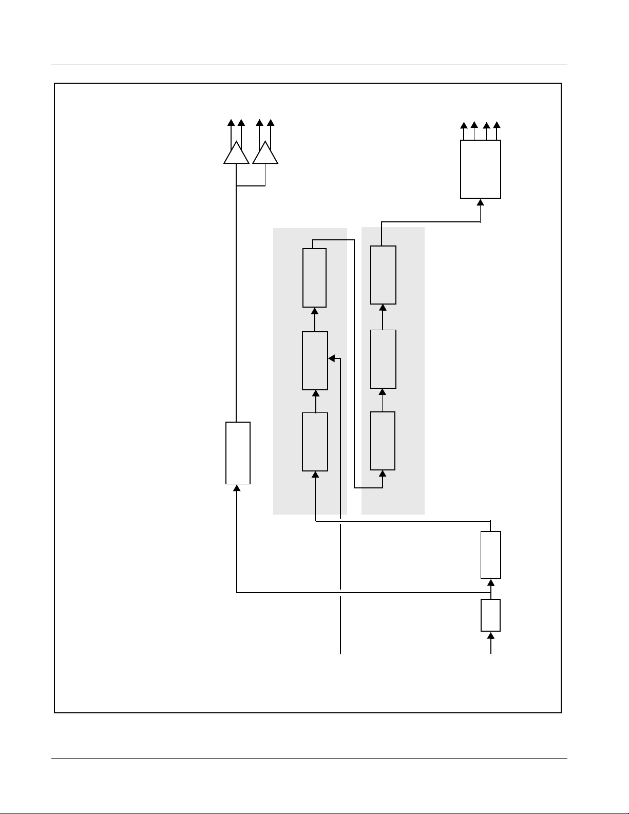
Figure 1-1 shows a functional block diagram of the 9084. The 9084 provides
HD/SD-SDI RGB color correction with frame synchronization that supports
all popular SD and HD video format s includin g 525i, 625i, 720 p, 720f, 1080i,
1080p, and 1080psF. Input video format is auto-detected by the card. The
9084 accepts either an HD SDI input (1.485 Gbit) or an SD SDI input (270
Mbit) and automatically equalizes for cable loss. The 9084 also provides
processing-bypassed reclocked SDI outputs.
Processed video is synchronized to either a frame-wide reference or a local
reference. For further flexibility in resolving system timing problems,
additional fixed delay can be added to the video. Ancillary Data (VANC) is
protected, and is passed from input to output ensuring data is not lost during
the frame sync operation.
9084 Input/Outputs
The 9084 provides the following video inputs and outputs:
• Inputs:
• HD/SD-SDI IN – dual-rate HD/SD-SDI input
• Outputs:
• HD/SD-SDI OUT – four dual-rate HD/SD-SDI buffered video
outputs
• RCK OUT – four dual-rate HD/SD-SDI reclocked buffered video
outputs
9084-OM (V4.0) 9084 PRODUCT MANUAL 1-5
Page 10
1 9084 Functional Description
RCK
OUT
SDI
OUT
Serializer/
Cable Drivers
AFD
Insertion
Sync
Frame
Video
Reclock
Processing
Video Processor
YCbCr
YCbCr
RGB
Correction
Limiting
Proc
Color Corrector
Deserialize
EQ
SDI IN
IN (1,2)
EXT REF
HD/SD
9084V4.0BD
Figure 1-1 9084 Functional Block Diagram
1-6 9084 PRODUCT MANUAL 9084-OM (V4.0)
Page 11

Introduction 9084 Functional Description
Color Corrector
The 9084 color corrector converts the YCbCr SDI input video to the 4:4:4
RGB color space (where the color correction is applied), and then back to
YCbCr SDI on the output. Controls are available to adjust each RGB level
independently for both white levels (gain) and black levels (offset). Gamma
can also be independently adjusted for each RGB channels. Various controls
can be ganged to provide adjustment for all three color channels
simultaneously.
Video Processor
The 9084 provides full video processing control (luma gain and lift, chroma
gain, and color phase) of the output video. The 9084 video processor also
provides white, black, and chroma clip control. Clipping can be applied with
either a hard or soft white clip and a lso a chroma saturation clip. Luma and
chroma gain controls can be ganged to provide adjustment for both gain
controls.
Frame Sync Function
AFD Inserter
This function p rovide s for fra me s ync co ntrol usin g e ither one of t wo ext ern al
EXT REF IN (1,2) reference sign als di stri buted wit h the ca rd fra me, or the inpu t
video as a frame sync reference.
This function allows horiz ontal and/or ver tica l of fset to be added bet ween the
output video and the frame sync reference.
A Reset Framesync function r esets the fra me sync following any horizontal or
vertical offset changes, clearing any buffered video and re-establishing the
frame sync .
In the event of input video loss of signal, this function provides for disabling
the video, going to a des ired color raster, or freezing to the last intact frame
(frame having valid SAV and EAV codes).
This function provides for assignment and insertion of AFD codes into the
SDI output video. Using this function, AFD codes in accordance with the
standard 4-bit AFD code designations can be applied to the output video.
This function checks for any existing AFD code within the received video
input. If a code is present, the code is displayed. When used in conjunction
with a separate downstream card capable of providing AFD-directed scaling,
the image can in turn b e scaled in accord ance with th e AFD coding embedd ed
by this card.
The function also allows the selection/changing of the AFD code and
ancillary data line number for the outputted AFD code.
9084-OM (V4.0) 9084 PRODUCT MANUAL 1-7
Page 12
1 9084 Functional Description
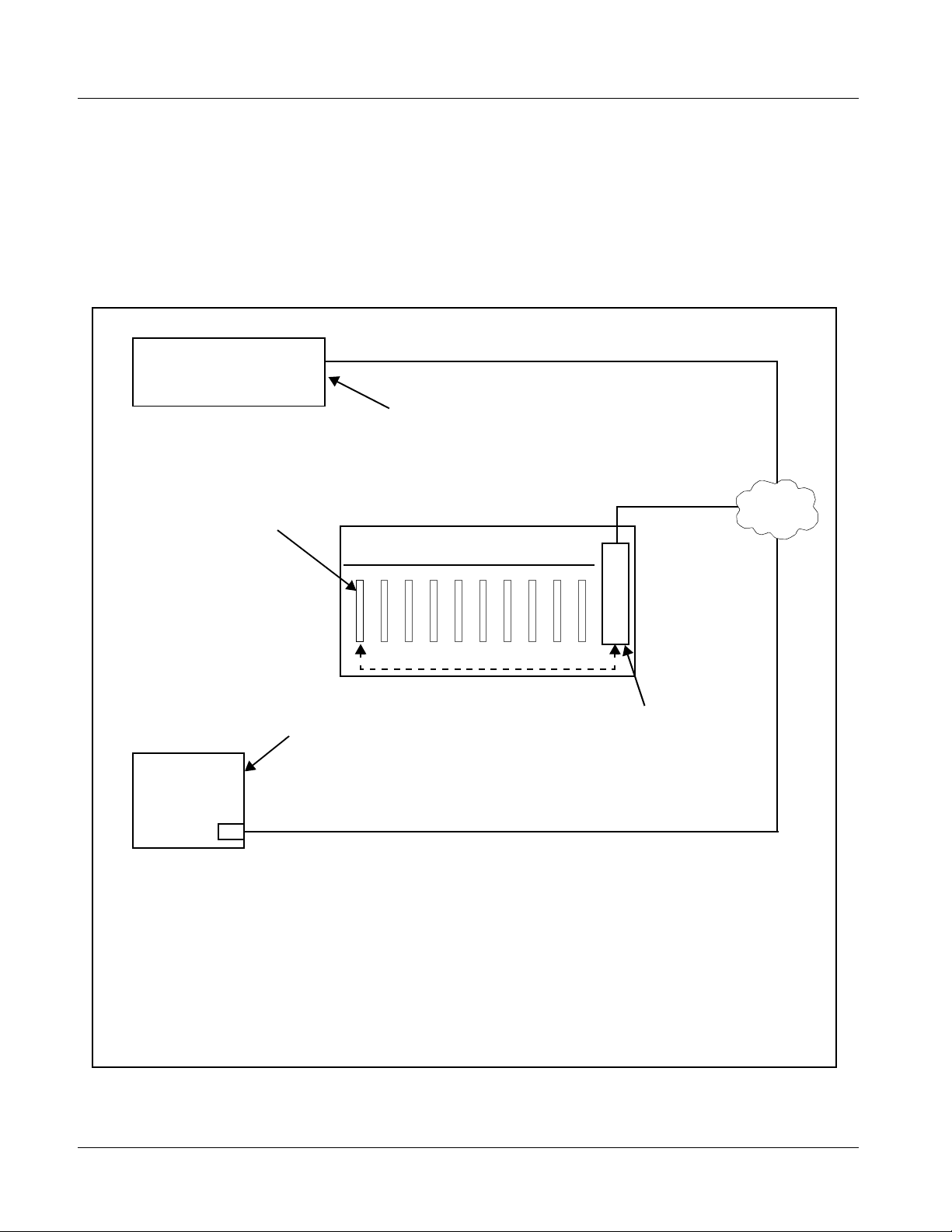
User Control Interface
Figure 1-2 shows the user control interface options for the 9084. These
options are individually described below.
Note: All user control interfaces described here are cross-compatible and can oper-
ate together as desired. Where applicable, any control setting change made
using a particular user interface is reflected on any other connected interface.
OGCP-9000/CC Control Panel
OGCP-9000 Control Panel
or
Remote Control Panel
Using the Control Panel,
9084 card can be remotely
controlled over a LAN
Card Edge Controls
9084 card can be
controlled using built-in
card edge controls
DashBoard™ Remote Control
Using a computer with
DashBoard™ installed, 9084
Computer
with NIC
Note: • To communicate with DashBoard™ or a Cobalt® OGCP-9000/CC or OGCP-9000 Control Panel,
the frame must have the optional MFC-8310-N or MFC-8320-N network controller card installed.
• DashBoard™ and the Remote Control Panels provide network control of the 9084 as shown. The
value displayed at any time on the card, or via DashBoard™ or a Control Panel is the actual value
as set on the card, with the current value displayed being the actual value as effected by the card.
Parameter changes made by any of these means are universally accepted by the card (for
example, a change made using the card controls will change the setting displayed on
DashBoard™ and a Control Panel; a change made using DashBoard™ will similarly change the
setting displayed on a Control Panel and the card itself).
card can be remotely controlled
over a LAN
8310-C / 8321-CN Frame with Network
Controller Card
In conjunction with a frame equipped
with a Network Controller Card, 9084
card can be remotely controlled over
a LAN
LAN
Figure 1-2 9084 User Control Interface
1-8 9084 PRODUCT MANUAL 9084-OM (V4.0)
Page 13

Introduction 9084 Functional Description
• Built-in Card Edge User Interface – Using the built-in card edge
controls and display, card control settings can be set using a front
panel menu which is described in Chapter 3,“Operat ing Inst ruction s”.
Note: Some of the 9084 functions described in this manual are available only when
using the DashBoard™, or Cobalt
Panels user interfaces.
• DashBoard™ User Interface – Using DashBoard™, the 9084 and
other cards installed in openGear™ frames such as the Cobalt
®
OGCP-9000 or OGCP-9000/CC Control
®
8310-C Frame can be controlled from a computer and monitor.
DashBoard™ allows users to view all frames on a network with
control and monitoring for all populated slots inside a frame. This
simplifies the setup and use of numerous modules in a large
installation and offers the ability to centralize monitoring. Cards
define thei r controllable parameters to DashBoard™, so the control
interface is always up to date.
The DashBoard™ software can be downloaded from the Cobalt
Digital Inc. website: www.cobaltdigital.com
(enter “DashBoard” in
the search window). The DashBoard™ user interface is describe d in
Chapter 3,“Operating Instructions”.
Note: If network remote control is to be used for the frame and the frame has not yet
been set up for remote control, Cobalt
Remote Control User Guide” (PN 9000RCS-RM) pr ovides thorough information and step-by-step instructions for setting up network remote control of
COMPASS™ cards using DashBoard™.
Download a copy of this guide by clicking on the Support>Downloads link at
www.cobaltdigital.com and then select DashBoard Remote Control Setup
Guide as a download, or contact Cobalt
Inc. (p. 1-15).
®
reference guide COMPASS™
®
as listed in Contact Cobalt Digital
• Cobalt
®
OGCP-9000/CC and OGCP-9000 Remote Control
Panels – The OGCP-9000/CC and OGCP-9000 Remote Control
Panels conveniently and intuitively provide parameter monitor and
control of the 9084 and other video and audio processing terminal
equipment meeting the open-architecture Cobalt COMPASS™ cards
for openGear™ standard.
In addition to circumventing the need for a computer to monitor and
control signal processing cards, the Control Panels allow quick and
intuitive acces s to hundre ds of car ds in a fac ility, and can monitor and
allow adjustment of multiple parameters at one time.
The Remote Control Panels are totally compatible with the
openGear™ control software DashBoard™; any changes made with
either system are reflected on the other. The Remote Control Panel
user interface is described in Chapter 3,“Operating Instructions”.
9084-OM (V4.0) 9084 PRODUCT MANUAL 1-9
Page 14
1 9084 Functional Description
Note: Although the OGCP-9000 Remote Control Panel can be used with the 9084,
the OGCP-9000/CC Remote Control Panel is specifically designed for use
with 9084 cards and provides the most intuitive and simplest interface of all
the methods described.
9084 Rear I/O Modules
The 9084 physically interfaces to system video connections at the rear of its
frame using a Rear I/O Module.
All inputs and outputs shown in the 9084 Functional Block Diagram (Figure
1-1) enter and exit the card via the card edge backplane connector. The
Rear I/O Module breaks out the 9084 card edge connections to BNC
connectors that interface with other components and systems in the signal
chain.
These required BNC connections are provided by either an 8310-BNC or
8310-C-BNC frame (which both have a built-in BNC connector backplane
module), or by using an optional RM-9084-A Rear I/O Module.
Video Formats Supported by the 9084
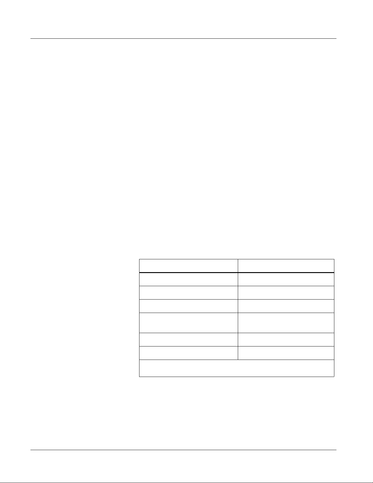
The 9084 supports all current SMPTE standard SD and HD video formats.
Table 1-1 lists the video formats supported by the 9084.
Table 1-1 Supported Video Formats
Raster Structure Frame Rate
1080psF 23.98; 24
1080p 23.98; 24
1080i
720p 23.98; 24; 25; 29.97; 30; 50;
486i
575i
(1) All rates displayed as frame rates; interlaced (“i”) field rates are two times the rate
value shown.
(1)
(1)
(1)
25; 29.97; 30
59.94; 60
29.97
25
1-10 9084 PRODUCT MANUAL 9084-OM (V4.0)
Page 15

Introduction Technical Specifications
Technical Specifications
Table 1-2 lists the technical specifications for the 9084 HD/SD-SDI RGB
Color Corrector with YCbCr Video Proc and Frame Sync card.
Table 1-2 Technical Specifica tions
Item Characteristic
Part number, nomenclature 9084 HD/SD-SDI RGB Color Corrector with YCbCr Video Proc
and Frame Sync
Installation/usage environment Intended for installation and usage in frame meeting openGear™
modular system definition.
Power consumptio n < 15 Watts maximum
Environmental:
Operating temperature:
Relative humidity (operating or storage):
Frame communication 10/100 Mbps Ethernet with Auto-MDIX.
32° – 104° F (0° – 40° C)
< 95%, non-condensing
Indicators Card edge display and indicators as follows:
• 4-character alphanumeric display
• Status/Error LED indicator
• Input For mat LED indic ato r
Controls Card edge switches as follows:
• Menu Enter pushbutton switch
• Menu Exit pushbutton switch
• Up/down selection toggle switch
Serial Digital Video Input Data Rates Supported:
SMPTE 292 HD-SDI: 1.485 Gbps or 1.485/1.001 Gbps
SMPTE 259M-C SD-SDI: 270 Mbps
HD Frame Rates Supported:
720p 23.98; 24; 25; 29.97; 30; 50; 59.94
1080i 25; 29.97
1080p 23.98; 24; 25; 29.97; 30
1080p/sF 23.98; 24
9084-OM (V4.0) 9084 PRODUCT MANUAL 1-11
Page 16

1 Technical Specifications
Table 1-2 Technical Specifications — continued
Item Characteristic
Serial Digital Video Input (cont.) SD Frame Rates Supported:
486i 29.97 (NTSC)
575i 25 (PAL)
Impedance:
75 Ω terminating
Equalization (HD):
328 ft (100 m) Belden 1694A
Equalization (SD):
1000 ft (305 m) Belden 1694A
Return Loss:
> 15 dB at 5 MHz – 1.485 GHz
Post-Processor Serial Digital Video
Outputs
Number of Outputs:
Four HD/SD-SDI BNC per IEC 60169-8 Amendment 2
Impedance:
75 Ω
Return Loss:
> 15 dB at 5 MHz – 270 MHz
> 12 dB at 270 MHz – 1.485 GHz
Signal Level:
800 mV ± 10%
DC Offset:
0 V ± 50 mV
Jitter (HD):
< 0.15 UI (all outputs)
Jitter (SD):
< 0.10 UI (all outputs)
Overshoot:
< 0.2% of amplitude
Pre-Proces sor (Rec locked) Se rial Digi tal
Video Outputs
1-12 9084 PRODUCT MANUAL 9084-OM (V4.0)
Number of Outputs:
Four HD/SD-SDI BNC per IEC 60169-8 Amendment 2
Impedance:
75 Ω
Page 17

Introduction Technical Specifications
Table 1-2 Technical Specifica tions — continued
Item Characteristic
Pre-Processor (Reclocked) Serial Digital
Video Outputs (cont.)
Reference Video Input Number of Inputs:
Return Loss:
> 15 dB at 5 MHz – 270 MHz
> 12 dB at 270 MHz – 1.485 GHz
Signal Level:
800 mV ± 10%
DC Offset:
0 V ± 50 mV
Jitter (HD ):
< 0.15 UI (all outputs)
Jitter (SD ) :
< 0.10 UI (all outputs)
Overshoot:
< 0.2% of amplitude
Two Non-Terminating (looping) Frame Reference Inputs
Standards Supported (HD):
720p 24; 25; 29.97; 30; 50; 59.94
1080i 25; 29.97
1080p 23.98; 24; 25; 29.97; 30
1080psF 23.98; 24
Standards Supported (SD):
486i 29.97 (NTSC)
575i 25 (PAL)
Signal Level:
1 Vp-p nominal
Signal Type:
Analog video sync (black burst or tri-level)
Impedance:
75 Ω
Return Loss:
> 30 dB to 30 MHz
Allowable Maximum DC on Ref Input:
±1.0 V
9084-OM (V4.0) 9084 PRODUCT MANUAL 1-13
Page 18

1 Warranty and Service Information
Warranty and Service Information
Cobalt Digital Inc. Limited Warranty
This product is warranted to be free from defects in material and workmanship for a period of five (5)
years from the date of shipment to the original purchaser, except that 4000, 5000, 6000, 8000 series
power supplies, and Dolby
material and workmanship for a period of one (1) year.
Cobalt Digital Inc. 's (“Cobalt”) sole obligation under this warranty shall be limited to, at its option, (i)
the repair or (ii) replacement of the product, and the determinati on of whether a defect is covered under
this limited warranty shall be made at the sole discretion of Cobalt.
This limited warranty applies onl y to the original end-purchaser of the pr oduct, and is not assigna ble or
transferrable therefrom. This warranty is limited to defects i n material a nd workman shi p, and shal l not
apply to acts of God, accidents, or negligence on behalf of the purchaser, and shall be voided upon the
misuse, abuse, alteration, or modification of the product. Only Cobalt authorized factory
representatives are authorized to make repairs to the product, and any unauthorized attempt to repair
this product shall immediately void the warranty. Please contact Cobalt Technical Support for more
information.
®
modules (where applicable) are warranted to be free from defects in
To facilitate the resolution of warranty related issues , Cobalt recommends registering the product by
completing and returning a product registration form. In the event of a warrantable defect, the
purchaser shall notify Cobalt with a description of the problem, and Cobalt shall provide the purchaser
with a Return Material Authorization (“RMA”). For return, defective product s should be double boxed,
and sufficiently protected, in the original packaging, or equivalent, and shipped to the Cobalt Factory
Service Center, postage prepaid and insured for the purchase price. The purchaser should include the
RMA number, description of the problem encountered, date purchased, name of dealer purchased
from, and serial number with the shipment.
Cobalt Digital Inc. Factory Service Center
2406 E. University Avenue Office: (217) 344-1243
Urbana, IL 61802 USA Fax: (217) 344-1245
www.cobaltdigital.com Email: info@cobaltdigital.com
THIS LIMITED WARRANTY IS EXPRESSLY IN LIEU OF ALL OTHER WARRANTIES
EXPRESSED OR IMPLIED, INCLUDING THE WARRANTIES OF MERCHANTABILITY AND
FITNESS FOR A PARTICULAR PURPOSE AND OF ALL OTHER OBLIGATIONS OR
LIABILITIES ON COBALT'S PART. ANY SOFTWARE PROVIDED WITH, OR FOR USE WITH,
THE PRODUCT IS PROVIDED “AS IS.” THE BUYER OF THE PRODUCT ACK NOWLEDGES
THAT N O OTHER REPRESENTATIONS WERE MADE OR RELIED UPON WITH RESPECT TO
THE QUALITY AND FUNCTION OF THE GOODS HEREIN SOLD. COBALT PRODUCTS ARE
NOT AUTHORIZED FOR USE IN LIFE SUP PORT APPLICATIONS.
COBALT'S LIABILITY, WHETHER IN CONTRACT, TORT, WARRANTY, OR OTHERWISE, IS
LIMITED TO THE REPAIR OR REPLACEMENT, AT ITS OPTION, OF ANY DEFECTIVE
PRODUCT, AND SHALL IN NO EVENT INCLUDE SPECIAL, INDIRECT, INCIDENTAL, OR
CONSEQUENTIAL DAMAGES (INCL UDING LOST PROFITS), EVEN IF IT HAS BEEN
ADVISED OF THE POSSIBILITY OF SUCH DAMAGES.
1-14 9084 PRODUCT MANUAL 9084-OM (V4.0)
Page 19
Introduction Contact Cobalt Digital Inc.
Contact Cobalt Digital Inc.
Feel free to contact our friendly and professional support representatives for
any of the following:
• Name and address of your local dealer
• Product information and pricing
• Technical support
• Upcoming trade show i nformation
Phone: (217) 344-1243
Fax: (217) 344-1245
Web: www.cobaltdigital.com
General Information: info@cobaltdigital.com
Technical Support: support@cobaltdigital.com
9084-OM (V4.0) 9084 PRODUCT MANUAL 1-15
Page 20

This page intentionally blank
1-16 9084 PRODUCT MANUAL 9084-OM (V4.0)
Page 21

Chapter 2 Installation and Setup
Overview
This chapter contains the following information:
• Installing the 9084 Into a Frame Slot (p. 2-1)
• Installing a Rear I/O Module (p. 2-3)
• Setting Up 9084 Network Remote Control (p. 2-4)
Installing the 9084 Into a Frame Slot
Chapter 2
CAUTION
Heat and power distribution requirements within a frame may dictate specific
slot placement of cards. Cards with many heat-producing compon ents should
be arranged to avoid areas of excess heat build-up, particularly in frames
using only convection cooling. The 9084 has a moderate power dissipation
(15 W max.). As such, avoiding placing the card adjacent to other cards with
similar dissipation values if possible.
CAUTION
This device contains semiconductor devices which are
susceptible to serious damage from Electrostatic
Discharge (ESD). ESD damage may not be immediately
apparent and can affect the long-term reliability of the
device.
Avoid handling circuit boards in high static environments
such as carpeted areas, and when wearing synthetic fiber
clothing. Always use proper ESD handling precautions
and equipment when working on circuit boards and
related equipment.
9084-OM (V4.0) 9084 PRODUCT MANUAL 2-1
Page 22

2 Installing the 9084 Into a Frame Slot
Note: • If installing the 9084 in an 8310-C-BNC or 8310-BNC frame (which is
pre-equipped with a 100-BNC rear I/O module installed across the entire
backplane) or a slot already equipped with a suitable I/O module, proceed to
card installation steps below.
• If installing the 9084 in a slot with no rear I/O module, an optional
RM-9084-A Rear I/O Module is required before cabling can be connected.
Install the Rear I/O Module as described in Installing a Rear I/O Module (p.
2-3).
CAUTION
If required, make certain Rear I/O Module(s) are installed before installing the
9084 into the frame slot. Damage to card and/or Rear I/O Module can occur if
module installation is attempted with card already installed in slot.
Note: Check the packaging in which the 9084 was shipped for any extra items such
as a Rear I/O Module connection label. In some cases, this label is shipped
with the card and to be installed on the Rear I/O connector bank corresponding to the slot location of the card.
Install the 9084 into a frame slot as follows:
1. Determine the slot in which the 9084 is to be installed.
2. Open the frame front access panel.
3. While holding the card by the card edges, align the card such that the
plastic ejector tab is on the bottom.
4. Align the card with the top and bottom guides of the slot in which the
card is being installed.
5. Gradually slide the card into the slot. When re sistance is noticed, gently
continue pushing the card until its rear printed circuit edge terminals
engage fully into the rear I/O module mating connector.
CAUTION
If card resists fully engaging in rear I/O module mating connector, check for
alignment and proper insertion in slot tracks. Damage to card and/or rear I/O
module may occur if improper card insertion is attempted.
6.
Verify that the card is fully engaged in rear I/O module mating connector.
7. Close the frame front access panel.
8. Connect the input and output cables as shown in Figure 2-1.
9. Repeat steps 1 through 8 for other 9084 cards.
Note: The 9084 BNC inputs are internally 75-ohm terminated. It is not necessary to
terminate unused BNC inputs or outputs.
2-2 9084 PRODUCT MANUAL 9084-OM (V4.0)
Page 23

Installation and Setup Installing a Rear I/O Module
Note: To remove a card, press down on the ejector tab to unseat the card from the
rear I/O module mating connector. Evenly draw the card from its slot.
10. If network remote control is to be used for the frame and the frame has
not yet been set up for remote control, perform setup in accordance with
Setting Up 9084 Network Remote Control (p. 2-4).
Note: If installing a card in a frame already equipped for, and connected to
DashBoard™, no network setup is required for the card. The card will be discovered by DashBoard™ and be ready for use.
Both the built-in Rear I/O Modules on the 8310-BNC/
8310-C-BNC frames and the optional RM-9084-A Rear I/O
Module use the connector arrangements shown to the left.
Connect cabling as shown. Unused connectors do not
require external termination.
Figure 2-1 9084 Rear I/O Module Connections
Installing a Rear I/O Module
Note: This procedure is applicable only if a Rear I/O Module is not currently
installed in the slot where the 9084 is to be installed.
If installing the 9084 in a 8310-C-BNC or 8310-BNC frame (which is
pre-equipped with a 100-BNC rear I/O module installed across the entire
backplane) or a slot already equipped with a suitable I/O module, omit this
procedure and go to Installing the 9084 Into a Frame Slot (p. 2-1).
Install a Rear I/O Module as follows:
1. On the 8310 frame, determine t he slot in which the 9084 is to be instal led.
2. In the mounting area corresponding to the slot location, install
Rear I/O Module as shown in Figure 2-2.
9084-OM (V4.0) 9084 PRODUCT MANUAL 2-3
Page 24

2 Setting Up 9084 Network Remote Control
Align and engage mounting tab on Rear
I/O Module with the module seating slot
1
on rear of frame chassis.
DSCN3483A.JPG
Hold top of Rear I/O Module flush against
frame chassis and start the captive screw.
2
Lightly tighten captive screw.
DSCN3487A.JPG
Figure 2-2 Rear I/O Module Installation
Setting Up 9084 Network Remote Control
Perform remote control setup in accordance with Cobalt® reference guide
“COMPASS™ Remote Control User Guide” (PN 9000RCS-RM).
Note: • If network remote control is to be used for the frame and the frame has not
yet been set up for remote control, Cobalt
Remote Control User Guide (PN 9000RCS-RM) provides thorough information and step-by-step instructions for setting up network remote control of
COMPASS™ cards using DashBoard™. (Cobalt
OGCP-9000/CC Remote Control Panel product manuals have complete
instructions for setting up remote control using a Remote Control Panel.)
Download a copy of this guide by clicking on the Support>Downloads link
at www.cobaltdigital.com and then select DashBoard Remote Control Setup
Guide as a download, or contact Cobalt
Inc. (p. 1-15).
• If installing a card in a frame already equipped for, and connected to
DashBoard™, no network setup is required for the card. The card will be discovered by DashBoard™ and be ready for use.
®
reference guide COMPASS™
®
OGCP-9000 and
®
as listed in Contact Cobalt Digital
2-4 9084 PRODUCT MANUAL 9084-OM (V4.0)
Page 25

Overview
Chapter 3
Chapter 3 Operating Instructions
This chapter contains the following information:
• Control and Display Descriptions (p. 3-1)
• Accessing the 9084 Card via Remote Control (p. 3-10)
• Checking 9084 Card Information (p. 3-12)
• Ancillary Data Line Number Locations and Ranges (p. 3-13)
• 9084 Function Submenu List and Descriptions (p. 3-14)
• Color and Video Correction Examples Using the 9084 (p. 3-27)
• Troubleshooting (p. 3-34)
Control and Display Descriptions
This secti on describes the user interface co ntrols, indicators, and displays
(both on-card and remote controls) for using the 9084 card. The 9084
functions can be accessed and controlled using any of the user interfaces
described here.
The format in which the 9084 functional controls, indicators, and displays
appear and are used varies depending on the user interface being used.
Regardless of the user interface being used, access to the 9084 functions (and
the controls, ind icato rs, an d disp lays r elat ed to a particul ar f uncti on) fo llows a
general arrangement of Function Submenus under which related parameters
can be accessed (as described in Function Submenu/Parameter Submenu
Overview below).
After familiarizing yourself with the arrangement described in Function
Submenu/Parameter Submenu Overview, proceed to the subsection for the
particula r user interf ace being used. Descri ptions and general instructions for
using each of the three user interfaces are individually described in the
following subsections:
• 9084 Card Edge Controls, Indicators, and Display (p. 3-3)
• DashBoard™ User Interface (p. 3-7)
• Cobalt
®
Remote Control Panel User Interfaces (p. 3-9)
9084-OM (V4.0) 9084 PRODUCT MANUAL 3-1
Page 26

3 Control and Display Descriptions
Note: Instructions provided here are applicable for all available user control meth-
ods. However, DashBoard™ and the Remote Control Panel provide greatly
simplified user interfaces as compared to using the 9084 card edge controls.
For this reason, it is strongly recommended that DashBoard™ or a Remote
Control Panel be used for all 9084 applications other than the most basic
cases.
Note: Not all functions available using DashBoard™ or the Control Panel are avail-
able using the card edge controls.
Note: When a setting is changed, settings displayed on DashBoard™ (or the
Remote Control Panel) are the settings as effected by the 9084 card itself and
reported back to the remote control; the value displayed at any time is the
actual value as set on the card.
Function Submenu/Parameter Submenu Overview
The functions and related pa rameters avai lable on the 9084 car d are organ ized
into function submenus, which consist of parameter groups as shown below.
Figure 3-1 shows how the 9084 card an d its submenus ar e orga nized, and also
provides an overview of how navig ation is performed be tween cards, func tion
submenus, and parameters.
9084
Submenu a Submenu b
Individual Parameters
Each submenu consists of groups of parameters
related to the function submenu. Using the “Video
Proc” function submenu example, the individual
parameters for this function consist of various v ideo
processor parameters such as Luma Gain, Color Gain,
and so on.
• • •
If using DashBoard™ or a Remote Control Panel, the
desired 9084 card is first selected.
The desired function submenu is next
selected.
Function Submenus consist of parameter
groups related to a particular 9084 card
function (for example, “Video Proc”).
Submenu z
Figure 3-1 Function Submenu/Parameter Submenu Overvie w
3-2 9084 PRODUCT MANUAL 9084-OM (V4.0)
Page 27

Operating Instructions Control and Display Descriptions
9084 Card Edge Controls, Indicators, and Display
Figure 3-2 shows and describes the 9084 card edge controls, indicators, and
display.
4-Character Alphanumeric Display
MENU DEPTH
525
Input Format
Indicators
Menu Depth
Indicators
9084
Menu Selection
Exit Submenu Pushbutton
Enter Submenu Pushbutton
Toggle Switch
RMT
REF
ERR
1080
720
Status
Indicators
625
Item Function
Display Displays 4-digit abbreviated code showing menu and submenu selections. When in a menu displaying a
Menu
Selection
toggle switch
Enter Menu
Pushbutton
Exit Menu
Pushbutton
Input Format
Indicators
parameter setting, the display shows parametric scalar value (and +/- sign where applicable).
• When in a menu or submenu selection mode, moving the switch up or down toggles up and down through the
menu or submenu item choices.
• When in a mode where parameter setting is displayed, moving the switch up or down increase or decreases
the parametric value.
When pressed, selects and opens the current mode shown on the display. At this point, submenu choices within
the selected menu are now displayed. Pressing the pushbutton again goes deeper into the submenu, now
opening items subordinate to the selected submenu. In this manner, pressing the Enter Menu pushbutton
navigates into a menu and its submenus.
When pressed, moves in the opposite direction of the Enter Menu pushbutton. It closes the currently selected
submenu and moves to the next higher menu, eventually moving completely out of the item’s submenus. In this
manner, pressing the Exit Menu pushbutton navigates out of a menu and its submenus.
Four blue LEDs indicate the input signal raster format being received and locked onto by the 9084 (1080, 720,
625, 525). Continuous cycling of the LEDs indicates the 9084 has not locked onto a particular format (as in the
case of no signal input).
Menu Depth
Indicators
RMT LED Blue LED flashes when 9084 is receiving control message from remote network control (e.g., DashBoard™ or
REF LED Blue LED illuminates when 9084 is receiving valid framesync when set up for framesync reference.
ERR LED Red LED illuminates when 9084 unable to lock to framesync, or unable to lock to input standard.
Four green LEDs show the currently selected menu/submenu depth navigation.
• No LEDs indicate top-level menu items are now ready for selection.
• One LED indicates first submenu items (items subordinate to currently selected menu item) are now ready for
selection.
• Two LEDs indicates second submenu items (items subordinate to currently selected submenu item) are now
ready for selection.
• Three LEDs indicates third submenu items (items subordinate to currently selected submenu item) are now
ready for selection. Typically, this is the level where values can now be adjusted for a specific parameter.
• Four LEDs indicate fourth submenu items are now ready for selection. (This depth is not applicable to most
items.)
®
Cobalt
Remote Control Panel)
Figure 3-2 9084 Controls, Indicators, and Display
9084-OM (V4.0) 9084 PRODUCT MANUAL 3-3
Page 28

3 Control and Display Descriptions
9084 Card Edge Control Menu/Submenu Structure
(See below.) Using the menu system of gr oup men us and s ubmenus descr ib ed
earlier , the 908 4 parameter s/contr ols are or gani zed into men us and submenus .
As appropriate, a submenu similarly may have its own further additional
subordinate submenus.
Menu depth (as indicated by
Menu Depth 9084 Menu Depth LEDs)
Menu Group Item
Submenu 1
(Submenu 1 selection items)
Submenu 2
(Submenu 2 selection items)
Submenu 3
(Submenu 3 selection
items and/or parameter
values)
Submenu 4
(Submenu 4 selection
items and/or
parameter values)
Figure 3-3 shows an example of using the card edge controls to access the
Color Correction menu (along with some of its submenus) to adjust color
channel gain and 0-lev els. through in Figure 3-3 denote the discr ete
tasks required in performing the example setup using the 9084 card edge
controls.
In this example, the following adjustment is being performed:
• White Adjust Blue ( Blue channel gain) is cha nged from default uni ty
to 94.0.
none
1
2
3
4
A I
• Black Adjust Red (Red channel 0-level) is changed from default
unity to -10.0.
Due to the limited control available when using the card edge control user
interface, the navigation into and out of submenus shown in Figure 3-3 is
required to perform the adjustments described above.
3-4 9084 PRODUCT MANUAL 9084-OM (V4.0)
Page 29

Operating Instructions Control and Display Descriptions
Vid
A
B
C
D
E
F
Submenu Depth
12 34
ClrC
Proc
Enbl
On
Off
GAIN
GAMA
Enbl
Unty
OFFS
RED
GRN
BLUE
(gain
value)
Select a top-level menu item (in this example, select Vid
(Video Proc and Color Correction controls))
Press Enter Menu and in this example, select ClrC (Color
Correction). This selects the color correction function.
Press Enter Menu again and in this example, select Enbl
(Enable).
Press Enter Menu again and in this example, select On. This
turns on the controls for the selected function (in this example,
Color Correction).
Press Exit Menu and in this example, select GAIN. This allows
selection of an RGB channel gain control.
Press Enter Menu and select in this example, BLUE. Thi s
selects gain adjustment for the Blue channel.
Again press Enter Menu and in this example, select a gain value
of 94.0 for this channel using the toggle switch.
GAIN
G
H
GAMA
Enbl
Unty
OFFS
RED
GRN
BLUE
I
Card Edge Setup Abbreviated Diagram
In Table 3-2, “9084 Function Submenu List”
abbreviated diagrams (as shown above and
in the example to the right) show the
navigation required to access a particular
submenu item or parameter when using the
card edge controls.
In this example, Video Proc function is being
enabled.
(gain
value)
Press Exit Menu and go to submenu 2. In this example, select
OFFS. This allows selection of an RGB channel offset (black lift
level) control.
Press Enter Menu again and select in this example, RED. This
selects offset adjustment for the Red channel.
Again press Enter Menu and in this example, select an offset
value of -10.0 for this channel using the toggle switch.
Card Edge Control Menu:
Vid
1234
Proc
Enbl
On Set Video Proc to On
Off Set Video Proc to Off
Figure 3-3 Card Edge Controls Setup of Example Color Correction Function
9084-OM (V4.0) 9084 PRODUCT MANUAL 3-5
Page 30

3 Control and Display Descriptions
Card Edge Display Orientation, Brightness, and Timeout
Adjust
The card edge 4-Character Alphanumeric Display can be changed between
vertical or horizont al chara cter o rientation to suit the mounti ng positi on of the
card as shown and described below.
D
i
s
p
Disp
9084
9084
Vertical orientation displays characters as
shown above (in this example, “Disp”). Use
this orientation when a frame has cards
positioned vertically.
Figure 3-4 Card Edge Display Orientation
1.
Access the Displ (Display) menu.
2. Select between Horizontal or Vertical as shown below.
Card Edge Control Menu:
Disp
12
H/V
Horz Horizontal orientation
Vert Vertical orientation
Adjust the display brightness as described below.
1. Access the Displ (Display) menu.
2. Select from the relative brightne ss levels as shown below.
Card Edge Control Menu:
Disp
12
BRGT
100%
53%
40%
27%
20%
13%
6.6%
Horizontal orientation displays characters
as shown above (in this example, “Disp”).
Use this orientation when a frame has cards
positioned horizontally.
3-6 9084 PRODUCT MANUAL 9084-OM (V4.0)
Page 31

Operating Instructions Control and Display Descriptions
The timeout period from when a menu is entered to when the display times
outs (reverts to t he defaul t card mod el displ ay) can be adjuste d from 5 to 9999
seconds (166.7 minutes) as described below.
1. Access the Displ (Display) menu.
2. Use the up/down switch to enter the desired timeout value as shown
below.
Card Edge Control Menu:
Disp
12
TOUT
(value) Timeout value (in seconds)
DashBoard™ User Interface
(See Figure 3-5.) Th e 9084 fu nction submenus are or gani zed i n DashBoa rd™
using tabs (for example, “Color Correction” in Figure 3-5). When a tab is
selected, each parametric control or selection list item associated with the
function is displayed. Sc alar (numeric ) parametric val ues can then be adj usted
as desired using the GUI slider controls. Items in a list can then be selected
using GUI drop-down lists. (In this mann er , the setti ng ef fected using cont rols
and selection lists displayed in DashBoard™ are comparable to the submenu
items accessed and committed using the 9084 card edge controls.)
Figure 3-5 shows the same setup described in Figure 3-3 as performed using
DashBoard™. Note how this setup is greatly simplified using DashBoard™
with most of the discrete tasks ( through in Figure 3-3) performed
A I
with the card edge controls now rolled into simple actions using
DashBoard™.
9084-OM (V4.0) 9084 PRODUCT MANUAL 3-7
Page 32

3 Control and Display Descriptions
Set Enable to On
[
B – C in Figure 3-3]
Set Offset for Red
channel (Black Adj.
Red) to -10.0 using
direct numeric entry or
slider control
G – I in Figure 3-3]
[
Set Gain for Blue
channel (White Adj.
Blue) to 94.0 using
direct numeric entry or
slider control
D – F in Figure 3-3]
[
Select top-level menu item Color
Correction
A in Figure 3-3]
[
9084_CC_EX1.PNG
Figure 3-5 DashBoard™ Setup of Example Color Correction Function
3-8 9084 PRODUCT MANUAL 9084-OM (V4.0)
Page 33

Operating Instructions Control and Display Descriptions
Cobalt® Remote Control Panel User Interfaces
(See Figure 3-6.) Similar to the function submenu tabs using DashBoard™,
the Remote Control Panels have a Sel ect Submenu key that is used to displ ay
a list of function submenus. From this list, a control knob on the Control
Panel is used to select a function from the list of displayed function submenu
items.
When the desired function submenu is selected, each parametric control or
selection list item associated with the function is displayed. Scalar (numeric)
parametric values can then be adjusted as desired using the control knobs,
which act as potentiometers. Items in a list can then be selected using the
control knobs which correspondingly act as rotary switches. (In this manner,
the setting ef fected using control s a nd s el ection lists displ ayed on t h e Cont rol
Panel are comparable to the submenu it ems accessed and committ ed using the
9084 card edge controls.)
Figure 3-6 shows accessing a function submenu and its parameters (in this
example, “Color Corrector”) using the Control Pan el as compared t o using the
card edge c ontrols.
Color Corrector function
(among others) is
accessed using the Control
Panel Select Submenu
key. Color Corrector
function is selected from
the list of functions
(submenu items)
When the Color Corrector
function submenu is
selected, its related
parameters are now
displayed.
In this example, Red
channel Gain is adjusted
using the Red channel Gain
control knob.
Note: Refer to “OGCP-9000 Remote Control Panel Product Manual” (PN
OGCP-9000-OM) or “OGCP-9000/CC Remote Control Panel Product Manual” (PN OGCP-9000/CC-OM) for complete instructions on using the Control
Panels.
Card Edge Control Menu:
Vid
123
ClrC
Enbl
On Color Corrector On
CC3_3440AA.JPG
Card Edge Control Menu:
Vid
1234
ClrC
GAIN
RED Select Red channel
(value) Gain value
CC3_3420CCB.JPG
Figure 3-6 Control Panel Setup of Example Video Proc Function
9084-OM (V4.0) 9084 PRODUCT MANUAL 3-9
Page 34

3 Accessing the 9084 Card via Remote Control
Accessing the 9084 Card via Remote Control
Access the 9084 card using DashBoard™ or Cobalt® Remote Control Panel
as described below.
Accessing the 9084 Card Using DashBoard™
1. On the computer connected to the frame LAN, open DashBoard™.
2. As shown below, in the left side Basic View Tree locate the Network
Controller Card associated with the frame containing the 9084 card to be
accessed (in this example, “MFC-8310-N SN: 00108053”).
DB_ACCESS1.PNG
3. As shown below, expand the tree to access the cards within the frame.
Click on the card to be accessed (in this example,
“Slot 7: CDI-9084 Color Corrector 1A”).
.
9084_DB_ACCESS2A.PNG
As shown on the next page, when the card is accessed a DashBoard™
function submenu screen is displayed. (The particular submenu screen
displayed is the previ ously displayed screen from the last time the card
was accessed by DashBoard™).
3-10 9084 PRODUCT MANUAL 9084-OM (V4.0)
Page 35

Operating Instructions Accessing the 9084 Card via Remote Control
Card Access/Navigation
Tree Pane
Card Info
Pane
Card Function Submenu
and Controls Pane
Accessing the 9084 Card Using a Cobalt® Remote Control Panel
Press the Select Device key and select a card as shown in the exa mp le bel ow.
OGCP-CC3_3422A.JPG
The display shows the list
order number of the device that
is ready for selection
The display shows the devices assigned to the Control Panel.
• Rotate any knob to select from the list of devices. The device selected
using a knob is displayed with a reversed background (in this example,
“9084 #2”).
• Directly enter a device by entering its list number using the numeric
keypad, and then pressing Enter or pressing in any knob).
9084_DB_ACCESS2A3V4.PNG
9084-OM (V4.0) 9084 PRODUCT MANUAL 3-11
Page 36

3 Checking 9084 Card Information
Checking 9084 Card Information
The operating stat us and s oftwar e ver sion t he 90 84 card can be check ed using
the card edge control user interface or DashBoard™. Figure 3-7 shows and
describes the 9084 card i nformation screen using DashBoard ™ and accessi ng
card information using the card edge control us er interface.
Note: Proper operating status in DashBoard™ is denoted by green icons for the sta-
tus indicators shown in Figure 3-7. Yellow or red icons respectively indicate
an alert or failure condition. Refer to Troubleshooting (p. 3-34) for corrective
action.
The Tree View shows the cards
seen by DashBoard™. In this
example, Network Controller
Card MFC-8310-N (serial
number ...8055) is hosting a
9084 card in slot 7.
Software Version Number
Refer to these numbers to check that documentation (such as
this manual) matches the card’s Software Release Number
and Software Build Number. Use these numbers also when
communicating to Cobalt
®
regarding this card.
Power Consumption and Temperature Displays
This display shows the power consumed by the 9084 for
both the +12V and -7.5V rails, as well as key device
temperatures.
Status Displays
These displays show the status
the signal being received by the 9084. Green Settings
icon shows that any changes made on DashBoard™
are sucessfully saved on the card’s memory.
Checking Card Using
Card Edge Controls
Info
12
+POW
-POW
SWR#
SWB#
9084_CARD_INFO_V4.PNG
(value) +12V Watts consumed
(value) - 7 .5V Watts co nsumed
(value) Software Release Number
(value) Software Build Number
Figure 3-7 9084 Card Info Utility
3-12 9084 PRODUCT MANUAL 9084-OM (V4.0)
Page 37

Operating Instructions Ancillary Data Line Number Locations and Ranges
Ancillary Data Line Number Locations and Ranges
Table 3-1 lists the default output video VANC line number locations for
various ancillary data items processed or passed by the card.
Table 3-1 9084 Ancillary Data Line Number Locations/Ranges
Default Line No. / Range
Item
SD HD
AFD 12 (Note 2) 9 (Note 2)
ATC _ VITC 12 (locked) 9/8 (Note 2)
ATC_LTC — 10 (Note 2)
SDI VITC Waveform 14/16 (Note 2) —
Closed Captioning 21 (locked) 10 (Note 2)
Notes:
1. The card does not check for conflicts on a given line number. Make certain the selected line is available
and carrying no other data.
2. While range indicated by drop-down list on GU I ma y a llo w a particular range o f c hoi ces, the actual range
is automatically c lampe d (limi ted) to cer tain ranges to pre vent in adver tent confli ct with activ e pict ure a rea
depending on video format. Limiting ranges for various output formats are as follows:
Format Line No. Limiting Format Line No. Limiting Format Line No. Limiting
525i 12-19 720p 9-25 1080p 9-41
625i 9-22 1080i 9-20
Because line number allocation is not standardized for all ancillary items,
consideration should be given to all items when performing set-ups. Figure
3-8 shows an example of improper and corrected VANC allocation within a
525i5994 SD-SDI stream.
Conflict between fixed
SDATC_VITC and added
AFD both on VANC line 12
Conflict between fixed
SD ATC_VITC on line 12
and AFD (now on line 18)
resolved
SD ATC_VITC = 12
SD VITC
Waveform = 14/16
CC = 21
Card 1
SD ATC_VITC = 12
SD VITC
Waveform = 14/16
CC = 21
Card 1
AFD Insertion
attempted usin g
VANC line 12
(default)
AFD Insertion
corrected to us e
VANC line 18
SD ATC_VITC = 12
AFD = 12
SD VITC
Waveform = 14/16
CC = 21
Card n
SD ATC_VITC = 12
SD VITC
Waveform = 14/16
AFD = 18
CC = 21
Card n
Figure 3-8 Example VANC Line Number Allocation Example
9084-OM (V4.0) 9084 PRODUCT MANUAL 3-13
Page 38

3 9084 Function Submenu List and Descriptions
9084 Function Submenu List and Descriptions
Table 3-2 individually lists and describes each 9084 function submenu “tab”
and its rela ted list selections, controls, and parameters. Where helpful,
examples showing usage of a function are also provided. Table 3-2 is
primarily based upon using DashBoard™ to access each function and its
corresponding submenus and parameters.
Note: All numeric (scalar) parameters displayed on DashBoard™ can be changed
using the slider controls, arrows, or by numeric keypad entry in the corresponding numeric field. (When using numeric keypad entry, add a return after
the entry to commit the entry.)
Note: Table 3-2 also provides abbreviated menu structure charts showing the menu
structure for accessing the function/parameter using the card edge controls.
Where this is not shown for a particular control, this indicates the control is
not available using card edge controls.
If using card edge controls, refer to 9084 Card Edge Control Menu/Submenu
Structure (p. 3-4) and Figure 3-3 for an explanation and an example of card
edge control menu structure navigation.
On DashBoard™ itself and in Table 3-2, the function submenu items are
organized using tabs as shown below.
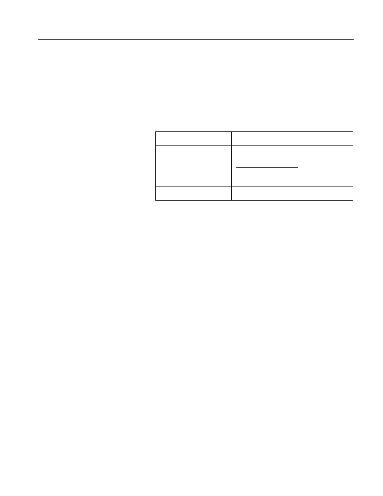
The table below provides a quick-reference to the page numbers where each
function submenu item can be found.
Function Submenu Item Page Function Submenu Item Page
Video Proc
AFD
Color Correction
3-15
3-18
3-19
Framesync
Presets
3-22
3-25
3-14 9084 PRODUCT MANUAL 9084-OM (V4.0)
Page 39

Operating Instructions 9084 Function Submenu List and Descriptions
Table 3-2 9084 Function Submenu List
Provides the following Video Proc parametr ic control s.
• Video Proc Video Proc (On/Off) provides master on/off control of all Video Proc
functions.
• When set to Off, Video Proc is bypassed.
• When set to On, currently displayed parameter settings take effect.
Card Edge Control Menu:
Vid
123
Proc
Enbl
On Video Proc On
Off Video Proc Off
• Reset to Unity Reset to Unity provides unity reset control of all Video Proc functions.
When Confirm is clicked, a Confirm? pop-up appears, requesting
confirmation.
• Click Yes to proceed with the unity reset.
Card Edge Control Menu:
Vid
123
Proc
Unty
Y? Move toggle switch in either
direction to confirm unity
reset. Reject reset by pressing
Exit Menu pushbutton.
• Click No to reject unity reset.
• Luma Gain Adjusts gain percentage applied to Luma (Y channel).
(0% to 200% range in 0.1% steps; unity = 100%)
Video Proc
Vid
• Luma Lift Adjusts lift applied to Luma (Y-channel).
Vid
Card Edge Control Menu:
123
Proc
Gain
(gain
value) Luma gain i n perc ent
Card Edge Control Menu:
123
Proc
Lift
(lift
value) Luma lift in perc ent
(-100% to 100% range in 0.1% steps; null = 0.0%)
9084-OM (V4.0) 9084 PRODUCT MANUAL 3-15
Page 40

3 9084 Function Submenu List and Descriptions
Table 3-2 9084 Function Submenu List — continued
(continued)
• Color Gain Adjusts gain percentage (saturation)
applied to Chroma (C-channel).
(0% to 200% range in 0.1% steps; unity = 100%)
Card Edge Control Menu:
Vid
123
Proc
Sat
(sat
value) Color gain in pe rcent
• Color Phase Adjusts phase angle applied to Chroma.
(-360° to 360° range in 0.1° steps; null = 0°)
Card Edge Control Menu:
Vid
123
Proc
Phas
(phase
value) Color phase angle a pplie d in
degrees
• Gang Luma and Color Gain When set to On, changing either the Luma Gain or Color Ga in controls
increases or decreases both the luma and chroma levels by equal
amounts.
Card Edge Control Menu:
Vid
123
Proc
Gang
On Gangin g On
Off Ganging Off
• Black Hard Clip Applies black hard clip (limiting) at specified percentage.
(-6.8% to 50.0%; null = -6.8%)
Card Edge Control Menu:
Vid
1234
Proc
Clip
BHCL
(value) Clip value in percent;
0.1% precision
3-16 9084 PRODUCT MANUAL 9084-OM (V4.0)
Page 41

Operating Instructions 9084 Function Submenu List and Descriptions
Table 3-2 9084 Function Submenu List — continued
(continued)
• White Hard Clip Applies white hard clip (limiting) at specified percentage.
(50.0% to 109.1%; null = 109.1%)
Card Edge Control Menu:
Vid
1234
Proc
Clip
WHCL
(value) Clip value in percent;
0.1% precision
• White Soft Clip Applies white soft clip (limiting) at specified percentage.
(50.0% to 109.1%; null = 109.1%)
Card Edge Control Menu:
Vid
1234
Proc
Clip
WSCL
(value) Clip value in percent;
0.1% precision
• Chroma Saturation Clip Applies chroma saturation clip (limiting) chroma saturation at specified
percentage.
(50.0% to 160.0%; null = 160.0%)
Card Edge Control Menu:
Vid
1234
Proc
Clip
CSAT
(value) Clip value in pe rcent;
0.1% precision
9084-OM (V4.0) 9084 PRODUCT MANUAL 3-17
Page 42

3 9084 Function Submenu List and Descriptions
Table 3-2 9084 Function Submenu List — continued
Allows assignment of AFD (Active Format Description)
AFD
Note: This function only marks the SDI output with an AFD code. Actual AFD processing must be performed by a downstream
card or system that recognizes an AFD code assigned here.
• Incoming AFD Displays incoming AFD setting as follows:
codes to the SDI output video.
• If AFD code is present, one of the 1 1, four-bit AFD codes is displayed (as
shown in the example to the left). Also displayed is the VANC line
number of the incoming AFD code.
• I f no AFD setting is present in the video signal, No AFD Present is
displayed.
• Output Mode Drop-down selection determines action to take in presence or absence of
existing AFD code on input video.
AFD
• Output Code Drop-down list assigns desired AFD to output SDI.
4:3 Coded Frame
AFD Code
•
•
•
16:9 Coded Frame
AFD Code
1: AFD codes numbering and definitions conform to SMPTE 2016-1-2007.
2: Image Prot ecte d impl ies pictu re cont ent that must not be cropped by
(1)
Description AFD Code
– No code present 1001 Full frame
0000 Undefined 1010 16:9 (center)
0010 Box 16:9 (top) 1011 14:9 (center)
0011 Box 14:9 (top) 1101 4:3 (with alternate
0100 Box > 16:9 (center) 1110 16:9 (with alternate
1000 Full frame 1111 16:9 (with alternate
(1)
Description AFD Code
– No code present 1001 4:3 (center)
0000 Undefined 1010 16:9 (image
0010 Full frame 1011 14:9 (center)
0011 4:3 (center) 1101 4:3 (with alternate
0100 Box > 16:9 (center) 1110 16:9 (with alternate
1000 Full frame 1111 16:9 (with alternate
conversion processes or display devices. Alternate center formats may
have protected center areas, with areas outside of the protected area not
containing mandatory content.
(1)
(1)
Description
14:9 center)
14:9 center)
4:3 center)
Description
protected)
14:9 center)
14:9 center)
4:3 center)
(2)
(2)
(2)
(2)
(2)
• Output Line Allows selecting the line location of the AFD data within the video signal
Ancillary Data space. (Range is 9 thru 41.)
Note: • Although the output line drop-down will allow any choice within the
9 thru 41 range, the actual range is automatically clamped (limited)
to certain ranges to prevent inadvertent conflict with active picture
area depending on video format. See Ancillary Data Line Number
Locations and Ranges (p. 3-13) for more information.
• The card does not check for conflicts on a given line number.
Make certain the selected line is available and carrying no other
data.
3-18 9084 PRODUCT MANUAL 9084-OM (V4.0)
Page 43

Operating Instructions 9084 Function Submenu List and Descriptions
Table 3-2 9084 Function Submenu List — continued
Provides color corrector functions for the individual RGB
channels of the received SD/HD SDI signal.
• Color Corrector Color Corrector (On/Off) provides master on/off control of all Color
Corrector functions.
• When set to Off, all processing is bypassed.
• When set to On, currently displayed parameters settings take effect.
Card Edge Control Menu:
Vid
123
ClrC
Enbl
On Color Corrector On
Off Color Corrector Off
• Reset to Unity Reset to Unity provides unity reset control of all Color Corrector
functions.
When Confirm is clicked, a Confirm? pop-up appears, requesting
confirmation.
Card Edge Control Menu:
Vid
123
ClrC
Unty
Y? Move toggle switch in either
direction to confirm unity
reset. Reject reset by pressing
Exit Menu pushbutton.
• Black Adj. (Green – Red – Blue) Separate red, green, and blue black level controls respectively apply lift
• Click Yes to proceed with the unity reset.
• Click No to reject unity reset.
value for R, G, and B channels.
(-100.0 to 100.0% range in 0.1% steps; null = 0.0)
Color Correction
Card Edge Control Menu:
Vid
1234
ClrC
OFFS
GRN Select G reen channel
BLUE Select Blue channel
RED Select Red channel
(value) Black (offset/lift) value in
percent (0.1% precision)
9084-OM (V4.0) 9084 PRODUCT MANUAL 3-19
Page 44

3 9084 Function Submenu List and Descriptions
Table 3-2 9084 Function Submenu List — continued
(continued)
• Gang Black Level Controls When set to On, changing any of the Black Adj. controls increases or
decreases R, G, and B black levels by equal amounts.
Card Edge Control Menu:
Vid
1234
ClrC
OFFS
GANG
On Ganging On
Off Ganging Off
• White Adj. (Green – Red – Blue) Separate red, green, and blue gain controls respectively apply gain
percentage for R, G, and B channels.
(0.0 to 200.0% range in 0.1% steps; unity = 100.0)
Card Edge Control Menu:
Vid
1234
ClrC
GAIN
GRN Select Gr een channe l
BLUE Sel ect Blu e channel
RED Select Red channel
(value) Gain value i n
percent (0.1% precision)
• Gang White Level Controls When set to On, changing any of the White Adj. (gain) controls increases
or decreases R, G, and B gain levels by equal amounts.
Card Edge Control Menu:
Vid
1234
ClrC
GAIN
GANG
On Ganging On
Off Ganging Off
3-20 9084 PRODUCT MANUAL 9084-OM (V4.0)
Page 45

Operating Instructions 9084 Function Submenu List and Descriptions
Table 3-2 9084 Function Submenu List — continued
(continued)
• Gamma (Green – Red – Blue) Separate red, green, and blue gamma controls respectively apply gamma
curve adjustment for R, G, and B channels.
(0.125 to 8.000 range in thousandths steps; unity = 1.000)
Card Edge Control Menu:
Vid
1234
ClrC
GAMA
GRN Select Green chan nel
BLUE Sel ect Blue channel
RED Select Red channel
(value) Gamma value in
percent (0.001% precision)
• Gang Gamma Controls When set to On, changing any of the Gamma controls increases or
decreases all Gamma settings by equal amounts.
Card Edge Control Menu:
Vid
1234
ClrC
GAMA
GANG
On Gangin g On
Off Ganging Off
9084-OM (V4.0) 9084 PRODUCT MANUAL 3-21
Page 46

3 9084 Function Submenu List and Descriptions
Table 3-2 9084 Function Submenu List — continued
Provides video Frame Sync and delay control tools.
Framesync
• Framesync Enable Disables the Frame Sync function, or selects from choices below.
• Off: Disables Frame Sync function; output video timing matches the
input video timing.
• Reference 1: Allows Frame Sync function to use external
Reference 1 as the reference standard.
• Reference 2: Allows Frame Sync function to use external
Reference 2 as the reference standard.
Note: If Reference 1 or Reference 2 is selected and an
appropriate external reference is not received, the
status portion of DashBoard™, indicating invalid frame sync
reference error. (Additionally, the card edge ERR indicator
illuminates indicating the same.) External reference signals
Reference 1 and Reference 2 are distributed to the card
and other cards via an 8310 frame bus.
• Input Video: Uses the input video signal as the
reference standard.
Note: If Input Video is used for framesync, any timing instability
on the input video will result in corresponding instability on
the output video.
indication appears in the Card Info
• Vertical Delay Control When Framesync is enabled, sets vertical delay (in number of lines of
• Horizontal Delay Control When Framesync is enabled, sets (in µsec of output video timing)
output video/forma t) between the output video and the frame sync
reference.
(Range is -1124 thru 1124 lines.)
Note: Lines refer to lines in the output video format, and not to the
reference format.
horizontal delay between the output video and the frame sync reference.
(Range is -64.000 thru 64.000 µsec)
Note: When an external framesync reference is used, the card will not
produce a framesync reset until the variance between framesync
reference and output video exceeds ± 2 clock periods. Therefore, a
framesync reset will not result if offsets within this window are
applied.
To apply an offset/framesync reset within this window, first apply a
relatively large offset, then apply the target smaller offset.
Example: T o apply a 1-period offset, first apply a 10-period positive
offset and then apply a 9-period negative offset. This results in the
target 1-period offset being applied to the output video.
3-22 9084 PRODUCT MANUAL 9084-OM (V4.0)
Page 47

Operating Instructions 9084 Function Submenu List and Descriptions
Table 3-2 9084 Function Submenu List — continued
(continued)
• Minimum Latency Frames Control
Minimum Latency Frames Control
• Video Delay Display Displays the current input-to-output video delay (in msec units) as well as
When Framesync is enabled, specifies the smallest amount of latency
allowed by the frame sync (latency measurement in output video frames).
The frame sync will not output a frame unless the specified number of
frames are captured in the buffer. The operational latency of the frame
sync is always between the specified minimum latency and
minimum latency plus one frame (not one field).
(Maximum range is 0 to 13.)
Note: Due to card memory limits, the maximum available Minimum
Latency Frames is related to the output video format selected.
For example, with a 1080i59.94 output, the maximum allowed
setting is 5. For a 1080i film (23.98) output, the maximum allowed
setting is 3. Conversely, greater maximum settings are allowed for
SD formats such as 525i59.94, where the practical maximum limit
is 13.
When using this control, be sure to check the Framesync Status
display as follows:
• Latency frames selection within limits.
• Latency frames selection exceeds limits.
in terms of Frames/fractional frame (in number of lines).
• Framesync Status Display Displays the current framesync status as follows:
• Framesync status OK.
• Framesync Enable set to Off.
• Improper or missing framesync reference.
• Latency frames selection exceeds limits.
Note: See Minimum Latency Frames Control (p. 3-23) for more
information about this message.
• Loss of Input Signal Sele c tion In the event of input video Loss of Signal (LOS), determines action to be
taken as follows:
• Disable Outputs: Disable all outputs.
• Freeze Last Frame: Freeze image to last good frame (last frame
having valid SAV and EAV codes).
• Freeze to Color: Freeze image to a color raster (as selected using
Framesync LOS Freeze Color control).
Note: If this card is used to also pass embedded audio, note that
audio noise will occur upon loss of input with “Freeze Last
Frame” selected.
9084-OM (V4.0) 9084 PRODUCT MANUAL 3-23
Page 48

3 9084 Function Submenu List and Descriptions
Table 3-2 9084 Function Submenu List — continued
(continued)
• Framesync LOS Freeze Color In the event of LOS with Freeze to Color enabled above, sets the image
• Custom Color Hue Adjusts raster hue (phase angle) for custom LOS color.
• Custom Color Saturation Adjusts raster saturation level for custom LOS color.
raster color from choices shown to the left.
(-360° to 360° range in 0.1° steps; null = 0°)
(0% to 100% range in 0.1% steps)
• Custom Color Y Level Adjusts raster luma level for custom LOS color.
(64 to 940 range)
• Reset Framesync
Reset Framesync
Resets the frame sync, clearing any buffered video.
When Confirm is clicked, a Confirm? pop-up appears, requesting
confirmation.
• Click Yes to reset the frame sync.
• Click No to reject rese t.
3-24 9084 PRODUCT MANUAL 9084-OM (V4.0)
Page 49

Operating Instructions 9084 Function Submenu List and Descriptions
Table 3-2 9084 Function Submenu List — continued
This function allows up to 16 card user settings
Presets
configuration presets to be saved in a Preset and then
recalled (loaded) as desired. All current settings (including
list selections and scalar (numeric) control settings such as
Gain, etc.) are saved when a Preset Save is invoked.
The Preset Name field and Preset Save button
allow custom user setting configurations to be
labeled and saved to a Preset for future use.
The Preset Load button and the Selected Preset
drop-down list allow saved presets to be selected
and loaded as desired. When a preset is loaded, it
immediately becomes active with all user settings
now automatically set as directed by the preset.
Saved presets can be uploaded to a computer for
use with other same-model COMPASS™ cards.
Each of the items to the left are described in detail on
the following pages.
• Preset Save and Load • Preset Save stores all current card control settings to the currently
• Selected Preset Selected Preset 1 thru Selected Preset 16 range in drop-down list
•
•
•
• Card Name Text entry field provides for optional entry of card name, function, etc. (as
selected preset.
(For example, if Preset 1 is selected in the Selected Preset drop-down
list, clicking and confirming Preset Save will then save all current card
control settings to Preset 1)
• Preset Load loads (applies) all card control settings defined by
whatever preset (Preset 1 thru Preset 16) is currently selected in the
Selected Preset drop-down list.
(For example, if Preset 3 is selected in the Selected Preset drop-down
list, clicking and confirming Preset Load will then apply all card control
settings defined in Preset 3)
The above buttons have a Confirm? pop-up that appears, requesting
confirmation.
Note: Applying a change to a preset using the buttons described above
rewrites the previous preset contents with the invoked contents.
Make certain change is desired before confirming preset change.
selects one of 16 stored presets as ready for Save (being written to) or for
Load (being applied to the card).
Note: The preset names shown to the left are the default (unnamed)
preset names. All 16 presets in this case are loaded identically with
the factory default settings.
shown in this example).
Note: Card name can be 31 ASCII characters maximum.
9084-OM (V4.0) 9084 PRODUCT MANUAL 3-25
Page 50

3 9084 Function Submenu List and Descriptions
Table 3-2 9084 Function Submenu List — continued
(continued)
• Reset Current Preset • Reset Current Preset resets all parameters (including preset custom
• Preset Name With one of 16 presets selected, provides for entry of custom name for the
name entered) of the currently selected Preset (as displayed in the
Selected Preset field) to factory default settings.
The above button has a Confirm? pop-up that appears, requesting
confirmation.
The factory default settings are as follows:
Function Parameter/Setting
Video Proc All parameters set to unity/null
settings.
Framesync F ram esyn c is disabled; Reference 1
or 2 must be selected to enable the
frame sync.
Color Correction All parameters set to unity/null
settings.
preset (as shown in example below).
Entering text in Preset
Name field (in this
example, “RCVR21”)
applies custom name to
selected Preset (in this
example, Preset 2)
Note: • Preset name can be seven ASCII characters maximum.
• The Preset ID number does not need to be entered; it is
added automatically.
• Download Presets Download Presets allows all 16 presets to be stored to a specified location
on a network computer for use with other same-model COMPASS™
cards.
®
Refer to Cobalt
Guide” (PN 9000RCS-RM) for instructions on using the Download Presets
function.
reference guide “COMPASS™ Remote Control User
3-26 9084 PRODUCT MANUAL 9084-OM (V4.0)
Page 51

Operating Instructions Color and Video Correction Examples Using the 9084
Color and Video Correction Examples Using the 9084
Shown below are examples of us ing the 9084 to prov ide par ametri c color and
video correction.
On-Set Monitor Color Correction Example
A typical use for the 9084 Color Corrector function is to provide color
correction for a monitor when an anchor desk set includes a monitor, as
shown in Figure 3-9.
In the example setup shown in Figure 3-9, a monitor is located behind the
anchor desk. When the camera inclu des the mon itor in its shot, typically the
color balance of the monitor will appear to be incorrect due to the
characteristics of the camera responding differently to the spectral light
emissions from the monitor as compared to the natural light spectra emissions
that exist a cross the set overall. This monitor color balance problem is a
function of the camera(s), and can vary with different camera models.
Feed To Switcher
Anchor Desk Set with Monitor
WFM 7120 Waveform
Monitor
TG700 Siggen
From Monitor Video Feed
Figure 3-9 Example Uncompensated Setup
9084-OM (V4.0) 9084 PRODUCT MANUAL 3-27
Page 52

3 Color and Video Correction Examples Using the 9084
Ideally, this display would essentially result in a waveform showing identical
RGB components corresponding to the grayscale monochrome bar spectrum
being fed to the set m onitor. However, as shown in Figure 3-10 with no
correction applied , the wa veform monit or shows i mbalance be tween the RGB
channels due to the reasons discussed above. Note the excessive offset, level,
and deviation from an ideal gamma curve for the blue channel.
Blue level in
excess of 100%
Non-ideal Gamma
curve
FA-3.PNG
Figure 3-10 Uncorrected (Uncompensated) Monitor Waveform
Black (Offset) level
negative
3-28 9084 PRODUCT MANUAL 9084-OM (V4.0)
Page 53

Operating Instructions Color and Video Correction Examples Using the 9084
Figure 3-11 shows the same setup using the 9084 Color Corrector function,
along with the appropriate signal source standard and a video waveform
monitor to assess and determine the color correction required. In the
calibration setup shown in Figure 3-11 the feed to the switcher is monitored
by a WFM 7120 Waveform Monitor, with the set monitor being fed a
monochrome linear limit ramp by a TG700 siggen.
Anchor Desk Set with Monitor
9084 Card
WFM 7120 Waveform
Monitor
To Switcher
Figure 3-11 Example Setup Using Control Panel Color Corrector Function
From Monitor Video Feed
TG700 Siggen
Using the 9084 Color Co rrector funct ion and setup s hown in Fi gure 3 -11, this
condition can be corrected through compensation using the 9084 Color
Corrector function as shown in Figure 3-12.
Note: As shown in Figure 3-12, a recommended approach to performing color cor-
rections is to first apply offset correction, then gain correction, and finally
gamma correction.
9084-OM (V4.0) 9084 PRODUCT MANUAL 3-29
Page 54

3 Color and Video Correction Examples Using the 9084
Uncompensated
Gain
(Left) Noting that the uncompensated black offset
for the blue channel is negative, a correspondingly
equivalent positive setting is applied using the blue
Corrected
Offset
channel Black offset control (in this example,
adjusting the Black offset from unity to 5.0 provides
compensation).
(Right) Noting that the uncompensated blue Gain
exceeds ideal 100% level, a correspondingly
smaller gain percentage setting is applied using the
blue channel Gain control until the gain is observed
as 100% (in this example, adjusting blue Gain from
unity to 87.5% provides compensation).
Corrected
Gain
FA-3A.PNG
Uncompensated black Offset
Uncompensated
Gamma
Corrected
Gamma
FA-3B.PNG
(Left) Noting that the uncompensated blue Gamma curve
indicates gamma factor is less than ideal 1.000, a
correspondingly greater numeric gamma factor is applied using
the blue channel Gamma control until the blue gamma function is
observed as linear (in this example, adjusting blue Gamma from
unity to 3.333 provides compensation).
FA-3C.PNG
(Left) Compensated Offset, Gain, and Gamma
are now symmetrical across all three color
channels, resulting in proper monitor
appearance in the OTA feed.
FA-3E.PNG
Figure 3-12 Applying Correction to Example Monitor Waveform Signal
3-30 9084 PRODUCT MANUAL 9084-OM (V4.0)
Page 55

Operating Instructions Color and Video Correction Examples Using the 9084
Miscellaneous Color and Video Correction Examples
Table 3-3 provides examples showing and des cri bi ng va ri ous col o r and v ide o
condition corrections using the 9084.
Note: Signal generator and waveform monitor used in these examples are
Tektronix
Table 3-3 Color and Video Corrections Using the 9084
®
models TG700 and WFM 7120, respectively.
Condition Observed On Waveform Monitor Correction Using 9084
Excessive red channel Gamma (as shown below for
SMPTE color bars on vectorscope display)
VAR1.PNG
Using the red channel Gamma control to reduce Gamma
factor, vectorscope display now shows correction with no
knee or curvature at intersection of axes.
VAR2.PNG
Excessive green channel lift/offset (as shown below for
SMPTE color bars on vectorscope display)
VAR3.PNG
Using the green channel Black control to reduce green
channel lift/offset, vectorscope display now shows no
droop along axis.
VAR2.PNG
9084-OM (V4.0) 9084 PRODUCT MANUAL 3-31
Page 56

3 Color and Video Correction Examples Using the 9084
Table 3-3 Color and Video Corrections Using the 9084 — continued
Condition Observed On Waveform Monitor Correction Using 9084
White (luma) level exceeding 100% level (as shown
below for limit ramp monochrome bars on waveform
monitor display)
VAR4.PNG
White (luma) level exceeding 100% level (as shown
below for limit ramp monochrome bars on waveform
monitor display)
Using the White Hard Clip control, a lowered white hard
clipping threshold is applied to now limit the level to 100%.
VAR4A.PNG
Using the White Soft Clip control, a lowered white soft
clipping threshold is applied to now limit the level to 100%.
VAR5.PNG
Luma gain less than 100% level (as shown below for
100% color bars on YPbPr waveform monitor display)
VAR9.PNG
Using the Luma Gain control to increase luma gain, luma
gain is now restored to 100%.
VAR5A.PNG
VAR9A.PNG
3-32 9084 PRODUCT MANUAL 9084-OM (V4.0)
Page 57

Operating Instructions Color and Video Correction Examples Using the 9084
Table 3-3 Color and Video Corrections Using the 9084 — continued
Condition Observed On Waveform Monitor Correction Using 9084
Chroma gain exceeds 100% level (as shown below for
100% color bars on YPbPr waveform monitor display)
VAR10.PNG
Leading color phase condition (as shown below for
SMPTE color b ars on vector display)
Using the Color Gain (Chroma) control to reduce chroma
gain, chroma gain is now restored to 100% level.
VAR10A.PNG
Using the Color Phase control to provide phase lag, color
phase condition is now correct ed.
Vectors are
advanced and do
not coincide with
0° points
VAR8.PNG
Vectors coincide
with 0° points
VAR8A.PNG
9084-OM (V4.0) 9084 PRODUCT MANUAL 3-33
Page 58

3 Troubleshooting
Troubleshooting
This section provides general troubleshooting information and specific
symptom/corrective action for the 9084 card. The 9084 card requires no
periodic maintenance in its normal operation; if any error ind ication (as
described in this section) occurs, use this section to correct the condition.
Error and Failure Indicator Overview
The 9084 card itself and its remote control systems all (to varying degrees)
provide error and failure indications. Depending on how the 9084 card is
being used (i.e, standalone or network controlled through DashBoard™ or a
Remote Control Panel), che ck all avai lable indi cations in the event of an error
or failure condition.
The various 9084 card and remote control error and failure indicators are
individually described below.
Note: The descriptions below provide general information for the various status and
error indicators. For specific failures, also use the appropriate subsection
listed below.
• Basic Troubleshooting Checks (p. 3-38)
• 9084 Processing Error Troubleshooting (p. 3-39)
• Troubleshooting Network/Remote Control Errors (p. 3-40)
3-34 9084 PRODUCT MANUAL 9084-OM (V4.0)
Page 59

Operating Instructions Troubleshooting
9084 Card Edge Status/Error Indicators and Display
Figure 3-13 shows and describes the 9084 card edge status indicators and
display. These indicators and the display show status and error conditions
relating to the card itself and remote (network) c ommunications (where
applicable). Because these indicators are part of the card itself and require no
external interface, the indicators are particularly useful in the event of
communications problems with external devices such as network remote
control devices.
4-Character Alphanumeric Display
RMT
REF
ERR
1080
720
625
525
9084
Status/Error
Indicators
Input Format
Indicators
Item Function
Alphanumeric
Display
RMT LED Blue LED flashes when 9084 is receiving control message from remote network control (e.g., DashBoard™
REF LED Blue LED illuminates indicating 9084 is receiving valid reference when set up for framesync operation.
ERR LED Red LED illuminates when 9084 unable to lock to framesync, or unable to lock to input standard.
Input Format
LEDs
Displays 4-digit alphanumeric code indicating status or errors as follows:
• E0XX: Video Errors
• E002: Video Acquiring Lock
• E2XX: Frame Sync Errors
• E200: Reference is Incompatible with Input Video
• E201: Reference Standard is Invalid/No Reference Present
• E202: Reference Standard is 720p2398 (a reference standard not supported by the framesync)
• E203: Reference Standard is 720p2997 (a reference standard not supported by the framesync)
®
or Cobalt
Four blue LEDs indicate the input signal raster format being received and locked onto by the 9084 (1080,
720, 625, 525). Continuous cycling of the LEDs indicates the 9084 has not locked onto a particular format (as
in the case of no signal input).
Remote Control Panel)
Figure 3-13 9084 Card Edge Status Indicators and Display
9084-OM (V4.0) 9084 PRODUCT MANUAL 3-35
Page 60

3 Troubleshooting
DashBoard™ Status/Error Indicators and Displays
Figure 3-14 shows and describes the DashBoard™ status indicators and
display. These indicator icons and displays show status and error conditions
relating to the 9084 card itself and remote (network) communications.
Indicator Icon or Display Error Description
Red indicator icon in Card Access/Navigation Tree pane shows card with Error
condition (in this example, the Card Access/Navigation Tree pane shows a general
error issued by the 9084 card in slot 7).
Specific errors are displayed in the Card Info pane (in this example “No connection
to device” indicating 9084 card is not connecting to frame/LAN).
If the 9084 card is not connecting to the frame or LAN, all controls are grayed-out (as
shown in the example here).
Gray indicator icon in Card Access/Navigation Tree pane shows card(s) are not
being seen by DashBoard™ due to lack of connection to frame LAN (in this
example, both a 9084 card in slot 7 and the MFC-8310-N Network Controller Card
for its frame in slot 0 are not being seen).
Yellow indicator icon in Card Access/Navigation Tree pane shows card with Alert
condition (in this example, the Card Access/Navigation Tree pane shows a general
alert issued by the MFC-8310-N Network Controller Card).
Clicking the card slot position in the Card Access/Navigation Tree (in this example
Network Controller Card “Slot 0: MFC-8310-N”) opens the Card Info pane for the
selected card. In this example, a “Fan Door Open” specific error is displayed.
Yellow indicator icon in 9084 Card Info pane shows error alert, along with cause for
alert (in this example, the 9084 is receiving no video input, or a video input that is
invalid for the card and/or its current settings).
Where available, error messages within a function submenu pane show highly
specific information relating to detected errors (in this example, message shows an
invalid or missing Framesync Enable reference selection).
Figure 3-14 DashBoard™ Status Indicator Icons and Display
3-36 9084 PRODUCT MANUAL 9084-OM (V4.0)
Page 61

Operating Instructions Troubleshooting
Access Card Info panes for specific cards by clicking the card slot position in
the Card Access/Navigation Tree pane (as shown in the example in Figure
3-15).
By clicking on “Slot 0: MFC-8310-N”
in this example, Card Info is
displayed for frame Network
Controller Card
By clicking on “Slot 7:
CDI-9084 Color Corrector 1A”
in this example, Card Info is
shown for 9084 card in slot 7
Status for selected card is
shown here (in this
example, connection OK
and “Fan Door Open”
alert)
Card general information
is displayed in lower
portion of Card Info pane
9084_TS_CARD_INFO_ACCESS.PNG
Status for selected
card is shown here
(in this example, all
indications are OK)
Where applicable,
additional status is
displayed (as shown in
this example)
9084_CARD_INFO_V4.PNG
Figure 3-15 Selecting Specific Cards for Card Info Status Display
9084-OM (V4.0) 9084 PRODUCT MANUAL 3-37
Page 62

3 Troubleshooting
Basic Troubleshooting Checks
Failures of a general nature (affecting many cards and/or functions
simultaneously), or gross inoperability errors are best addressed first by
performing basic checks before proceeding further. Table 3-4 provides basic
system checks that typically locate the source of most general problems. If
required and applicable, perform further troubleshooting in accordance with
the other troubleshooting tables in this section.
Table 3-4 Basic Troubleshooting Checks
Item Checks
Verify power presence and
characteristics
Check Cabl e connection
secureness and connecting
points
Card seating within slots Make certain all cards are properly seated within its frame slot. (It is best to assure
Check status indicators and
displays
Troubleshoot by substitution All cards within the frame can be hot-swapped, replacing a suspect card or module
• On both the frame Network Contro ller Card and t he 9084, in all cases when po wer is
being properly supplied there is always at least one indicator illuminated. Any card
showing no illuminated indicators should be cause for concern.
• Check the Power Consumed indications for both the +12 V and -7.5 V supply rails
for the 9084 card. This can be observed using the DashBoard™ Card Info pane, or
using the card edge controls and indicators as shown in Figure 3-7 on page 3-12.
• If either of the rail supplies show no power being consumed, either the frame
power supply, connections, or the 9084 card itself is defective.
• If either of the rail supplies show excessive power being consumed (see
Technical Specifications (p. 1-11) in Chapter 1, “Introduction”), the 9084 card
may be defective.
Make certain all ca ble connec tions are ful ly secure (inc luding coa xial cable att ach ment
to cable ferrules on BNC connectors). Also, make certain all connecting points are as
intended. Make certain the selected connecting points correlate to the intended card
inputs and/or outputs. Cabling mistakes are especially easy to make when working
with large I/O modules.
proper seating by ejecting the card and reseating it again.)
On both DashBoard™ and the 9084 card edge indicators, red indications signify an
error condition. If a st atus indic ator sig nifies an error, proceed to the following tables in
this section for further action.
with a known-good item.
3-38 9084 PRODUCT MANUAL 9084-OM (V4.0)
Page 63

Operating Instructions Troubleshooting
9084 Processing Error Troubleshooting
Table 3-5 provides 9084 processing troubleshooting information. If the 9084
card exhib its any of the symptoms listed in Table 3-5, follow the
troubleshooting instructions provided.
In the majority of cases, most errors are caused b y simple errors where th e
9084 is not appropriately set for the type of signal being received by the card.
Note: The error indications shown below are typical for the corresponding error con-
ditions listed. Other error indications not specified here may also be displayed
on DashBoard™ and/or the 9084 card edge status indicators.
Note: Where errors are displayed on both the 9084 card and network remote con-
trols, the respective indicators and displays are individually described in this
section.
Table 3-5 Troubleshooting Processing Errors by Symptom
Symptom Error/Condition Corrective Action
• DashBoard™ shows Video
yellow icon and Input Invalid
message in 9084 Card Info
pane.
• Card edge Input Format LEDs
show continuous cycling.
• DashBoard™ shows Frame
Sync red icon and Reference
Invalid message in 9084 Card
Info pane.
• Card edge red ERR indicator
illuminated.
No video input present Make certain intended vid eo sou r ce is
connected to appropriate 9084 ca rd video input.
Make certain BNC cable connections between
frame Rear I/O Module for the card and signal
source are OK.
Frame sync r eference not
properly selected or not being
received
• If external frame sync reference is not
intended to be used, make certain the
Framesync Enable selection list is set to Off
or Input Video as desired.
• If external frame sync reference is i ntended to
be used, make certain selected external
frame sync reference is active on frame sync
8310 frame bus. (External reference signals
Reference 1 and Reference 2 are distributed
to the 9084 and other cards via an 8310
frame bus.) Refer to Framesync function
submenu tab on page 3-22 for more
information.
9084-OM (V4.0) 9084 PRODUCT MANUAL 3-39
Page 64

3 Troubleshooting
Table 3-5 Troubleshooting Processing Errors by Symptom — continued
Symptom Error/Condition Corrective Action
DashBoard™ shows
Framesync St atu s error
message in 9084 Framesync
function submenu screen.
Ancillary data (closed cap tioning,
timecode, AFD, etc.) not
transferred through 9084.
Specifi ed Mi nim um Laten cy
Frames setting exceeds 9084
card buffer space for the
selected output video format
• Control(s) not enabled • Make certain respective control is set to On or
• VANC line number conflict
between two or more
ancillary data items
Troubleshooting Network/Remote Control Errors
Refer to Cobalt® reference guide “COMPASS™ Remote Control User
Guide” (PN 9000RCS-RM) for network/remote control troubleshooting
information.
• Reduce the Minimum Latency Frame s setti ng
as specified in the error message to correct
the error.
Note: Due to card mem ory limits, the maximum
available Minimum Latency Frames is
related to the output video format.
For example, with a 1080i59.94 output, the
maximum allowed setting is 5. For a 1080i
film (23.98) output, the maximum allowed
setting is 3. Conversely, greater maximum
settings are allowed for SD formats such as
525i59.94, where the practical maximum
limit is 13.
Enabled (as appropriate).
• Make certain each ancillary data item to be
passed is assigned a uni que line number (se e
Ancillary Data Line Number Locations and
Ranges on page 3-13).
In Case of Problems
Should any problem arise with this product that was not solved by the
information in this section, please contact the Cobalt Digital Inc. Technical
Support Department.
If required, a Return Material Authorization number (RMA) will be issued to
you, as well as specific shipping instructions. If required, a temporary
replacement item will be made available at a nominal charge. Any shipping
costs incurred are the customer’s responsibility. All products shipped to you
from Cobalt Digital Inc. will be shipped collect.
The Cobalt Digital Inc. Technical Support Department will continue to
provide advice on any product manufactured by Cobalt Digital Inc., beyond
the warranty period without charge, for the life of the product.
See Contact Cobalt Digital Inc. (p. 1-15) in Chapter 1, “Introduction“for
contact in formation.
3-40 9084 PRODUCT MANUAL 9084-OM (V4.0)
Page 65

Page 66

Cobalt Digital Inc.
2406 E. University Ave.
Urbana, IL 61802
Voice 217.344.1243 • Fax 217.344.1245
www.cobaltdigital.com
9084-OM (V4.0) Printed in USA
 Loading...