


276 Owner’s Manual
GENERAL INFORMATION
WELCOME ................................................................................................ 1-1
CERTIFICATE OF LIMITED WARRANTY ................................................ 1-2
INTRODUCTION ....................................................................................... 1-4
OWNER RESPONSIBILITY/WARRANTY PROCEDURE ......................... 1-5
CERTIFICATIONS ..................................................................................... 1-6
FEATURES/CONSTRUCTION .................................................................. 1-6
WARNING LABELS ................................................................................... 1-7
PUBLICATIONS......................................................................................... 1-9
NAUTICAL TERMS.................................................................................... 1-9
SYMBOLS ................................................................................................ 1-12
SPECIFICATIONS ................................................................................... 1-13
LAYOUT ................................................................................................... 1-14
PROPELLER APPLICATION CHART ..................................................... 1-15
ALPHABETICAL INDEX .......................................................................... 1-16
T
ABLE
Intended Use........................................................................................ 1-4
Craft Design Category.......................................................................... 1-4
Before Operating .................................................................................. 1-5
Warranty Service Requirements .......................................................... 1-5
Extended Service Agreement............................................................... 1-5
If You Sell Your Cobalt Boat................................................................. 1-5
NMMA .................................................................................................. 1-6
MerCruiser............................................................................................ 1-6
Volvo Penta .......................................................................................... 1-6
Amenities.............................................................................................. 1-6
Construction Standards/Certifications .................................................. 1-6
Serial Number Locations ...................................................................... 1-6
OF
C
ONTENTS
276 Owner’s Manual
i

COBALT
RESPONSIBILITIES AND SAFETY
OWNER/OPERATOR RESPONSIBILITIES .............................................. 2-1
Registration/Documentation ................................................................ 2-1
Required Safety Equipment ................................................................. 2-2
Recommended Safety Equipment ....................................................... 2-2
Recommended Spare Parts................................................................. 2-3
Education Opportunities....................................................................... 2-3
Insurance ............................................................................................ 2-3
BOAT THEORY ........................................................................................ 2-3
Remote Control System ....................................................................... 2-3
Steering System ................................................................................... 2-3
Fuel System ......................................................................................... 2-3
Ventilation System ............................................................................... 2-3
Electrical Systems ................................................................................ 2-4
Cooling System .................................................................................... 2-4
Exhaust System ................................................................................... 2-4
Lubrication System............................................................................... 2-4
Seaworthiness Inspection .................................................................... 2-4
Operation Checklist ............................................................................. 2-4
Environmental Considerations ............................................................. 2-5
Components, Maintenance and Repairs.............................................. 2-7
Emergency Considerations .................................................................. 2-7
Lifesaving Equipment ........................................................................... 2-9
SAFETY ................................................................................................... 2-12
Signal Words/Definitions.................................................................... 2-12
General Safety ................................................................................... 2-12
Water Sports Safety ........................................................................... 2-18
Safety Alert From August 28, 2001: ................................................... 2-20
Navigation ......................................................................................... 2-20
Aids to Navigation .............................................................................. 2-22
276
BOWRIDER
OPERATING INFORMATION
PRECAUTIONS ......................................................................................... 3-1
Before You Start................................................................................... 3-1
Fire/Explosion ...................................................................................... 3-1
FIRST-TIME OPERATION......................................................................... 3-1
FUEL .......................................................................................................... 3-2
Fuel Requirements............................................................................... 3-2
Fueling ................................................................................................. 3-2
LAUNCHING .............................................................................................. 3-4
Launching Checklist............................................................................. 3-4
On the Water........................................................................................ 3-4
Boarding ............................................................................................... 3-4
Loading ................................................................................................ 3-4
Shipshape ............................................................................................ 3-4
ii
276 Owner’s Manual

T
ABLE OF
GETTING UNDERWAY ............................................................................. 3-5
Before Starting Checklist ...................................................................... 3-5
Handling Dock and Mooring Lines ....................................................... 3-6
Starting/Shifting/Steering/Stopping ...................................................... 3-6
Basic Maneuvering............................................................................. 3-12
Environmental Considerations ........................................................... 3-18
Entertainment System ........................................................................ 3-19
COBALT INSTRUMENTATION SYSTEM ............................................... 3-20
HELM AND INSTRUMENTATION ........................................................... 3-21
STANDARD EQUIPMENT ....................................................................... 3-27
OPTIONAL EQUIPMENT......................................................................... 3-28
CAPTAIN’S CHAIR ADJUSTMENTS AND OPERATION........................ 3-29
BOARDING LADDER .............................................................................. 3-29
VOLVO PENTA OCEAN SERIES OUTDRIVE ........................................ 3-29
WINDSHIELD HOOK ............................................................................... 3-29
COCKPIT DINETTE TABLE - OPTIONAL ............................................... 3-30
BOW CUSHION INSERTS - OPTIONAL ................................................. 3-30
AIR COMPRESSOR ................................................................................ 3-30
ANCHOR LIGHT ...................................................................................... 3-30
BATTERY SWITCH ................................................................................. 3-30
WATER SYSTEM .................................................................................... 3-31
MARINE TOILET (HEAD) AND MACERATOR - OPTIONAL .................. 3-31
Instructions ......................................................................................... 3-31
Manually Operated Head ................................................................... 3-31
Electrically Operated Head................................................................. 3-31
Macerator Pump................................................................................. 3-32
COCKPIT HEATER - OPTIONAL ............................................................ 3-33
BOW TONNEAU COVER - OPTIONAL ................................................... 3-33
COCKPIT TONNEAU COVER - OPTIONAL ........................................... 3-33
BIMINI TOP - OPTIONAL ........................................................................ 3-34
SKI TOW PYLON - REMOVABLE ........................................................... 3-34
SS ARCH WITH BIMINI INSTRUCTIONS - OPTIONAL.......................... 3-34
TRANSOM TILT SWITCH - OPTIONAL .................................................. 3-35
TIE-DOWN LOCATIONS ......................................................................... 3-35
MOTOR BOX ASSEMBLY....................................................................... 3-36
TOOL KIT - OPTIONAL ........................................................................... 3-36
C
ONTENTS
276 Owner’s Manual
SYSTEMS
INTRODUCTION........................................................................................ 4-1
ELECTRICAL WIRING HARNESS ............................................................ 4-2
FUEL ROUTING ........................................................................................ 4-3
iii

COBALT
WATER/PLUMBING .................................................................................. 4-4
Fresh Water ......................................................................................... 4-4
Electric Head Plumbing........................................................................ 4-5
Water System....................................................................................... 4-6
FIRE SUPPRESSION EQUIPMENT.......................................................... 4-6
ELECTRICAL SYSTEM ............................................................................. 4-6
CIRCUIT BREAKER PANEL...................................................................... 4-6
FUSES ....................................................................................................... 4-7
LIGHTING/BULB REPLACEMENT............................................................ 4-8
BATTERY CONNECTIONS ....................................................................... 4-9
JUMP START STUDS ............................................................................... 4-9
INTERIOR/EXTERIOR CARE
VINYL INTERIOR AND UPHOLSTERY..................................................... 5-1
Care and Cleaning of Vinyl .................................................................. 5-1
Special Cleaning Problems ................................................................. 5-1
SISAL SEAGRASS CARPET ALTERNATIVE CLEANING
INSTRUCTIONS .................................................................................. 5-3
CABINETRY AND WOOD ......................................................................... 5-3
Cabinetry .............................................................................................. 5-3
Rosewood Dash................................................................................... 5-3
Waterfall Bubinga or Birdseye Maple Dash ......................................... 5-3
Teak Swim Platform............................................................................. 5-4
Cedar ................................................................................................... 5-4
CARPET..................................................................................................... 5-4
DECK AND HULL ...................................................................................... 5-4
Cleaning Deck and Hull........................................................................ 5-4
Deck and Hull Care .............................................................................. 5-4
STAINLESS STEEL AND CHROME ......................................................... 5-5
Preventive Steps .................................................................................. 5-5
Cleaning Stainless Steel ...................................................................... 5-5
CORROSION PROTECTION .................................................................... 5-6
CorrosionX ........................................................................................... 5-6
Topside ................................................................................................ 5-6
Inside the Bulkhead.............................................................................. 5-6
Other Areas.......................................................................................... 5-6
Galvanic Corrosion............................................................................... 5-6
Salt Water ............................................................................................ 5-7
CANVAS .................................................................................................... 5-7
Cleaning Canvas.................................................................................. 5-7
Special Cleaning Problems .................................................................. 5-8
OTHER CANVAS COMPONENTS ............................................................ 5-8
Clear Vinyl “Isinglass” .......................................................................... 5-8
Zippers ................................................................................................. 5-8
Snap Fasteners.................................................................................... 5-9
WINDSHIELD............................................................................................. 5-9
276
BOWRIDER
iv
276 Owner’s Manual

T
ABLE OF
BILGE......................................................................................................... 5-9
MARINE GROWTH .................................................................................... 5-9
MAINTENANCE AND TROUBLESHOOTING
SCHEDULED MAINTENANCE AND SERVICE ........................................ 6-1
Maintenance Schedule......................................................................... 6-1
Break-In ................................................................................................ 6-2
Before Each Use .................................................................................. 6-2
Every 50 Hours..................................................................................... 6-2
Every 100 Hours................................................................................... 6-3
Monthly................................................................................................. 6-3
Quarterly............................................................................................... 6-3
UNSCHEDULED MAINTENANCE............................................................. 6-3
Engine/Propulsion/Cooling System...................................................... 6-3
Electrical System.................................................................................. 6-3
Fuel System ......................................................................................... 6-4
Water System (if equipped).................................................................. 6-4
LIFTING THE BOAT .................................................................................. 6-4
Using Lifting Slings............................................................................... 6-4
Storage Cradle ..................................................................................... 6-4
STORAGE/WINTERIZATION .................................................................... 6-5
Reactivating the Boat After Storage ..................................................... 6-5
Cockpit Heater...................................................................................... 6-6
TROUBLESHOOTING ............................................................................... 6-6
Engine ................................................................................................. 6-7
Electrical ............................................................................................... 6-8
Plumbing ............................................................................................. 6-8
C
ONTENTS
REFERENCE AND FORMS
OPERATION QUICK REFERENCE .......................................................... 7-1
Before Launching ................................................................................. 7-1
Pre-Operation....................................................................................... 7-1
Starting Engines ................................................................................... 7-2
Casting Off ........................................................................................... 7-2
During Operation .................................................................................. 7-2
Returning to Port .................................................................................. 7-2
Stopping the Engines ........................................................................... 7-2
After Boating......................................................................................... 7-2
SERVICE LOG........................................................................................... 7-3
FUEL LOG ................................................................................................. 7-4
FLOAT PLAN ............................................................................................. 7-5
BOAT INFORMATION ............................................................................... 7-6
WARRANTY TRANSFER FORM............................................................... 7-7
276 Owner’s Manual
v

NOTES
COBALT
276
BOWRIDER
vi
276 Owner’s Manual

276 Owner’s Manual
WELCOME
Dear New Cobalt Owner,
From all of us at the factory and from your authorized Cobalt dealer, thank you for
purchasing a Cobalt boat. We greatly appreciate your business and look forward
to a long and enjoyable relationship with you as part of the Cobalt family.
G
ENERAL
I
NFORMATION
S
ECTION
1
This manual is designed to help you maximize the enjoyment of your Cobalt
boat, and to acquaint you with proper operation, care, storage and maintenance
of your investment.
Even if you’re a seasoned boater and have previously owned a Cobalt boat, I
recommend you take time to read through this Owner’s manual. As you read this
manual, please remember that “common sense” and “courtesy” are the most
valuable traits you can have to fully enjoy safe boating. It is also to your personal
advantage to become well acquainted with the rules and general “know how” of
boating.
For service and for assistance, contact your authorized Cobalt dealer. The
dealership staff will be happy to answer questions concerning maintenance,
warranty or any other operational questions you may have about your Cobalt
boat.
All the best in boating,
276 Owner’s Manual
Pack St. Clair, Chairman and C.E.O.
1-1

COBALT
276
BOWRIDER
S
ECTION
CERTIFICATE OF LIMITED WARRANTY
Subject to the terms and conditions in this warranty, Cobalt Boats, LLC, a Delaware limited liability
corporation doing business as Cobalt Boats (“Cobalt”), warrants to the original retail purchaser (and any
subsequent owner) of a new Cobalt boat purchased from an authorized Cobalt dealer for personal,
non-racing and non-commercial use (“Owner”), as follows:
1
Ten (10) Year Limited Transferable Warranty on Hull and Deck.
including floor, stringers, bulkheads, motor mounts, transom and deck/hull joints of a new Cobalt boat are
free from structural defects in material and workmanship under normal, non-racing and non-commercial use
for a period of (10) years from the date of delivery to the original retail purchaser.
Three (3) Year Limited Transferable Warranty on Gelcoat Finish, Upholstery, Canvas, Components
Not Separately Warranted by the Manufacturer and All Components Manufactured by Cobalt Other
Than the Hull and Deck. Cobalt warrants that the gelcoat finish, upholstery, canvas, components not
separately warranted by the manufacturers thereof and all components manufactured by Cobalt with respect
to a new Cobalt boat are free from structural defects in material and workmanship under normal, non-racing
and non-commercial use for a period of three (3) years from the date of delivery of such Cobalt boat to the
original retail purchaser. Because local area operating conditions and customer care have an effect on
gelcoat finishes, the gelcoat finish warranty does not include (1) damage or deterioration (i.e.: fading,
oxidation, discoloration) due to in-water storage or improper care of the gelcoat surface; or (2) deterioration
(i.e.: fading, oxidation, discoloration) to the gelcoat finish of any Cobalt boat with colored (non-white) gelcoat
located below the static waterline.
THERE ARE NO EXPRESS WARRANTIES OTHER THAN THE ABOVE LIMITED EXPRESS
WARRANTIES. IN THE EVENT ANY LAW DOES NOT PERMIT THE DISCLAIMER OF ANY IMPLIED
WARRANTY, THEN IN NO EVENT SHALL ANY IMPLIED WARRANTIES, INCLUDING ANY IMPLIED
WARRANTIES OF MERCHANTABILITY OR FITNESS FOR PARTICULAR PURPOSE, EXTEND
BEYOND THE DURATION OF THESE EXPRESS WRITTEN WARRANTIES.
Some states do not allow limitations on how long an implied warranty lasts, so the above limitation may not
apply to you.
Cobalt warrants that the hull and deck
Exclusions.
time commercially, industrially, for racing or other competition or for revenue producing purposes, and also
do not apply to: (1) engines, outdrives, propellers, controls, batteries, or other equipment or accessories
which are separately warranted by the manufacturers thereof; (2) engines, outdrives, propellers, controls,
trailers, equipment or accessories installed by persons or parties other than Cobalt or an authorized Cobalt
dealer; (3) windshield leakage, rainwater leakage, windshield or window damage or breakage; (4)
deterioration or damage, fading or shrinkage of upholstery, carpet or canvas; (5) damage related to the
alteration or modification of such Cobalt boat with any structurally affecting addition, component or
accessory not specifically in accordance with Cobalt’s specifications or offered as an option by Cobalt; (6)
damage, deterioration (i.e.: fading, oxidation, corrosion) of surface finishes, vinyls, fabrics, aluminum and
stainless steel finishes; (7) damage or failures caused by operation of the Cobalt boat outside of the
maximum horsepower specifications recommended by Cobalt; (8) damage or failure related to repairs made
by any service provider not approved by Cobalt; (9) damage (i.e.: scratches, fading, oxidation, discoloration)
to the gelcoat finish; (10) deterioration (i.e.: fading, oxidation, discoloration) to the gelcoat finish of any
Cobalt boat with colored (non-white) gelcoat located below the static waterline; (11) damage or failure
related to alteration, modification, misuse, neglect, negligence, accident or failure to provide reasonable care
and maintenance of such Cobalt boat.
The above described limited warranties do not apply if such Cobalt boat has been used at any
1-2
276 Owner’s Manual

G
ENERAL
Remedies. During the applicable limited warranty period, as set forth above, covered warranty repairs shall
be made without charge by an authorized Cobalt dealer or, at the option of Cobalt, by Cobalt at its plant in
Neodesha, Kansas or at a facility specifically authorized by Cobalt. All warranty repairs shall be subject to
the authorization of factory-trained personnel of Cobalt, whose decision shall be final. Transportation to and
from an authorized Cobalt dealer, and/or to and from the Cobalt plant in Neodesha, Kansas, for warranty
repairs, shall be at Owner’s expense. Repair of blisters, when authorized by Cobalt, are covered by this
warranty, provided the original factory gelcoat surface has not been altered in any way.
The rights and benefits granted under the above described limited warranty extend to (1) the original retail
purchaser of a new Cobalt boat, and (2) any owner of such Cobalt boat during the applicable warranty
period, commencing with the date of delivery of such Cobalt boat to the original retail purchaser provided
that such limited warranty is validated by such subsequent owner, as set forth herein. COBALT’S ONLY
RESPONSIBILITY, AND THE OWNER’S ONLY REMEDY, IS REPAIR AS DESCRIBED IN THIS
WARRANTY. COBALT SHALL NOT BE LIABLE FOR INCIDENTAL, CONSEQUENTIAL, INDIRECT OR
SPECIAL DAMAGES.
Some states do not allow the exclusion or limitation of incidental or consequential damages, so the above
exclusions may not apply to you. This warranty gives you specific legal rights, and you may also have other
legal rights which vary from state to state.
I
NFORMATION
How to obtain Warranty Service.
purchaser or authorized Cobalt dealer must complete and return the warranty registration card to Cobalt
Boats at 1715 N. 8th Street, Neodesha, KS 66757, within ten (10) days after purchase of any new Cobalt
boat covered by such limited warranty, and (2) any subsequent owner of a Cobalt boat during the applicable
limited warranty period must give written notice of the acquisition of a Cobalt boat to Cobalt within ten (10)
days after such purchase. Notification of any warranty claim arising within the applicable warranty period, as
set forth above, must be made in writing by the owner of such Cobalt boat or by an authorized Cobalt dealer
to Cobalt within thirty (30) days after the discovery of the alleged basis for any warranty claim. The five (5)
year extended Service Agreement is administered by a third party. For more information regarding this
coverage and obtaining service, refer to the Extended Service Agreement booklet in your boat bag. All
warranties, Cobalt and Extended Service are transferable and transfer fees are applicable.
To validate the above described limited warranty, (1) the original retail
276 Owner’s Manual
1-3

COBALT
276
BOWRIDER
INTRODUCTION
This manual was created following International
Organization for Standards (ISO) 10240:2004 as a
guideline. Not all information to conform to the
standards set forth by ISO can be included in this
manual without certain manufacturer’s consent of
the equipment included on your boat.
This owner’s manual contains information that is
necessary to run the boat properly, safety topics,
and operation and maintenance hints.
Even if everything has been planned and designed
for the safety of the boat and its users, boating is
highly dependent on the weather conditions, the
sea state, and the experience and physical shape
of the crew, and one can never ensure full safety. It
is your responsibility as the owner or user to know
the boat’s equipment, its capabilities and the boat’s
intended use.
The specific information on the operation of the
equipment and systems your boat is supplied with
or fitted with should be supplied by that
manufacturer. Read, understand and keep all the
information supplied, and familiarize yourself and
all users with the boat before you put it into use.
All persons should wear a suitable life
preserver/personal flotation device when on deck.
In some countries it is a legal requirement to wear a
suitable life preserver/personal flotation device that
complies with those countries’ regulations at all
times.
S
ECTION
1
A WARNING
Avoid serious injury or death.
• Children, disabled people and
non-swimmers should wear a personal
flotation device at all times. Children
and non-swimmers need special
instruction in the use of life
preservers. Inform all passengers on
the proper use of personal flotation
devices and of the location of safety
equipment, man overboard recovery
equipment, and the location and
deployment of the ladder.
• Avoid contact with any running
machinery moving parts, such as an
engine, generator or propeller. Contact
can result in loss of body parts,
strangulation, burns and/or severe
loss of blood. Keep all machinery
guards in place when machinery is
operating.
Intended Use
Your Cobalt boat is intended for use as a pleasure
and sport craft.
Craft Design Category
Significant Wave Height – is the mean height of the
highest one-third of the waves, which
approximately corresponds to the wave height
estimated by an experienced observer. Some
waves will be double this height.
OCEAN – Category A
Craft designed to operate in winds that may exceed
wind Beaufort force 8 and in significant wave
heights of 13' 1.44" (4 m) and above, and is largely
self-sufficient. Abnormal conditions such as
hurricanes are excluded. Such conditions may be
encountered on extended voyages, for example
across oceans, or inshore when unsheltered from
the wind and waves for several hundred nautical
miles.
1-4
276 Owner’s Manual

G
ENERAL
I
NFORMATION
OFFSHORE – Category B
Craft designed to operate in winds up to Beaufort
force 8 and the associated wave heights and in
significant wave heights up to 13' 1.44" (4 m). Such
conditions may be encountered on offshore
voyages of sufficient length, or on coastal waters
when unsheltered from the wind and waves for
several dozens of nautical miles. These conditions
may also be experienced on inland seas of
sufficient size for the wave height to be generated.
INSHORE – Category C
Craft designed to operate in winds up to Beaufort
force 6 and the associated wave heights and
significant wave heights up to 6' 6.7" (2 m). Such
conditions may be encountered in exposed inland
waters, in estuaries and in coastal waters in
moderate weather conditions.
SHELTERED WATERS – Category D
Craft designed to operate in winds up to Beaufort
force 4 and the associated wave heights
(occasional maximum waves of 1' 7.7" [0,5 m]
height). Such conditions may be encountered in
sheltered inland waters, and in coastal waters in
fine weather.
OWNER RESPONSIBILITY/
WARRANTY PROCEDURE
Before Operating
Before operating your new Cobalt boat, it is
necessary that you read and understand this
manual. Also, take the time to read the other
component manuals supplied to you in your
owner’s packet.
Warranty Service Requirements
All Cobalt warranty service must be completed by
an authorized Cobalt dealer. If you are not able to
return your boat to your selling dealership, you
must contact him so he may assist you in
coordinating the warranty repairs. Any claims
against Cobalt Boats without prior approval from
Cobalt Boats on repairs completed by an
unauthorized dealership may be denied.
Extended Service Agreement
With your Cobalt purchase, an Extended Limited
Service Agreement is included. Your dealer
submitted the necessary forms to implement this
coverage. Please read the Extended Service
Agreement supplied to you in your boat bag for
specific coverages and exclusions.
It is important your Cobalt boat is serviced per the
engine manufacturer’s recommended instructions.
You must keep, in your possession, records of all
service performed should the extended service
coverages be needed. This is to prove the required
maintenance has been performed. Be sure to
collect receipts for work performed and make an
entry in the Service Log in the back of this manual.
If you have any questions referencing your
Extended Service Agreement, please contact your
authorized Cobalt dealer.
If You Sell Your Cobalt Boat
Your warranties are transferable. If you sell your
Cobalt boat to anyone other than an authorized
Cobalt dealer, please refer to the Warranty Transfer
Form on the last page of this manual. If the proper
transfer procedures are not followed, future
warranty may be denied.
276 Owner’s Manual
1-5

COBALT
276
BOWRIDER
S
ECTION
1
CERTIFICATIONS
NMMA
Cobalt Boats is a member of the National Marine
Manufacturers Association (NMMA). This
independent organization’s members include boat,
engine and marine equipment manufacturers that
are focused on the improvement and safety of
boating.
Your new Cobalt boat is NMMA certified. An NMMA
certification not only satisfies the U.S. Coast Guard
(USCG) regulations but also the more rigorous
equipment and system standards based on those
established by the American Boat and Yacht
Council, Inc. (ABYC).Your Cobalt boat meets or
exceeds NMMA safety-based certifications.
Cobalt Boats has made a significant contribution to
the boating industry by successfully completing the
Mercury MerCruiser
certification program and the Volvo Penta Certified
OEM Program.
MerCruiser
The MerCruiser Program partners boat builders
with MerCruiser to improve product quality and
enhance boating-enthusiast satisfaction. The
certification program is designed to review all facets
of manufacturing and installation processes and to
identify opportunities to implement Lean Six Sigma
processes and training programs. Key areas of
focus include assembly and component
specifications, propulsion-installation processes
and industry-standard end-of-line test procedures.
Volvo Penta
®
propulsion-installation quality
FEATURES/CONSTRUCTION
Amenities
Your Cobalt boat incorporates classic styling with
the long, clean lines that have defined Cobalt
design for over 40 years.
Performance features include a hand-laid
reinforced Kevlar with an all-fiberglass stringer
system and AME 1000 vinylester resins used on
the deck and hull for superior strength, toughness
and weight savings.
Construction Standards/Certifications
A Warranty Statement explaining terms and
conditions is supplied in this section. Please
familiarize yourself with this statement. Failure to
follow operating instructions and proper
maintenance can void the warranty.
Construction Standards detailing industry
standards followed in building your Cobalt boat are
explained in this section. Please contact your
authorized Cobalt dealer for additional construction
information.
Serial Number Locations
Your Cobalt boat, its engines and propulsion units,
and other equipment onboard will have a serial
number for identification. It is a good practice to
prepare a list of all serial number items and store it
in a safe place other than onboard the boat. A page
is supplied at the end of this manual for this
purpose. Please refer to the equipment operator’s
manuals supplied in your owner’s packet for
location of serial numbers.
The Volvo Penta Program requires the boat builder
commitment to follow the established training
requirements, installation procedures and
documentation processes throughout the engine
installation and testing process. Ultimately, the goal
of the program is to improve integrated product
quality and customer satisfaction as well as to
reduce warranty visits and costs.
1-6
276 Owner’s Manual

G
ENERAL
I
NFORMATION
WARNING LABELS
The warning labels on your Cobalt boat must
remain legible. If a label is damaged or you suspect
a label is missing, contact your authorized Cobalt
dealer for immediate replacement.
Transom of Boat
WARNING
Gasoline vapors can explode
Before starting engine:
• Check engine compartment for gasoline or vapors.
• Operate blower for 4 minutes.
Run blower below cruising speed
Helm
WARNING
LEAKING FUEL IS A FIRE AND
EXPLOSION HAZARD. INSPECT SYSTEM
REGULARY. EXAMINE FUEL SYSTEM
FOR LEAKS OR CORROSION AT LEAST
ANNUALLY.
c
NMMA 1990/NO.200
CARBON MONOXIDE IS COLORLESS, ODORLESS AND
DANGEROUS. ALL GASOLINE POWERED ENGINES AND
GENERATORS EXHAUST CARBON MONOXIDE (CO).
DIRECT AND PROLONGED EXPOSURE TO CO WILL
CAUSE BRAIN DAMAGE OR DEATH. SIGNS OF EXPOSURE
TO CO INCLUDE NAUSEA, DIZZINESS AND DROWSINESS.
Keep Cabin and cockpit Areas Well Ventilated.
Avoid Blockage of Exhaus t Outlets.
See Owner’s Manual for More Details.
Carbon monoxide will cause brain damage or death.
DO NOT OCCUPY THIS AREA AT-ANY TIME
There are several labels used to point out hazards.
All of these labels shown may not be included on
your boat. The general location of the labels is as
follows:
Helm
!
DANGER
Helm
!
WARNING
Ventilation is not provided.
PROPELLER LOCATED BEHIND THIS BOAT.
CONTACT MAY CAUSE SEVERE
INJURY OR FATALITY.
DO NOT APPROACH OR USE LADDER AND
PLATFORM WHEN THE ENGINE IS RUNNING.
!
WARNING
Transom of Boat
Engine Compartment
!
DO NOT OCCUPY EXTENDED SWIM PLATFORM WHILE
ENGINE IS RUNNING OR ENGAGED. PROPELLER
CONTACT MAY CAUSE SEVERE INJURY OR FATALITY.
ALL GASOLINE POWERED ENGINES PRODUCE
CARBON MONOXIDE (CO). CO IS COLORLESS,
ODORLESS, AND DANGEROUS. DIRECT AND
PROLONGED EXPOSURE TO CO WILL CAUSE BRAIN
WARNING
DAMAGE OR DEATH.
Extended Swim Platform Extended Swim Platform
Unvented Storage Areas
!
WARNING
EXTENDED SWIM PLATFORM MUST BE
ATTACHED WHILE BOAT IS IN USE TO AVOID
POSSIBLE INJURY OR DROWNING. SWIM
LADDER IS ATTACHED TO THE PLATFORM.
REMOVABLE FEATURE IS FOR BOAT
STORAGE PURPOSES ONLY.
Hydraulic Swim Platform
WARNING
AVOID OBSTRUCTION OF NAVIGATION
LIGHTS AND POSSIBLE COLLISION. REMOVE CANVAS
BEFORE USING NAVIGATION OR ANCHOR LIGHTS.
Navigation LightAft Sun Pad
COB_0018_A
276 Owner’s Manual
1-7

COBALT
276
BOWRIDER
S
ECTION
1
!
WARNING
Keep hands
and feet
away from
drive unit
when tilting.
Transom of Boat
Engine Compartment, Generator
WARNING!
SECURE DOOR WHEN CRUISING
DO NOT SIT, STAND, OR PLACE
HEAVY OBJECTS ON DOOR.
KEEP CABIN DOOR CLOSED WHEN
ENGINES OR GENERATOR ARE RUNNING.
CAUSTIC MATERIALS TO CLEAN.
WASH WITH MILD SOAP AND WATER.
To minimize shock and fire hazards:
(1) Turn off the boat’s shore connection switch
before connecting or disconnectong short cable
(2) Connect shore power cable at the boat first.
(3) If polarity warning indicator is activated.
immediatly disconnect cable.
(4) Disconnect shore power cable at shore
outlet first.
(5) Close shore power inlet cover tightly.
DO NOT ALTER SHORE POWER
Shore Power Connection
DO NOT USE
Cabin Door
WARNING
!
CABLE CONNECTORS
CAUTION
UNLOCK & REMOVE
KEY TO AVOID
BREAKING
Cabin Door
For maximum enjoyment and safety, check each of these items
BEFORE you start your engine:
— DRAIN PLUG (securely in Place?)
— LIFE-SAVING DEVICES (One for every person on board?)
— STEERING SYSTEM (Working smoothly and properly?)
— FUEL SYSTEM (Adequate fuel? Leaks? Fumes?)
— BATTERY (Fully charged? Proper water level)
— ENGINE (In neutral?)
— CAPACITY PLATE (Are you overloaded or overpowered?)
— WEATHER CONDITIONS (Safe to go out)
— ELECTRICAL EQUIPMENT (Lights, horn, pump, etc?)
— EMERGENCY GEAR (Fire extinguisher, bailer, paddle,anchor and line,
signalling device, tool kit, etc?)
— REMAIN SEATED WHILE UNDERWAY
— AVOID USING REAR PAD OR SUNDECK WHILE ENGINE IS RUNNING
— DO NOT USE BOARDING LADDER WHILE ENGINE IS RUNNING
— TURN OFF ENGINE AND ALL ELECTRICAL SYSTEMS WHILE RE-FUELING
— TURN OFF ENGINE WHEN SWIMMERS ARE NEAR BOAT
COBALT CHECK LIST
RECOMMENDED SAFETY RULES
Helm
CAUTION
Above Hydraulic Swim Platform Switch
TO AVOID INJURY, GLASS DOOR MUST BE SECURED IN
A CLOSED AND LOCKED POSITION WHEN BOAT IS UNDER WAY.
USE BOTH TURN LOCKS TO SECURE DOOR.
Walk-Through Door/Windshield
Engine Compartment
Helm Helm (California Only)
COB_0019_A
1-8
276 Owner’s Manual

G
ENERAL
I
NFORMATION
PUBLICATIONS
Your owner’s packet includes information about
onboard systems and equipment furnished by
suppliers other than Cobalt Boats. Please refer to
these manufacturer’s manuals for additional
operation and maintenance instructions not
covered in this manual.
NAUTICAL TERMS
ABOARD – On or in the boat.
ABYC – American Boat and Yacht Council, Inc.
AFLOAT – On the water.
AFT – Toward the rear or stern of the boat.
AGROUND – Touching bottom.
AMIDSHIP – Center or middle of the boat.
ANCHOR – (1) An iron casting shaped to grip the
lake bottom to hold the boat. (2) The act of setting
the anchor.
CAPACITY PLATE – A plate that provides
maximum weight capacity and engine horsepower
rating information. It is located in full view of the
helm.
CAPSIZE – To turn over.
CAST-OFF – To unfasten mooring lines in
preparation for departure.
CENTER LINE – A lengthwise imaginary line which
runs fore and aft with the boat’s keel.
CHINE – The point on a boat where the side
intersects (meets) the bottom.
CLEAT – A deck fitting with ears to which lines are
fastened.
CONSOLE – Also called helm. The steering wheel
area of the boat.
CRANKING BATTERY – The main battery used for
engine starting and electrical circuits.
CURRENT – Water moving in a horizontal
direction.
ASHORE – On the shore.
ASTERN – Toward the stern.
BAIL – To remove water from the bottom of the
boat with a pump, bucket, sponge, etc.
BEAM – The widest point on the boat.
BEARING – Relative position or direction of an
object from the boat.
BILGE – The lowest interior section of the boat hull.
BOARDING – To enter the boat.
BOUNDARY WATERS – A body of water between
two areas of jurisdiction; i.e., a river between two
states.
BOW – The front of the boat.
BULKHEAD – Vertical partition (wall) in a boat.
BUNKS – Carpeted trailer hull supports.
BURDENED BOAT – Term for the boat that must
“give-way” to boats with the right-of-way.
DECK – The open surface on the boat where the
passengers walk.
DEEP CYCLE BATTERIES – Special long-running
batteries which can be repeatedly discharged and
recharged without significant loss of power.
DOLLY WHEEL – A rolling jack assembly at the
front of the trailer used for positioning the coupler
during trailer hookup.
DRAFT – The depth of the boat below the water
line, measured vertically to the lowest part of the
hull.
ELECTROLYSIS – The break-up of metals due to
the effects of galvanic corrosion.
EPIRB – Emergency Position Indicating Radio
Beacon.
FATHOM – Unit of depth or measure; 1 fathom
equals 6 feet.
FENDERS – Objects placed alongside the boat for
cushioning. Sometimes called bumpers.
276 Owner’s Manual
1-9

COBALT
276
BOWRIDER
S
ECTION
1
FORE – Toward the front or bow of the boat.
Opposite of aft.
FREEBOARD – The distance from the water to the
gunwale.
FUEL SENDING UNIT – The electrical device that
is mounted on the outside of a built-in fuel tank and
controls the dashboard fuel gauge.
GIVE-WAY BOAT – (1) Term for the boat that must
take whatever action necessary to keep well clear
of the boat with the right-of-way in meeting or
crossing situations. (2) The burdened boat.
GUNWALE – The rail or upper edge of a boat’s
side.
HEAD – A marine toilet.
HELM – The steering wheel or command area.
HULL – The body of the boat.
HYPOTHERMIA – A physical condition where the
body loses heat faster than it can produce it.
IN-LINE FUSE – A type of protective fuse located
in the power wire of a direct current (DC) circuit
usually near the battery.
KEEL – The lowest portion of the boat; extends
fore and aft along the boat’s bottom.
LIST – Leaning or tilt of a boat toward the side.
LOA – Length overall.
NO-WAKE SPEED – The speed at which a boat
travels to produce an imperceptible wake.
PFD – Personal flotation device.
PITOT TUBE – See SPEEDOMETER PICKUP
TUBE.
PLANING HULL – A hull designed to lift, thereby
reducing friction and increasing efficiency.
PORPOISE – A condition in which the bow
bounces up and down caused by trimming the
engine too far out.
PORT – (1) The left side of a boat when facing the
bow. (2) A destination or harbor.
PRIVILEGED BOAT – Term used for the boat with
the right-of-way.
RIGHT-OF-WAY – Term for the boat that has
priority in meeting or crossing situations. The stand
on or privileged boat.
RULES OF THE ROAD – Regulations for
preventing collisions on the water.
SPEEDOMETER PICKUP TUBE – Also called
pitot tube. The plastic device that extends below the
bottom of the boat. It connects to the speedometer
with plastic flexible tubing.
STAND ON BOAT – Term for the boat that must
maintain course and speed in meeting or crossing
situations. The privileged boat.
MAKING WAY – Making progress through the
water.
MARINE CHART – Seagoing maps showing
depths, buoys, navigation aids, etc.
MOORING – An anchor, chain, or similar device
that holds a boat in one location.
NAVIGATION AID – Recognizable objects on land
or sea such as buoys, towers or lights which are
used to fix position to identify safe and unsafe
waters.
NMMA – National Marine Manufacturers
Association.
STARBOARD – The right side of the boat when
looking toward the bow.
STERN – The back of the boat.
STOW – To pack the cargo.
SURGE BRAKES – A type of trailer braking system
designed to automatically actuate when the tow
vehicle’s brakes are applied.
TRANSDUCER – The unit that sends/receives
signals for the depth sounder.
TRANSOM – The transverse beam across the
stern.
TRIM – Fore to aft and side to side balance of the
boat when loaded.
1-10
276 Owner’s Manual

G
UNDERWAY – Boat in motion, i.e., not moored or
anchored.
USCG – United States Coast Guard.
VISUAL DISTRESS SIGNAL – A device used to
signal the need for assistance such as flags, lights
and flares.
WAKE – The waves that a boat leaves behind
when moving through the water.
WATERWAY – A navigable body of water.
WINDLASS – An electric winch to raise the anchor.
ENERAL
I
NFORMATION
276 Owner’s Manual
1-11
COBALT
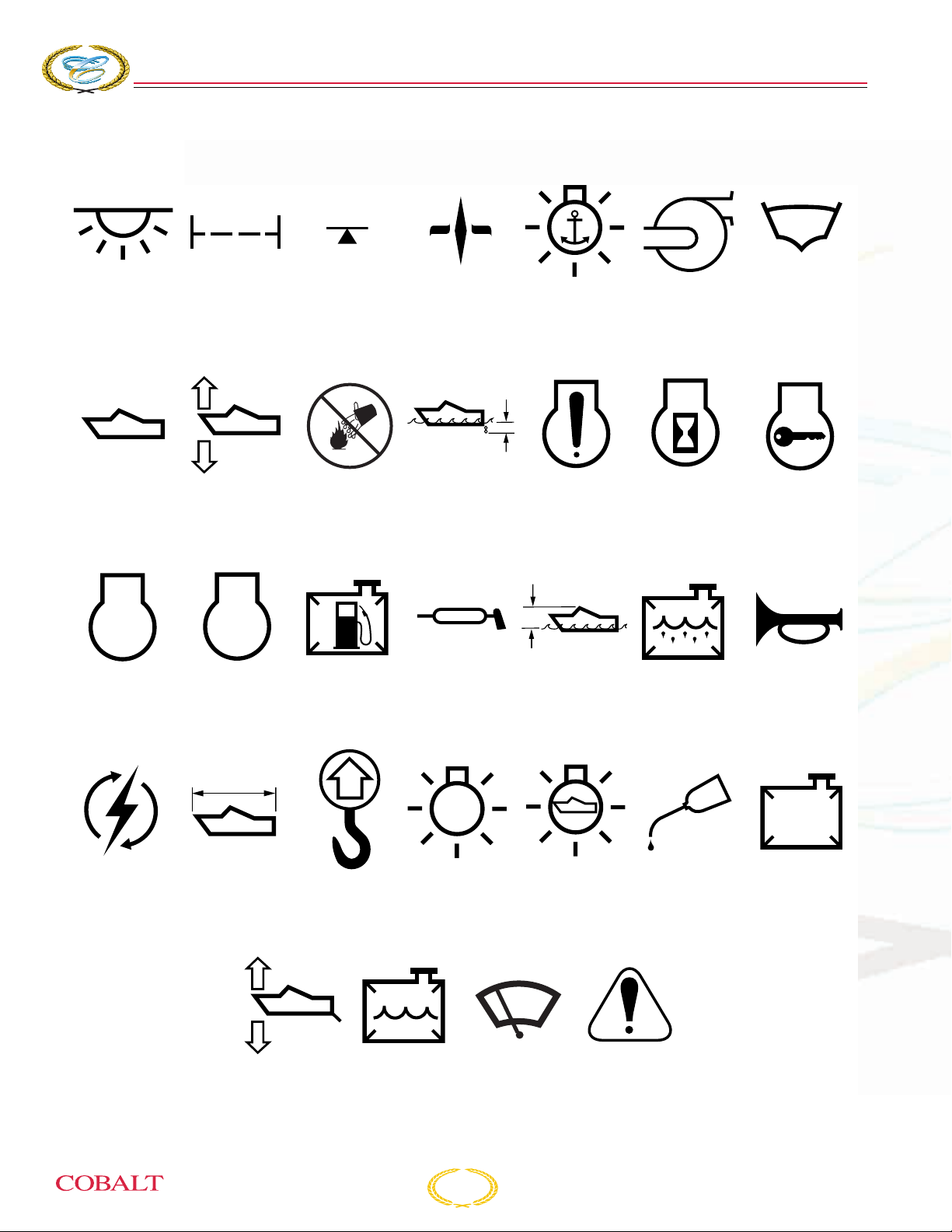
SYMBOLS
276
BOWRIDER
S
ECTION
1
Light Filter Sling Point Compass Anchor
Lights
Boat
Profile
STOP
Engine
Stop
Bow
Tr im
Engine Fuel
Do Not
Use Water
Tank
Draft Engine
Caution
Grease Height
Above Water
Blower Boat
Engine
Hour Meter
Holding
Tank
Engine
Key
Horn
Ignition
Switch
Overall
Length
Tr im
Tabs
Lift
Point
Water
Tank
Light Navigation
Lights
Windshield
Wipers
1-12
Safety Alert
Symbol
Oil Tank
COB_0030_A
276 Owner’s Manual

G
ENERAL
I
NFORMATION
SPECIFICATIONS
Overall Length 27' 6" (8.38 m)
Beam 8' 6" (2.59 m)
Interior Cockpit Width 87" (2.20 m)
Deadrise at Transom 21°
Capacity, Fuel 95 Gal.
Capacity, Fresh Water 10 gal (37.8 L)
Bridge Clearance w/o Bimini 4' 11" (1.50 m)
Bridge Clearance w/Arch 6' 7" (2.02 m)
Draft, Drive Up 27" (0.69 m)
Draft, Drive Down 39" (0.99 m)
Dry Weight 5,500 lbs (2,495 kg)
Boat Certified Capacity Yacht Certified
276 Owner’s Manual
1-13
COBALT
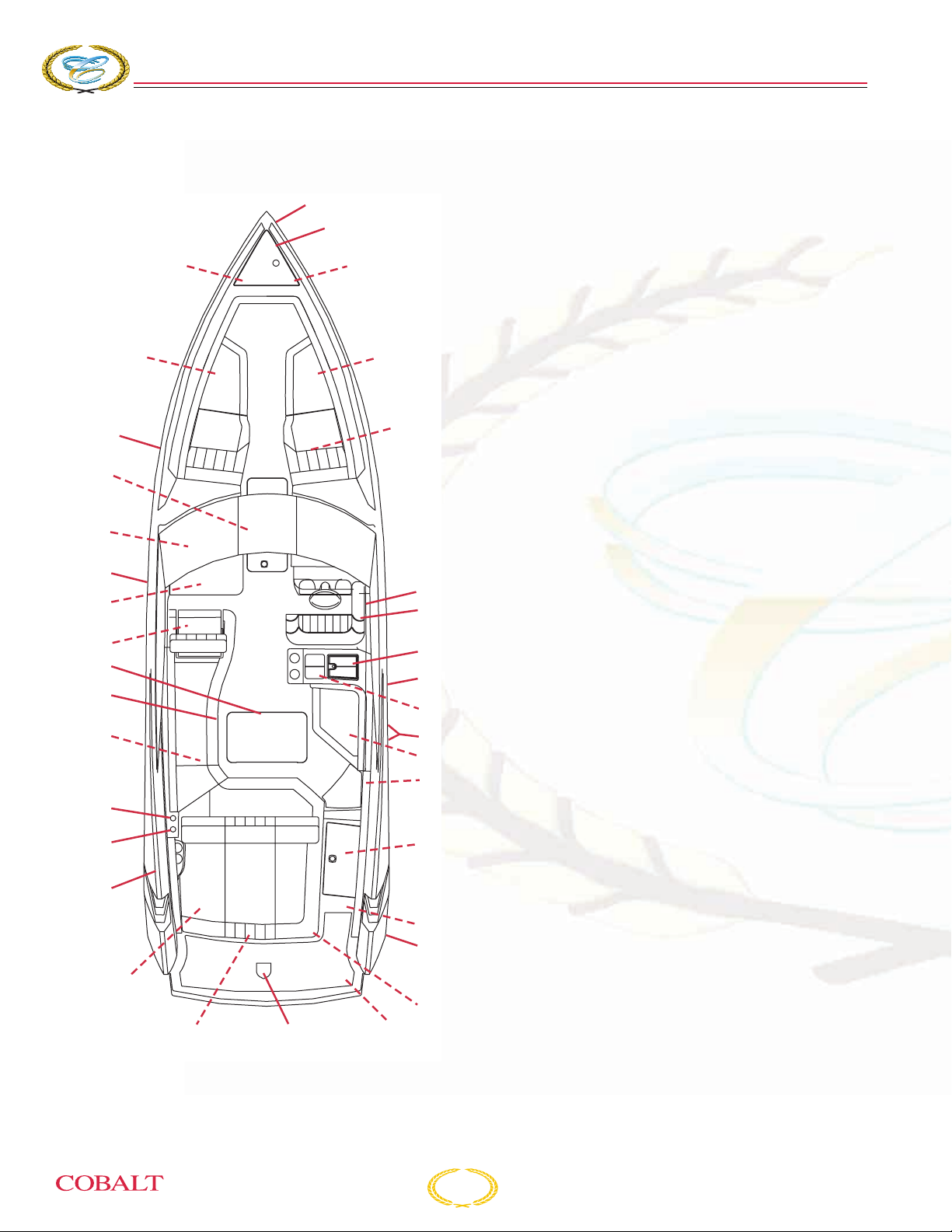
LAYOUT
276
BOWRIDER
S
ECTION
1
29
28
27
26
25
24
23
22
21
30
4
11
31
1
2
3
11
5
6
7
8
9
4
10
11
12
4
1. Docking Lights
2. Anchor Locker
3. Windlass Switch
4. Storage
5. Flag Pole/Dinette Table/Table J-Leg Storage
6. Ignition Safety Switch
7. Circuit Breaker Panel
8. Sink
9. Fuel Fill
10. Fuel Vents
11. Insulated Ice Chest
12. Trash Receptacle
13. Engine Hatch Fluid Reservoir
14. Deck Drain
15. Hour Meter
16. Boarding Ladder
17. Ski Tow Point
18. Aft Bilge Pump/Engine Compartment
19. Trim Unit Pump Fluid Reservoir
20. Water Fill Deck Plate
21. Flagpole Receptacle
22. Anchor Light
23. Battery Switch/Breaker Switch/Air
Compressor/Hand-Held Fire Extinguisher/Ski
Tow Pylon/Jumper Studs
24. Dinette Table Mount
20
19
25. Wet Locker
26. Glove Box/Stereo/12-Volt
13
14
15
1718
16
COB_0283_A
1-14
Receptacle/Accessory Input
27. Optional Waste Drain
28. Head/Control Panel/Waste Level Indicator
29. Cockpit Storage/Anchor Light Storage
30. Head Waste Tank Vent
31. Waste Deck Plate
276 Owner’s Manual

G
ENERAL
PROPELLER APPLICATION CHART
I
NFORMATION
MFGR ENGINE DRIVE PHP
MERC 350 MAG MPI ALPHA 300 MPI 1.47 1.62
MERC 350 MAG MPI BRAVO 1 300 MPI 1.65 1.65
MERC 350 MAG MPI BRAVO 3 300 MPI 2.20 2.43
MERC 377 MPI BRAVO 1 320 MPI 1.65 1.65
MERC 377 MPI BRAVO 3 320 MPI 2.20 2.43 24 pitch 4 Blade 481228 8M8022420
MERC 496 MAG MPI BRAVO 1 375 MPI 1.50 1.65
MERC 496 MAG MPI BRAVO 3 375 MPI 1.81 2.20 24 pitch 4 Blade 481228 8M8022420
MERC 496 MAG HO BRAVO 1X 425 MPI 1.50 1.65
MERC 496 MAG HO BRAVO 3X 425 MPI 1.81 2.20 22.5 pitch 4 Blade 481238 8M8022400
MERC 496 MAG HO BRAVO 1XR 425 MPI 1.50 na
MERC 496 MAG HO BRAVO 3XR 425 MPI 1.81 2.00
MERC 525 EFI BRAVO 1XR 500 MPI 1.50 1.50
MERC 525 EFI BRAVO 3XR 500 MPI 1.81 2.20
MERC 8.2 MAG BRAVO 3 430 MPI 1.81 24 pitch 4 Blade 481228 8M8022420
VOLVO 5.7 Gi SX 300 MPI 1.51 1.51
VOLVO 5.7 Gi DP 300 MPI 1.95 2.14 F3’s 481019 3857584
VOLVO 5.7 GXi SX 320 MPI 1.51 1.51
VOLVO 5.7 GXi DP 320 MPI 1.95 1.95
VOLVO 8.1 Gi DP 375 MPI 1.78 1.78 F5’s 480462 3851495
VOLVO 8.1 GXi DP 420 MPI 1.78 1.78 F5’s 480462 3851495
FUEL
SYSTEM
STD
RATIO
OPT
RATIO
SS PROP SS PART# SS MF G #
24 pitch 3 Blade 481229 8M8022430
24 pitch 3 Blade 481229 8M8022430
22.5 pitch 3 Blade 481239 8M8022410
24 pitch 3 Blade 481229 8M8022430
276 Owner’s Manual
1-15

COBALT
276
BOWRIDER
S
ECTION
1
ALPHABETICAL INDEX
After Boating . . . . . . . . . . . . . . . . . . . . . . . . . . 7-2
After Boating:. . . . . . . . . . . . . . . . . . . . . . . . . . 3-5
After Fueling: . . . . . . . . . . . . . . . . . . . . . . . . . . 3-3
Aids to Navigation . . . . . . . . . . . . . . . . . . . . . 2-22
Air Compressor . . . . . . . . . . . . . . . . . . . . . . . 3-30
Alphabetical Index . . . . . . . . . . . . . . . . . . . . . 1-16
Amenities . . . . . . . . . . . . . . . . . . . . . . . . . . . . . 1-6
Anchor Light. . . . . . . . . . . . . . . . . . . . . . . . . . 3-30
Anchoring. . . . . . . . . . . . . . . . . . . . . . . . . . . . 3-16
Approaching a Mooring . . . . . . . . . . . . . . . . . 3-12
Approaching a Slip. . . . . . . . . . . . . . . . . . . . . 3-12
Audible/Visual Distress Signals . . . . . . . . . . 2-10
Basic Maneuvering . . . . . . . . . . . . . . . . . . . . 3-12
Battery Connections . . . . . . . . . . . . . . . . . . . . 4-9
Battery Switch . . . . . . . . . . . . . . . . . . . . . . . . 3-30
Before Each Use . . . . . . . . . . . . . . . . . . . . . . . 6-2
Before Launching. . . . . . . . . . . . . . . . . . . . . . . 7-1
Before Operating . . . . . . . . . . . . . . . . . . . . . . . 1-5
Before Starting Checklist . . . . . . . . . . . . . . . . . 3-5
Before You Start . . . . . . . . . . . . . . . . . . . . . . . 3-1
Bilge. . . . . . . . . . . . . . . . . . . . . . . . . . . . . . . . . 5-9
Bimini Top - Optional . . . . . . . . . . . . . . . . . . . 3-34
Boarding Ladder . . . . . . . . . . . . . . . . . . . . . . 3-29
Boarding . . . . . . . . . . . . . . . . . . . . . . . . . . . . . 3-4
Boat Information . . . . . . . . . . . . . . . . . . . . . . . 7-6
Boat Theory . . . . . . . . . . . . . . . . . . . . . . . . . . 2-3
Bow Cushion Inserts - Optional . . . . . . . . . . . 3-30
Bow Tonneau Cover - Optional . . . . . . . . . . . 3-33
Break-In . . . . . . . . . . . . . . . . . . . . . . . . . . . . . . 6-2
Burdened Boats. . . . . . . . . . . . . . . . . . . . . . . 2-20
Cabinetry and Wood . . . . . . . . . . . . . . . . . . . . 5-3
Cabinetry . . . . . . . . . . . . . . . . . . . . . . . . . . . . . 5-3
California Air Resource Board (CARB) Label . 2-5
Canvas. . . . . . . . . . . . . . . . . . . . . . . . . . . . . . . 5-7
Capacity. . . . . . . . . . . . . . . . . . . . . . . . . . . . . 2-13
Captain’s Chair Adjustments and Operation . 3-29
Carbon Monoxide Detectors, if equipped . . . . 3-6
Care and Cleaning of Vinyl . . . . . . . . . . . . . . . 5-1
Carpet . . . . . . . . . . . . . . . . . . . . . . . . . . . . . . . 5-4
Casting Off. . . . . . . . . . . . . . . . . . . . . . . . . . . . 7-2
Cedar. . . . . . . . . . . . . . . . . . . . . . . . . . . . . . . . 5-4
Certificate of Limited Warranty . . . . . . . . . . . . 1-2
Certifications . . . . . . . . . . . . . . . . . . . . . . . . . . 1-6
Circuit Breaker Panel. . . . . . . . . . . . . . . . . . . . 4-6
Cleaning Agents . . . . . . . . . . . . . . . . . . . . . . . 2-6
Cleaning Canvas . . . . . . . . . . . . . . . . . . . . . . . 5-7
Cleaning Deck and Hull . . . . . . . . . . . . . . . . . . 5-4
Cleaning Stainless Steel . . . . . . . . . . . . . . . . . 5-5
Clear Vinyl “Isinglass”. . . . . . . . . . . . . . . . . . . . 5-8
Cobalt Check List . . . . . . . . . . . . . . . . . . . . . . . 3-7
Cobalt Instrumentation System . . . . . . . . . . . 3-20
Cockpit Dinette Table - Optional . . . . . . . . . . 3-30
Cockpit Heater - Optional. . . . . . . . . . . . . . . . 3-33
Cockpit Heater . . . . . . . . . . . . . . . . . . . . . . . . . 6-6
Cockpit Tonneau Cover - Optional . . . . . . . . . 3-33
Collisions/Leaks . . . . . . . . . . . . . . . . . . . . . . . . 2-8
Components, Maintenance and Repairs . . . . . 2-7
Construction Standards/Certifications . . . . . . . 1-6
Cooling System . . . . . . . . . . . . . . . . . . . . . . . . 2-4
Corrosion Protection. . . . . . . . . . . . . . . . . . . . . 5-6
CorrosionX . . . . . . . . . . . . . . . . . . . . . . . . . . . . 5-6
Craft Design Category . . . . . . . . . . . . . . . . . . . 1-4
Crossing Situation . . . . . . . . . . . . . . . . . . . . . 2-21
Dark Stowage Areas . . . . . . . . . . . . . . . . . . . . 5-2
Deck and Hull Care . . . . . . . . . . . . . . . . . . . . . 5-4
Deck and Hull. . . . . . . . . . . . . . . . . . . . . . . . . . 5-4
Discharge of Oil . . . . . . . . . . . . . . . . . . . . . . . 2-17
Discharge/Disposal of Waste . . . . . . . . . . . . . . 2-6
Distress Signals . . . . . . . . . . . . . . . . . . . . . . . . 2-9
Docking . . . . . . . . . . . . . . . . . . . . . . . . . . . . . 3-11
Drive Unit Trim . . . . . . . . . . . . . . . . . . . . . . . . 3-13
Drowning . . . . . . . . . . . . . . . . . . . . . . . . . . . . . 2-8
Drugs/Alcohol. . . . . . . . . . . . . . . . . . . . . . . . . 2-14
During Operation . . . . . . . . . . . . . . . . . . . . . . . 7-2
During Operation: . . . . . . . . . . . . . . . . . . . . . . . 3-5
Education Opportunities. . . . . . . . . . . . . . . . . . 2-3
Electric Head Plumbing . . . . . . . . . . . . . . . . . . 4-5
Electrical System . . . . . . . . . . . . . . . . . . . . . . . 4-6
Electrical System . . . . . . . . . . . . . . . . . . . . . . . 6-3
Electrical Systems . . . . . . . . . . . . . . . . . . . . . . 2-4
Electrical Wiring Harness . . . . . . . . . . . . . . . . . 4-2
Electrical. . . . . . . . . . . . . . . . . . . . . . . . . . . . . . 6-8
Electrically Operated Head. . . . . . . . . . . . . . . 3-31
Emergency Considerations . . . . . . . . . . . . . . . 2-7
Emission Control Warranty Information . . . . . . 2-5
Engine . . . . . . . . . . . . . . . . . . . . . . . . . . . . . . . 6-7
Engine/Propulsion/Cooling System . . . . . . . . . 6-3
Entertainment System . . . . . . . . . . . . . . . . . . 3-19
Environmental Considerations . . . . . . . . . . . . . 2-5
Environmental Considerations . . . . . . . . . . . . 3-18
Every 100 Hours. . . . . . . . . . . . . . . . . . . . . . . . 6-3
Every 50 Hours. . . . . . . . . . . . . . . . . . . . . . . . . 6-2
Excessive Noise . . . . . . . . . . . . . . . . . . . . . . . 2-17
Excessive Noise . . . . . . . . . . . . . . . . . . . . . . . . 2-6
Exhaust Emissions. . . . . . . . . . . . . . . . . . . . . . 2-6
Exhaust System . . . . . . . . . . . . . . . . . . . . . . . . 2-4
Extended Service Agreement. . . . . . . . . . . . . . 1-5
Features/Construction . . . . . . . . . . . . . . . . . . . 1-6
1-16
276 Owner’s Manual

G
ENERAL
I
NFORMATION
Federal, State and Local Regulations . . . . . . 2-17
Fire Extinguisher . . . . . . . . . . . . . . . . . . . . . . . 2-2
Fire Suppression Equipment . . . . . . . . . . . . . . 4-6
Fire. . . . . . . . . . . . . . . . . . . . . . . . . . . . . . . . . . 2-7
Fire/Explosion . . . . . . . . . . . . . . . . . . . . . . . . . 3-1
First-Time Operation . . . . . . . . . . . . . . . . . . . . 3-1
Fishery Resources . . . . . . . . . . . . . . . . . . . . . . 2-6
Float Plan. . . . . . . . . . . . . . . . . . . . . . . . . . . . . 7-5
Flooding/Swamping . . . . . . . . . . . . . . . . . . . . . 2-8
Foreign Species. . . . . . . . . . . . . . . . . . . . . . . . 2-7
Freezing Temperatures . . . . . . . . . . . . . . . . . 3-18
Fresh Water . . . . . . . . . . . . . . . . . . . . . . . . . . . 4-4
Fresh Water . . . . . . . . . . . . . . . . . . . . . . . . . . . 6-4
Fuel Log. . . . . . . . . . . . . . . . . . . . . . . . . . . . . . 7-4
Fuel Requirements . . . . . . . . . . . . . . . . . . . . . 3-2
Fuel Routing . . . . . . . . . . . . . . . . . . . . . . . . . . 4-3
Fuel System. . . . . . . . . . . . . . . . . . . . . . . . . . . 2-3
Fuel System. . . . . . . . . . . . . . . . . . . . . . . . . . . 6-4
Fuel . . . . . . . . . . . . . . . . . . . . . . . . . . . . . . . . . 3-2
Fuel/Spillage . . . . . . . . . . . . . . . . . . . . . . . . . . 2-5
Fueling . . . . . . . . . . . . . . . . . . . . . . . . . . . . . . . 3-2
Fuses . . . . . . . . . . . . . . . . . . . . . . . . . . . . . . . . 4-7
Galvanic Corrosion . . . . . . . . . . . . . . . . . . . . . 5-6
General Safety. . . . . . . . . . . . . . . . . . . . . . . . 2-12
Getting Underway . . . . . . . . . . . . . . . . . . . . . . 3-5
Gray Water . . . . . . . . . . . . . . . . . . . . . . . . . . . 6-4
Grounding . . . . . . . . . . . . . . . . . . . . . . . . . . . . 2-8
Handholds . . . . . . . . . . . . . . . . . . . . . . . . . . . 2-13
Handling Dock and Mooring Lines. . . . . . . . . . 3-6
Helm and Instrumentation . . . . . . . . . . . . . . . 3-21
High-Speed Operation. . . . . . . . . . . . . . . . . . 3-15
Horn or Whistle . . . . . . . . . . . . . . . . . . . . . . . . 2-2
If You Sell Your Cobalt Boat . . . . . . . . . . . . . . 1-5
INSHORE – Category C . . . . . . . . . . . . . . . . . 1-5
Inside the Bulkhead . . . . . . . . . . . . . . . . . . . . . 5-6
Instructions . . . . . . . . . . . . . . . . . . . . . . . . . . 3-31
Insurance . . . . . . . . . . . . . . . . . . . . . . . . . . . . 2-3
Intended Use . . . . . . . . . . . . . . . . . . . . . . . . . . 1-4
Introduction . . . . . . . . . . . . . . . . . . . . . . . . . . . 1-4
Introduction . . . . . . . . . . . . . . . . . . . . . . . . . . . 4-1
Isolated Danger Markers . . . . . . . . . . . . . . . . 2-26
Jump Start Studs . . . . . . . . . . . . . . . . . . . . . . . 4-9
Lateral Markers . . . . . . . . . . . . . . . . . . . . . . . 2-24
Launching Checklist. . . . . . . . . . . . . . . . . . . . . 3-4
Launching . . . . . . . . . . . . . . . . . . . . . . . . . . . . 3-4
Layout . . . . . . . . . . . . . . . . . . . . . . . . . . . . . . 1-14
Leather Care . . . . . . . . . . . . . . . . . . . . . . . . . . 5-2
Leaving . . . . . . . . . . . . . . . . . . . . . . . . . . . . . 3-10
Life Raft . . . . . . . . . . . . . . . . . . . . . . . . . . . . . 2-11
Lifesaving Devices . . . . . . . . . . . . . . . . . . . . . . 2-2
Lifesaving Equipment . . . . . . . . . . . . . . . . . . . . 2-9
Lifting the Boat . . . . . . . . . . . . . . . . . . . . . . . . . 6-4
Light Structures . . . . . . . . . . . . . . . . . . . . . . . 2-26
Lighthouses . . . . . . . . . . . . . . . . . . . . . . . . . . 2-27
Lighting/Bulb Replacement . . . . . . . . . . . . . . . 4-8
Load Distribution . . . . . . . . . . . . . . . . . . . . . . 3-13
Loading. . . . . . . . . . . . . . . . . . . . . . . . . . . . . . 2-13
Loading. . . . . . . . . . . . . . . . . . . . . . . . . . . . . . . 3-4
Lowering . . . . . . . . . . . . . . . . . . . . . . . . . . . . . 3-17
Lubrication System. . . . . . . . . . . . . . . . . . . . . . 2-4
Macerator Pump . . . . . . . . . . . . . . . . . . . . . . . 3-32
Maintenance Schedule. . . . . . . . . . . . . . . . . . . 6-1
Manually Operated Head . . . . . . . . . . . . . . . . 3-31
Marine Growth . . . . . . . . . . . . . . . . . . . . . . . . . 5-9
Marine Sanitation . . . . . . . . . . . . . . . . . . . . . . 2-17
Marine Toilet (Head) and Macerator -
Optional . . . . . . . . . . . . . . . . . . . . . . . . . . . . . 3-31
MARPOL Treaty . . . . . . . . . . . . . . . . . . . . . . . . 2-5
Medical Emergency . . . . . . . . . . . . . . . . . . . . . 2-8
Meeting Head-On . . . . . . . . . . . . . . . . . . . . . . 2-21
MerCruiser . . . . . . . . . . . . . . . . . . . . . . . . . . . . 1-6
Minor Lights . . . . . . . . . . . . . . . . . . . . . . . . . . 2-26
Monthly . . . . . . . . . . . . . . . . . . . . . . . . . . . . . . . 6-3
Mooring Buoys . . . . . . . . . . . . . . . . . . . . . . . . 2-23
Motor Box Assembly . . . . . . . . . . . . . . . . . . . 3-36
Nautical Terms . . . . . . . . . . . . . . . . . . . . . . . . . 1-9
Navigation . . . . . . . . . . . . . . . . . . . . . . . . . . . 2-20
Navigation Lights . . . . . . . . . . . . . . . . . . . . . . . 2-2
NMMA . . . . . . . . . . . . . . . . . . . . . . . . . . . . . . . 1-6
OCEAN – Category A. . . . . . . . . . . . . . . . . . . . 1-4
OFFSHORE – Category B . . . . . . . . . . . . . . . . 1-5
On the Water . . . . . . . . . . . . . . . . . . . . . . . . . . 3-4
Operating Conditions . . . . . . . . . . . . . . . . . . . 2-13
Operation Checklist . . . . . . . . . . . . . . . . . . . . . 2-4
Operation Failure . . . . . . . . . . . . . . . . . . . . . . . 2-8
Operation Quick Reference . . . . . . . . . . . . . . . 7-1
Optional Equipment . . . . . . . . . . . . . . . . . . . . 3-28
Other Areas . . . . . . . . . . . . . . . . . . . . . . . . . . . 5-6
Other Canvas Components . . . . . . . . . . . . . . . 5-8
Overtaking . . . . . . . . . . . . . . . . . . . . . . . . . . . 2-22
Owner Responsibility/Warranty Procedure . . . 1-5
Owner/Operator Responsibilities . . . . . . . . . . . 2-1
Paints . . . . . . . . . . . . . . . . . . . . . . . . . . . . . . . . 2-6
Passengers . . . . . . . . . . . . . . . . . . . . . . . . . . 2-15
Personal Flotation Devices. . . . . . . . . . . . . . . . 2-9
Platform Dragging (“Teak Surfing”) . . . . . . . . 2-19
Plumbing . . . . . . . . . . . . . . . . . . . . . . . . . . . . . 6-8
Precautions . . . . . . . . . . . . . . . . . . . . . . . . . . . 3-1
Pre-Operation. . . . . . . . . . . . . . . . . . . . . . . . . . 7-1
Pre-Operation: . . . . . . . . . . . . . . . . . . . . . . . . . 3-5
276 Owner’s Manual
1-17

COBALT
276
BOWRIDER
S
ECTION
1
Preventive Steps . . . . . . . . . . . . . . . . . . . . . . . 5-5
Privileged Boats. . . . . . . . . . . . . . . . . . . . . . . 2-20
Propeller Application Chart . . . . . . . . . . . . . . 1-15
Proposition 65 . . . . . . . . . . . . . . . . . . . . . . . . . 2-6
Publications . . . . . . . . . . . . . . . . . . . . . . . . . . . 1-9
Qualified Boat Operators . . . . . . . . . . . . . . . . 2-17
Quarterly . . . . . . . . . . . . . . . . . . . . . . . . . . . . . 6-3
Radar Reflectors . . . . . . . . . . . . . . . . . . . . . . 2-11
Radio Communication . . . . . . . . . . . . . . . . . . . 2-9
Range Lights . . . . . . . . . . . . . . . . . . . . . . . . . 2-27
Reactivating the Boat After Storage . . . . . . . . 6-5
Recommended Cleaning Solutions for
PreFixx-Coated Nautolex Vinyls . . . . . . . . . . . 5-2
Recommended Safety Equipment. . . . . . . . . . 2-2
Recommended Spare Parts . . . . . . . . . . . . . . 2-3
Registration/Documentation . . . . . . . . . . . . . . 2-1
Regulatory Markers . . . . . . . . . . . . . . . . . . . . 2-23
Remote Control System. . . . . . . . . . . . . . . . . . 2-3
Rendering Assistance . . . . . . . . . . . . . . . . . . 2-18
Reporting Accidents. . . . . . . . . . . . . . . . . . . . 2-18
Required Safety Equipment. . . . . . . . . . . . . . . 2-2
Returning to Port . . . . . . . . . . . . . . . . . . . . . . . 7-2
Returning . . . . . . . . . . . . . . . . . . . . . . . . . . . . 3-10
Rosewood Dash . . . . . . . . . . . . . . . . . . . . . . . 5-3
Rules of the Road/Sound Signals . . . . . . . . . 2-20
Safety Alert From August 28, 2001:. . . . . . . . 2-20
Safety While Boating . . . . . . . . . . . . . . . . . . . 2-17
Safety. . . . . . . . . . . . . . . . . . . . . . . . . . . . . . . 2-12
Salt Water . . . . . . . . . . . . . . . . . . . . . . . . . . . 3-18
Salt Water . . . . . . . . . . . . . . . . . . . . . . . . . . . . 5-7
Scheduled Maintenance and Service . . . . . . . 6-1
Sea Anchors . . . . . . . . . . . . . . . . . . . . . . . . . 2-11
Seating. . . . . . . . . . . . . . . . . . . . . . . . . . . . . . 2-12
Seaworthiness Inspection . . . . . . . . . . . . . . . . 2-4
Serial Number Locations . . . . . . . . . . . . . . . . . 1-6
Service Log . . . . . . . . . . . . . . . . . . . . . . . . . . . 7-3
Setting . . . . . . . . . . . . . . . . . . . . . . . . . . . . . . 3-17
SHELTERED WATERS – Category D. . . . . . . 1-5
Shifting/Running . . . . . . . . . . . . . . . . . . . . . . . 3-8
Shipshape . . . . . . . . . . . . . . . . . . . . . . . . . . . . 3-4
Signal Words/Definitions . . . . . . . . . . . . . . . . 2-12
Sisal Seagrass Carpet Alternative Cleaning
Instructions . . . . . . . . . . . . . . . . . . . . . . . . . . . 5-3
Ski Tow Pylon - Removable. . . . . . . . . . . . . . 3-34
Skill/Experience . . . . . . . . . . . . . . . . . . . . . . . 2-14
Snap Fasteners . . . . . . . . . . . . . . . . . . . . . . . . 5-9
Solid Waste Disposal. . . . . . . . . . . . . . . . . . . 2-17
Special Cleaning Problems . . . . . . . . . . . . . . . 5-1
Special Cleaning Problems . . . . . . . . . . . . . . . 5-8
Special Situations . . . . . . . . . . . . . . . . . . . . . 2-22
Specifications . . . . . . . . . . . . . . . . . . . . . . . . . 1-13
SS Arch with Bimini Instructions - Optional . . 3-34
Stainless Steel and Chrome. . . . . . . . . . . . . . . 5-5
Standard Equipment. . . . . . . . . . . . . . . . . . . . 3-27
Starting Engines . . . . . . . . . . . . . . . . . . . . . . . . 7-2
Starting the Engine. . . . . . . . . . . . . . . . . . . . . . 3-7
Starting/Shifting/Steering/Stopping . . . . . . . . . 3-6
Steering System . . . . . . . . . . . . . . . . . . . . . . . . 2-3
Steering . . . . . . . . . . . . . . . . . . . . . . . . . . . . . . 3-8
Step 1 Cleaners . . . . . . . . . . . . . . . . . . . . . . . . 5-1
Step 2 Cleaners . . . . . . . . . . . . . . . . . . . . . . . . 5-1
Step 3 Cleaners . . . . . . . . . . . . . . . . . . . . . . . . 5-2
Stopping the Engine. . . . . . . . . . . . . . . . . . . . 3-10
Stopping the Engines . . . . . . . . . . . . . . . . . . . . 7-2
Storage Cradle . . . . . . . . . . . . . . . . . . . . . . . . . 6-4
Storage/Winterization. . . . . . . . . . . . . . . . . . . . 6-5
Storms . . . . . . . . . . . . . . . . . . . . . . . . . . . . . . . 2-8
Symbols . . . . . . . . . . . . . . . . . . . . . . . . . . . . . 1-12
Teak Swim Platform . . . . . . . . . . . . . . . . . . . . . 5-4
Techniques. . . . . . . . . . . . . . . . . . . . . . . . . . . 3-12
Tie-Down Locations . . . . . . . . . . . . . . . . . . . . 3-35
Tool Kit - Optional. . . . . . . . . . . . . . . . . . . . . . 3-36
Topside. . . . . . . . . . . . . . . . . . . . . . . . . . . . . . . 5-6
Towing . . . . . . . . . . . . . . . . . . . . . . . . . . . . . . 3-17
Transom Tilt Switch - Optional . . . . . . . . . . . . 3-35
Trim Tabs . . . . . . . . . . . . . . . . . . . . . . . . . . . . 3-14
Trim . . . . . . . . . . . . . . . . . . . . . . . . . . . . . . . . 3-13
Troubleshooting . . . . . . . . . . . . . . . . . . . . . . . . 6-6
Types of Buoys. . . . . . . . . . . . . . . . . . . . . . . . 2-22
Unscheduled Maintenance. . . . . . . . . . . . . . . . 6-3
Using Lifting Slings. . . . . . . . . . . . . . . . . . . . . . 6-4
Ventilation System . . . . . . . . . . . . . . . . . . . . . . 2-3
Ventilation. . . . . . . . . . . . . . . . . . . . . . . . . . . . 2-15
Vinyl Interior and Upholstery . . . . . . . . . . . . . . 5-1
Visibility . . . . . . . . . . . . . . . . . . . . . . . . . . . . . 2-14
Visual Distress Signals. . . . . . . . . . . . . . . . . . . 2-2
Volvo Penta Ocean Series Outdrive. . . . . . . . 3-29
Volvo Penta . . . . . . . . . . . . . . . . . . . . . . . . . . . 1-6
Wake/Wash . . . . . . . . . . . . . . . . . . . . . . . . . . 2-18
Wake/Wash . . . . . . . . . . . . . . . . . . . . . . . . . . . 2-6
Warning Labels . . . . . . . . . . . . . . . . . . . . . . . . 1-7
Warning Markers . . . . . . . . . . . . . . . . . . . . . . 2-28
Warranty Service Requirements . . . . . . . . . . . 1-5
Warranty Transfer Form . . . . . . . . . . . . . . . . . . 7-7
Waste Disposal . . . . . . . . . . . . . . . . . . . . . . . 3-32
Water Rescue (Man Overboard) . . . . . . . . . . . 2-8
Water Sports Safety . . . . . . . . . . . . . . . . . . . . 2-18
Water System (if equipped) . . . . . . . . . . . . . . . 6-4
Water System. . . . . . . . . . . . . . . . . . . . . . . . . 3-31
Water System. . . . . . . . . . . . . . . . . . . . . . . . . . 4-6
1-18
276 Owner’s Manual

G
Water/Plumbing . . . . . . . . . . . . . . . . . . . . . . . . 4-4
Waterfall Bubinga or Birdseye Maple Dash. . . 5-3
Weather/Seas . . . . . . . . . . . . . . . . . . . . . . . . 2-13
Weighing . . . . . . . . . . . . . . . . . . . . . . . . . . . . 3-17
Welcome . . . . . . . . . . . . . . . . . . . . . . . . . . . . . 1-1
When Fueling: . . . . . . . . . . . . . . . . . . . . . . . . . 3-3
Whistle/Horn Signals . . . . . . . . . . . . . . . . . . . 2-20
Windshield Hook . . . . . . . . . . . . . . . . . . . . . . 3-29
Windshield . . . . . . . . . . . . . . . . . . . . . . . . . . . . 5-9
Zippers. . . . . . . . . . . . . . . . . . . . . . . . . . . . . . . 5-8
ENERAL
I
NFORMATION
276 Owner’s Manual
1-19

NOTES
COBALT
276
BOWRIDER
S
ECTION
1
1-20
276 Owner’s Manual

276 Owner’s Manual
R
ESPONSIBILITIES
S
AFETY
S
ECTION
AND
2
Your safety, the safety of your passengers, and
other boaters are among your responsibilities as
operator of this boat. Your boat must be in
compliance with U.S. Coast Guard (USCG) safety
equipment regulations. You should know how to
react correctly to adverse weather conditions, have
good navigation skills and follow the “Rules of the
Road” as defined by the USCG and
state/county/local regulations.
OWNER/OPERATOR
RESPONSIBILITIES
At the time of delivery, the owner/operator is
responsible for:
• Understanding warranty terms and conditions
of both the propulsion unit(s) and boat.
• Obtaining insurance.
• Examining boat to ensure proper operation of
all systems.
Before operating the boat, the owner/operator is
responsible for:
• Obtaining state registration of the boat.
• Providing the proper USCG required safety
equipment.
• Following proper break-in procedure for the
propulsion units.
While operating the boat, the owner/operator is
responsible for:
• Knowing that all safety equipment and
personal flotation devices are in good condition
and suitable for your boat and passenger load.
• Having at least one other passenger who is
capable of handling the boat in an emergency.
• Following safe operating practices and the
rules of the road.
• Understanding proper maintenance and
knowledge of the boat’s operating systems.
• Providing safety training for the passengers.
• Avoiding use of alcohol and other drugs.
• Providing assistance to other boaters.
Registration/Documentation
The USCG requires that all power boats operated
on the navigable waters of the U.S. must be
registered in the state of main use; also, many
states require registration in that state whenever
boating on waters within their state boundary.
Contact your state boating authorities (and
neighboring states) for registration information on
boats and trailers.
Your authorized Cobalt dealer can supply you with
the appropriate forms.
• Understanding safety information and proper
operating procedures within this manual.
276 Owner’s Manual
2-1

COBALT
276
BOWRIDER
S
ECTION
2
Required Safety Equipment
The Federal Boat Safety Act of 1971 (FBSA/71)
established minimum safety standards for boats
and associated equipment, specified by the USCG.
In addition, the ABYC and the NMMA work with
boat builders to develop voluntary standards that
exceed base requirements.
The included safety equipment on your Cobalt boat
meets or exceeds the standards of the USCG,
ABYC and the NMMA. Some required safety
equipment such as personal flotation devices are
not included with your Cobalt boat. Your authorized
Cobalt dealer can help you choose the appropriate
equipment.
NOTICE: Many states’
equipment requirements go
beyond USCG requirements.
Contact your state boating office
for further information.
Equipment requirements for
coastal and inland waters differ.
Check with local authorities or
the USCG for further information
about coastal water
requirements.
Navigation Lights
All power boats underway between sunset and
sunrise must display proper navigation lights. All
boats at anchor must display a proper anchor light.
Anchor light must be visible 360 degrees. Your
Cobalt boat is equipped with international
navigation lights.
Horn or Whistle
All boats over 16 ft (4.8 m) in length must be
equipped with an operable horn or whistle, audible
from one mile. Your Cobalt boat is equipped with a
USCG approved horn.
Fire Extinguisher
All inboard/outboard boats must carry an
appropriate portable marine type fire extinguisher
in operable condition and accessible location. Your
Cobalt boat is equipped with a portable fire
extinguisher and may have a fixed system fire
extinguisher.
Lifesaving Devices
All boats must carry one USCG approved Type I, II
or III, wearable, personal flotation device, of the
proper size, for each person onboard. All boats
over 16 ft (4.8 m) in length must carry one USCG
approved Type IV throwable lifesaving device, such
as a ring buoy or buoyant cushion. To meet
requirements, each lifesaving device must have a
currently legible USCG approval stamp
permanently affixed. Your authorized Cobalt dealer
can help you select appropriate PFDs and
throwable lifesaving devices for your area.
Visual Distress Signals
All boats over 16 ft (4.8 m) must have onboard day
and night visual distress signals. Your authorized
Cobalt dealer can help you select appropriate
visual distress signals for your area.
Recommended Safety Equipment
In spite of all efforts to the contrary, problems or
mishaps sometimes occur while boating. Stock
these items listed below on your boat to help make
unexpected events more manageable.
• Anchor and anchor line
• Compass
• First aid kit
• Distress signals (flag for daytime, flares for
darkness)
• Flashlight and spare batteries
• Portable radio
• Cellular phone
• Sea anchor
• Binoculars
• Emergency Position Indicating Radio Beacon
(EPIRB)
• Boat hook
• Sun glasses and sun block lotion
2-2
276 Owner’s Manual

R
ESPONSIBILITIES AND
S
AFETY
Recommended Spare Parts
The following list contains common spare parts you
should carry onboard. Review all the equipment on
your boat. Be sure to have spare parts available to
maintain and make minor repairs if necessary.
Refer to all operator’s manuals in your owner’s
packet for the manufacturer’s recommended spare
parts.
• Lanyard for ignition safety switch
• Engine and generator oil
• Hydraulic fluid for the steering system and trim
system
• Ignition keys
• Tape, tie straps and rope
• Light bulbs and fuses
• Propeller with attaching hardware
Education Opportunities
Be boat smart from the start, take a boating safety
course and get a free vessel safety check annually
for your boat. For more information, contact: United
States Coast Guard Auxiliary, www.cgaux.org;
United States Power Squadrons, 888-FOR-USPS,
www.usps.org. Most boaters can enhance their
enjoyment of boating experiences through
increased knowledge of safe operation, navigation
and regulation of pleasure boats. The following is a
list of some other agencies and organizations that
offer Water Safety, First Aid and CPR courses or
information.
Insurance
You must get insurance before operating your new
boat. Insurance for loss by fire, theft or other
causes, or liability protection against accidents is a
must for responsible boaters. The boat owner is
legally responsible for any damage or injury caused
when he, or someone else operating the boat, is
involved in an accident. Many states have laws
detailing minimum insurance needs. Your insurance
agent or your dealer may be able to supply you with
more information.
BOAT THEORY
The following information briefly explains main
system theory.
Remote Control System
The shift levers and throttle levers are connected to
the engine and propulsion units by mechanical
push/pull cables. The shift lever controls the
direction of the boat, and the throttle lever controls
the speed of the boat.
Steering System
The steering wheel (helm) is connected to a
hydraulic cylinder. As you turn the helm, hydraulic
fluid directs movement of a steering cylinder. The
cylinder is mechanically connected to the drive
units. In an emergency the drive units can be
turned manually by connecting a line to the drive
unit and directing them.
To find boating safety courses in your area, call
your state’s local boating agency or the USCG
boating safety course line at 800-336-2628
(800-245-2628 in Virginia).
• American Red Cross
• U.S. Coast Guard Auxiliary
• U.S. Power Squadrons
• State Boating Offices
• Canadian Power and Sail Squadrons
• Yacht Clubs
276 Owner’s Manual
Fuel System
The fuel system consists of a permanent tank with
an air vent system, fuel level sensor and fuel fill
components. The tank has an anti-siphon valve to
prevent fuel from accumulating in the bilge if a hose
should break.
Ventilation System
The engine compartment ventilation system
consists of switch operated blowers installed within
the engine compartment. When activated, the
blowers exhaust dangerous fumes and intake fresh
air through vents. Operate the blowers for at least
four minutes before starting the engines.
2-3

COBALT
276
BOWRIDER
S
ECTION
2
Electrical Systems
Your Cobalt boat can be equipped with one or two
electrical systems. A direct current (DC) system is
battery powered and supplies electricity to lights,
pumps, blowers, engine ignition and sometimes a
refrigerator. An alternating current (AC) system is
shore power, or generator, and supplies electricity
to the electrical outlet, air conditioning, battery
charger and other 110V AC or 220V AC appliances
or components.
Cooling System
The engines and generator, if equipped, are cooled
by the continuous intake of raw water through
independent water intakes. The water flows to
water pumps on the engines and/or generator for
circulation around internal components. The engine
water intakes and outlets are located in the drive
units. A generator water intake is in the bottom of
the hull and the exhaust is usually on the side of the
boat, above the waterline. If your boat is equipped
with an air conditioner, the air conditioner water
intake is in the bottom of the hull and exits from the
side. Your Cobalt boat may be equipped with a
self-contained cooling system that pumps a mixture
of fresh water and antifreeze through a large heat
exchanger to reduce temperatures. Raw water is
circulated through the other side of the heat
exchanger to dissipate heat absorbed by the
coolant mixture.
Exhaust System
The engine and generator exhaust systems, if
equipped, remove the gases produced by the
running engine and vents them away from the boat.
Engine exhaust is usually vented through the drive
unit propeller but may be diverted through the
transom with the optional captain’s call exhaust
system. Engine and generator cooling water are
also removed along with the exhaust gases.
Lubrication System
The engines and generator, if equipped, use a
pressurized continuous loop lubrication system that
must be periodically serviced in accordance with
the manufacturer’s recommendations. The engines
have electrical transducer units to provide oil
pressure signals to gauges at the helm. Full oil
pressure must be available for proper lubrication,
so monitoring the gauges is important, especially
when operating at cruising speeds and above.
Seaworthiness Inspection
The following checks are essential to safe boating
and must be performed before starting the engines.
Get into the habit of performing these checks in the
same order each time so that it becomes routine.
• Check the weather report, wind and water
conditions.
• Check that required safety equipment is
onboard.
• Check that fire extinguisher(s) is fully charged.
• Check that bilge drain plug is properly installed.
• Check that no fuel, oil or water is leaking or has
leaked into the bilge compartment.
• Check all hoses and connections for leakage
and damage.
• Check that all batteries are fully charged and
have the proper level.
• Check electrical circuits (lights, pumps, horn,
etc.) for proper operation.
• Check that steering system operates properly.
• Be sure the boat is not overloaded.
• Check that all maintenance has been
performed.
Operation Checklist
While operating your boat, frequently check that the
control and steering systems continue to operate
smoothly. Monitor your gauges for signs of
abnormal behavior. Beware of any excessive
vibration. Refer to Section 3, Before Starting
Checklist.
2-4
276 Owner’s Manual

R
ESPONSIBILITIES AND
S
AFETY
A WARNING
Avoid the risk of creating a hazardous
situation. DO NOT operate the boat if
any problem is found during this
inspection.
Problems found during this inspection should be
handled by your authorized Cobalt dealer.
Environmental Considerations
As a boater, you already appreciate nature’s beauty
and the peace of the great outdoors. It is a boater’s
responsibility to protect the natural environment by
keeping waterways clean.
MARPOL Treaty
The USCG enforces the International Convention
for the Prevention of Pollution from ships,
commonly referred to as the MARPOL Treaty
(MARine POLlution). This treaty prohibits the
overboard dumping of all ship-generated plastics,
chemicals, garbage and oil.
A DANGER
Avoid fire or explosion. Fumes from rags
can collect in bilge and be extremely
hazardous. DO NOT store rags used to
wipe up fuel or solvent spills in the boat.
Dispose of rags properly ashore.
Emission Control Warranty Information
The engine in your Cobalt boat
meets the strict requirements
set forth by CARB. The engine
has a special environmental
COB_0016_A
label are required by CARB. The label has 1, 2, 3 or
4 stars. The label MUST be affixed to the boat, if
the boat is operated in the state of California and/or
bordering waters.
tag and the boat has this label
affixed to it. The tag and the
Fuel/Spillage
The spilling of fuel or oil into our waterways
contaminates the environment and is dangerous to
wildlife. Do not discharge or dispose of fuel or oil
into the water; it is prohibited and you can be fined.
These are two common, accidental types of
discharge:
• Overfilling the fuel tanks
• Pumping contaminated bilge water
California Air Resource Board (CARB) Label
Your boat may have an environmental star label
affixed on the bow, port side of the boat as part of
the California Air Resource Board (CARB) SD/I
rule. This label must stay affixed to the boat if it is
operated in California. The label identifies your boat
is equipped with a California Certified Engine. The
label is positioned so it will be at the leading or
trailing edge of the state registration numbers.
276 Owner’s Manual
2-5

COBALT
276
BOWRIDER
S
ECTION
2
Proposition 65
A WARNING
A wide variety of components used on
this vessel contain or emit chemicals
known to the state of California to cause
cancer, birth defects and other
reproductive harm.
EXAMPLES INCLUDE:
• Engine and generator exhaust
• Engine and generator fuel, and other
liquids such as coolants and oil,
especially used motor oil
• Cooking fuels
• Cleaners, paints and substances used
for vessel repair
• Waste materials that result from wear
of vessel components
• Lead from battery terminals and from
other sources such as ballast or
fishing sinkers
TO AVOID HARM:
• Keep away from engine, generator and
cooking fuel exhaust fumes.
Excessive Noise
Noise means engine noise, radio noise or even
voices. Many bodies of water have adopted noise
limits. Do not use thru-transom exhaust unless you
are well offshore. Music and loud conversation can
carry a considerable distance on water, especially
at night.
Wake/Wash
Be alert for NO WAKE zones. You may be
responsible for any damage or injury caused by
your wake/wash. Prior to entering a no wake zone,
come off plane to the slowest steerable speed.
Exhaust Emissions
Increased exhaust (hydrocarbon) emissions pollute
our water and air. Keep your engine tuned and boat
hull clean for peak performance. Consult your
authorized Cobalt dealer and propulsion unit
operator’s manual for information.
Paints
If your boat is kept in water where marine growth is
a problem, the use of anti-fouling paint may reduce
the growth rate. Be aware of environmental
regulations that may govern your paint choice.
Contact your local boating authorities for
information.
• Wash areas thoroughly with soap and
water after handling the substances
above.
Discharge/Disposal of Waste
Waste means all forms of garbage, plastics,
recyclables, food, wood, detergents, sewage and
even fish parts in certain waters - in short, nearly
everything. We recommend you bring back
everything you take out with you for proper disposal
ashore. Use an approved pump-out facility at your
marina. Many areas prohibit the discharge of
sewage overboard or even an operable overboard
waste discharge.
Cleaning Agents
Household cleaners should be used sparingly and
not discharged into waterways. Do not mix cleaners
and be sure to use plenty of ventilation in enclosed
areas. DO NOT use products which contain
phosphates, chlorine, solvents, nonbiodegradable
or petroleum based products. Citrus-based
cleaners are excellent for marine cleaning
purposes and are safe for you and the environment.
Do not use citrus-based cleaners on stainless steel.
Fishery Resources
There is a tremendous drain on our fishery
resources. Over-fishing and pollution have strained
the fish population. Do your part by keeping only
what you will eat and practice catch-and-release.
2-6
276 Owner’s Manual

R
ESPONSIBILITIES AND
S
AFETY
Foreign Species
If you trailer your Cobalt boat from lake to lake, you
may unknowingly introduce a foreign aquatic
species from one lake to the next. Thoroughly clean
the boat below the waterline, remove all weeds and
algae, and drain the bilge before launching the boat
in a new body of water.
Components, Maintenance and Repairs
Only your authorized Cobalt dealer should make
any alterations, modifications or repairs that could
affect safety, design integrity or warranty coverage.
Included with your owner’s packet are your
propulsion unit manuals. These manuals were
prepared by the manufacturer and contain
information concerning the operation and care of
your engine and drive unit. Please read these
manuals thoroughly and become acquainted with
this information.
It is advisable to maintain a service log to record
service checks, such as oil changes, so you can
determine when it is time for servicing. A
maintenance log is helpful when requesting
warranty service using the extended warranty
coverage. Be sure to collect receipts for work
performed and make an entry in the Service Log in
the back of this manual.
Emergency Considerations
Be prepared to deal with emergencies before they
happen. Try to formulate a plan for each type in
advance so that decisions can be made quickly and
without hesitation. Precious moments lost can
mean the difference between losing and saving a
life.
Fire
You must be prepared and act quickly when dealing
with a fire. It is not recommended to battle a fire for
an extended period of time. Turn engines off and
abandon the boat if the fire cannot be extinguished
quickly. Swim at least 25 yards (23 meters) upwind
from the boat and use the visual distress signals to
get assistance. Onboard fires involving the fuel
system usually result in either an explosion that
completely destroys the boat, or the boat burning to
the waterline and self-extinguishing. Deciding on
abandoning the boat or staying to fight the fire is
difficult and depends on many factors. Try to
formulate a fire plan in advance to make that
decision quickly and without hesitation.
The USCG and other law enforcement agency
requirements for fire extinguishers are only the
minimum needed. Your Cobalt boat is equipped
with at least one portable fire extinguisher and may
have fixed fire extinguishers in the generator
compartment and in the engine compartment (fixed
fire extinguishers are normally an option on most
Cobalt boats). If you are in question of whether your
boat is equipped with fixed fire extinguishers,
contact your authorized Cobalt dealer. For the
location of your fire extinguisher, refer to Section 1,
Layout. Remember, install extra extinguishers
where they might be needed. Inspect extinguishers
on a regular basis.
A WARNING
Avoid injury or death. Gasoline will float
on top of water and can burn. If the boat
is abandoned, swim upwind, far enough
to avoid fuel that may spread over the
surface of the water.
276 Owner’s Manual
2-7
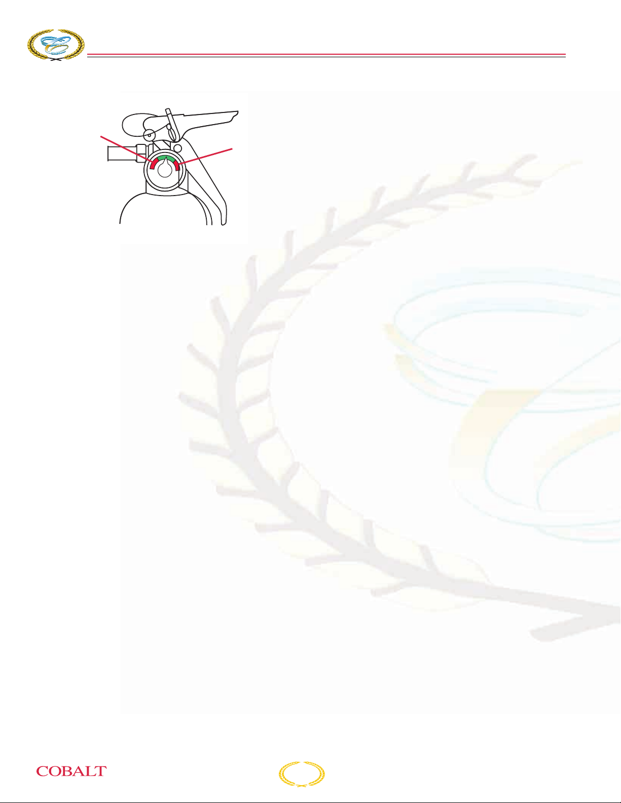
COBALT
1
276
BOWRIDER
2
S
ECTION
Grounding
In the event you run aground, assess the situation
before proceeding. Immediately stop any water
from entering the boat. Inspect the propulsion
unit(s), steering and control systems, and the hull
for damage. Maneuver the boat to safe water only if
the hull and all operating systems are in
satisfactory operating condition. Otherwise, call or
signal for assistance.
2
KC-0083C
1– Recharge
2 – Overcharge
Be sure to:
• Use caution and do not smoke when refueling.
• Verify that fuel does not leak.
• Use only marine approved equipment on your
boat.
Flooding/Swamping
Improper loading, handling, water conditions,
weather and anchoring are the most common
causes of flooding. Insist on a safe, stable load. Do
not operate the boat exceeding your ability to
maneuver it. Use extreme caution in hazardous
weather and rough water conditions. Anchor from
the bow when using one anchor.
Collisions/Leaks
If a collision occurs, immediately account for all
passengers. Assess the hull for damage and
activate the bilge pumps to reduce any water
intake. Try to operate the boat to keep the damaged
area above water. If necessary, call or signal for
assistance. If a leak is discovered, immediately
determine the cause. A collision with an underwater
object could cause the hull to develop a leak. A
loose fitting or hose clamp on a piece of equipment
could cause a leak. Try to repair the leak if possible.
If a leak is threatening the safety of you and your
passengers, call or signal for assistance.
Storms
Take common sense precautions if you are forced
to operate your boat in stormy conditions.
• Wear personal flotation devices (PFDs).
• Stow gear below deck and batten down
equipment on deck.
• Reduce speed and head for a safe place that
you can easily reach.
• If you lose power, keep the boat headed into
the waves by using the anchor.
Water Rescue (Man Overboard)
Immediately react to a person that has fallen
overboard. Keep the victim constantly in your sight.
Safely return to the victim as soon as possible.
Throw the person a PFD. Turn the engines off and
help the person into the boat.
Medical Emergency
Be prepared in the event of an emergency. Know
how to use your first aid kit. Be aware of any special
medical conditions of your passengers.
Drowning
React to a drowning victim the same as described
in Water Rescue. Handle victims with care; they
could be injured. If necessary, resuscitate the
victim. Immediately signal for help and keep the
victim warm.
Operation Failure
If you experience a propulsion, steering or control
failure, immediately turn off the engines. Release
the anchor to prevent drifting. Try to determine the
failure and repair, if possible. Otherwise, call or
signal for assistance.
2-8
276 Owner’s Manual
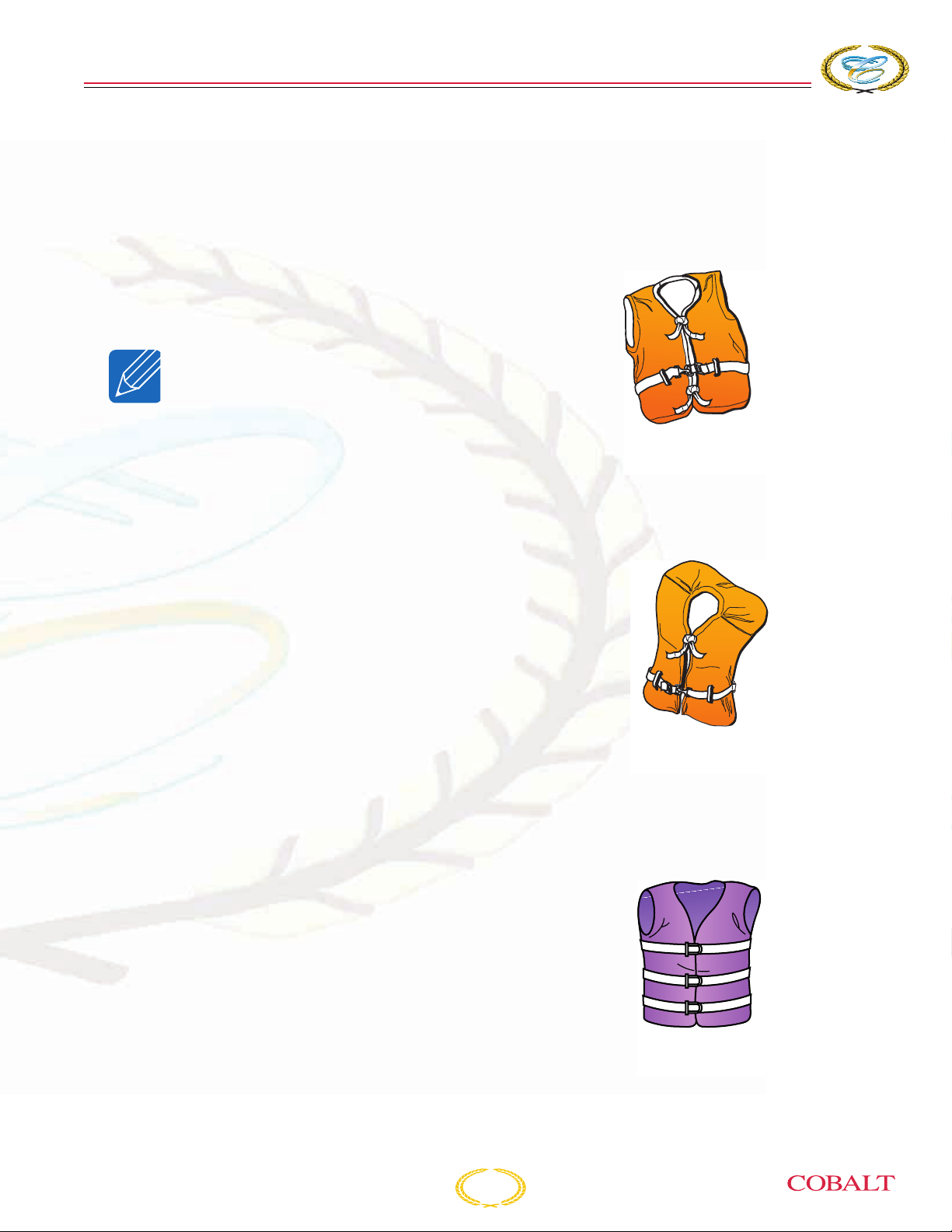
R
ESPONSIBILITIES AND
S
AFETY
Distress Signals
Federal law also requires boats 16 ft (4.8 m) and
longer to carry day and night visual distress signals
when operating on coastal waters, the Great Lakes,
territorial seas or those waters directly connected to
them, up to a point where the body of water is less
than two miles wide. Carry several types of
signaling devices to handle a variety of conditions.
Have enough signals onboard to last three days.
NOTICE: Some pyrotechnics are
restricted from use on certain
bodies of water, so check with
local authorities.
Radio Communication
Radio communication is the most important avenue
of receiving and sending information. Use a
VHF/FM radio for short-range communication, and
a single-sideband radio (SSB) for long-range. For
all U.S. waters, the National Weather Service
operates the NOAA Weather Radio (NWR). This
service provides continuous weather information on
the following VHF/FM frequencies:
There are four types of PFDs to wear and one type
used for throwing in emergency situations.
Type I Life Preserver: Most buoyant PFDs are
effective on all waters, especially open, rough
water.
TYPE I
LIFE PRESERVERS
KC-0041C
Type II Buoyant Vest: Good for calm water near
shore on most inland waters where quick rescue is
likely.
• 162.400 MHz • 162.500 MHz
• 162.425 MHz • 162.525 MHz
• 162.450 MHz • 162.550 MHz
• 162.475 MHz
Coast Guard Marine Information Stations
• 2670.0 kH • 8765.4 kH
• 4428.7 kH • 13113.2 kH
• 6506.4 kH
It is good practice to periodically monitor the
weather.
Lifesaving Equipment
The following equipment may or may not be
required by federal/local regulations.
Personal Flotation Devices
Federal law requires at least one Type I, II, III or V
Personal Flotation Device (PFD) for each person
onboard or being towed, and at least one Type IV
throwable PFD in the boat.
TYPE II
BUOYANT VESTS
KC-0051C
Type III Flotation Aid: Good for most inland water
applications where quick rescue is likely. Comes in
various styles and some are designed for water
sport activities.
TYPE III
FLOTATION AIDS
KC-0042C
276 Owner’s Manual
2-9

COBALT
276
BOWRIDER
S
ECTION
2
Type IV Throwable Device: Intended for heavy
traffic inland waters where help is available.
Designed to be thrown to a person in the water and
should never be worn.
TYPE IV
THROWABLE DEVICES
KC-0071C
Type V Hybrid PFD: Inflatable design for special
use activities and may be used instead of a Type I,
II, or III PFD if used in accordance with the approval
conditions on the label and if worn when the boat is
underway. Some Type V PFDs provide increased
protection against hypothermia.
PFDs are intended to help save lives. The operator
should set an example by wearing a PFD whenever
boating. It is especially important that children and
non-swimmers wear a PFD at all times.
Make certain all passengers know how to put on
and properly adjust their PFDs. Also, selecting the
proper type PFD for your kind of outing helps
ensure your time on the water can be the safest
possible. At the beginning of each season, check
PFDs for damage and test for proper flotation.
Refer to the PFD manufacturer’s information.
Audible/Visual Distress Signals
A distress call is transmitted on VHF/FM radio
channel 16 (156.800 MHz) or 2182 kHz (SSB).
Know your audible signals:
• For emergency, the call sign is “Mayday.”
• For an urgent situation, the call sign is
“Pan-Pan.”
• For navigational safety and weather warnings,
the call sign is “Security.”
Repeat the call sign three times. Immediately react
to a distress call. Assist, if possible, using an
emergency frequency. Otherwise, continue to
monitor the situation until help has arrived.
TYPE V HYBRID PFD
MUST BE WORN
WHEN UNDERWAY
KC-0043C
NOTICE:
• A Type V PFD must be worn to
be counted toward the
minimum carriage
requirements.
• Special PFDs are available for
skiing and other water sports.
These PFDs are constructed
with materials suitable for high
impact falls.
2-10
276 Owner’s Manual
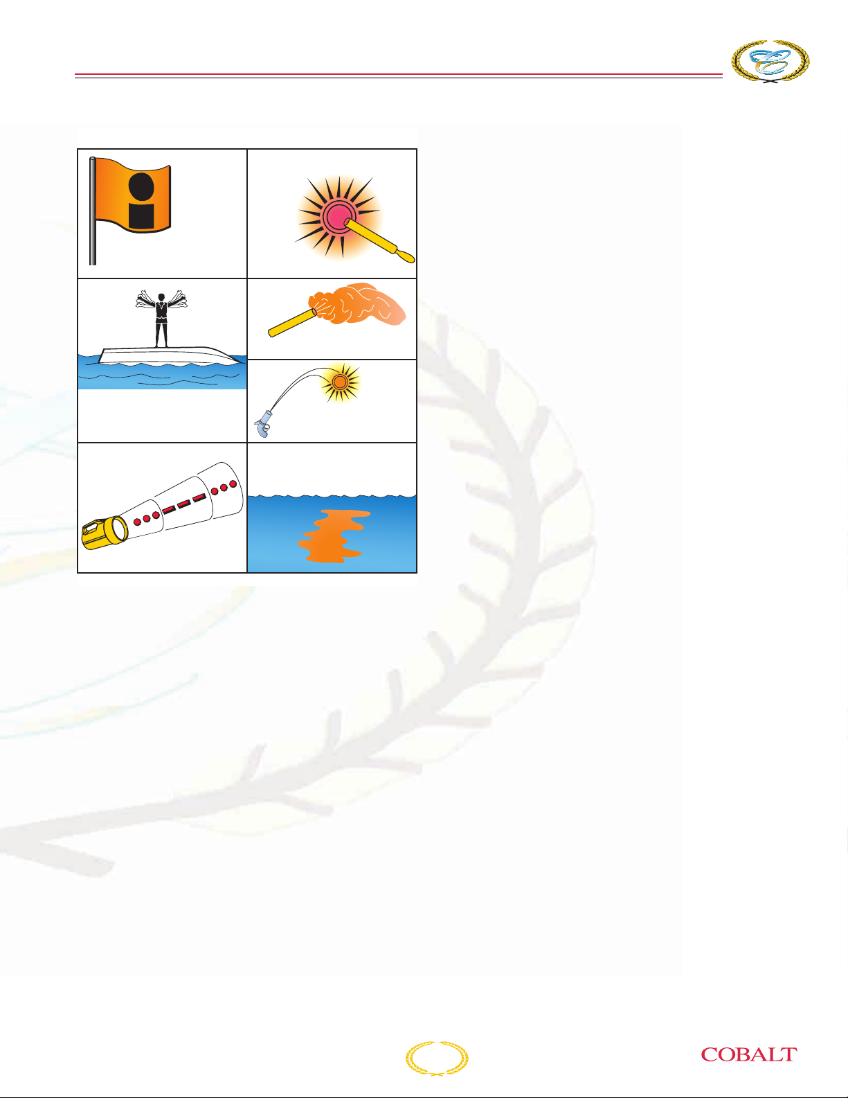
R
ESPONSIBILITIES AND
S
AFETY
VISUAL DISTRESS SIGNALS
USE DAY ONLY
ARMS SIGNALS
(USE BRIGHT CLOTH)
USE DAY ONLY
ELECTRIC
DISTRESS
LIGHT
O
S
RED DISTRESS FLARE
(HAND)
USE DAY AND NIGHT
USE
DAY
ONLY
SIGNAL (HAND)
RED METEOR FLARE
USE DAY AND NIGHT
DYE MARKER
USE DAY ONLY
S
Life Raft
If operating offshore, you should consider carrying
an inflatable life raft. A USCG-approved life raft
meets a number of stringent specifications. The life
raft must be large enough to hold all the boat’s
occupants and have its own equipment pack
including a paddle.
A life raft can be stored in the aft storage area or in
any other accommodating place on your boat.
USE NIGHT ONLY
COB_0031_A
If you are required to carry distress signals, you
must have three USCG-approved pyrotechnic
devices. Be sure they are in serviceable condition,
not exceeding the expiration date and stored in a
cool, dry location in a waterproof container.
Sea Anchors
You should have a separate sea anchor onboard to
slow drifting. In heavy seas, a sea anchor is set
from the bow to control the boat’s behavior. The
sea anchor holds the bow to the sea and a slow
drift.
Radar Reflectors
Radar reflectors allow you to be seen by other
vessels’ radar within your area. Mount the reflector
as high as possible on the radar arch.
276 Owner’s Manual
2-11
COBALT
276
BOWRIDER
SAFETY
The popularity of boating and other water sports
has undergone an immense growth over the past
few years. Because of this, safety is an important
issue for everyone who shares in the use of our
waterways. Be smart when boating and using your
equipment.
In emergency situations, it may be necessary to
resort to measures which are not commonly
practiced. Always assess the dangers of being in
harm’s way versus the protection of equipment.
Keep a sound mind during an emergency and
always think safety.
• Know the conditions of your boat and the
environment.
• Have a float plan and inform others when you
will return.
• Secure or store loose items before getting
underway.
• Avoid sudden maneuvers at high speed and
reduce speed in waves.
S
ECTION
2
A WARNING
Indicates a hazardous situation which, if
not avoided, could result in death or
serious injury.
CAUTION
Indicates a hazardous situation which, if
not avoided, may result in minor or
moderate injury.
NOTICE: Indicates a property
damage message.
The precautions listed in this manual and on your
Cobalt boat are not all-inclusive. If a procedure,
method, tool or part is not specifically
recommended, you must satisfy yourself that it is
safe for you and others, and that the boat will not be
damaged or made unsafe as a result of your
decision. REMEMBER - USE COMMON SENSE
WHEN OPERATING YOUR BOAT!
A WARNING
Avoid fire, explosion, injury or property
damage from improperly handled
pyrotechnic signaling devices. Follow
the manufacturer’s directions.
Signal Words/Definitions
Throughout this manual specific precautions and
symbols identify safety related information.
The Safety Alert Symbol means ATTENTION!
BECOME ALERT! YOUR SAFETY IS INVOLVED!
A DANGER
Indicates a hazardous situation which, if
not avoided, will result in death or
serious injury.
General Safety
Before each outing you should check all safety
equipment, such as fire extinguishers, PFDs, flares,
distress flags, flashlights and engine stop switches.
They should be operable, in good condition, readily
visible and easily accessed.
Check local weather reports before casting off; do
not leave the dock area when strong winds and
electrical storms are in the area or predicted to be
in the area.
Tell someone your travel plans and leave them a
float plan. A float plan makes the job of search and
rescue much easier for authorities. A float plan
template can be found in the back of this manual.
Seating
Keep your passengers seated in seats. The boat’s
bow, gunwale, transom platform and seat backs are
not intended for use as seats while underway.
2-12
276 Owner’s Manual

R
ESPONSIBILITIES AND
S
AFETY
Handholds
A WARNING
Avoid injury or death.
• Passengers should use handholds
whenever the boat is underway.
• DO NOT allow passengers to sit on or
in the stern sun lounges when the boat
is underway.
• Read and understand this manual and
the propulsion unit manual, and be
sure that you understand all controls
and operating instructions before
attempting to operate the boat.
• Be in control of your boat. DO NOT
operate your boat under the influence
of alcohol or other drugs.
Handholds are provided for your passengers’
safety. Be sure your passengers use the handholds
whenever the boat is underway. Failure to use
handholds could result in a man overboard situation
or personal injury.
Capacity
Know the weight capacity of your boat. Do not
overload your boat. Overloading of passengers,
personal equipment and supplies could result in an
accident, especially in rough waters.
Loading
Be sure that passengers, personal equipment and
supplies are in their proper location before
operating the boat. This does not necessarily mean
you can carry a passenger for every seat. Keep
personal equipment and supplies to an “as needed”
basis. Maintain a balanced load (front to back and
side to side) at all times.
Operating Conditions
Every waterway poses hazards that you should
avoid, such as shallow water, tree stumps and sand
bars. Ask local boaters for information and consult
a marine chart when boating on unfamiliar waters.
As the operator of the boat, you should try to avoid
all hazards, known and unknown. The following
information does not contain all possible water
hazards. Operating in shallow water presents a
number of hazards. Mud, sand, weeds and debris
can foul a propulsion unit propeller or its cooling
water. If a propulsion unit strikes an underwater
object, check the propulsion unit and boat for
damage. If a propulsion unit vibrates after striking
an object, it may indicate a damaged propeller.
Sand bars in narrow inlets are constantly shifting,
making it difficult to mark them with buoys. Tides in
coastal areas affect water levels, producing sand
bars. Sometimes sand bars are indicated by waves
as they form into breakers when passing over the
sand bar. Refer to Grounding, in this section, if you
run aground on a sand bar. The water level around
a dam spillway is a hazardous area. It is subject to
rapid changes caused by currents and turbulence.
Keep clear of the spillway areas below dams.
Weather/Seas
Getting caught in severe weather is hazardous. It is
recommended to check the weather, sea and wind
conditions not only before you boat, but also
periodically while you are boating. Refer to Radio
Communications, in this section, for weather
channel information. A change in wave height, wind
direction and speed indicates deteriorating
weather. Take common sense precautions if you
are forced to operate your boat in stormy
conditions:
• Wear PFDs.
• Stow gear below deck and batten down
equipment on deck.
276 Owner’s Manual
• Reduce speed and head for a safe place that
you can easily reach.
If you lose power, keep the boat headed into the
waves by using the anchor.
2-13
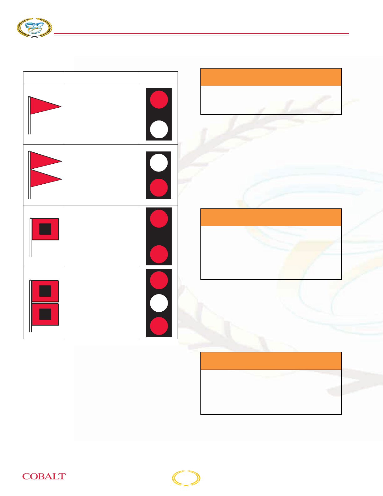
COBALT
276
BOWRIDER
S
ECTION
2
Learn the storm signals.
DAYTIME
WARNING
DESCRIPTION
Small Craft Advisory - Winds
greater than 18 knots,
sustained for two hours or more
or hazardous wave conditions.
Following a storm, hazardous
wave conditions can persist
long after the high winds have
Gale Warning - Sustained
winds (2 or more hours),
of 34-47 knots.
Storm Warning - Sustained
winds of 48 knots or grea
subsided.
ter.
NIGHTTIME
WARNING
Skill/Experience
A WARNING
Avoid injury or death from drowning.
Wear your Personal Flotation Device and
remain seated when operating the boat.
Practice your boat operating skills often in calm
water. Avoid windy conditions and rough water. Be
sure to maintain good visibility at all times. Do not
practice close to any obstructions such as piers,
bridges, swim areas or moored boats.
Proceed slowly and give yourself plenty of time to
react. Remember, your boat is not an automobile. It
requires additional time to maneuver and stop.
Visibility
A WARNING
Avoid injury or death. Maintain clear
visibility at all times. If necessary,
arrange passengers and equipment.
Designate a passenger to assist when
visibility is limited due to operating
conditions.
Hurricane Warning - Forecast
winds of 64 knots and above.
Displayed only in connection
with a hurricane.
COB_0032_A
It is best to avoid operating your boat in foggy
weather. When fog sets in, use your GPS and radar
unit, if equipped, to take bearings and log courses
and speeds. You are required to emit a five-second
blast from your horn or whistle once every minute.
Additionally, have passengers wear PFDs and
observe for oncoming vessels.
Visibility is not only sight, but also hearing. It is very
important the operator maintains good visibility at
all times. Arrange passengers and equipment to
ensure you have unobstructed vision at all times.
Check for other boats or any obstacles before
turning the boat.
Drugs/Alcohol
A WARNING
Avoid injury or death from impaired
operation. Federal and state law prohibit
operating a boat under the influence of
alcohol and other drugs. These
regulations are actively enforced.
2-14
276 Owner’s Manual
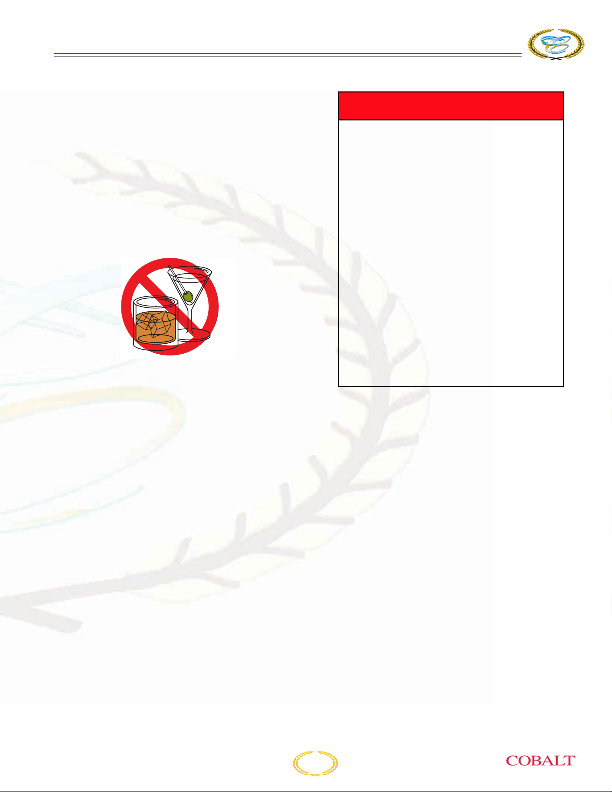
R
ESPONSIBILITIES AND
Boating, alcohol and the use of other drugs just do
not mix. Mixing boating, alcohol and other drugs
results in many marine accidents and deaths.
These substances reduce your reaction time and
affect your better judgment. Combined with the sun,
wind, waves and noise of other watercraft, the
effects of drugs are increased and will significantly
reduce your reaction time. Do not operate your boat
under the influence of alcohol or other drugs. As
the owner/operator, you are responsible for the
alcohol/drug use and onboard behavior of your
passengers.
KC-0153C
If the operator’s blood alcohol content is above the
state’s legal limit, violators are subject to a civil or
criminal penalty, imprisonment or both. Operating a
boat under the influence can also result in a loss of
automobile driving privileges.
Passengers
Whenever you are going for an outing, make sure
that at least one passenger is familiar with the
operation and safety aspects of the boat in case of
emergency. Show all passengers the location of
emergency equipment and explain how to use it.
Do not allow passengers to drag their feet or hands
in the water, or sit on the bow, deck, gunwale or
transom platform while engines are running.
S
AFETY
A DANGER
Avoid the possibility of injury or death
from exposure to carbon monoxide
(CO). All gasoline and diesel engines
and fuel burning appliances such as
heaters, stoves and generators produce
CO. CO is a colorless, odorless and
dangerous gas. Direct and prolonged
exposure to CO will cause brain damage
or death. Signs of exposure to CO
include nausea, dizziness, drowsiness,
ears ringing, headaches,
unconsciousness and cherry red skin
color. Avoid exposing your passengers
or yourself to carbon monoxide. Test the
carbon monoxide detector operation
before each trip, at least once a week
and after the boat has been in storage.
DO NOT tamper with the operation of the
carbon monoxide detector. It is installed
for your safety.
A carbon monoxide (CO) detector will only detect
the presence of carbon monoxide gas at its sensor
and will not detect other vapors such as gasoline.
Carbon monoxide may be present in other areas.
Carbon monoxide poisoning should not be
confused with seasickness, intoxication or heat
stress. If someone complains of irritated eyes,
headache, nausea, weakness or dizziness, or you
suspect carbon monoxide poisoning, immediately
move the person to fresh air, investigate the cause
and take corrective action. Seek medical attention if
necessary.
Ventilation
Your Cobalt boat may be equipped with carbon
monoxide (CO) detector(s), if your boat is a cabin
type or built with an enclosed changing area.
276 Owner’s Manual
2-15

COBALT
276
BOWRIDER
S
ECTION
2
To reduce CO accumulation:
• Ventilate the boat interior by opening the deck
hatches, windows and cabin door to provide
adequate ventilation.
• Do not operate the engines or generator with
the canvas installed.
Blockage of boat exhausts by obstruction. Operating with high bow angle.
Exhausts traveling along obstruction. Exhausts from other vessels in confined areas.
• Avoid idling or using the generator while at idle
for extended periods.
• Regularly inspect the engine and generator
exhaust system for proper operation.
For additional information, refer to the carbon
monoxide detector operator’s manual supplied with
your boat.
Operating at slow speed or while dead in the water. Operating with canvas tops and side
curtains in place without ventilation.
COB_0033_A
2-16
276 Owner’s Manual

R
ESPONSIBILITIES AND
S
AFETY
Qualified Boat Operators
This manual is not intended to provide complete
training on all aspects of boat operation. We
strongly recommend that all operators of this boat
seek additional training on boat handling and
safety. Have all operators become familiar with the
handling characteristics, and proper steering and
control system usage before attempting high-speed
operation.
Some states require youths 16 years of age and
younger to complete a boating safety course before
operating any watercraft. Many others require
operators under the age of 18 to be licensed in
small boat operation.
Minors must be supervised by an adult whenever
operating a boat. Many states have laws regarding
the minimum age and licensing requirements of
minors. Be sure to contact the state boating
authorities for information.
Safety While Boating
Discharge of Oil
The discharge of fuel, oil and other chemicals into
the water is prohibited. Be sure to clean up all fuel
and oil spillage in the bilge using rags and sponges.
Properly store and dispose of them when you get to
shore. Do not allow any fuel or oil spills to be
pumped out into the water. If fuel or oil leaks
continue to be a problem, immediately have the
problem repaired.
When refueling, do not “top-off” the fuel tanks.
Allow for expansion which will reduce fuel spills
from the fuel tank vents.
Solid Waste Disposal
NOTICE: It is illegal to dispose
of any plastic trash into waters
of the U.S.
The disposal of solid waste and plastics into the
water is prohibited. Bag all refuse and properly
dispose of it when you get ashore.
Your Cobalt boat is affixed with various safety
labels at the time of manufacture. These labels
appear at specific locations on the craft where
safety is of particular concern. Refer to Section 1,
Warning Labels.
Safety labels must remain legible. If you suspect a
label is missing or becomes damaged, contact your
authorized Cobalt dealer for immediate
replacement.
Federal, State and Local Regulations
The USCG is the authority of the waterways; it is
there to help the boating public. State boating
regulations are enforced by local authorities. You
are subject to marine traffic laws and “Rules of the
Road” for both federal and state waterways; you
must stop if signaled to do so by enforcement
officers, and permit to be boarded as asked.
Marine Sanitation
NOTICE: Direct disposal of
sanitation waste into some
waters could result in fines. Be
sure to check local regulations.
NOTICE: Avoid damage to the
waste disposal system and the
environment. Do not place facial
tissues, paper towels or sanitary
napkins in the head.
Have your authorized Cobalt dealer properly
service the waste disposal system when needed.
Excessive Noise
Noise limits are regulated in many areas. Be sure
to follow regulations and be courteous.
276 Owner’s Manual
2-17

COBALT
276
BOWRIDER
S
ECTION
2
Wake/Wash
A WARNING
Avoid injury, death or damage to
property. Observe “No Wake” markers.
Use caution when operating around
smaller crafts, in channels and marinas,
and in congested areas. You are
responsible for injury and damage
caused by your wake.
Reporting Accidents
The USCG requires the owner or operator of a boat
involved in an accident to report the incident to the
proper marine law enforcement agency for the state
in which the accident occurred.
Immediate notification to the nearest state boating
authority is required if a person dies or disappears
as a result of a recreational boating accident. If a
person dies or sustains injuries requiring more than
first aid, a formal report must be filed within 48
hours of the accident. A formal report must be filed
within 10 days for accidents exceeding $500 in
property damage or complete loss of boat.
Water Sports Safety
Larger boats produce a larger wake which may be
too big for skiers. Only boats equipped with a ski
tow eye or ski tow pylon should be used to pull
water skiers. If you use your Cobalt boat for water
sports, you should be familiar with water sport
safety and hand signals.
CIRCLE
TURN LEFT
TURN RIGHT
BACK
TO DOCK
SKIER IN WATER
WATER SPORT HAND SIGNALS
NOTICE: It is unlawful to
participate in water sports while
under the influence of alcohol or
other drugs.
When participating in water sports, be safe and
courteous and follow these guidelines:
CUT ENGINE
SPEED FASTER
SPEED SLOWER
SPEED OK
STOP
SKIERS O.K.
KC-0271C
Rendering Assistance
If you see a distress signal or suspect a boat is in
trouble, you must assume it is a real emergency
and render assistance immediately. By law, the
operator in charge of the craft is obligated to
provide assistance to any individual in danger if
such assistance can be provided safely. Failure to
render assistance can result in a fine and/or
imprisonment.
The 1971 Boating Safety Act grants protection to a
“Good Samaritan” boater providing good faith
assistance, and absolves a boater from any civil
liability arising from such assistance.
• Be considerate to fishermen and others you
share the water with.
• Do not perform water sports in congested
areas.
• Stay away from navigation markers.
• Stay away from other boats and water sport
participants.
• Return immediately to a fallen water sport
participant and turn off engines.
• Regularly inspect water sport equipment to
ensure it is safe.
• Do not use any fuel burning appliances with a
transom exhaust port when swimming from the
stern swim platform.
A DANGER
Avoid injury or death. DO NOT practice
unsafe water sports.
2-18
276 Owner’s Manual

R
ESPONSIBILITIES AND
S
AFETY
• Water sport participants must wear a USCG
approved flotation device. A Type III water ski
vest is an approved and practical PFD.
• Keep at least 100 ft (30 m) away from all other
objects.
• Have an experienced driver and aft-facing
observer in the boat when water sporting.
• Do not water sport in shallow water or at night.
• Do not jump from a moving boat.
• Keep a downed water sporter in sight.
• Turn the engine(s) off before you get close to
someone in the water.
• Do not use the boarding ladder with engine(s)
running.
Skiers and/or passengers are obligated to be aware
of the same safety rules as operators. If you are
new to water sports, seek certified training before
starting. You will find it especially helpful to join a
ski club, World Wakeboard Association and/or the
U.S.A. Water Ski when it is possible. Always
remember the majority of water sport injuries result
from impact with other objects.
Always look where you are going and be aware of
your surroundings.
Platform Dragging (“Teak Surfing”)
READ, KNOW and UNDERSTAND the information
on warning labels and adhere to the boat operation
practices described on them. The USCG issued a
SAFETY ALERT on August 28, 2001, which covers
some issues regarding improper use of the
boarding ladder/swim platform. The SAFETY
ALERT and portions of the information follow:
Tragic deaths occur from the negligence of unsafe
boating and dangerous activities. Experts say,
“many of these deaths may have been caused by
an invisible hazard, carbon monoxide poisoning.”
Taking the risk of swimming under a boarding
platform when the engine is running, skiing within
20 ft (6.1 m), or “teak surfing” or “dragging” behind
a moving boat, can be fatal. Dangerous activities
which can result in serious injury or death are not
considered water sports. Cobalt Boats does not
promote unsafe boating risks or jeopardizing any
boater’s safety. “Teak Surfing” or “Platform
Dragging” may be illegal in your state, or the states
you operate in.
A WARNING
Avoid injury or death. DO NOT use the
swim platform for any other purpose
than boarding the boat or preparation of
entering the water, and do not use the
swim platform when engines are
running.
Carbon monoxide poisoning should not
be confused with seasickness,
intoxication or heat stress. If someone
complains of irritated eyes, headache,
nausea, weakness or dizziness, or you
suspect carbon monoxide poisoning,
immediately move the person to fresh
air, investigate the cause and take
corrective action. Seek medical
attention if necessary.
276 Owner’s Manual
2-19

COBALT
276
BOWRIDER
S
ECTION
2
Safety Alert From August 28, 2001:
The United States Coast Guard advised boaters
not to “Teak/Drag Surf.” Recent boating fatalities
revealed carbon monoxide (CO) emitted from a
vessel’s exhaust resulted in CO poisoning and
death. Do not allow persons in the vicinity of the
Swim Platform (in the water or in the boat) with the
engine(s) or generator operating, while at rest or
underway at slow speed. “Teak/Drag Surfing”
places the individual in a position directly exposed
to the CO in the engine’s exhaust. This can result in
a loss of coherent responses and even death. In
addition, “Teak/Drag Surfing” dangerously exposes
the individual to a possible propeller injury. Since
“Teak/Drag Surfing” is done without a life jacket
(PFD), it significantly increases the probability of
drowning. The Coast Guard stresses, “Teak/Drag
Surfing” is a very dangerous activity and advises
boaters not to participate in it.
The Coast Guard also stated that carbon monoxide
is one of the most dangerous gases. It strikes
before you know you are exposed and it impairs in
a way that can, and too often does, lead to death.
This is why the Coast Guard feels it is critical that
CO is avoided in every circumstance.
Navigation
Rules of the Road/Sound Signals
The General Prudential Rule regarding right-of-way
is that if a collision appears unavoidable, neither
boat has right-of-way. As prescribed in the “Rules
of the Road,” both boats must act to avoid collision.
The information in this section outlines only the
most basic of the nautical “Rules of the Road.” For
more information, contact your local USCG
Auxiliary.
Whistle/Horn Signals
Signaling other boats with a whistle or horn is
similar to using turn signals on an automobile. It is
not necessary to sound a signal every time a boat
is nearby. In general, boat operators should signal
their intention, as to avoid potentially confusing or
hazardous situations.
It is customary for the privileged boat to signal first,
and the burdened boat to return the same signal to
acknowledge she understands and will comply. Use
the danger signal (five or more short and rapid
blasts) if intent is not clear.
Use the following signal blast early enough to be
noticed and understood by other boaters:
• One long blast: Warning signal (coming out of
slip or passing astern)
• One short blast: Pass on my port side
• Two short blasts: Pass on my starboard side
• Three short blasts: Engines in reverse
• Five or more short and rapid blasts: Danger
signal!
Privileged Boats
Privileged boats have right-of-way and can hold
course and speed. Sailboats and boats paddled or
rowed have the right-of-way over motor boats.
Sailboats under power are considered motorboats.
Small pleasure craft must yield to large commercial
boats in narrow channels.
Burdened Boats
The burdened boat is the boat that must make the
necessary adjustment to course and speed to keep
out of the way of the privileged boat.
A WARNING
Avoid injury, death or collisions. Like
traffic laws for automobiles, the operator
is legally required to follow the rules.
In general, boats with less maneuverability have
right-of-way over more agile craft. You must stay
clear of the vessel with right-of-way and pass to his
stern.
2-20
276 Owner’s Manual

R
ESPONSIBILITIES AND
S
AFETY
Crossing Situation
In crossing situations, the boat to the right from the
12 o’clock to the 4 o’clock position has the
right-of-way. It must hold course and speed. The
burdened boat keeps clear and passes behind the
privileged boat. Boats going up and down a river
have the privilege over boats crossing the river.
12 O'CLOCK
STAND-ON
(PRIVILEGED)
VESSEL
DANGER ZONE
GIVE-WAY
(BURDENED)
VESSEL
Meeting Head-On
Neither boat has the right-of-way in this situation.
Both boats should decrease speed, should turn to
the right and pass port-to-port. However, if both
boats are on the left side of the channel, each
vessel should sound two short blasts and pass
starboard-to-starboard.
PASSING
PORT TO
PORT
HONK
MEETING
HEAD TO
HONK
HEAD
HONK
HONK
HONK
HONK
PASSING
STARBOARD TO
STARBOARD
COB_0034_A
4 O'CLOCK
COB_0005_A
276 Owner’s Manual
2-21
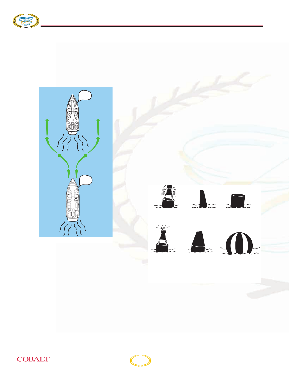
COBALT
276
BOWRIDER
S
ECTION
2
Overtaking
The boat that is overtaking one ahead of it is the
burdened boat and must make any adjustments
necessary to keep out of the way of the privileged
boat. The privileged boat should hold its course
and speed.
HONK
(LONG)
STAND-ON
(PRIVILEGED)
VESSEL BEING
OVERTAKEN
HONK
(LONG)
The size, speed and direction of the other vessels
are determined at night from their running lights. A
green light indicates the starboard side of the boat,
and a red light indicates the port side. Generally, if
you see a green light, you have the right-of-way; if
you see a red light, give-way to that vessel.
Aids to Navigation
Learn to recognize the different buoys and day
markers; they are the signposts of the waterways.
The United States Aids to Navigation System
(USATONS) is the primary marking system used on
inland water, coastal waters and rivers. This system
is maintained by the U.S. Coast Guard (USCG).
Types of Buoys
There are several types and shapes of buoys.
Buoys may be unlighted, lighted, with sound or may
have both an audible and a visual signal. Lights,
bells and horns are used on buoys for night or poor
visibility conditions. Different shapes of buoys are
shown below.
GIVE-WAY
(BURDENED)
VESSEL
OVERTAKING
COB_0035_A
Special Situations
Boats operating between sunset and sunrise
(hours vary by state) must use navigational lights,
nighttime operation, especially during bad weather
or fog can be dangerous. All “Rules of the Road”
apply at night; it is best to slow down and stay clear
of all boats, regardless of who has right-of-way.
Protect your night vision by avoiding bright lights
and have a passenger, if possible, help keep watch
for other boats, water hazards and aids to
navigation.
UNLIGHTED
BELL BUOY
LIGHTED BUOY
SPAR B UOY
NUN BUOY
CAN BUOY
SPHERICAL SAFE
WATER MARKER
KC-1908
Buoys with unique light-flashing characteristics are
identified on nautical charts with the specific
flashing pattern.
2-22
276 Owner’s Manual
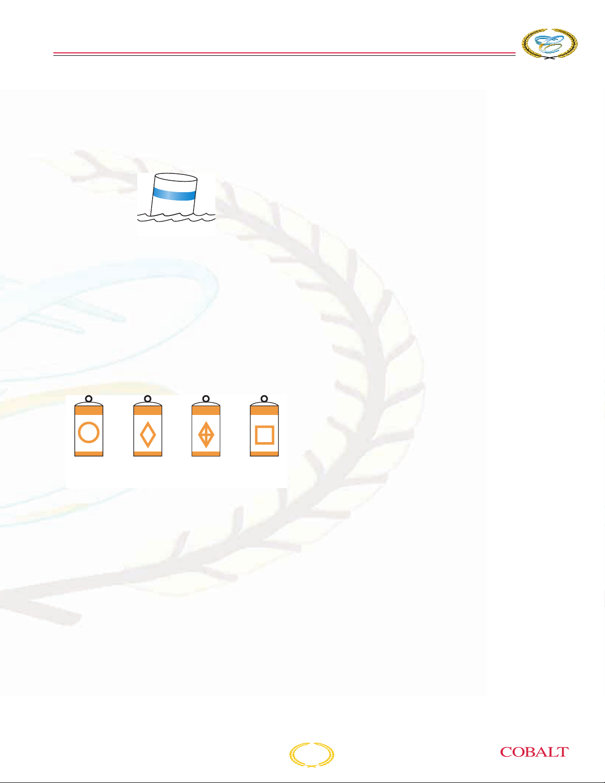
R
ESPONSIBILITIES AND
Mooring Buoys
The only buoys you are permitted to moor to are
mooring buoys. Mooring buoys are white with a
blue horizontal stripe. Mooring to a navigation buoy,
regulatory markers or lateral markers is illegal.
KC-1901
Regulatory Markers
Regulatory markers indicate dangerous or
restricted controlled areas. These markers are
used to indicate speed zones, areas set aside for
particular use, general information and directions.
S
AFETY
Regulatory markers are white with orange
geometric shapes and also have orange bands
near the top and at the water line of the buoy. You
must obey regulatory markers (see below).
CONTROLLED
AREA
DANGER BOATS
KEEP OUT
INFORMATION
KC-1903
276 Owner’s Manual
2-23
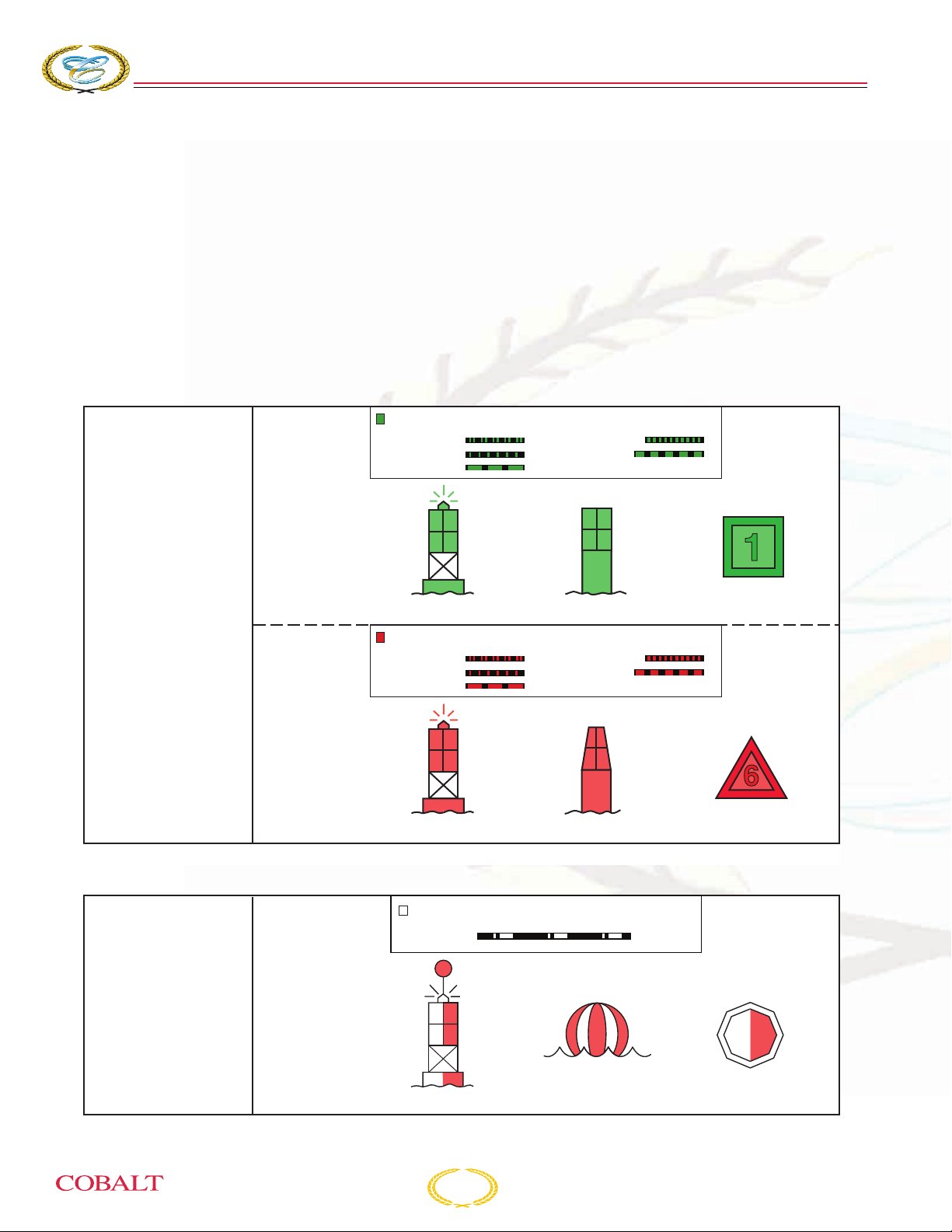
COBALT
276
BOWRIDER
S
ECTION
2
Lateral Markers
Lateral markers are oriented from the perspective
of being entered from seaward (the boater is going
toward the port). This means that red buoys are
passed on the starboard (right) side of the vessel
when proceeding from open water into port, and
green buoys to the port (left) side.
The right side (starboard) of the channel is marked
with RED, even-numbered buoys. The left side
(port) of the channel is marked with GREEN,
odd-numbered buoys.
GREEN LIGHT ONLY
Flashing (2)
Flashing
Occulting
Port Side
Odd Numbers
Lateral Aids Marking
the Sides of Channels
as Seen When Entering
From Seaward
Lighted Buoy
RED LIGHT ONLY
Flashing (2)
Flashing
Occulting
Day markers are colored and numbered the same
as buoys. RED, triangular day markers with even
numbers mark the starboard side of the channel.
GREEN, square day markers with odd numbers
mark the port side of the channel.
Fairways and mid-channels may be marked with
safe water marks or buoys. These marks indicate
safe water all around. Safe water marks are red
and white striped and are round or have a red
spherical topmark.
Quick Flashing
Iso
3
Quick Flashing
Iso
5
Daymark
Can Buoy
Safe Water Aids
Marking Mid-Channels
and Fairways
(No Numbers–May be
Lettered)
Starboard Side
Even Numbers
2
Lighted Buoy
WHITE LIGHT ONLY MORSE CODE
Mo (A)
G
Spherical Buoy
Lighted
2-24
4
Nun Buoy
E
Daymark
KC-1909
C
Daymark
KC-1910
276 Owner’s Manual
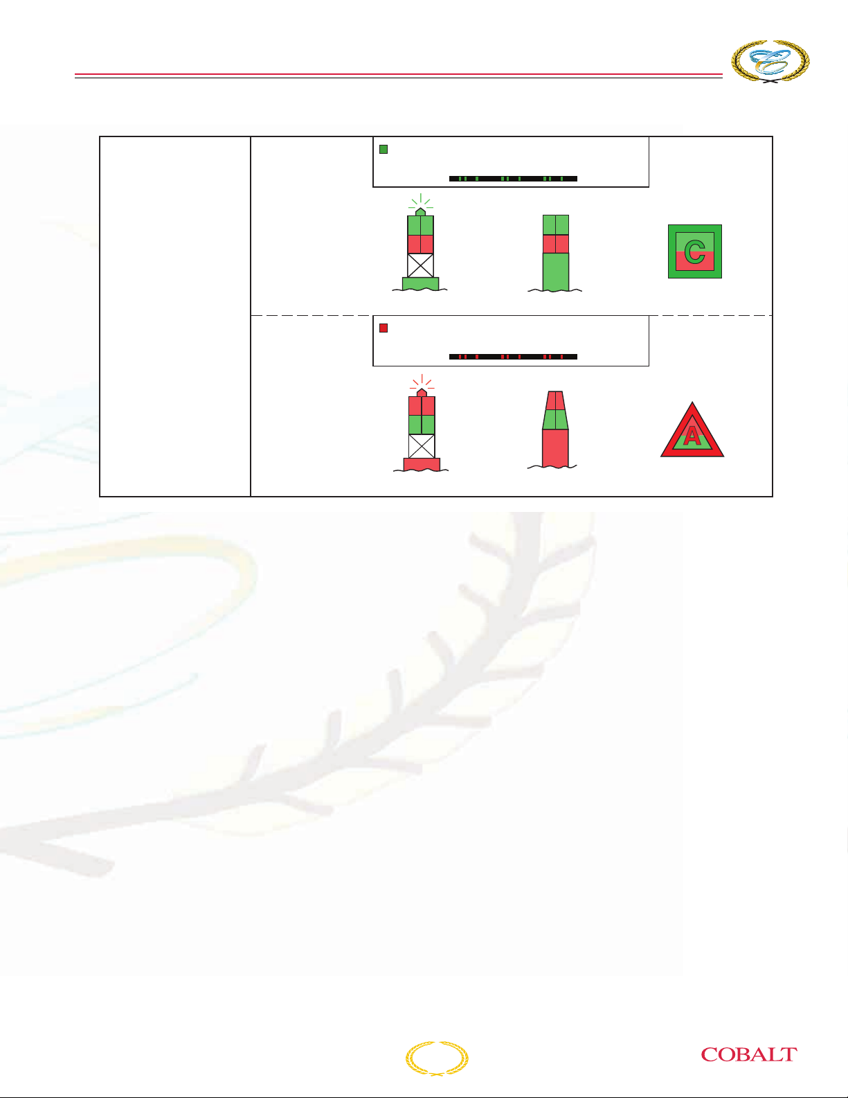
R
ESPONSIBILITIES AND
GREEN LIGHT ONLY
Composite Group Flashing (2+1)
S
AFETY
Preferred
Channel
to Starboard
Preferred Channel Aids
(No Numbers–May be
Lettered)
Preferred
Channel
to Port
Lighted Buoy
RED LIGHT ONLY
Composite Group Flashing (2+1)
Lighted Buoy
Obstructions, channel junctions, etc. are marked
with RED and GREEN horizontally striped buoys.
A RED band at the top means the preferred
channel is to the left of the buoy; a GREEN top
band means the preferred channel is to the right of
the buoy.
L
B
Daymark
Can Buoy
H
D
Nun Buoy
Daymark
KC-1911
276 Owner’s Manual
2-25

COBALT
Isolated Danger Markers
Isolated danger markers indicate an isolated
danger which may be passed on all sides. These
markers are colored black with one or more broad
horizontal red bands and are equipped with a
topmark of two black spheres, one above the other.
Isolated Danger
(No Numbers–May be
Lettered)
276
BOWRIDER
WHITE LIGHT ONLY
FI (2) 5s
Lighted Unlighted
C
S
ECTION
2
KC-1912
On inland waters, a buoy with alternating vertical
black and white stripes may be used to indicate that
an obstruction or other danger exists between the
buoy and the nearest shore. DO NOT pass
between the buoy and the shore.
BLACK-STRIPED
WHITE BUOY
KC-1902
Light Structures
Maneuvering a boat at night can be dangerous and
confusing. To aid boaters with navigation and warn
of hazards, the USCG and the state and local
authorities maintain a variety of light structures.
Some light structures may be equipped with radio
beacons, radar reflectors and/or signals.
Minor Lights
Minor lights are colored according to the buoyage
marking system in use. They are similar to lighted
buoys, except they are usually higher and on more
stable platforms to increase visibility. Most minor
lights are part of a series to mark a channel, river or
harbor.
2-26
276 Owner’s Manual

R
ESPONSIBILITIES AND
Range Lights
Range lights are usually visible in one direction and
help a boat operator navigate in a generally safe
direction. Steering a course to keep range lights
arranged in a line (one on top of the other) will help
guide a boat through a channel.
RANGE LIGHTS
FRONT
MARKER
S
AFETY
REAR
MARKER
LEFT OF RANGE LINE RIGHT OF RANGE LINE
ON RANGE LINE
Lighthouses
Lighthouses can be found at harbor entrances,
prominent headlands, isolated danger areas and
along the coast. These striped or patterned
structures have unique flashing characteristics to
help identify them.
COB_0038_A
276 Owner’s Manual
KC-0443C
2-27
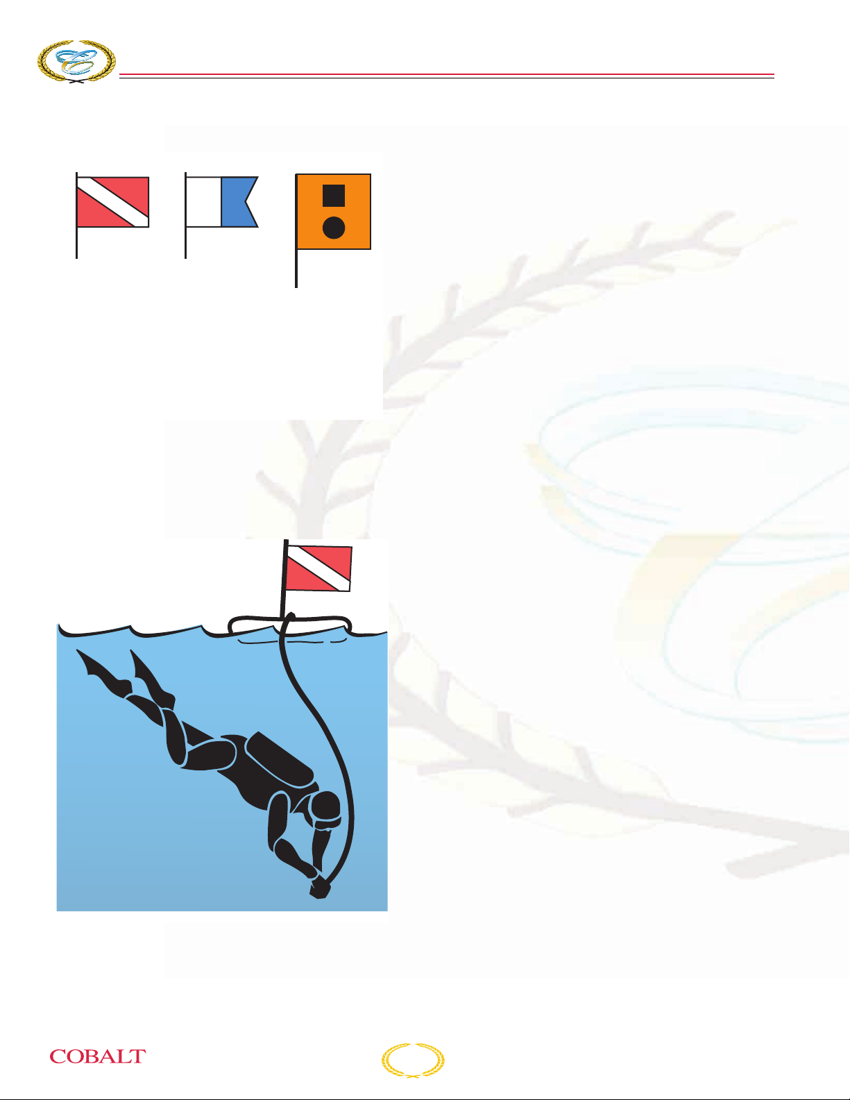
COBALT
Warning Markers
276
BOWRIDER
S
ECTION
2
DIVERS FLAG
USED BY
RECREATIONAL
DIVERS -
INDICATES
DIVER'S
POSITION
ALPHA FLAG
WORLDWIDE
VESSELS
ENGAGED
IN DIVING
OPERATIONS -
DOES NOT
INDICATE
DIVER'S
POSITION
DISTRESS FLAG
INDICATES
FELLOW
BOATER IS IN
NEED OF
ASSISTANCE
COB_0039_A
It is a good idea to ask local authorities if there are
hazardous areas in the waters in which you plan to
boat, and how they are marked. Boaters must also
recognize the flag designs which indicate that skin
divers are present and keep well clear of the area.
KC-0250C
Watch for swimmers. Swimming areas may not be
marked. Steer clear from the area and remain alert.
2-28
276 Owner’s Manual

276 Owner’s Manual
O
PERATING
I
NFORMATION
S
ECTION
3
This section is not intended to provide complete
training on all aspects of boat operation.
We strongly recommend that all operators of this
Cobalt boat seek additional training on boat
handling and safety. Have all operators become
familiar with the handling characteristics and proper
steering and control system usage before
attempting operation and especially high-speed
operation.
The features described in this section are standard
or optional, depending on your model. Refer to
Standard Equipment and Optional Equipment,
in this section, for a list of features for this model.
PRECAUTIONS
Before You Start
Become familiar with the location and operation of
all equipment. Have emergency plans in place. Be
sure to perform a safety check before operating
your boat.
Fire/Explosion
Most fires are the result of fuel and oil accumulating
in the bilge from careless fueling practices. Use the
fire extinguisher at the base of the flames using a
sweeping motion. Prudent and accurate use of the
available chemicals should contain all but the worst
fires. Verify that the fire has been extinguished. If
so, check damage and get assistance immediately.
If not, get out and swim at least 25 yards
(23 meters) upwind from the boat and use the
visual distress signals to get assistance. Refer to
Section 2, Safety, for additional information.
FIRST-TIME OPERATION
A WARNING
Avoid injury or death. Improper
operation can be extremely hazardous.
Read and understand this manual, the
propulsion unit operator’s manual and
any other accessory or components of
your boat. Be sure that you understand
all controls and operating instructions
before attempting to operate the boat.
Your safety, the safety of your passengers, and the
safety of other boaters are among your
responsibilities as operator of this boat.
Your boat must be in compliance with USCG safety
equipment regulations.
You should know how to react correctly to adverse
weather conditions, have good navigation skills and
follow the “rules of the road” as defined by the
USCG and state, county and local regulations.
We cannot stress enough the importance of
reading your propulsion unit operator’s manual and
following the manufacturer’s instructions for
breaking in your engine.
Before each outing you should check all safety
equipment, such as fire extinguishers, PFDs, flares,
distress flags, flashlights and engine stop switch.
They should be operable, in good condition, readily
visible and easily accessed.
276 Owner’s Manual
3-1
COBALT
276
BOWRIDER
S
ECTION
3
FUEL
Fuel Requirements
Cobalt fuel systems are designed to meet all
current ABYC and NMMA regulations using
gasoline with up to 10% ethanol.
A WARNING
DO NOT use fuels containing methanol
(methyl alcohol) or other fuels with more
than 10% ethanol (ethyl alcohol) content
such as E85, which contains 85%
ethanol.
Fuel that contains more than 10% ethanol voids all
warranties and will increase the risk of damage to
the engine, fuel system components and will also
lead to the following:
• Corrosion of metal parts
• Deterioration of plastic, rubber parts or
permeation of fuel through rubber fuel lines
• Leaking fuel resulting in explosion and/or fire
• Starting and operating difficulties
• Potential damage to your engine
NOTICE: Prevent unwarranted
engine damage. Use the
recommended fuel type and
octane rating. Refer to your
propulsion unit operator’s
manual.
A DANGER
Avoid injury, fire or explosion. Fuels are
extremely flammable and highly
explosive under certain conditions.
• Stop engines, generators and any fuel
operated machinery.
• DO NOT smoke or allow open flames
or sparks within 50 ft (15 m) of the
fueling area.
• Avoid damaging fuel lines and
connectors, and the contact of fuel on
hot engine parts.
• DO NOT store fuel in any containers or
compartments which are not
designated for fuel storage.
• Clean up any spilled fuel immediately
and dispose of rags properly ashore.
Fueling
Take care not to spill gasoline. If gasoline is
accidentally spilled, wipe up all traces of it with dry
rags and immediately dispose of the rags properly
ashore. Spilled fuel may yellow the gelcoat finish
and damage gunwale trim.
A DANGER
Avoid injury, fire or explosion. Take all
precautions every time you fuel your
boat, regardless of the fuel type. Certain
fuel is extremely flammable and highly
explosive under certain conditions.
Fumes from rags can collect in bilge and
be extremely hazardous. Operate the
blowers for at least four minutes. DO
NOT store rags used to wipe up fuel or
solvent spills in the boat. Dispose of
rags properly ashore.
• Know the dangers associated with
fuels.
NOTICE:
• Each time you refuel, inspect
all fuel lines, hoses and
connections for leaks and
deterioration.
• The Federal Water Pollution
Control Act prohibits the
discharge of oil or oily waste
into the water. Violators can be
fined $5,000.00. We urge you
to protect our fragile
environment by avoiding any
type of discharge, trash or
litter into our waterways.
3-2
276 Owner’s Manual

O
PERATING
When Fueling:
1. Know your fuel tank capacity. Be sure to have
enough fuel to reach your destination. If
departing for an extended cruise, know the
availability of fuel along your route. Practice the
One Third Rule: one third to reach the
destination, one third to return and one third in
reserve.
2. Avoid fueling at night, except under well-lighted
conditions.
3. Moor your boat securely to the dock. Know the
location of the fire extinguisher in case of
emergency.
4. Keep accurate records of your fuel
consumption. A fuel log tracking fuel use over
time will help determine average consumption.
5. Close all doors, hatches, windows and other
compartments.
6. Extinguish cigarettes, pipes and all other flame
producing items.
7. Make sure all power is off, and do not operate
any electrical switches.
8. Remove the fuel filler cap.
9. Insert the hose nozzle and make sure nozzle is
in contact with or grounded against fill opening.
This will reduce the risk of static spark.
I
NFORMATION
COB_0040_A
To c l o se :
Reinstall cap, press and turn clockwise. The fuel
cap key is not necessary unless the cap is
overtightened.
10. Add fuel in accordance with the propulsion unit
operator’s manual. Do not overfill, and allow
enough room for fuel expansion.
The fuel cap is retained by a chain, to prevent
losing the cap after it is opened. Be careful when
fueling to avoid damaging the chain. If it breaks,
have it replaced.
After Fueling:
1. Tighten the fuel fill cap using the fuel cap key,
unless your filler cap is the pop-up type. Wipe
up any fuel spills.
KC-0991
When your boat is equipped with the pop-up fuel
filler cap, open by pressing the cap and turning the
cap counterclockwise (approximately 10°); remove
cap.
276 Owner’s Manual
2. Open all windows, hatches, doors and
compartments.
3. Check all fuel lines, hoses and connections for
leaks and deterioration.
4. Be sure to run the blower for at least four
minutes before starting the engine. If you smell
gasoline fumes, do not start the engine;
continue to run the blower until fumes have
dissipated.
3-3

COBALT
276
BOWRIDER
S
ECTION
3
LAUNCHING
Launching Checklist
Federal and local laws require certain safety
equipment to be onboard at all times. In addition,
responsible boaters carry other equipment in case
of an emergency. Check with local boating
authorities for any additional requirements over and
above federal requirements.
For maximum enjoyment and safety, check each of
these items BEFORE launching:
• Install drain plug.
• Have enough personal flotation devices for
every person onboard.
• Be sure the steering system operates smoothly
and properly.
• Verify the amount of fuel in the fuel tanks.
• Verify the batteries are fully charged.
• Check weather conditions.
• Be sure the lights, horn, bilge pumps and other
electrical equipment are in proper operating
condition.
Loading
Do not overload your boat. The performance of
your boat is dependent on load weight and
distribution. Passengers should distribute
themselves to maintain trim. Remember to
distribute weight from right to left, and also from
front to back.
• Avoid excess weight in the bow or stern.
• Securely stow all extra gear in stowage areas
to prevent load shifting. Do not stow gear on top
of safety equipment; safety equipment must be
quickly accessible.
• In adverse weather, reduce the load in the boat.
People/load capacity ratings are based upon
normal boating conditions.
• Do not use the drive unit as a boarding ramp;
use the boarding ladder. To prevent injury,
make sure the engine is off when swimmers,
divers and skiers are boarding.
Overloading of passengers, personal equipment
and supplies could result in an accident, especially
in rough waters. Maintain a balanced load at all
times.
• Be sure the fire extinguisher, signaling devices
and other emergency gear are onboard and in
proper operating condition.
On the Water
Start your engine before casting off. Remember,
the boat turns from the stern. Allow plenty of space
between the boat and the dock before trying to
move away.
Boarding
When boarding the boat, always step in. Do not
jump. Avoid stepping on fiberglass or other
potentially slippery surfaces. Board one person at a
time.
Do not board the boat while carrying gear. Set the
gear on the dock, board the boat and then pick up
the gear.
Shipshape
Keep the weight distributed evenly. Store all gear in
secure areas. Safety equipment must be
immediately accessible at all times.
A DANGER
Avoid injury or death. All passengers
should be carefully seated while the
boat is moving. DO NOT sit on the bow,
bow pulpit, deck, gunwale or sundeck
pads when the boat is moving.
3-4
276 Owner’s Manual

O
PERATING
I
NFORMATION
GETTING UNDERWAY
There are many things to consider when planning a
safe and enjoyable boating trip.
You are responsible for the safety of all passengers,
the boat and any damage the boat or its wake may
cause. Keep passengers from blocking your view
so that you do not run into other boats, swimmers,
water skiers, personal water vehicles or aids to
navigation.
Before Starting Checklist
The following checks are essential to safe boating
and must be performed before starting the engine.
Get into the habit of performing these checks in the
same order each time so that it becomes routine.
Pre-Operation:
• Refer to Section 5, Before Every Use.
• Refer to Launching Checklist, in this section.
• Test operation of carbon monoxide detectors.
• Open all seacocks and check for leaks.
• Check seawater strainers for leaks and
accumulation of debris.
• Open windows, doors and hatches.
• Check that no fuel, oil or water is leaking or has
leaked into the bilge compartment.
• Check all hoses and connections for leaks and
damage.
• Verify the shift lever is in the NEUTRAL
position.
• Check that the steering system operates
properly.
During Operation:
• Check gauges frequently for signs of abnormal
operation.
• Check that steering, shift and throttle controls
continue to operate smoothly.
• Check for excessive vibration.
• Monitor your fuel supply.
• Verify batteries are charged.
After Boating:
• To prevent marine growth from accumulating
on the hydraulic cylinder shafts, make sure trim
tabs are up and propulsion unit drives are in the
full trim DOWN position.
• Remove the ignition keys.
• Stow and secure all equipment.
• Pump bilges dry with manual switch.
• Close all water inlet seacocks.
• If possible, inspect the hull and propellers for
damage.
• Check for fuel, oil and water leaks.
• Clean any spills, stains or moisture from the
boat. Inspect sea strainers.
• Turn battery select switches off.
• Turn off DC breaker on electrical panel and if
not using shore power, turn off AC breaker.
• Remove any food, garbage and wet gear from
the boat.
• Secure lockers, hatches and canvas as
equipped.
A DANGER
Avoid injury or death. DO NOT operate
the boat if any problem is found during
this inspection. A problem could lead to
an accident when using an unsafe boat.
Immediately have any problem attended
to by your authorized Cobalt dealer.
• Operate bilge blowers for at least four minutes
before starting engines or generators.
• Do not overload your boat.
276 Owner’s Manual
3-5

COBALT
276
BOWRIDER
S
ECTION
3
Handling Dock and Mooring Lines
Be sure to use enough fenders to protect your boat
from damage. Only use good quality,
double-braided nylon line. Protect your boat’s finish
by using chafing protectors on the lines. Only use
the cleats, bow eye and stern eyes to secure your
boat. Do not use the handrails or windshield. The
foredeck handrails should only be used for tying a
“Jackline” in an emergency situation. If possible, tie
up your boat with the bow toward the waves and
leave a little slack in the lines to allow for some
wave movement or tidal action.
2
1
1 – Stern Line
2 – Forward Quarter Spring
3 – After Bow Spring
4 – Bow Line
Use your dock lines to help maneuver the boat near
the pier and to secure it. Use the following
information to secure your boat to a pile or dock
cleat:
The bow line is fastened to the bow cleat and is
pulled forward at about a 45° angle. This line keeps
the boat from moving astern.
The stern line is fastened to an after cleat and
pulled astern at about a 45° angle. This line keeps
the boat from moving forward.
The spring lines can help you control the boat when
leaving a dock. Be sure to use spring lines when
boating in waters where the tide movement is
significant. The forward quarter spring line is
fastened to a forward cleat and heads aft. The after
bow spring is fastened to a stern cleat and heads
forward.
3 4
COB_0060_A
Starting/Shifting/Steering/Stopping
Your Cobalt boat may be equipped with a warning
system that will sound an alarm if an engine
problem develops. The horn may emit a short
chirping sound during starting to verify operation. If
the warning horn sounds when operating the boat,
IMMEDIATELY throttle back to idle speed and shift
into the NEUTRAL position. IMMEDIATELY check
the gauges and stop the engine.
NOTICE: Continued operation
after the warning alarm has
sounded may cause severe
engine damage.
Carbon Monoxide Detectors, if equipped
Avoid the possibility of injury or death from
exposure to carbon monoxide (CO). All gasoline
and diesel engines and fuel burning appliances
such as heaters, stoves and generators produce
CO. CO is colorless, odorless and dangerous.
Direct and prolonged exposure to CO will cause
brain damage or death. Signs of exposure to CO
include nausea, dizziness, drowsiness, ears
ringing, headaches, unconsciousness and cherry
red skin color. Avoid exposing your passengers and
yourself to carbon monoxide. Test the CO detector
operation before each trip, at least once a week
and after the boat has been in storage. Do not
tamper with the operation of the CO detector. The
detectors are installed for your safety.
Carbon monoxide poisoning should not be
confused with seasickness, intoxication or heat
stress. If someone complains of irritated eyes,
headache, nausea, weakness or dizziness, or you
suspect carbon monoxide poisoning, immediately
move the person to fresh air, investigate the cause
and take corrective action. Seek medical attention if
necessary.
3-6
276 Owner’s Manual

O
PERATING
I
NFORMATION
Starting the Engine
A DANGER
Avoid death, injury, fire or explosion.
Operate the blower for at least four
minutes each time you start the engine.
In addition, the blower should be
operated continuously when at idle and
during slow speed operation.
Cobalt Check List
For maximum enjoyment and safety, check each of
these items.
BEFORE you start your engine:
• DRAIN PLUG (Securely in place?)
• PERSONAL FLOTATION DEVICES (One for
every person onboard?)
• STEERING SYSTEM (Working smoothly and
properly?)
• FUEL SYSTEM (Adequate fuel? Leaks?
Fumes?)
• BATTERY (Fully charged? Proper water level?)
• ENGINE (In the NEUTRAL position?)
• CAPACITY PLATE (Are you overloaded or
overpowered?)
• WEATHER CONDITIONS (Safe to go out?)
• ELECTRICAL EQUIPMENT (Lights, horn,
pump, etc.?)
• EMERGENCY GEAR (Fire extinguisher,
bailer, paddle, anchor and line, signaling
device, tool kit, etc.?)
RECOMMENDED SAFETY RULES
• REMAIN SEATED WHILE UNDERWAY.
• AVOID USING REAR PAD OR SUNDECK
WHILE ENGINE IS RUNNING.
• DO NOT USE BOARDING LADDER WHILE
ENGINE IS RUNNING.
• TURN OFF ENGINE AND ALL ELECTRICAL
SYSTEMS WHILE REFUELING.
• TURN OFF ENGINE WHEN SWIMMERS ARE
NEAR BOAT.
After launching and pre-start checks and
procedures have been followed, the engine can be
started. Please refer to the propulsion unit
operator’s manual for additional starting procedure
information.
Start the engine with the shift control lever in the
NEUTRAL position. Your boat is equipped with a
neutral safety switch which will not allow engine to
be started unless the shift control levers are in the
NEUTRAL position.
Make sure:
• Control lever is in the NEUTRAL position.
• Throttle lever is at the IDLE position.
1. Turn the ignition key to START position.
Release the key immediately after the engine
starts. If the engine fails to start, refer to the
propulsion unit operator’s manual for additional
information.
NOTICE: Release the ignition
key after the engine starts. Do
not run the start motor for more
than 10 seconds at a time.
Failure to follow this procedure
can damage an engine and the
engine’s starter motor.
2. Operate the engine at approximately 1,000
RPM and check the oil pressure gauge. If oil
pressure is not within specified range, stop the
engine immediately. Have your authorized
Cobalt dealer service the engine.
3. Make sure the water pressure gauge indicates
water pressure immediately after starting the
engine. If it does not, turn off the engine and
contact your authorized Cobalt dealer.
4. Allow the engine to warm up. Check the water
temperature gauge to be sure water
temperature remains within the specified range.
If the temperature gauge reads abnormally high,
stop the engine immediately. Check the drive unit’s
water inlets for blockage. If the inlets are open,
have your authorized Cobalt dealer service the
engine.
276 Owner’s Manual
3-7

COBALT
Shifting/Running
276
BOWRIDER
CAUTION
Avoid injury, swamping the boat or
taking water in over the transom. Go
slowly when traversing in reverse.
Follow these guidelines when shifting your boat:
• Pause in the NEUTRAL position before shifting
from FORWARD to REVERSE, or REVERSE
to FORWARD.
• Avoid shifting into REVERSE while the boat is
traveling forward at speed.
• Keep the control area clean and clear of
obstructions.
1 – Release Lever
S
ECTION
1
COB029
3
Steering
A DANGER
Avoid injury or death. The steering
system is the most important system in
the entire boat from a safety standpoint.
The boat’s steering system is not
self-centering. Propeller torque, trim
setting, water condition and boat speed
affect the steering. Constant attention to
the steering system is required for safe
operation. Have the system inspected
and maintained on a quarterly basis by a
qualified service technician.
Your Cobalt boat is equipped with a tilt steering
wheel. Adjust the tilt position with the release lever.
A WARNING
Avoid loss of control and/or injury. DO
NOT adjust the steering wheel tilt
position while the boat is moving.
Sudden boat movement may cause loss
of balance resulting in loss of control.
The steering system must be working correctly and
properly maintained. Be sure to:
• Keep mooring lines, tow lines and other
obstructions clear of the steering system.
• Keep the steering system’s moving parts clean
and lubricated.
• Regularly inspect the steering system for
kinks, damage and corrosion.
Refer to Basic Maneuvering, in this section, for
additional steering information.
3-8
276 Owner’s Manual

O
PERATING
I
NFORMATION
RIGHT TURN
Turn wheel to right—Stern
will move to left.
LEFT TURN
Turn wheel to left—Stern
will move to right.
BACKING TO LEFT
Turn wheel to left—Stern
will pull to left.
COB_0062_A
276 Owner’s Manual
3-9

COBALT
276
BOWRIDER
S
ECTION
3
Stopping the Engine
A WARNING
Avoid creating a hazardous condition.
DO NOT use the engine stop switch and
lanyard for normal stopping of the
engine. Using the stop switch will impair
your ability to restart the engine quickly
if a hazardous situation arises.
1. Slowly bring the throttle lever to the IDLE
position, or the NEUTRAL position.
2. Move the shift lever to NEUTRAL.
3. After operating at high speeds, allow a 2-3
minute engine cooldown period at low idle.
4. Turn the ignition key to the OFF position.
NOTICE: If any problems are
encountered during the outing,
have your boat inspected by
your authorized Cobalt dealer
and request any necessary
repairs before your next outing.
Returning
A WARNING
Avoid injury. DO NOT use your hands,
arms or another part of your body to
attempt to keep the boat from hitting the
dock.
Approach a dock slowly and use caution. Plan your
maneuvers ahead of time. Allow wind and current
movement to help maneuver your boat.
Be sure to read Basic Maneuvering, in this
section.
Leaving
Use caution when casting off. Wind, water
conditions and other boat traffic will affect your
boat’s movement. Move slowly and:
• Be sure the engine is warmed up before
casting off.
• Have enough space between the boat and the
dock to allow you to swing the boat’s bow away
from the dock. The boat’s stern will move
toward the dock as the bow moves away. Allow
for enough room or the stern will hit the dock.
• Retrieve all mooring lines and fenders.
• Proceed slowly. Sound a long blast to alert
other boaters that you are departing.
When leaving a mooring, you should already have
enough space around the boat to maneuver. Untie
from the mooring and move back slowly until you
can see it. Proceed slowly while giving the buoy
wide clearance.
3-10
276 Owner’s Manual

O
PERATING
I
NFORMATION
WIND or CURRENT
WIND or CURRENT
COB_0063_A
Docking
Follow these guidelines when docking:
• Come to a stop a short distance from the dock,
then proceed slowly.
• Have your fenders, mooring lines and the crew
ready.
• Observe how the wind and current are moving
your boat. Approach the dock with the boat
pointed into the wind, if possible. If the wind or
current is pushing you away from the dock, use
a sharper angle of approach. If you must
approach the dock downwind or down current,
use a slow speed and shallow angle. Be ready
to reverse in order to stop and maintain
position.
• If there is no wind or current, approach the dock
at a 10° to 20° angle.
• If possible, throw a line to a person on the dock
and have that person secure a bow line. If no
one is on the dock, maneuver as close as you
can, then secure any line to a piling or dock
cleat.
• With the bow secure, swing the stern in using
engine thrust, or pull it in with a boat hook.
276 Owner’s Manual
3-11
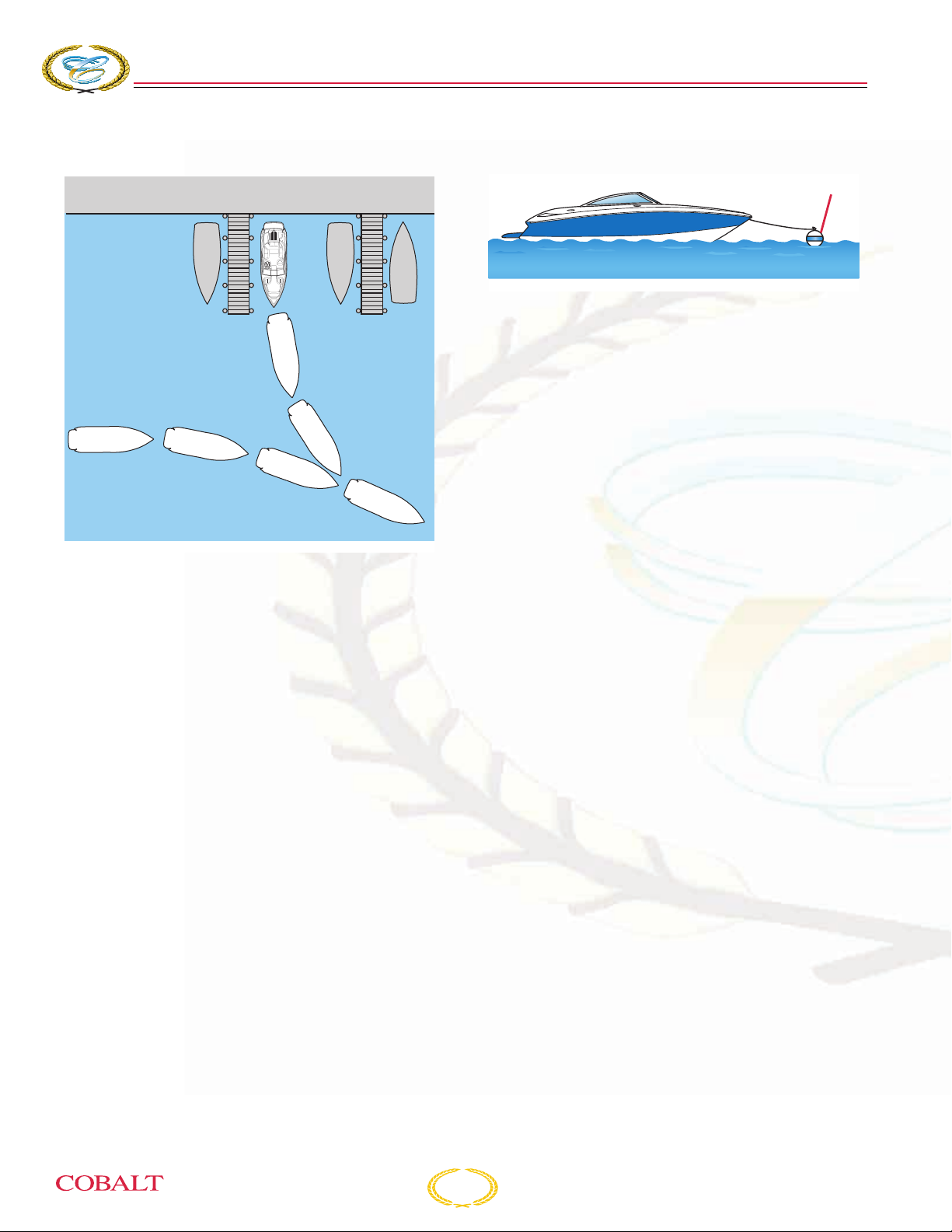
COBALT
276
BOWRIDER
S
ECTION
3
Approaching a Slip
6
1
This maneuver is similar to backing an automobile
into a garage or parking space. When approaching
a slip:
• Have fenders, mooring lines and the crew
ready.
• Turn the boat’s stern toward the slip.
• Shift to REVERSE.
• Maneuver slowly into the slip then shift to
FORWARD. Use your steering wheel and
throttles to align the boat with the slip.
• Once aligned, shift to REVERSE and continue
to back in slowly. Shift into FORWARD when
completely in to stop the movement of the boat.
• Shift to the NEUTRAL position, secure the
mooring lines and stop the engine.
2
5
3
4
COB_0064_A
Approaching a Mooring
1
COB_0065_A
1 – Mooring Buoy
The only buoys you are permitted to moor to are
mooring buoys. Mooring to a navigation buoy or
other navigational aids or regulatory marker is
illegal.
Approach a mooring buoy by heading into the wind
or current. Observe the direction of other boats that
already lie at mooring buoys. Since they are
heading into the wind or current, approach your
buoy at the same heading.
• When you think you can move enough forward
without using your engine, shift to the
NEUTRAL position.
• Have a crew member positioned on the bow
with a hook to retrieve the mooring line. At that
point, the crew member should be guiding your
maneuvers toward the buoy.
• Turn off the engine after the mooring line is
attached to the boat.
Basic Maneuvering
Techniques
Wandering is a characteristic of all deep V-hulls at
slow speed. There is no cure for wandering;
however, a very basic operational technique can be
applied which will minimize this characteristic.
If the steering wheel is moved back and forth to
compensate for wandering, invariably, the situation
will be magnified. If the steering wheel remains in a
centered position, the boat will wander back and
forth slightly; however, the overall course of the
boat will be a straight one.
3-12
276 Owner’s Manual

O
PERATING
I
NFORMATION
Trim
Boat trim while on plane is influenced by three
factors:
1. Load distribution
2. Drive unit trim
3. Trim tab position, if equipped
Determining best boat trim while underway takes
time. It is best to experiment with different drive and
tab trim combinations while taking note of the
condition.
Load Distribution
The performance of your Cobalt boat depends on
load weight and distribution.
Distribute weight evenly, from bow to stern, and
also from port to starboard.
Drive Unit Trim
Trim angle is the angular relationship between the
drive unit and the transom of the boat. Boat trim
while underway greatly affects the performance and
efficiency of your boat. For best results, the boat
should be on plane and trimmed to reduce the
amount of the boat’s hull in the water (known as
wetted surface). With less boat in the water, both
speed and fuel economy increase.
Continuous trim adjustment is required when
operating your boat to maintain maximum
performance and efficiency.
If the drive unit is trimmed in too far (closer to the
boat bottom), speed drops, fuel economy
decreases and the boat may not handle correctly.
However, it does provide better acceleration from a
standstill; and because it forces the bow down,
visibility is improved. If the drive unit is trimmed out
too far (away from the boat bottom), steering torque
may increase, the boat may be difficult to get on
plane and it may bounce.
To use power trim effectively, start with the drive
unit trimmed in. As the boat planes, increase the
angle out. Experience is the best teacher for
understanding proper drive trim.
276 Owner’s Manual
3-13
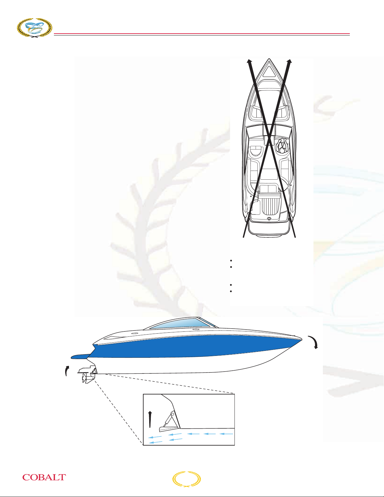
COBALT
A
Trim Tabs
The trim tabs, if equipped, are a separate system in
themselves and are not to be used in lieu of the
drive unit power trim system. Water is deflected
and redirected as the trim tabs are raised and
lowered. This change in the water flow creates
upward pressure under the tabs, and raises the
stern. When the stern raises, the bow is lowered.
Likewise, lowering the port tab will cause the port
stern to raise, making the starboard bow lower.
Using trim tabs in conjunction with the drive trim will
compensate for uneven weight distribution, listing,
water conditions and other factors that cause
inefficient operation. Remember that trim tabs are
trimming the hull, while power trim is trimming the
drive unit.
Some systems may include indicators to show
position of the tabs and drive unit.
276
BOWRIDER
S
ECTION
3
STERN
RISES
WATER IS REDIRECTED
CREATING UPWARD
FORCE AT STERN
PORT TAB LOWERED
PORT STERN RISES
STARBOARD BOW LOWERS
STARBOARD TAB LOWERED
STARBOARD STERN RISES
PORT BOW LOWERS
COB_0067_A
BOW
LOWERS
HULL
COB_0068_
3-14
276 Owner’s Manual
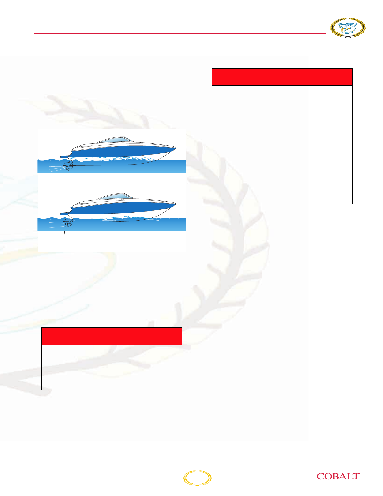
O
PERATING
I
NFORMATION
To adjust boat trim while underway:
1. Before accelerating, make sure both trim tabs
are fully raised.
2. Adjust the trim tabs to achieve a planing
attitude.
3. Use the drive trim to position the propeller path
parallel to the water flow.
UNTRIMMED
PLANING
ATTITUDE
PROP PARALLEL TO WATER FLOW
COB_0069_A
4. Readjust the trim tabs to fine tune attitude.
Operate only one tab at a time and in small
increments. As the tab takes effect, you will
notice it causes the boat to veer off course
slightly. Correct for this as it happens.
5. To prevent the boat from listing, do not move
one tab significantly further down than the other
tab.
A DANGER
Avoid injury or death. Use the trim tabs
slowly to adjust trim. Adjustments are
not immediate. Improper use of the trim
tabs at high speeds can cause an
accident.
High-Speed Operation
A DANGER
Avoid injury, death or property damage.
Maneuverability above 50 mph is
limited. Sudden turns may cause loss of
control. Your Cobalt boat is not
designed for wake jumping. When
crossing another boat’s wake, throttle
back to prevent your boat from leaving
the water. Wake jumping is very
dangerous. It is possible for the boat to
re-enter the water on its side, transom or
bow. You and your passengers could
suffer serious injury. Also, damage to
the boat could take place causing a
hazardous condition.
When operating any boat at high speed, exercise a
great deal of caution. This is particularly true during
turns. Gradual turns can be completed at high
speed by a competent driver, but it must be
emphasized that sudden turns at any speed, and
particularly at high speed, can be especially
dangerous. It is possible to throw passengers from
their seats and even from the boat if caution is not
exercised. Remember, common sense is the rule
for safe boating.
We recommend that you have 10 hours of
experience with the boat before any full throttle
operation. Do not operate your boat until you are
completely experienced with its handling
characteristics. The following are some guidelines
for performance operation.
• Keep bottom of the hull clean and free of
barnacles and other growth. Growth on the hull
can slow the boat down considerably.
• Prepare the boat. Be sure all gear is properly
stowed and compartments are latched.
• Weight distribution affects performance. Keep
weight in the boat to a minimum and evenly
distributed.
276 Owner’s Manual
3-15
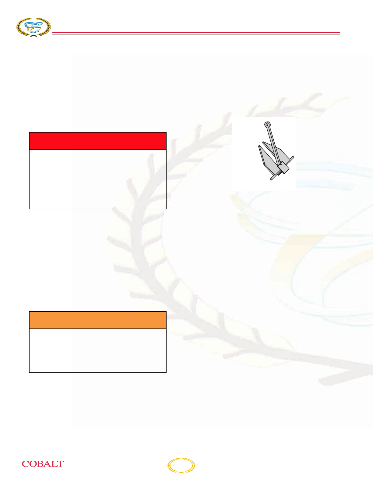
COBALT
276
BOWRIDER
S
ECTION
3
• The propellers should be of the proper pitch to
turn the recommended RPM rating for the
engine with an average boat load. Refer to your
propulsion unit operator’s manual for additional
information.
• Watch the tachometer. Keep the engine within
the full throttle operating range. Refer to the
propulsion unit operator’s manual for full
throttle operating range.
A DANGER
Avoid injury, death or loss of control.
Keep one hand on the steering wheel
and the other on the throttle control at
all times. If the boat begins to operate in
an unsafe way, pull back on the throttle.
Trim the drive unit in at the same time
and maintain control.
High-speed operation on smooth water is very
stable, but quick reactions and adjustments are
needed to maintain control. Know your limits and
stay within them. Keep one hand on the steering
wheel and the other on the throttle; constant
adjustments are necessary for rapidly changing
conditions. Small inputs of throttle, steering and
trim movement are exaggerated at high speeds.
Keep watch well ahead so that you have enough
time to react.
Anchoring
There are many types of anchors available on the
market. The choice of one anchor over another
depends on many factors. An anchor will usually
hold best in a mixture of mud and clay or in hard
sand. A Danforth anchor is recommended for
general boating. For more information on anchors,
contact your authorized Cobalt dealer.
DANFORTH
ANCHOR
KC-1571
The windlass, if equipped, gets its power from the
12V DC system. The windlass can be operated at
the driver’s helm (indicator light must be
illuminated) or from the foredeck. There are
foot-operated switches located under the anchor
locker door.
The windlass system can also be operated
manually. On the anchor locker lid on the foredeck,
you will find a crank. A longer windlass crank is
located in one of the cockpit storage areas or in the
engine compartment bulkhead.
Please consult the operator’s manual supplied with
the windlass system for proper operation of the
system in the electric and manual modes.
A WARNING
Avoid injury, death or swamping. Anchor
from the bow, not from the stern. A
strong current can pull a boat
underwater, anchored by the stern, and
keep it there.
Be sure the anchor is adequate for your boat. Use
caution when anchoring. Look for signs of
underwater pipes or cables. With the engine off,
you have no control of the boat. Water and wind
conditions will affect an anchored boat. Be sure the
anchor will hold before leaving the boat.
The circuit breaker on the battery switch panel
under the port aft seat must be in the ON position
to operate the windlass. When not in use, turn the
circuit breaker to the OFF position.
3-16
276 Owner’s Manual

O
A WARNING
Avoid injury and/or property damage.
• Keep hands, feet, loose clothing and
hair well clear of the winch and
rope/chain during operation.
PERATING
Setting
When the anchor hits bottom, slowly back up the
boat, keeping tension on the line. The anchor line
should be five to seven times the depth of the
water.
Weighing
I
NFORMATION
• Keep clear view of the winch when
operating it.
• Run the boat’s engine while raising or
lowering the anchor. Not only is this a
safety precaution, it also prevents
draining of the batteries.
• DO NOT use the winch as a bollard.
When anchored, secure the anchor
line directly to a bollard or deck cleat.
• Secure the anchor with a rope or
fastener pin when operating the boat
at high speed, in heavy weather or
while transporting.
• Turn the WINDLASS switch off when
the winch is not in use and before
leaving the boat.
• Keep the rope in good condition and
free from twists, knots, heavy
abrasions and salt buildup. In the
event of the rope slipping or jamming,
reverse the direction of the winch and
check the rope for damage.
• Ensure the size and type of chain used
with this switch is compatible with the
rope/chain.
Use caution when anchoring. Look for signs of
underwater pipes or cables. With the engine off,
you have no control of the boat. Water and wind
conditions will affect an anchored boat. Be sure the
anchor will hold before leaving the boat.
Lowering
Bring the boat to a stop with the bow facing into the
wind or current. Lower the anchor. On dash control,
place safety switch in the ON position.
Press and hold the toggle switch down to pay out
sufficient rope/chain to set the anchor.
To weigh (retrieve) the anchor, start the engine and
slowly move forward. Press the toggle switch up
while taking in anchor line as you go. Carefully
retrieve the last meter (36 inches) of rope/chain,
then seat the anchor in the bow fitting. Use snubber
to secure the anchor at all times in case of windlass
clutch failure.
Refer to the windlass operator’s instructions for
additional operating information.
Towing
If seas are rough, it may not be easy to extend the
tow line from one boat to another. In these cases,
use a light throwing line with a weight on one end
and with the heavier towing line secured to it.
Do not attempt to tow a larger or grounded vessel.
Because of the tremendous stress caused by
towing, use a tow line that is rated at least four
times the gross weight of the boat being towed.
Tow ropes must be in good condition, free of any
cuts or abrasions.
Attach the tow line (2) to the bow eye (3) on the
disabled boat. Attach the opposite end of the bridle
only to the stern cleats (1) of the tow boat. Wrap the
bridle with chafing gear where it rubs against the
boat.
Leave at least two boat lengths between the boats
for adequate movement.
A DANGER
Avoid injury, death or property damage.
When towing, only use the bow eye and
stern eyes. DO NOT use deck cleats or
handrails. DO NOT allow anyone to be in
line with the tow rope.
276 Owner’s Manual
3-17
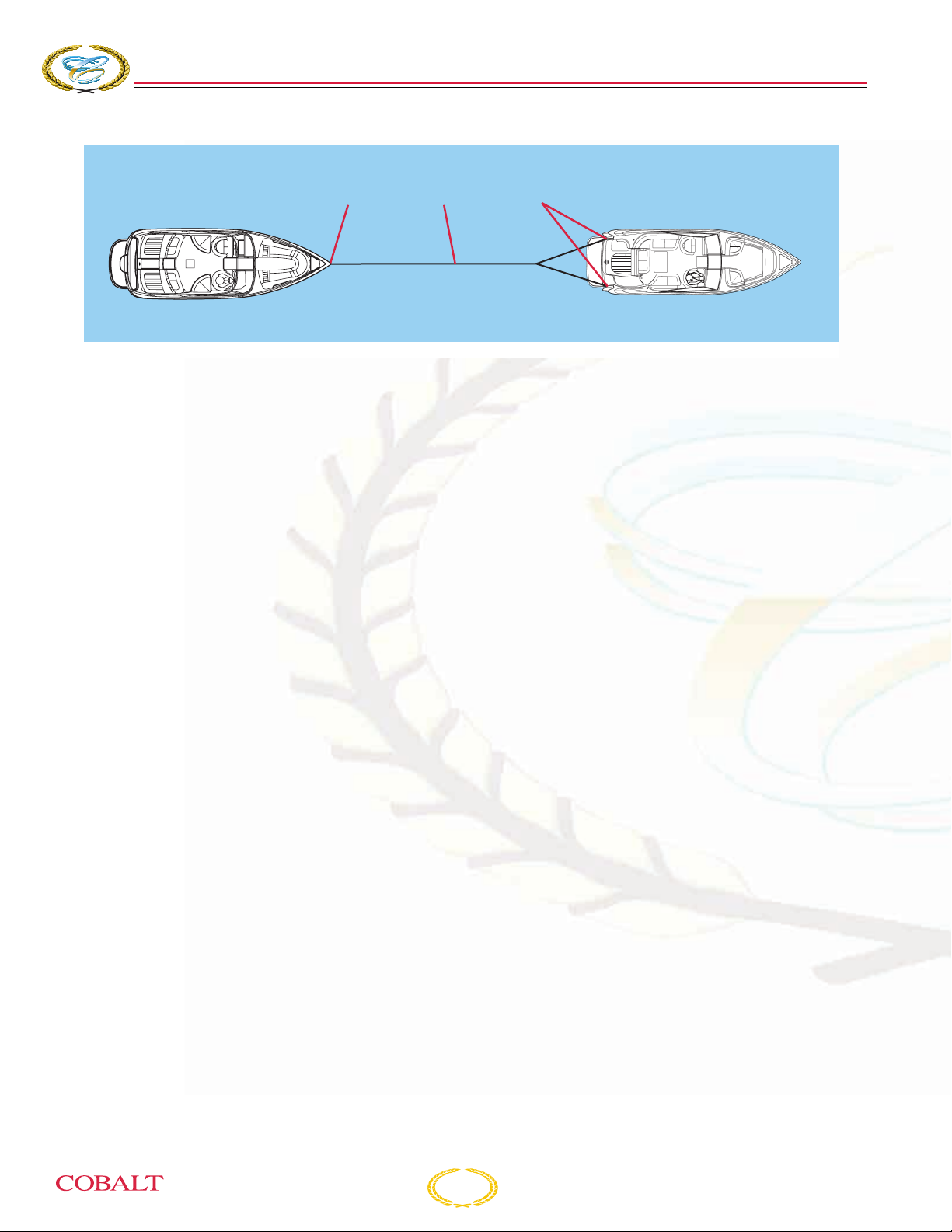
COBALT
276
BOWRIDER
S
ECTION
3
3
Adjust the tow line to match wave action. Keep the
boats on the crest or in the trough of the waves at
the same time. In protected, calm waters, shorten
the line for better handling. Tow at moderate speed,
allowing for adverse wind and wave conditions.
Have the operator of the towed boat steer with you,
if possible.
If you need a tow, or wish to tow another boat, use
great care. The boat structure can be damaged by
excessive pulling strain. You should offer help to a
boat in trouble. However, towing a capsized,
grounded or hull-damaged boat is dangerous. Give
assistance to the occupants, then call the proper
authorities.
2
1
Environmental Considerations
Using your boat in different environments requires
special operating considerations.
Salt Water
During long periods of mooring, if possible, tilt the
propulsion unit drives out of the water – except in
freezing temperatures. Refer to the drive system
owner’s manual for more information on saltwater
operation and protection.
Freshwater flushing of the engine is recommended
after operating in salt, polluted or brackish water.
Refer to your engine operator’s manual for
additional information.
COB_0003_A
Freezing Temperatures
When boating in temperatures below freezing, keep
the propulsion unit drives tilted down (submerged)
at all times. This will help prevent damage from
freezing.
Upon removing your Cobalt boat from the water,
leave the drive unit in the vertical position until
cooling system has drained.
Refer to your propulsion unit operator’s manual for
additional information regarding winterization.
3-18
276 Owner’s Manual

O
PERATING
Entertainment System
Your Cobalt boat is equipped with an AM-FM CD
player, iPod™/MP3 Port and may have been
accessorized to enhance its fidelity. To operate your
entertainment system, you must first supply power
to the unit(s). Make sure the battery switch is on
and the ignition switch is set on “ACC.” If your boat
is equipped with a Power Distribution Panel, the
switches for the entertainment system components
must be turned to ON before operation. For
additional operating information, refer to the
operator’s manual for your stereo and accessories
supplied to you in your owner’s packet. For a list of
what is standard, or is available for your
entertainment system, refer to Standard
Equipment or Optional Equipment in this section.
The audio speakers in your Cobalt are designed to
deliver maximum fidelity in a marine environment.
The speakers can be damaged if struck by a sharp
object or if the moving elements are restricted from
movement. Do not store or place any sharp objects
near the speakers, or restrict the element
movement.
I
NFORMATION
276 Owner’s Manual
3-19

COBALT
276
BOWRIDER
S
ECTION
3
COBALT INSTRUMENTATION
SYSTEM
Your Cobalt boat is equipped with instruments
manufactured by Medallion Instrumentation
Systems. Each instrument has been manufactured
in an ISO 9001-2000 registered facility, built to
stringent standards and has passed a
comprehensive quality control procedure prior to
shipment. Each instrument is backed by a limited
lifetime warranty.
The Cobalt Instrument System: Each gauge
system consists of a single Data Interface Gauge
(DIG) and several auxiliary gauges. The Data
Interface Gauge collects information from the CAN
bus and analog inputs and drives the auxiliary
gauges via a low-speed data bus. The auxiliary
gauges receive power from the Data Interface
Gauge. The backlight of all the gauges is powered
on a connector terminal, not associated with any
data bus.
Instrument Fogging: The instruments are
designed to be “fog resistant.” There are small
vents in their cases to allow trapped moisture to
escape. Occasionally moist air may be drawn into
the vents when the air inside the gauge cools down,
after the instrument is turned off. The morning sun
can draw this moisture up against the lens, causing
fogging. Turning on the instrument with the
instrument light “ON” will speed up moisture
removal. Your Cobalt instruments are built to
withstand the harsh marine environment, and
fogging will not harm them.
Radio Transmissions: Some interference (erratic
operation) may be noticed on tachometers or
synchronizers during radio transmissions. This will
not damage the instrument or affect its accuracy.
For twin-engine applications, data for both engines
is on the CAN (P) bus attached to the Starboard
Master DIG to enable this system. The Master
(Starboard) and the Port DIGs are unique, distinct
gauges and are defined by the software
programmed into each gauge.
Tachometers: Most tachometers have a tolerance
of 2% of full scale (120 RPM on a 6000 RPM tach).
In a twin-engine application, this could be a 240
RPM difference between each tach reading when
the engines are in sync. The tachometers will read
zero when the key is turned on, without the engine
running. The tach may display a reading when the
key is turned off.
Trim Gauges: Trim gauges are calibrated to be the
most accurate and useful in the engine down or
“trim” range. The gauge may not read full “up” in
some cases. This is not unusual, nor does it
indicate a problem with either the trim sender or the
gauge.
Fuel Gauges: Fuel gauges may “bounce” from fuel
sloshing in the tank. This does not necessarily
indicate a problem with the gauge or sender.
3-20
276 Owner’s Manual
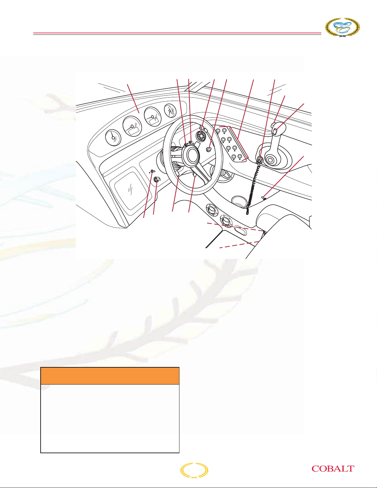
O
PERATING
HELM AND INSTRUMENTATION
2
1
3
I
NFORMATION
45 6 7
8
9
10
15
16
Your Cobalt boat helm will monitor and provide
operation of the boat’s functions. The gauges are
illuminated for night operation. When the switches
are activated, the LEDs will illuminate if the switch
is ON.
On occasion, a small fluctuation in a gauge reading
is not unusual. If an instrument reading is outside
the normal or recommended ranges, determine the
cause or see your authorized Cobalt dealer.
Refer to the engine operator’s manual for normal
recommended ranges.
A WARNING
Avoid the risk of injury, death or
equipment damage. If the safety of you
or others depends on running the
engine during an abnormal condition,
make the right decision on saving
equipment or lives. Do not jeopardize
the safety of you or others to protect
your boat.
1314
11
12
COB_0278_A
1. GAUGE CLUSTER
General Gauge Operation
System Architecture
Each gauge system consists of two Data Interface
Gauges and several auxiliary/slave gauges. The
Data Interface Gauge collects information from the
CAN bus and analog inputs, and drives the
auxiliary gauges via a low-speed data bus. The
auxiliary gauges receive power from the Data
Interface Gauge. The backlight of all the gauges is
powered on a connector terminal, not associated
with any data bus.
System Start-up
At key on, all the gauges will perform a pointer
reset (goes to zero or minimum reading). The Data
Interface Gauge speedometer and the tachometer
will perform an LCD all-segments-on test. Once
these initializations are complete, the gauges will
begin non start-up operation.
276 Owner’s Manual
3-21

COBALT
276
BOWRIDER
S
ECTION
3
System Shutdown
At key off, all gauge pointers will return to “zero” or
minimum value. The Data Interface Gauges will
turn their LCDs off and shut power off to the
auxiliary gauge.
Speedometer and Tachometer LCD Operation
Both gauges have buttons on the bottom of the
gauges to scroll through the information available in
the LCD. The right button will advance the screens
forward and the left button back.
Available Information in Speedometer
(Standard or GPS Package)
Hour Meter - Run time calculated by the engine’s
computer.
Tachometer - Digital readout of engine RPM.
Miles Per Hour - Digital readout of the vessel’s
speed through the water (MPH or KMH).
Oil Pressure - Digital readout of engine oil
pressure (PSI or KPA).
Engine Temperature - Digital readout of the
engine temperature (in degrees F/C).
Heading - Will display 8 major compass headings
(N, S, E, W, NE, NW, SE, SW).
Available Information in Tachometer
(Standard or GPS Package)
Hour Meter - Run time calculated by the engine’s
computer.
Tachometer - Digital readout of engine RPM.
Miles Per Hour - Digital readout of the vessel’s
speed through the water (Merc. only) (in degrees
F/C).
Oil Pressure - Digital readout of engine oil
pressure (PSI or KPA).
Engine Temperature - Digital readout of the
engine temperature (in degrees F/C).
Block Pressure - Digital readout of the water
pressure inside the block (not available on Volvo
engines).
Battery Voltage - Digital readout of battery voltage.
Fuel Level/Fuel Burn Rate - Amount of fuel in fuel
tank in percentage and the rate the fuel is being
burned (in GPH or LPH).
Block Pressure - Digital readout of the water
pressure inside the block (not available on Volvo
engines).
Battery Voltage - Digital readout of battery voltage.
Fuel Level/Fuel Burn Rate - Amount of fuel in fuel
tank in percentage and the rate the fuel is being
burned (in GPH or LPH).
Trim Angle - Digital readout of the drive angle with
zero degrees being straight down.
Rudder Angle - Slide bar showing the position of
the drive (when option is purchased).
Water Depth - Digital readout of water depth (ft or
M).
Air Temperature - Outside air temperature
(in degrees F/C).
Lake Temperature - Temperature of lake water
(in degrees F/C).
Trim Angle - Digital readout of the drive angle with
zero degrees being straight down.
Rudder Angle - Slide bar showing the position of
the drive (when option is purchased/Merc only).
Alarms
Alarm Overview
Alarm information will be displayed as described
below. This system does not allow for
acknowledgement and de-emphasis of the alarms
in the various display modes.
Low Block Pressure Alarm
Appearance - When the low block pressure
message is received, the LCD display shows “W P”
flashing.
Low Drive Lube Alarm
Appearance - When the Low Drive Lube Alarm is
received, the LCD display shows “
L L” flashing.
3-22
276 Owner’s Manual

O
PERATING
I
NFORMATION
Check Engine Alarm
Appearance - When the Check Engine Alarm is
received, the LCD display shows “C E” flashing.
Guardian Active Alarm
Appearance - When the Guardian Active Alarm is
received, the LCD display shows “C E” flashing.
Helm Fault Alarm
Appearance - When the Helm Fault Alarm is
received, the LCD display shows “H F” flashing.
2. NAV. LIGHTS - NAV/ANC “Lights” - The
NAV/ANC is a three-position switch which activates
the navigational (running) lights and the anchor
light. After installing the light, press the switch
toward the “NAV.” Press the switch toward the
“ANC” and the anchoring/mooring light (360° white)
will illuminate.
NOTICE: Operate the boat
between sunset and sunrise
using your navigational lights.
Navigational lights are legally
required to indicate direction
and right-of-way at night.
Navigational Lights - You must use your
navigational lights (running lights) when operating
your Cobalt boat between sunset and sunrise, and
when daytime visibility is limited. Also, check with
the local authorities before operating your boat for
other requirements concerning the use of
navigational lights.
The navigational lights are identified by a red light
on the port side of the vessel, and a green light on
the starboard side.
Anchor/Mooring Light - All boats at anchor or
moored must display a proper white anchor light.
The anchor light (all-around light) is the white light
located aft of the cockpit. The anchor light must be
visible from 360° and will remain on when operating
the navigational lights.
3. ENGINE HATCH - This switch operates the
electric motor box assembly. Do not continue to
operate the switch when the motor box is closed or
fully open. Lower the motor box support after the
motor box is opened. Be sure to return the support
to its stowed position before lowering the box.
4. STEREO REMOTE CONTROL (standard on
dash, transom mount – optional) - This panel
provides remote control of the stereo system from
the helm.
5. HEATER (Optional) - This switch operates the
optional cockpit heater blower. It is a four-position
switch: OFF/LOW/MEDIUM/HIGH. Temperature
can be controlled by the switch and by adjusting the
louvered vents. The cockpit heater will only be
effective (warm enough) when the engine is
running at normal operating temperature.
6. SWITCH PANEL
HORN - This switch activates the horn. Press the
switch to activate.
BILGE PUMP - This switch manually controls the
bilge pump.
DOCKING LIGHTS (Optional) - This switch
operates the docking lights.
Docking lights are to be used for docking only. It is
illegal to use your docking lights while cruising.
INTERIOR LIGHTS - This switch provides
illumination within the cockpit area.
STORAGE and ENGINE COMPARTMENT
LIGHTS - This switch provides illumination within
the storage areas and engine compartment.
CAPTAIN’S CALL (Optional) - This switch
determines the routing of the engine exhaust. In the
ON position, engine exhaust is routed through the
thru-hull pipes. This position produces the most
engine power, but is not acceptable near shore or
on inland lakes and rivers.
In the OFF position, engine exhaust is routed
through the hub of the propeller. This position
releases the exhaust underwater, providing a
quieter engine sound.
276 Owner’s Manual
3-23

COBALT
Be sure to check local regulations regarding noise
restrictions before operating this system.
276
BOWRIDER
CAUTION
S
ECTION
3
Avoid damage to the exhaust system.
DO NOT switch the routing of the
exhaust above 3,000 RPM.
PLATFORM LIGHTS - This switch provides
illumination within the platform area.
ACC - This switch is available to operate switched
accessory items.
NOTICE: DO NOT connect an
accessory drawing more than 10
amps to the accessory switch. A
hazardous situation or damage
to the electrical system can
occur.
7. IGNITION SAFETY SWITCH
A WARNING
Avoid injury, death or damage to
equipment. Do not allow your boat to be
operated without the proper use of the
ignition safety switch and lanyard.
1
2
3
COB_0042_A
1 – Ignition Safety Switch
2– Lanyard
3 – Hook
Your Cobalt boat is equipped with an ignition safety
switch located on the lower lip of the helm. The
ignition safety switch and lanyard will stop the
engine in case of an emergency. Attach the lanyard
to the boat operator whenever the engine is
running, but be aware there will be a loss of boat
control if the switch is activated. If the operator is
thrown from the seat or moves too far from the
helm, the lanyard will become disconnected from
the ignition safety switch, shutting off the engine.
3-24
276 Owner’s Manual

A DANGER
O
PERATING
I
NFORMATION
Remote Control
Avoid injury or death. Attach the ignition
safety switch lanyard to the operator
before starting the engine. This will
prevent the boat from becoming a
runaway if the operator is accidentally
thrown away from the helm. The ignition
safety switch can only be effective when
it is in good working condition. Observe
the following:
• Do not remove or modify the ignition
safety switch and/or lanyard.
• The lanyard must be free from
obstructions that could interfere with
its operation.
• DO NOT operate the boat if the ignition
safety switch does not function
properly.
• Attach the ignition safety switch
lanyard to a secure place on your
clothing, your arm or leg while
operating.
• DO NOT attach the lanyard to clothing
that could tear loose. DO NOT route
the lanyard where it could become
entangled, preventing it from
functioning.
A DANGER
Avoid injury or death. Make sure all
shift/throttle hardware and cables are
regularly inspected and maintained.
Improperly maintained controls are
hazardous and may cause sudden loss
of control.
NOTICE: Do not use the shift
levers when the engines are not
running. Do not shift too quickly
from FORWARD to REVERSE.
Damage to the engine and
transmission can result. When
shifting from FORWARD to
REVERSE, pause in the
NEUTRAL position until the
engine is at idle speed and the
boat has slowed. When shifting
from NEUTRAL to FORWARD or
REVERSE, shift briskly and
decisively.
Your Cobalt boat is equipped with a safety switch
for “start-in neutral-only” operation. The shift lever
must be in the NEUTRAL position before
attempting to start the engine.
• Avoid accidentally pulling the lanyard
during normal operation. Loss of
engine power means loss of most
steering control. Also, without engine
power, the boat could slow rapidly.
This could cause occupants and
objects in the boat to be thrown
forward.
276 Owner’s Manual
The following information relates to the general
description of your controls. Refer to the engine
operator’s manual or the control operator’s manual
for specific use.
8. SHIFT/THROTTLE LEVER - Your control is a
single lever which operates as both a gear shifter
and a throttle. The control has a detent to position
NEUTRAL for starting.
3-25

COBALT
276
BOWRIDER
S
ECTION
3
To shift, move the lever to FORWARD or pull it back
for REVERSE. Advancing the lever beyond the shift
position increases engine RPM. DO NOT shift
when the engine is not running. Refer to the engine
operator’s manual for more information and
functions of the remote control.
9. DRIVE UNIT TRIM SWITCH - This switch
controls the trim angle of the drive unit and will
maximize the performance and ride of the boat. If
combined with the optional trim tabs, enhancement
to your performance and ride can be achieved.
10. WATER PRESSURE - This switch activates the
water pressure pump. Water pressure is required
for the head to flush.
11. TRANSOM SPEAKER SWITCH
12. CIRCUIT BREAKERS - These are the breakers
for the helm labeled protected device. These
breakers will activate if overloaded, and cut power
to the switch. To restore power, turn off the device,
push the breaker button in and release. If the button
continues to pop out when the device is used, see
your authorized Cobalt dealer. Your boat may not
be equipped with all of these features or options.
16. BILGE BLOWER - This switch activates the
engine compartment ventilation blower to remove
explosive fumes from the area. The blower must be
operated for a minimum of four minutes each time
before starting the engine. In addition, the blower
should be operated continuously when at idle or
running at slow speeds. The LED will illuminate if
the switch is ON.
13. 12-VOLT ACCESSORY POWER
RECEPTACLE - Your Cobalt boat is equipped with
a 12-volt accessory power receptacle. The
receptacle provides electricity to operate 12V DC
accessory items. Limit the accessory to 10 amps.
14. TILT STEERING RELEASE LEVER - This lever
adjusts the steering wheel angle to a comfortable
position when the boat is not moving.
15. IGNITION SWITCH - This switch starts the
engine. It also supplies accessory power when
turned to the left.
A WARNING
Avoid injury, death or explosion.
• Check engine compartment for
gasoline or vapors.
• Operate blower for four minutes.
• Verify blower operation.
• Run blower below cruising speed.
3-26
276 Owner’s Manual

STANDARD EQUIPMENT
O
PERATING
I
NFORMATION
FEATURE
Dash and Instrumentation
Accessory Power Plug - 12 Volt
Black Leather/Stainless Steering Wheel
Compass
Depth & Water/Air Temp Gauge Pkg.
Hour Meter
Wood Dash/Trim Package
Stereo
AM-FM iPod Stereo w/6 speakers
iPod/MP3 Port
Stereo Remote, Dash
Exterior
Aluminum Windshield w/Stainless Steel Cap
Anchor Locker
Bow Scuff Plate, Stainless Steel
Midship Cleats
Motor Box Actuator
Swim Platform, Extended w/Ladder
FEATURE
Interior
Aft Sunpad w/Adjustable Backrest
Aft Sunpad w/Walk-Thru Transom
Bow Walk-Thru Doors
Double Wide Helm Seat
Porta Potti
Removable Bow and Cockpit Carpets
Sink Console (Head area)
Trash Receptacle
Structure / Safety / Performance
10/5/3 Year Warranty Protection
Battery Switch - Single
Composite Floor
Composite Transom
Fiberglass Cockpit Liner
Fiberglass Stringer System
Fire Extinguisher, Manual
Ignition Safety Switch
Kevlar™ Reinforced Hull
Stainless Steel Windshield Braces
Thru-Prop Exhaust
276 Owner’s Manual
3-27

COBALT
276
OPTIONAL EQUIPMENT
BOWRIDER
S
ECTION
3
FEATURE
Canvas
Bimini Top
Bow Tonneau Cover
Cockpit Tonneau Cover
Mooring Cover
Dash and Instrumentation
GPS Unit (in-dash)
Rudder Indicator
Stereo
CD Changer (6 disc)
Premium Sound System
Premium Sound System w/transom speakers
Satellite Radio System w/6 month service
Stereo Remote, Transom
Exterior
Docking Lights, Stainless Steel
Fender Clips w/Line (4)
Flagpole w/Flag
Portal Light - 1 (Head Compartment w/screen)
Retractable Dock Lines
Stainless Steel Arch w/Bimini Top
Swim Platform Transom Lighting
Teak Swim Platform & Aft Walk-Thru
Transom Shower
Transom Tilt Switch
Underwater Lighting
FEATURE
Interior
Aft Walk-Thru Carpet
Air Compressor w/Holder
Bow Cushion Insert
Carpet, Alternative, Sisal Seagrass (Sand & Terra)
Carpet, Waterweave (Sand & Terra)
Cockpit Heater
Dinette Table
Electric Porcelain Head
Electric Porcelain Head w/Macerator
Faucet, Cockpit Sink
Gray Water System
Pump-Out Porta Potti
Pump-Out Porta Potti w/Macerator
Remote Courtesy Lights w/Key Fob
Stainless Steel Foot Tread
Structure / Safety / Performance
Battery Switch - Dual
Captain’s Call Plus (w/Mufflers)
CE Requirements w/Auto Fire Extinguisher
Cruise Control, Perfect Pass w/GPS
Fire Extinguisher, Automatic System
Tool Kit
Trim Tabs
Windlass w/Line, Chain & Anchor
3-28
276 Owner’s Manual
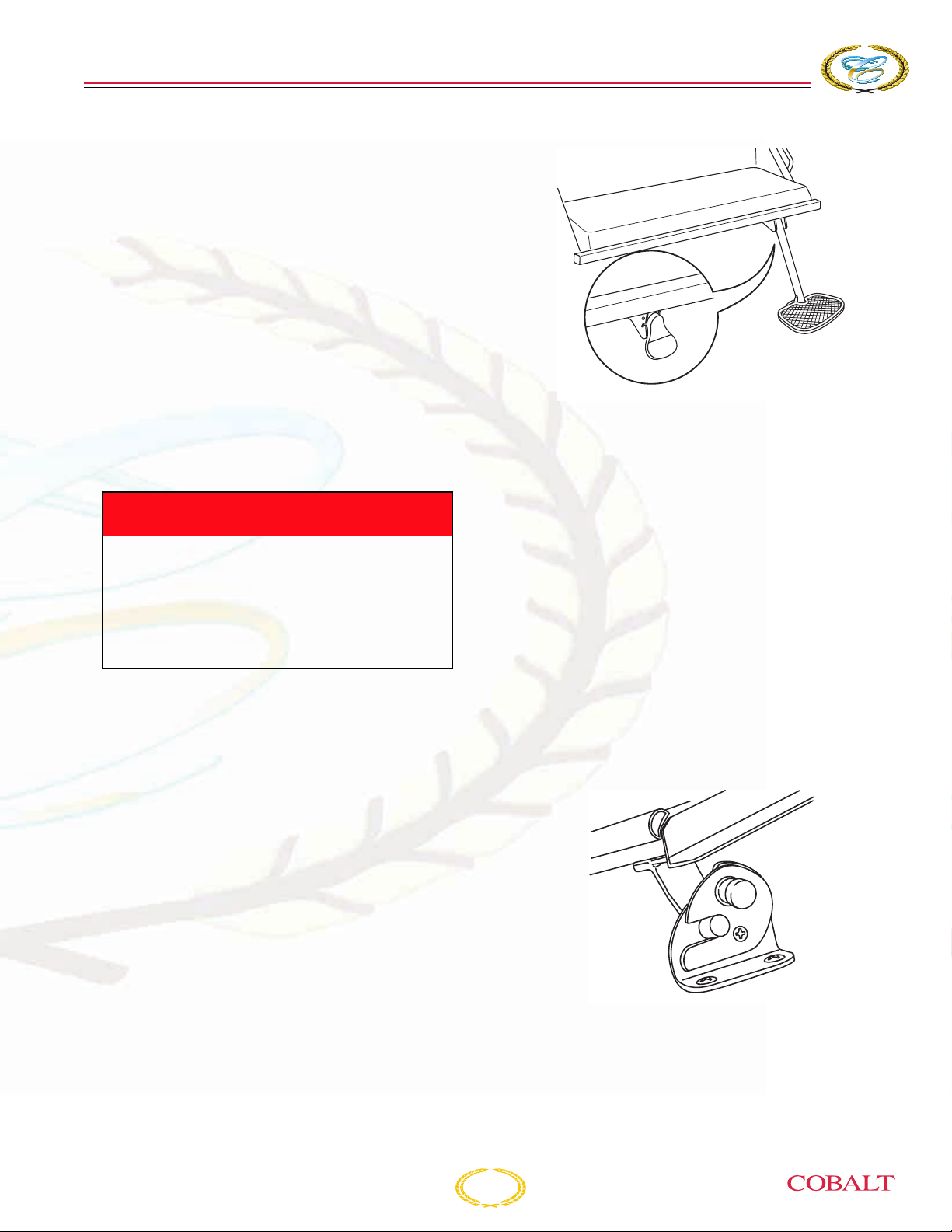
O
PERATING
CAPTAIN’S CHAIR
ADJUSTMENTS AND
OPERATION
Your captain’s chair has a flip-up bolster position for
greater visibility and maneuverability while docking.
You can sit on the raised cushion or stand in front of
the cushion.
Standing while driving your boat should only be
done while maneuvering at an idle by an
experienced driver.
The captain’s chair can be adjusted fore and aft.
Pull the lever on the side seat and slide the seat
fore or aft. Make sure the lever and seat are rested
in their detents before getting underway.
I
NFORMATION
COB_0279_A
VOLVO PENTA OCEAN
SERIES OUTDRIVE
A DANGER
Avoid potential injury or ejection of
occupants. Do not stand while driving
above an engine idle and make sure all
passengers are seated and seats are in
a locked/secured position when the boat
is underway.
BOARDING LADDER
Lift up to release the ladder and telescope to full
length. Lift ladder to retract and stow. Use caution
when stowing the ladder to prevent pinching
fingers.
Make sure there is no one in the area behind the
boat and the boarding ladder is properly stowed
before starting the engine and engaging the shift
mechanism.
Your boat may be equipped with an Ocean Series
Outdrive from Volvo Penta. In addition to a
composite outdrive, there is a Neutra-Salt switch
located in the helm area of your Cobalt boat.
Please refer to the Neutra-Salt Operator’s Manual
located in your boat bag for operating information.
WINDSHIELD HOOK
To open the windshield make sure the vertical slots
in the mechanism are aligned. Swing the
windshield open until the windshield post falls into
the vertical slots and the mechanism locks.
276 Owner’s Manual
COB_0095_A
To close the windshield, release the locking
mechanism by pulling the forward-facing button.
Swing the windshield into place.
3-29
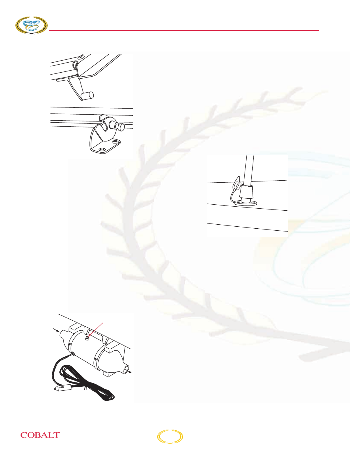
COBALT
276
COB_0096_A
BOWRIDER
COCKPIT DINETTE TABLE OPTIONAL
S
ECTION
A high-volume air compressor is conveniently
located in the starboard aft walk-thru storage
compartment to inflate your favorite water toys.
Plug into the accessory receptacle on the dash or
in the air compressor area.
Avoid direct exposure to water and keep stowed
when not in use.
3
ANCHOR LIGHT
To install anchor light insert pole into socket and
turn clockwise until it locks into place.
Remove the j-shaped table leg from the storage
area. Slide the leg into its mounting support. Slide
the table top onto the leg. If your table top has a
lever, tighten the lever.
BOW CUSHION INSERTS OPTIONAL
The bow area can be converted into a sun deck by
placing the bow cushion insert. Position inserts to
create the sun deck.
AIR COMPRESSOR
Switch
Air Flow
COB_0097_A
Cap the anchor light socket when the anchor light is
removed.
BATTERY SWITCH
The single and/or optional dual battery switch
provides isolation and positive disconnect from the
battery or batteries to protect against tampering,
electrical fire hazards and battery rundown. Battery
selection should be done when the engine is off
(alternate battery usage daily). Switch to the
“primary,” “secondary” or both batteries. Under
normal conditions, the switch should be in the ON
position for one battery rather than the ON position
for both batteries. This will keep one battery in
reserve should the other fail. You can operate the
boat with the switch in the “both” position, but this is
not recommended for extended periods. In the OFF
position, the boat will be isolated from the batteries,
except for the automatic bilge pump.
COB_0101_A
3-30
276 Owner’s Manual
O
PERATING
I
NFORMATION
NOTICE: The purpose of dual
batteries is to keep one as a
spare. In the “both” position,
you essentially have one larger
battery and if a failure should
occur with the electrical
systems or either battery, both
batteries will end up discharged.
WATER SYSTEM
If your Cobalt boat is equipped with a transom
shower (optional), the system allows for potable
(drinkable) water to be stored onboard for the
transom shower. Refer to Section 1,
Specifications, for the capacity of the water
system.
The system is operated by a 12V DC water pump
located in the engine compartment. It is necessary
for the 12V DC system to be energized and the
WATER PRESSURE switch to be turned on to
operate the water system. The water pump works
on demand. It will not automatically shut off when
the freshwater tank is empty.
A WARNING
CARBON MONOXIDE POISONING OR
ROTATING PARTS HAZARD
Poisonous CO gases are present at the
rear of the craft when the engine is
running. Exposure to CO gases can
cause death or serious injury. A rotating
propeller can cut or entangle causing
death or serious injury. DO NOT use the
swim/boarding platform when the
engine is running.
MARINE TOILET (HEAD) AND
MACERATOR - OPTIONAL
Instructions
Before operating the head for the first time, refer to
the marine toilet owner’s manual in your owner’s
packet.
NOTICE: Overboard discharge
of waste water should only be
used in approved areas. It is
your responsibility to comply
with local regulations regarding
the discharge of waste. You
could be fined if your boat has
an operable overboard
discharge system.
To avoid a fine, remove the handle of the seacock
(in the CLOSED position) or disable the system by
other means.
Manually Operated Head
1. Open the inlet water seacock.
2. Pump the floor pedal 2-4 times to fill the bowl
with water.
3. To flush, depress the foot pedal and operate
flush handle next to head at the same time.
Operate handle until all waste is removed.
To empty the bowl of excess water, operate flush
button until water level decreases to desired level.
The marine toilet (head) allows you to hold the
waste in a holding tank. The waste can then be
pumped out through a deck plate fitting marked
“WASTE.”
Electrically Operated Head
To clean the water tank, refer to Section 6, Water
Systems.
Consult your authorized Cobalt dealer for
winterization requirements.
276 Owner’s Manual
CAUTION
Avoid damage to the waste system. Do
not flush into a full holding tank.
1. Open the inlet water seacock below the cabin
floor.
2. If overboard discharge is to be used, make sure
the “Y” valve is in the overboard position.
3-31
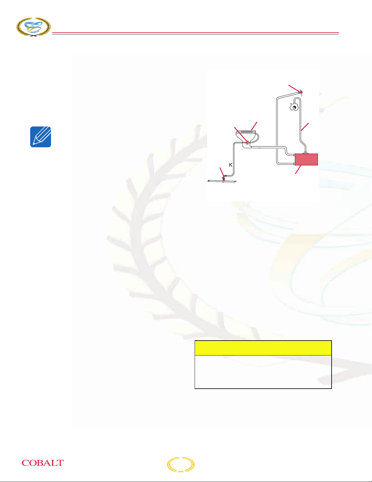
COBALT
276
BOWRIDER
S
ECTION
3
3. To charge the head, depress the foot pedal on
the lower left side of the bowl, and push the
flush button. Release the flush button after the
bowl is moistened, and then pump the floor
pedal 2-4 times to fill the bowl with water.
4. To flush, depress the foot pedal and push the
flush button at the same time - hold until all
waste is removed.
NOTICE: To empty the bowl of
excess water, operate flush
button until water level
decreases to desired level.
The marine toilet (head) allows you to hold the
waste in a holding tank. The waste can then be
pumped out through a deck plate fitting marked
“WASTE.”
The optional macerator system allows the
discharging of waste water directly overboard. For
additional operating information, refer to the
macerator operator’s manual.
If your Cobalt boat is equipped with an
electronically operated head (marine toilet) and
waste containment system, the head draws
seawater in through the hull to flush waste water
from the marine toilet.
The toilet pumps the waste water into a holding
tank.
Your boat is fitted with a waste holding tank. It is
emptied through the deck plate fitting marked
“WASTE.” Waste is pumped from the head through
a sanitary waste hose to the top portion of the tank.
A sanitary waste hose is attached to the bottom of
the tank, and runs to the dockside pump-out plate.
An overboard vent keeps the tank at atmospheric
pressure regardless of waste levels.
All the components of the waste system are made
of materials specially formulated to prevent odor
permeation. It is strongly recommended you
regularly add chemical to your tank by flushing it
through the head. The chemical helps to control
odor and break down the waste. Follow the
manufacturer’s instructions on the chemical before
using.
Waste Disposal
4
2
3
1
6
1 – Seacock
2– Manual Hand Pump
3– Head
4 – Waste Dockside Pump-out Fitting
5– Vent
6 – Holding Tank
Dockside Pump-out - This system directs all
waste to the holding tank. To clear the tank, you will
need to use the dockside pump-out services
provided at marinas or other facilities. To empty the
tank, a suction hose is connected to the “WASTE”
pump-out plate and to the dockside pump. The
WASTE pump-out plate is always located at a “high
point” on the boat. For the WASTE pump-out
connection, refer to Section 4, Water/Plumbing.
5
COB_0190_A
Macerator Pump
CAUTION
Avoid damaging the macerator unit. Do
not run the macerator dry. Running it
when there is no waste will shorten the
life of the system.
A waste tank level monitor is installed to provide a
visual indication of the amount of waste in the tank.
3-32
276 Owner’s Manual

O
PERATING
I
NFORMATION
COCKPIT HEATER OPTIONAL
The optional cockpit heater is activated by a
two-way switch. Temperature can be controlled by
2
adjusting the louvered vents. The cockpit heater will
only be effective (warm enough) when the engine is
running at normal operating temperature.
1
3
COB_0189_A
1 – Thru-Hull Fitting
2 – Macerator Pump
3 – “Y” Valve
The optional macerator system allows the
discharging of waste water directly overboard.
Refer to Section 4, Water/Plumbing for component
location. For additional operating information, refer
to the macerator operator’s manual supplied with
your Cobalt boat.
A “Y” valve is installed between the pump-out plate
and the macerator thru-hull fitting. The macerator
pump is located between the “Y” valve and the
macerator thru-hull fitting. In this configuration all
waste is flushed from the head to the holding tank.
The “Y” valve permits you to use the dockside
pump-out feature, or to use the macerator to pump
the waste from the holding tank overboard.
BOW TONNEAU COVER OPTIONAL
Follow these procedures to attach the bow tonneau
cover:
1. Open walk-thru doors.
2. Starting at bow, slip bow opening over bow,
work aft, and snap the cover to the boat.
3. Close windshield center door and snap the
canvas to the underside of the windshield.
4. Install the adjustable tonneau cover support
pole. Make sure the pole is perpendicular to the
floor and adjust to “tent” the cover.
5. Walk-thru doors may be closed if desired.
Do not use bow tonneau cover for extended
storage. It is not designed for storage, but can be
used for overnight storage or trailering.
NOTICE: Always double-check
snaps are secure.
To pump out the holding tank using the macerator
pump:
1. Move the “Y” valve lever to the DOWN or
OVERBOARD position.
2. Activate the macerator pump by turning its
switch on.
3. Turn macerator pump off after the pump-out is
complete.
If your boat is equipped with a tank level monitor,
the tank level monitor will illuminate the indicator
lights to monitor the tank level.
276 Owner’s Manual
COCKPIT TONNEAU COVER OPTIONAL
Follow these directions for the cockpit tonneau
cover.
1. Unroll the cover and snap to the deck, starting
at the center of the windshield. Snap to the
forward outside edge of the windshield only.
2. Install tonneau support pole(s) to underside of
the cover (just in front of rear seat) with snap
and adjust pole to approximate height of
windshield. Some models have two support
poles. Make sure the poles are perpendicular to
the floor and adjust to “tent” the cover.
3-33

COBALT
276
BOWRIDER
S
ECTION
3
3. Pull elastic cords over discs on transom,
starting in the center and working outboard (you
may have to readjust the support poles for
proper fit).
4. Continue snapping up the sides.
5. The walk-thru doors may be closed if desired.
Do not use cockpit tonneau cover for extended
storage. It is not designed for storage, but can be
used for overnight storage or trailering.
NOTICE: Always double-check
snaps are secure.
BOW TONNEAU
(BOW RIDERS ONLY)
COCKPIT
TONNEAU
COBALT
COB_0138_A
SKI TOW PYLON REMOVABLE
Remove ski pylon from the port, cockpit storage
compartment by pulling the lock button outward
and opening the hold-down bracket.
To i n s ta l l :
Lift pylon base cover on swim platform. Push pylon
down and rotate 1/4 turn clockwise to lock in place.
Make sure pylon is secure before use.
To r e m ov e :
• Pull up and rotate pylon 1/4 turn
counterclockwise to remove.
• Close base cover and return pylon back to its
hold-down bracket. Make sure hold-down
bracket is secure.
A DANGER
To avoid injury or death, do not overload
the pylon or use it for anything other
than water sports. The ski tow pylon
maximum load is 1,000 lbs (454 kg).
BIMINI TOP - OPTIONAL
1. Remove the stainless adjustable arms from the
storage area.
2. Unfold the top and install the stainless
adjustable arms (tensioners) into the
quick-disconnect fittings on the deck, forward of
the windshield. Secure the forward arms to the
forward cross members with the pins.
3. Tighten the bimini by twisting the tensioners.
Do not trailer with the bimini top up. Store and
trailer the bimini top in the stowed position, in its
canvas boot.
NOTICE: To prevent damage to
the motor box, remove pylon
before opening.
SS ARCH WITH BIMINI
INSTRUCTIONS - OPTIONAL
To set up bimini from the stored position:
1. Unzip the canvas boot from the bimini and arch.
2. Zip the aft edge of the bimini to the forward
tubing of the arch.
3. Install two forward support bars and tighten the
bimini by twisting the tensioners.
3-34
276 Owner’s Manual
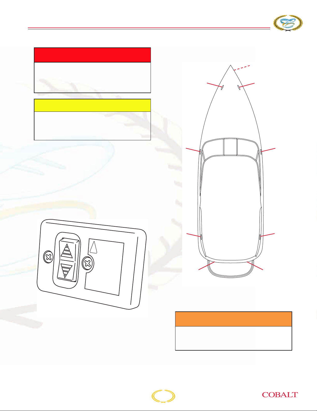
O
PERATING
A DANGER
To avoid injury or death, do not use the
arch for water sports, towing or as a
support. It is not designed to hold the
additional weight.
CAUTION
The arch with bimini is designed for
Cobalt factory-installed equipment only.
Do not add any additional equipment
without authorization from Cobalt.
I
NFORMATION
TIE-DOWN LOCATIONS
1
2
2
TRANSOM TILT SWITCH OPTIONAL
The remote transom tilt switch allows you to raise
or lower the drive unit from the stern. The remote tilt
switch is connected directly to the battery switch
and does not require the ignition key to be on. If
your boat has twin engines, each drive unit will
have a switch.
!
WARNING
Keep hands
and feet
away from
drive unit
when tilting
2
2
1– Bow Eye
2– Cleats
3 – Stern Eyes
2
2
33
COB_0001_A
276 Owner’s Manual
COB_0151
A WARNING
Avoid injury, death or property damage.
Never anchor a boat from the stern, and
keep the boat headed into the waves.
3-35

COBALT
276
BOWRIDER
S
ECTION
3
NOTICE: Only use properly
positioned slings to lift your
boat. Do not use deck cleats to
anchor or for towing. If towing,
only use the bow eye or the
stern eyes in a bridle manner.
Tie-down locations are for keeping your Cobalt boat
secured when moored. The bow eye and/or stern
eyes can also be used. Refer to Section 3,
Anchoring.
MOTOR BOX ASSEMBLY
A DANGER
To avoid injury or death, do not occupy
or operate the engine(s) when the motor
box is open. The motor box assembly is
a machinery guard.
The electric motor box assembly is controlled by its
switch at the helm. In the event of battery failure or
storage, the motor box can be opened manually.
TOOL KIT - OPTIONAL
A tool kit assists you with correcting minor
mechanical and electrical problems. For location of
the tool kit, refer to Section 1, Layout.
CAUTION
Avoid injury or damage to your boat. The
motor cover is heavy and may require
more than one person to lift it manually.
If lifting the box manually, position one
person at each grab handle and lift
straight up. Place support into position.
Do not operate the motor box assembly with any
obstructions that will interfere with its operation.
Damage to the motor box, hinges and lifting unit
can result. Before opening the motor box, make
sure no items are on top of the motor box and any
cushions, inserts or stored equipment are secure or
removed. Use the motor box support to support the
box once it is open. Be sure to return the support
back to its stow position and any obstructions are
cleared before closing the box. Wind and conditions
may allow the motor box to open beyond its limits.
Use caution during these conditions.
3-36
276 Owner’s Manual
276 Owner’s Manual
S
YSTEMS
INTRODUCTION
This section discusses the mechanical, electronic,
and manual operating systems of your Cobalt boat.
It describes basic operating characteristics and
provides information for efficient use of the
equipment, and for prevention of casualties. Be
sure to read and understand all information
provided before operating its systems.
S
ECTION
4
A WARNING
Avoid injury, death or damage to
equipment. Regularly inspect and
maintain all systems to prevent
unexpected hazards associated with
worn or faulty components. Be sure to
replace system components and
hardware with marine grade parts, not
automotive components.
276 Owner’s Manual
4-1

COBALT
STEREO AMP POWER
& REMOTE
SPEAKER
AMP POWER
XM ANTENNA
MACERATOR
HEAD BREAKER
PANEL
HEAD LIGHT
SPEAKER
INT, LIGHT
ANCHOR LT.
HOURMETER
BILGE PUMP
AFT GROUND
BILGE BLOWER
CAPT. CALL
RUDDER IND.
TRIM PUMP
FUEL SENDER
FUEL FILL
STORAGE LT.
NAV./LT
DOCK/LT
DOCK/LT
HORN
DASH STEREO REMOTE
SPEAKER
SPEAKER
SPEAKER
GROUND
HELM FEED
DASH CON.
SPEAKER
STORAGE LT.
REMOTE WIRE 30' CABLE
M/BOX ACTUATOR
VOLVO NEUTRA-SALT
XM ANTENNA
STEREO REMOTE LT.
STEREO REMOTE FROM STEREO
FEMALE END
WATER PUMP
SWIM/PLATE FORM LT
SWIM/PLATE FORM LT
SWIM/PLATE FORM LT
STORAGE LT.
STEREO & G/BOX LT.
STEREO REMOTE MALE END
TO STEREO & Y ADAPTER
TOWER SPEAKERS
SWITCH
ACC. PLUG
WATER PUMP
SWITCH
CAPT. CALL POWER
TRIM PUMP GROUND
M/BOX ACTUATOR
TRIM TAB
SUB WOOFER
SUB WOOFER
INT. LT
WINDLASS SW
WINDLASS
RELAY
HEATER SWITCH
TRIM TABS
BILGE PUMP POWER
INT.LT
TRAN. SPKER SW
STORAGE LT
FIRE EXT.
HEAD BLOWER
ELEC. HEAD SWITCH
ELEC. HEAD POWER
STORAGE LT
INT, LIGHT
TRIM TAB
TRIM PUMP
SPEAKER
AMP POWER
TRIM PUMP PWR
BILGE PUMP PWR
HELM POWER
CAPT. CALL PWR
STORAGE LT.
ANCHOR LT
HEATER BOX
WINDLASS BREAKER
276
BOWRIDER
ELECTRICAL WIRING HARNESS
SPEAKER
INT. LT
MACERATOR
HEAD BLOWER
HEAD LIGHT
ELEC. HEAD POWER
HEAD BREAKER
ELEC. HEAD SWITCH
PANEL
6543 12
STORAGE LT.
SWITCH
ACC. PLUG
STEREO & G/BOX LT.
STEREO REMOTE MALE END
TO STEREO & Y ADAPTER
TOWER SPEAKERS
REMOTE WIRE 30' CABLE
21
XM ANTENNA
NAV./LT
DOCK/LT
WINDLASS SW
GROUND
SPEAKER
XM ANTENNA
SUB WOOFER
HORN
RELAY
WINDLASS
DOCK/LT
SPEAKER
STORAGE LT.
DASH CON.
DASH STEREO REMOTE
HELM FEED
M/BOX ACTUATOR
TRIM TABS
HEATER SWITCH
S
ECTION
4
SPEAKER
INT, LIGHT
INT, LIGHT
ANCHOR LT
HEATER BOX
SPEAKER
TRIM PUMP
TRIM PUMP
STORAGE LT.
WINDLASS BREAKER
STORAGE LT
ANCHOR LT.
SWIM/PLATE FORM LT
SWIM/PLATE FORM LT
TRIM TAB
AMP POWER
TRIM PUMP PWR
BILGE PUMP PWR
STEREO AMP POWER
& REMOTE
HELM POWER
CAPT. CALL PWR
AFT GROUND
CAPT. CALL
RUDDER IND.
BILGE PUMP
BILGE BLOWER
VOLVO NEUTRA-SALT
CAPT. CALL POWER
SPEAKER
AMP POWER
SWITCH
WATER PUMP
FIRE EXT.
FUEL SENDER
STORAGE LT
HOURMETER
SWIM/PLATE FORM LT
M/BOX ACTUATOR
TRIM TAB
TRIM PUMP GROUND
STEREO REMOTE LT.
STEREO REMOTE FROM STEREO
43 21
COB_0285_A
INT.LT
BILGE PUMP POWER
SUB WOOFER
FUEL FILL
SPEAKER
FEMALE END
WATER PUMP
TRAN. SPKER SW
STORAGE LT.
4-2
276 Owner’s Manual

FUEL ROUTING
S
YSTEMS
276 Owner’s Manual
COB_0280_A
4-3

COBALT
276
WATER/PLUMBING
Fresh Water
BOWRIDER
S
ECTION
4
FRESH WATER IN
FRESHWATER
TANK (10-GAL)
FLOW
WATER TANK VENT/
CHECK VALVE
PUMP
TRANSOM
SHOWER
COB_0284_A
FILTER
4-4
276 Owner’s Manual

Electric Head Plumbing
ON DECK
(OPTIONAL)
WASTE PUMPOUT
S
YSTEMS
WASTE LINE ROUTING
WATER FILL ROUTING
HEAD SINK
SEA WATER ROUTING
WATER LINE ROUTING
ELECTRIC HEAD
WASTE TANK
FUEL TANK
MACERATOR
(OPTIONAL)
OVERBOARD
Y-VALVE
(OPTIONAL)
OPTIONAL COCKPIT SINK
DISCHARGE
(OPTIONAL)
276 Owner’s Manual
WATER FILL
ON DECK
4-5
ENGINE
WATER
WATER PUMP
TANK
TO OPTIONAL TRANSOM SHOWER
COB_0281_A

COBALT
276
BOWRIDER
S
ECTION
4
Water System
If your Cobalt boat is equipped with a transom
shower, standard or optional galley, the system
allows for fresh water to be onboard. A 12-volt DC
water pump operates the system. It is necessary for
the boat’s battery(ies) to be turned on for the water
system to operate. Consult your authorized Cobalt
dealer for winterization requirements.
To clean the water tank, add 1/4 cup of baking soda
per 10 gallons of fresh water into the tank and allow
it to stand in the tank for one day; then flush the
tank twice. If this is not sufficient to clean the tank,
replace the baking soda with 2 tablespoons of
bleach per 10 gallons of fresh water and repeat the
procedure. Refer to Section 1, Specifications, for
your boat’s freshwater capacity.
FIRE SUPPRESSION
EQUIPMENT
If your Cobalt boat is equipped with a fixed
automatic fire extinguisher that uses FE-241 (or
optional FM-200, for European requirements) as an
extinguishing agent, it is mounted on the engine
compartment and generator compartment (if
equipped). These extinguishers are activated when
the heat-sensitive head reaches a predetermined
temperature. The extinguisher discharges and
saturates the engine and/or generator
compartment, smothering the fire.
ELECTRICAL SYSTEM
Your Cobalt boat has a 12-volt negative ground DC
system. The positive wire is hot, and feeds current
from the batteries to all 12-volt equipment; the
negative wire is the ground.
The DC components are controlled from the helm
switches after the battery switch. If your Cobalt boat
has a cabin, it may have an electrical system panel
that supplies 12 volts to these types of accessories:
• Cabin lights
• Cockpit lights
•Head
• Freshwater pressure pump
• Air compressor
• Entertainment system
CIRCUIT BREAKER PANEL
Most electrical standard equipment devices are
controlled with circuit breakers located below the
helm. The breakers are labeled to identify the
device protected. These breakers will activate if
overloaded and cut power to the switch. To restore
power, turn off the device, push the breaker button
in and release. If the button continues to pop out
when the device is used, see your authorized
Cobalt dealer. Your boat may not be equipped with
all of these features or options.
Inspect fire extinguishers for proper charge before
operating the boat.
A WARNING
Avoid injury, death or explosion. DO
NOT open the engine compartment
hatch immediately. This will allow
oxygen to the fire, and flashback can
occur. When the fire extinguisher
discharge occurs, turn off all engines,
bilge blowers and electrical system
components.
4-6
IGNITION BILGE BLOWER
HORN NAVIGATION LIGHTS
INTERIOR LIGHTS BILGE PUMP
DOCKING
LIGHTS
AIR/WATER
PUMP
ACCESSORY ACCESSORY
STEREO
TRIM TAB
COB_0128A_A
276 Owner’s Manual

S
YSTEMS
FUSES
Some accessories or electrical components have
in-line fuses in them. Check the failed component
for the possibility of an in-line fuse if a tripped circuit
breaker is not found. Some of these accessories or
electrical components may not be included or
available on your boat.
In-line Fuse Components: Amperage
Depth Sounder 1 amp (located behind dash)
Air/Water Temperature Gauge 1 amp (located behind dash)
Trim Tab Control 20 amp (located behind dash or breaker used on dash)
Stereo 10 or 20 amp (breaker used on dash)
Bilge Pump 30 amp (located at battery switch)
Amplifier 30 amp (located at battery switch)
Bilge Pump #2510 15 amp (located behind dash)
Bilge Pump #1000 15 amp (located behind dash)
Sump Pump* 5 amp
Tank Level Monitor System* 4 amp
CO Monitor* 1 amp
Head Blower* 3" 5 amp
Head Blower* 4" 8 amp
*Fuses are located behind the cabin electric panel.
276 Owner’s Manual
4-7

COBALT
276
BOWRIDER
S
ECTION
LIGHTING/BULB REPLACEMENT
Some of these lights or electrical components may not be included or available on your boat.
Electrical Component Bulb Number
External Lights
Bow Light(s) 71
Anchor Light 1004
Arch 212-2
Internal Lights
Open Bulb Utility Light 1004 or 211
Cuddy Cabin Reading Light MR16
Black Rectangular Courtesy Light 1044-99A
Chrome Courtesy Light (Round) 90
Overhead Console Light GE 912
Dome Light 211
4
Ice Chest 194
Instrument Lighting
Tachometer 194 SF2
Speedometer 194 SD2
Voltmeter 658 S11
Oil Pressure 658 SH2
Temperature 658 SC2
Fuel 658 SC2
Trim 658 SC2
4-8
276 Owner’s Manual

S
YSTEMS
BATTERY CONNECTIONS
A WARNING
Avoid the potential of explosion from
shorting or arching. Keep the battery
connections tight and clean, the
terminal covers in place and the
battery(ies) secure in the restraint
system.
Loose battery connections can cause errant signals
to the boat’s electrical system.
Read and understand the safety information on or
supplied with your battery(ies). Maintain the
battery(ies) following the manufacturer’s
recommendations.
JUMP START STUDS
This receptacle allows for jump-starting an engine.
The receptacles have protective covers and must
stay in place when receptacles are not being used.
The covers identify the + positive (red) and the negative (black). The studs can be used to raise the
engine compartment when the batteries are low or
removed.
The jump start studs are located near or on the
battery switch panel.
NOTICE: Do not start an engine
from the jump start studs
without the batteries connected
to the boat’s charging system.
Damage to engine and charging
system will result.
OFF
W
IN
D
LASS
AM
P
LIFIER
A
M
P
LIFIER
BILGE PUMP
H
E
L
M
O
1
2
COB_0090_A
1 – Receptacle
1+2
1
COB_0282_A
276 Owner’s Manual
4-9

NOTES
COBALT
276
BOWRIDER
S
ECTION
4
4-10
276 Owner’s Manual
 Loading...