

Page 1

9400 Series
SDI/Fiber Multi-Channel Transports
with I/O Crosspoints
Product Manual
Cobalt Digital Inc.
2406 E. University Ave.
Urbana, IL 61802
Voice 217.344.1243 • Fax 217.344.1245
www.cobaltdigital.com
9400S-OM (V1.1)
Page 2

Copyright
©Copyright 2013, Cobalt Digital Inc. All Rights Reserved.
Duplication or distribution of this manual and any information contained within is strictly prohibited without the express written
permission of Coba lt Digital Inc. This manual and a ny information contained within, may not be re produced, distribute d, or
transmitted in any form, or by any means, for any purpose, without the express written permission of Cobalt Digital Inc.
Reproduction or reverse engineering of software used in this device is prohibited.
Disclaimer
The information in this document has been carefully examined and is believed to be entirely reliable. However, no responsibility
is assumed for inaccuracies. Furthermore, C obalt Digit al Inc. res erves the right to ma ke changes to any pro ducts herein to improve
readability, function, or design. Cobalt Digital Inc. does not assume any liability arising out of the application or use of any
product or circuit described herein.
Trademark Information
Cobalt® is a registered trademark of Cobalt Digital Inc.
FUSION3G
openGear
®
and COMPASS® are registered trademarks of Cobalt Digital Inc.
®
is a registered trademark of Ross Video Limited. DashBoard™ is a trademark of Ross Video Limited.
Congratulations on choosing the Cobalt
Crosspoints. The 9400 -S eries is part of a full l ine of mo dul ar p roce ssi ng a nd conv ersi on ge ar f or b roadc as t TV
environments. The Cobalt Digital Inc. line includes video decoders and encoders, audio embedders and deembedders, distribution amplifiers, format converters, remote control systems and much more. Should you
have questions pertaining to the installation or op eration of your 9 400-series card, please contact u s at the
contact information on the front cover.
®
9400-Series SDI/Fiber Multi-Channel Transports with I/O
Manual No.: 9400S-OM
Document Version: V1.1
Release Date: April 9, 2013
Description of
product/manual
changes:
- Update operating instructions for usage of alarm
disable settings.
- Corrections to minor errata.
9400S-OM (V1.1)
Page 3

Table of Contents
Chapter 1 Introduction . . . . . . . . . . . . . . . . . . . . . . . . . . . . . . . . . . . . . . . . . . . 1-1
Overview ................................................................................................................ 1-1
9400-Series Card Firmware Versions and this Manual.......................................... 1-2
Cobalt Reference Guides........................................................................................ 1-3
Manual Conventions............................................................................................... 1-3
Warnings, Cautions, and Notes .................................................................. 1-4
Labeling Symbol Definitions...................................................................... 1-4
Safety Summary ..................................................................................................... 1-5
Warnings..................................................................................................... 1-5
Cautions...................................................................................................... 1-5
9400-series Functional Description........................................................................ 1-6
Non-SMPTE Signal Handling.................................................................... 1-6
Tx Card Description ................................................................................... 1-6
Rx Card Description................................................................................... 1-7
User Control Interface ................................................................................ 1-8
9400-series Rear I/O Modules.................................................................... 1-9
Technical Specifications....................................................................................... 1-10
Warranty and Service Information ....................................................................... 1-12
Cobalt Digital Inc. Limited Warranty....................................................... 1-12
Contact Cobalt Digital Inc.................................................................................... 1-13
Chapter 2 Installation and Setup . . . . . . . . . . . . . . . . . . . . . . . . . . . . . . . . . . . 2-1
Overview ................................................................................................................ 2-1
Setting Card Switches............................................................................................. 2-1
Installing a Rear I/O Module.................................................................................. 2-3
9400-Series Rear I/O Modules ................................................................... 2-3
Rear I/O Module Installation...................................................................... 2-4
Installing the 9400-Series Card Into a Frame Slot ................................................. 2-5
Setting Up 9400-Series Network Remote Control................................................. 2-7
9400S-OM (V1.1) 9400 -SER I ES PRODU C T MANUAL i
Page 4

Chapter 3 Operating Instructions. . . . . . . . . . . . . . . . . . . . . . . . . . . . . . . . . . . 3-1
Overview................................................................................................................. 3-1
Accessing the 9400-Series Card Using DashBoard™ Remote Control................. 3-1
Checking Card Status.............................................................................................. 3-2
9400-Series Function Submenu List and Descriptions........................................... 3-4
9401 thru 9404 (Tx) Card Function Submenu List..................................... 3-4
Control/Status Tab (9401-9404 Tx)............................................................ 3-4
Fiber Optic Modules Info/Status Tab (9401-9404 Tx) .............................. 3-7
9411 thru 9414 (Rx) Card Function Submenu List .................................... 3-8
Control/Status Tab (9411-9414 Rx) .......................................................... 3-8
Card-Edge Control................................................................................................ 3-10
Fiber Optic Modules Info/Status Tab (9411-9414 Rx) ............................ 3-10
Troubleshooting.................................................................................................... 3-11
Basic Troubleshooting Checks ................................................................. 3-11
9400 Signal Processing Error Troubleshooting........................................ 3-11
Troubleshooting Network/Remote Control Errors ................................... 3-12
In Case of Problems.................................................................................. 3-12
9400S-OM (V1.1) 9400 -SER I ES PR ODUCT MANUAL ii
Page 5

Overview
Chapter 1
Chapter 1 Introduction
This manual provides installati on and o per at ing instr uct ions for the
9400-series SDI/Fiber Multi-Channel Transports with I/O Crosspoint cards
(also referred to herein as the 9400-series).
The 9400-series consist of the following BNC-to-Fiber (Tx) and
Fiber-to-BNC (Rx) transport cards:
BNC-to-Fiber (Tx) Fiber-to-BNC (Rx)
9401
9402
9403
9404
4 BNC In x 1 Fiber Out;
4x1 Crosspoint
4 BNC In x 2 Fiber Out;
4x2 Crosspoint
4 BNC In x 3 Fiber Out;
4x3 Crosspoint
4 BNC In x 4 Fiber Out;
4x4 Crosspoint
9411
9412
9413
9414
1 Fiber In x 4 BNC Out;
1x4 Crosspoint
2 Fiber In x 4 BNC Out;
2x4 Crosspoint
3 Fiber In x 4 BNC Out;
3x4 Crosspoint
4 Fiber In x 4 BNC Out;
4x4 Crosspoint
Note: This manual covers the 9400-series, which consists of the cards listed above.
These cards vary only in Tx or Rx designation and channel capacity; the differences are described in detail later in this section.
Where applicable, descriptions related exclusively to a particular card are
denoted, for example as (9401 only). In all other aspects, all cards in this
series function identically as described in this manual.
9400S-OM (V1.1) 9400-SERIES PRODUCT MANUAL 1-1
Page 6

1 9400-Series Card Firmware Versions and this Manual
This manual consists of the following chapters:
• Chapter 1, “Introduction” – Provides information about this
manual and what is covered. Also provides general information
regarding the 9400-series.
• Chapter 2, “Installation and Setup” – Provides instructions for
installing the 9400-series in a frame, and optionally installing a
9400-series Rear
I/O Module.
• Chapter 3, “Operating Instructions” – Provides overviews of
operating controls and instructions for using the 9400-series.
This chapter contains the following information:
• Manual Conventions (p. 1-3)
• Safety Summary (p. 1-5)
• 9400-series Functional Description (p. 1-6)
• Technical Specifications (p. 1-10)
• Warranty and Service Information (p. 1-12)
• Contact Cobalt Digital Inc. (p. 1-13)
9400-Series Card Firmware Versions and this Manual
When applicable, Cobalt Digital Inc. provides for continual product
enhancements through software updates. As such, functions described in this
manual may pertain specifically to cards loaded with a particular software
build.
The Software Version of your card can be checked by viewing the Ca r d I n fo
menu in DashBoard™. You can then check our websi te fo r the late st softwa re
version currently released for the card as described below.
1-2 9400-SERIES PRODUCT MANUAL 9400S-OM (V1.1)
Page 7

Introduction Cobalt Reference Guides
Check our website and proceed as follows if your card’s software does not
match the latest version:
Card Software earlier than
latest version
Card Software newer than
version in manual
Card is not loaded with the latest software. Not all
functions and/or specified performance described in
this manual may be available.
You can update your card with the new Update
software by going to the Support>Firmware link at
www.cobaltdigital.com. Download “Firmware
Update Guide”, which provides simple instructions
for downloading the latest firmware for your card
onto your computer, and then uploading it to your
card through DashBoard™.
Software updates are fi eld-inst alled wit hout any
need to remove the card from its frame.
A new manual is expediently released whenever a
card’s software is updated and specifications
and/or functionality have changed as compared
to an earlier version (a new manual is not
necessarily released if specifications and/or
functionality have not changed). A manual earlier
than a card’s software version may not completely
or accurately describe all functions available for
your card.
If your card shows features not described in this
manual, you can check for the latest manual (if
applicable) and download it by going to the
Support>Documents>Product Information and
Manuals link at www.cobaltdigital.com.
Cobalt Reference Guides
From the Cobalt® web home page, go to Support>Documents>Reference
Guides
updates, application notes and other topics.
Manual Conventions
In this manual, the terms below are applicable as follows:
for easy to use guide s coverin g networ k remote cont rol, c ard firmwar e
• 9400-series refers to the 9400-series SDI/Fiber Multi-Channel
Transports with I/O Crosspoint cards.
• Frame refers to the 8321 (or similar) frame that houses the Cobalt
COMPASS™ cards.
• Device and/or Card refers to a COMPASS™ card.
• System and/or Video System refers to the mix of interconnected
production and terminal equipment in which the 9400-series and
other COMPASS™ cards operate.
®
9400S-OM (V1.1) 9400-SERIES PRODUCT MANUAL 1-3
Page 8
1 Manual Conventions
Warnings, Cautions, and Notes
Certain items in this manual are highlighted by special messages. The
definitions are provided below.
Warnings
Warning messages indicate a possible hazard which, if not avoided, could
result in personal injury or death.
Cautions
Caution messages indicate a problem or incorrect practice which, if not
avoided, could result in improper operation or damage to the product.
Notes
Notes pro vide suppl emental information to the accompanying text. Notes
typically precede the text to which they apply.
Labeling Symbol Definitions
Attention, consult accompanying documents.
Electronic device or assembly is susceptible to damage from an ESD
event. Han dle only using appropriate ESD prevention practices.
If ESD wrist strap is not available, handle card only by edges and avoid
contact with any connectors or components.
CLASS 1 LASER PRODUCT
IEC 60825-1:2007
Caution - INVISIBLE LASER RADIATION WHEN OPEN. AVOID
EXPOSURE TO THE BEAM.
Symbol (WEEE 2002/96/EC)
For product disposal, ensure the following:
• Do not dispose of this product as unsorted municipal waste.
• Collect this product separately.
• Use collection and return systems available to you.
1-4 9400-SERIES PRODUCT MANUAL 9400S-OM (V1.1)
Page 9

Introduction Safety Summary
Safety Summary
Warnings
! WARNING !
! WARNING !
Cautions
CAUTION
CAUTION
CAUTION
CAUTION
T o re duce risk of electr ic shock do not remove line voltage service barrier cover on frame
equipment containing an AC power supply. NO USER SERVICEABLE PARTS INSIDE.
REFER SERVICING TO QUALIFIED SERVICE PERSONNEL.
• Do not stare at, or into, broken, or damaged, fibers.
• Do not stare at, or into, optical connectors.
• Only properly trained and authorized personnel should be permitted to perform laser/
fiber optic operations.
• Ensure that appropriate labels are displayed in plain view and in close proximity to the
optical port on the protective housing/access panel of the terminal equipment.
This device is intended for environmentally controlled use only in appropriate video
terminal equipment operating environments.
This product is intended to be a component product of an openGear® frame. Refer to the
openGear® frame Owner's Manual for important safety instructions regarding the proper
installation and safe operation of the frame as well as its component products.
Heat and power distribution requirements within a frame may dictate specific slot
placement of cards. Cards with many heat-producing components should be arranged to
avoid areas of excess heat build-up, particularly in frames using only convection cooling.
If required, make certain Rear I/O Module(s) is installed before installing the card into the
frame slot. Damage to card and/or Rear I/O Module can occur if module installation is
attempted with card already installed in slot.
CAUTION
9400S-OM (V1.1) 9400-SERIES PRODUCT MANUAL 1-5
If card resists fully engaging in rear I/O mod ule mating connec tor, check for alignment and
proper insertion in slot tracks. Damage to card and/or rear I/O module may occur if
improper card insertion is attempted.
Page 10

1 9400-series Functional Description
9400-series Functional Description
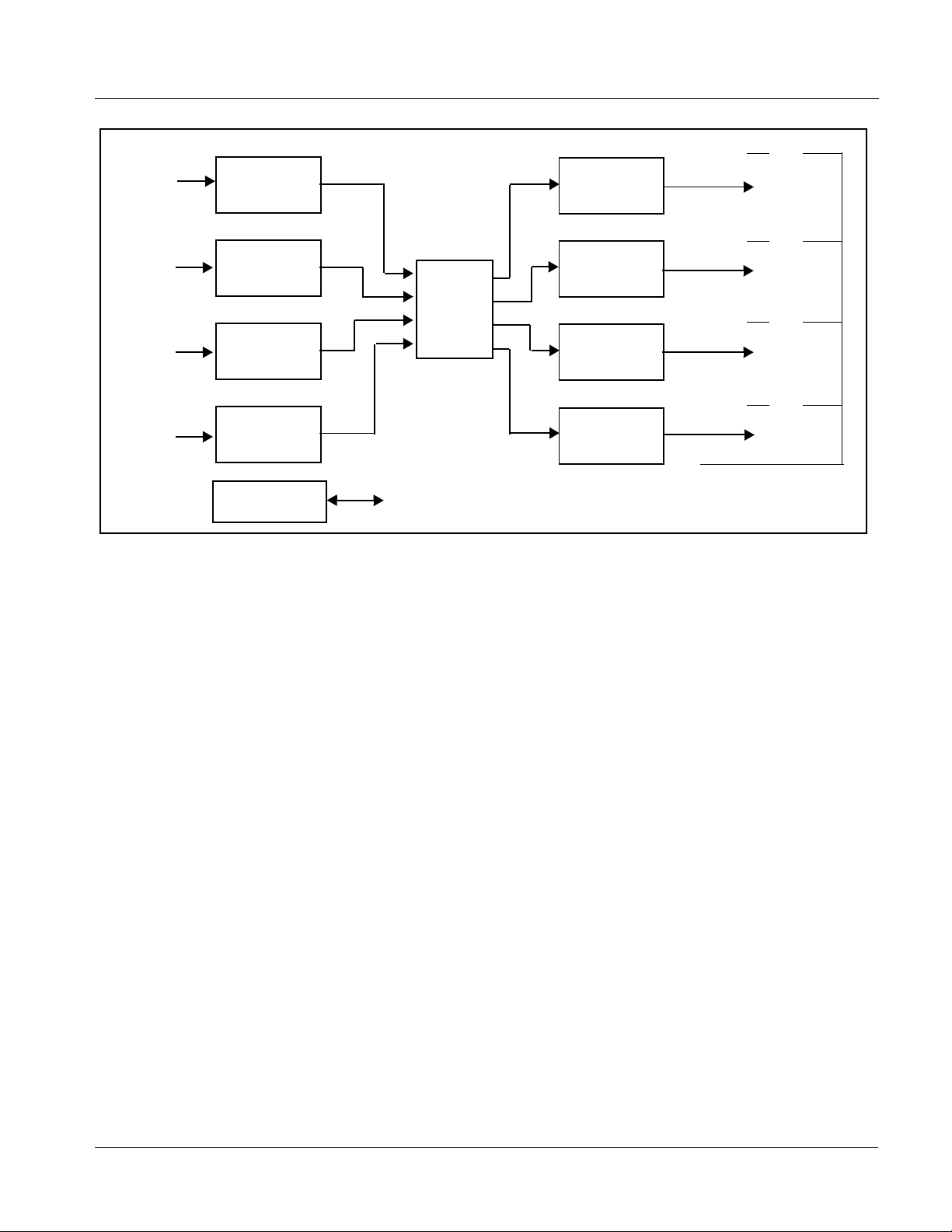
Figure 1-1 shows a fu nctional block di agram of t he 9400-s eries tra nsmit car ds
9401 thru 9404 which ar e 4x1 t hru 4x4 75Ω BNC-to -fibe r tra nsport s with I/O
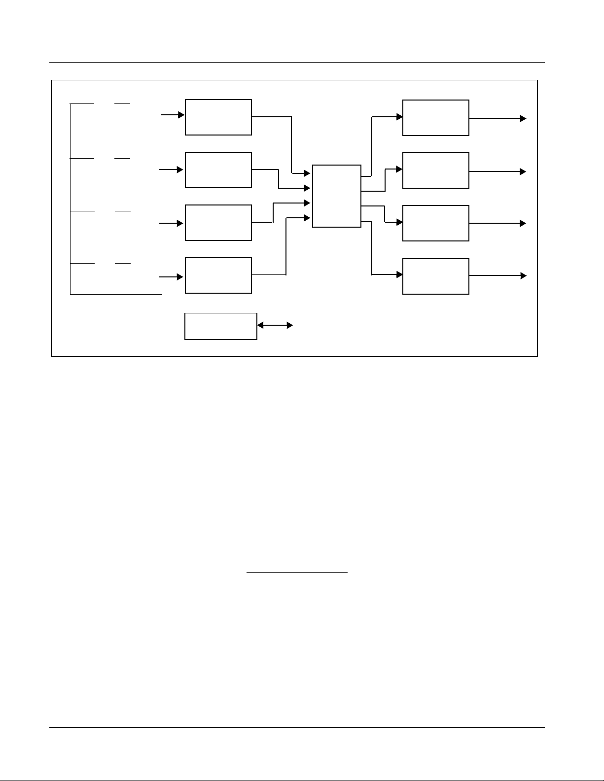
crosspoints. Figure 1-2 shows a functional block diagram of the 9400-series
transmit cards 9411 thru 9414 which are 1x4 thru 4x4 fiber-to-75Ω BNC
transports with I/O crosspoints.
Transmitter (Tx) and receiver (Rx) card groups are individually described
below. Except for channel capacity, all respective Tx cards and Rx cards
function i dentically.
Non-SMPTE Signal Handling
All 9400 cards (whether Tx or Rx) are equipped with EQ/reclocking and
automute tailored for SMPTE signals. Typically, automute is invoked for
signals outside of a range from 19 Mbps to 3 Gbps. These functions help
reject noise in the transport and help recover received si gnals that may be
degraded due to long cable runs. EQ/reclocking is applied before the
automute function, allowing the automute to blank signal transfer when a
signal is not reliably locked by reclocking. When handling non-SMPTE
signals (specifically signals slower than 19 Mbps), the card’s reclocking and
automute functions can be set to bypass so that non-SMPTE signals are not
rejected by these functions.
Tx Card Description
Four 75Ω BNC ports are routed to individual EQ/reclocking which provide
on-off selecta ble EQ/rec lock/aut omute. Via card hardware switches or remote
control, EQ/reclocking and automute can be disabled (on an individual
channel-by-channel basis) to allow signals lower than 19 Mbps from being
rejected as noise. The reclocker and automute can manually be set to bypass
operation to reliably pass non-SMPTE signals (see Non-SMPTE Signal
Handling above).
The crosspoint allows the four BNC inputs to be routed to up to four fiber
outputs (via individ ual fibe r opti c module s) per card a s s pecif ied in Overvie w
(p. 1-1). The crosspoint can als o allow mult iple out puts to serve as a DA with
the same input BNC source being applied to multiple fiber outputs.
Electrical-to-fi ber conversi on is via discr ete Tx fiber opti c modules whic h can
be fitted with various connector types as ordered.
1-6 9400-SERIES PRODUCT MANUAL 9400S-OM (V1.1)
Page 11
Introduction 9400-series Functional Description
9404
BNC IN 1
On/Off
Selectable
EQ/Reclock
Elect/Optical
Converter
FIBER OUT 4
BNC IN 2
BNC IN 3
BNC IN 4
On/Off
Selectable
EQ/Reclock
On/Off
Selectable
EQ/Reclock
On/Off
Selectable
EQ/Reclock
Network Remote
Control
Rx Card Description
Elect/Optical
Converter
Crosspoint
Elect/Optical
Converter
Elect/Optical
Converter
Ethernet 10/100 (on frame)
Figure 1-1 9401 thru 9404 Tx Card Functional Block Diagram
Up to four fiber inputs are received using discrete Rx fiber optic module
subassemblies which can be fitted with various connector types as ordered.
The received inputs are routed to the crosspoint.
9403
FIBER OUT 3
9402
FIBER OUT 2
9401
FIBER OUT 1
The crosspoint allows the up to four fiber inputs to be routed to four 75Ω
BNC output ports fiber outputs per card module as specified in Overview (p.
1-1). The crosspoint can allow multiple outputs to serve as a DA with the
same input fiber source being applied to multiple BNC outputs.
Vi a card hardware switches or remote control, reclocking and automute can
be disabled (on an individual channel-by-channel basis) to allow signals
lower than 19 Mbps from being re jected as noise. The recloc ker can manual ly
be set to bypass operation to reliably pass non-SMPTE signals (see
Non-SMPTE Signal Handling above).
9400S-OM (V1.1) 9400-SERIES PRODUCT MANUAL 1-7
Page 12
1 9400-series Functional Description
9411
9412
9413
9414
FIBER IN 1
FIBER IN 2
FIBER IN 3
FIBER IN 4
Optical/Elect
Converter
Optical/Elect
Converter
Optical/Elect
Converter
Optical/Elect
Converter
Network Remote
Control
Crosspoint
Ethernet 10/100 (on frame)
Selectable
Selectable
Selectable
Selectable
Figure 1-2 9411 thru 9414 Rx Card Functional Block Diagram
On/Off
Reclock
On/Off
Reclock
On/Off
/Reclock
On/Off
Reclock
BNC OUT 4
BNC OUT 3
BNC OUT 2
BNC OUT 1
User Control Interface
The 9400-series uses DashBoard™ as the norm al graphical user interface for
the card, similar to other Cobalt
Using DashBoard™, the 9400-series and other cards installed in openGear
frames such as the Cobalt
and monitor
1
. DashBoard™ allows users to vie w all frames on a net work with
®
COMPASS™ cards.
®
8321-C Frame can be controlled fr om a compute r
®
control and monitoring for all populated slots inside a frame. This simplifies
the setup and use of numerous modules in a large installation and offers the
ability to centralize monitoring. Cards define their controllable parameters to
DashBoard™, so the control interface is always up to date.
The DashBoard™ software can be downloaded from the Cobalt Digital Inc.
website: www.cobaltdigital.com
(enter “DashBoard” in the search window).
The DashBoard™ user interface is described in Chapter 3,“Operating
Instructions”.
1. openGear® is a registered trademark of Ross Video Limited. DashBoard™ is a trademark of Ross
Video Limited.
1-8 9400-SERIES PRODUCT MANUAL 9400S-OM (V1.1)
Page 13

Introduction 9400-series Functional Description
Note: If network remote control is to be used for the frame and the frame has not yet
9400-series Rear I/O Modules
been set up for remote control, Cobalt
User Guide (PN 9000RCS-RM) provides thorough information and
step-by-step instructions for setting up network remote control of
COMPASS™ cards using DashBoard™. (Cobalt
OGCP-9000/CC Remote Control Panel product manuals have complete
instruct ions for setting up remote control using a Remote Control Panel.)
Download a copy of this guide by clicking on the Support>Documents>
Reference Guides link at www.cobaltdigital.com and then select DashBoard
Remote Control Setup Guide as a download, or contact Cobalt
Contact Cobalt Digital Inc. (p. 1-13).
®
reference guide Remote Control
®
OGCP-9000 and
®
as listed in
The 9400-series physically interfaces to system video connections at the rear
of its frame using a Rear I/O Module.
All inputs and outputs shown in the 9400-series Functional Block Diagram
(Figures 1-1 and 1-2) enter and exit the card via the card edge backplane
connector. The Rear I/O Module breaks out the 9400-series card edge
connections and exposes the fiber transceiver subassemblies to connectors
that interface with ot her compone nts and sys tems in the signal chain. Various
Rear I/O Modules are available for various fiber connection formats. See
“Installation”, Chapter 2 for Rear I/O Module connections.
9400S-OM (V1.1) 9400-SERIES PRODUCT MANUAL 1-9
Page 14

1 Technical Specifications
Technical Specifications
Table 1-1 lists the technical specifications for the 9400-series SDI/Fiber
Multi-Channel Transports with I/O Crosspoint cards.
Table 1-1 Technical Specifications
Item Characteristic
Part number, nomenclature BNC-to-Fiber Cards (Tx):
• 9401 (4 In / 1 Out BNC-to-Fiber Transmitter / Crosspoint Card)
• 9402 (4 In / 2 Out BNC-to-Fiber Transmitter / Crosspoint Card)
• 9403 (4 In / 3 Out BNC-to-Fiber Transmitter / Crosspoint Card)
• 9404 (4 In / 4 Out BNC-to-Fiber Transmitter / Crosspoint Card)
BNC-to-Fiber Cards (Tx):
• 9411 (1 In / 4 Out Fiber-to-BNC Receiver / Crosspoint Card)
• 9412 (2 In / 4 Out Fiber-to-BNC Receiver / Crosspoint Card)
• 9413 (3 In / 4 Out Fiber-to-BNC Receiver / Crosspoint Card)
• 9414 (4 In / 4 Out Fiber-to-BNC Receiver / Crosspoint Card)
Installation/usage environment Intended for installation and usage in frame meeting openGear
modular system definition.
®
Power consumption < 10 Watts maximum
Environmental:
Operating temperature:
Relative humidity (operating or storage):
Frame communication 10/100 Mbps Ethernet with Auto-MDIX.
Tx/Rx Fiber Range 40 km (24.8 mi) max
Fiber Connector: LC, ST, SC, or FC
Standards Supported: SMPTE 259M-C, SMPTE 292M, SMPTE 425M, SMPTE 297M,
32° – 104° F (0° – 40° C)
< 95%, non-condensing
Single-Mode optics; rates thru HD:
24 km (14.9 mi) max
Note: Connector type must be specified as part of card rear I/O
module part number. Connector types cannot be mixed on a single
rear I/O module. See Installation and Setup, Chapter 2 for more
information.
DVB/ASI, SMPTE 259M with EDH
1-10 9400-SERIES PRODUCT MANUAL 9400S-OM (V1.1)
Page 15

Introduction Technical Specifications
Table 1-1 Technical Specifications — continued
Item Characteristic
9401 thru 9404 (Tx Card) I/O
Specifications:
9401 thru 9404 (Rx Card) I/O
Specifications:
Input Type:
BNC, 75Ω
Input/Output Loop Return Loss:
>15 dB up to 1.5 GHz
>10 dB up to 3 GHz
Transmitter Wavelength:
1310 nm Single Mode
Optical Power:
-5 dBm to 0 dBm
Laser Power Range:
Laser Class 1
Added Jitter:
<0.03 UI under 1 MHz
Output Type:
Fiber LC, ST, SC, or FC
Input Type:
Fiber LC, ST, SC, or FC
Wavelength:
1100 to 1600nm
Optical Sensitivity
Pathological 3Gbps: -18 dBm
Pathological HD-SDI: -20 dBm
Output Type:
BNC, 75
Output Return Loss:
>15 dB up to 1.5 GHz
>10 dB up to 3 GHz
Added Jitter:
<0.03 UI under 1 MHz
Output Type:
BNC, 75Ω
9400S-OM (V1.1) 9400-SERIES PRODUCT MANUAL 1-11
Page 16

1 Warranty and Service Information
Warranty and Service Information
Cobalt Digital Inc. Limited Warranty
This product is warranted to be free from defects in material and workmanship for a period of five (5)
years from the date of shipment to the original purchaser, except that 4000, 5000, 6000, 8000 series
power supplies, and Dolby
material and workmanship for a period of one (1) year.
Cobalt Digital Inc. 's (“Cobalt”) sole obligation under this warranty shall be limited to, at its option, (i)
the repair or (ii) replacement of the product, and the determinati on of whether a defect is covered under
this limited warranty shall be made at the sole discretion of Cobalt.
This limited warranty applies onl y to the original end-purchaser of the pr oduct, and is not assigna ble or
transferrable therefrom. This warranty is limited to defects i n material a nd workman shi p, and shal l not
apply to acts of God, accidents, or negligence on behalf of the purchaser, and shall be voided upon the
misuse, abuse, alteration, or modification of the product. Only Cobalt authorized factory
representatives are authorized to make repairs to the product, and any unauthorized attempt to repair
this product shall immediately void the warranty. Please contact Cobalt Technical Support for more
information.
®
modules (where applicable) are warranted to be free from defects in
To facilitate the resolution of warranty related issues , Cobalt recommends registering the product by
completing and returning a product registration form. In the event of a warrantable defect, the
purchaser shall notify Cobalt with a description of the problem, and Cobalt shall provide the purchaser
with a Return Material Authorization (“RMA”). For return, defective product s should be double boxed,
and sufficiently protected, in the original packaging, or equivalent, and shipped to the Cobalt Factory
Service Center, postage prepaid and insured for the purchase price. The purchaser should include the
RMA number, description of the problem encountered, date purchased, name of dealer purchased
from, and serial number with the shipment.
Cobalt Digital Inc. Factory Service Center
2406 E. University Avenue Office: (217) 344-1243
Urbana, IL 61802 USA Fax: (217) 344-1245
www.cobaltdigital.com Email: info@cobaltdigital.com
THIS LIMITED WARRANTY IS EXPRESSLY IN LIEU OF ALL OTHER WARRANTIES
EXPRESSED OR IMPLIED, INCLUDING THE WARRANTIES OF MERCHANTABILITY AND
FITNESS FOR A PARTICULAR PURPOSE AND OF ALL OTHER OBLIGATIONS OR
LIABILITIES ON COBALT'S PART. ANY SOFTWARE PROVIDED WITH, OR FOR USE WITH,
THE PRODUCT IS PROVIDED “AS IS.” THE BUYER OF THE PRODUCT ACK NOWLEDGES
THAT NO OTHER RE PRESENTATIONS WERE MADE OR RELIED UPON WIT H RESPECT TO
THE QUALITY AND FUNCTION OF THE GOODS HEREIN SOLD. COBALT PRODUCTS ARE
NOT AUTHORIZED FOR USE IN LIFE SUP PORT APPLICATIONS.
COBALT'S LIABILITY, WHETHER IN CONTRACT, TORT, WARRANTY, OR OTHERWISE, IS
LIMITED TO THE REPAIR OR REPLACEMENT, AT ITS OPTION, OF ANY DEFECTIVE
PRODUCT, AND SHALL IN NO EVENT INCLUDE SPECIAL, INDIRECT, INCIDENTAL, OR
CONSEQUENTIAL DAMAGES (INCL UDING LOST PROFITS), EVEN IF IT HAS BEEN
ADVISED OF THE POSSIBILITY OF SUCH DAMAGES.
1-12 9400-SERIES PRODUCT MANUAL 9400S-OM (V1.1)
Page 17

Introduction Contact Cobalt Digital Inc.
Contact Cobalt Digital Inc.
Feel free to contact ou r th oro ugh and professional support representatives for
any of the following:
• Name and address of your local dealer
• Product information and pricing
• Technical support
• Upcoming trade show informat ion
Phone: (217) 344-1243
Fax: (217) 344-1245
Web: www.cobaltdigital.com
General Information: info@cobaltdigital.com
Technical Support: support@cobaltdigital.com
9400S-OM (V1.1) 9400-SERIES PRODUCT MANUAL 1-13
Page 18

This page intentionally blank
1-14 9400-SERIES PRODUCT MANUAL 9400S-OM (V1.1)
Page 19

Overview
Setting Card Switches
Note: • If using DashBoard™ or other network remote control, disregard this
Chapter 2
Chapter 2 Installation and Setup
This chapter contains the following information:
• Setting Card Switches (p. 2-1)
• Installing the 9400-Series Card Into a Frame Slot (p. 2-5)
• Installing a Rear I/O Module (p. 2-3)
• Setting Up 9400-Series Network Remote Control (p. 2-7)
section. Default switch positions allow remote control operation of all
functions.
• If card-edge controls described here are set to card-edge (instead of
DashBoard™), DashBoard™ or other network remote control will be locked
out. Default positions allow DashBoard™ remote control. Do not change
settings here unless card-edge control of these functions is desired.
(See Figure 2-1.) For each channel, card-edge swit ches allow setting channel
Auto Mute and Reclocker Bypass either on or off manually (instead of via
DashBoard™ remote control). The default switch positions allow remote
control.
If the card is intended to handle signals that are not recognized SMPTE
signals and rates, it is recommended that auto-mute and reclock be bypassed
to prevent the signals from inadvertently being rejected as noise.
These functions can be enabled or disabled using DashBoard™ or the
card-edge switches described here.
• If DashBoard™ remote control of au to-mute/ reclock ena ble/b ypass is
to be used, leave the switches in the default settings and skip to
Installing a Rear I/O Module (p. 2-3). Then use DashBoard™ to
configure the Auto Mute and Reclocker settings as described in
Chapter 3, Operating Instructions.
• If DashBoard™ remote control of au to-mute/ reclock ena ble/b ypass is
not to be used and manual local control is desired, set each of the
switches as described below before installing the card.
9400S-OM (V1.1) 9400-SERIES PRODUCT MANUAL 2-1
Page 20

2 Setting Card Switches
Figure 2-1 shows and describes the 9400-series card-edge controls that allow
card-edge control of Reclocker an d Auto Mute enable/disable.
-1
-2
SW1
-3
-4
FRONT OF CARD
SW2
SW3
-1
-2
-3
-4
-1
-2
-3
-4
As shown, switch levers are set to
OFF with lever up. Press lever
down to set to ON position.
Switch Setting
SW1-1 On = Automute control via card-edge switch SW2 (DashBoard™ Automute control locked out)
SW1-2 On = Reclocker control via card-edge switch SW3 (DashBoard™ Reclocker control locked out)
SW1-3
SW1-4
Note: Switch SW2 functional only if switch SW1-1 set to On (card-edge Automute control)
SW2-1 On = Automute Channel 1 disabled Off = Automute Channel 1 enabled
SW2-2 On = Automute Channel 2 disabled Off = Automute Channel 2 enabled
SW2-3 On = Automute Channel 3 disabled Off = Automute Channel 3 enabled
SW2-4 On = Automute Channel 4 disabled Off = Automute Channel 4 enabled
Note: Switch SW3 functional only if switch SW1-2 set to On (card-edge Reclocker control)
SW3-1 On = Reclocker bypass Channel 1 enabled Off = Reclocker bypass Channel 1 disabled
SW3-2 On = Reclocker bypass Channel 2 enabled Off = Reclocker bypass Channel 2 disabled
SW3-3 On = Reclocker bypass Channel 3 enabled Off = Reclocker bypass Channel 3 disabled
SW3-4 On = Reclocker bypass Channel 4 enabled Off = Reclocker bypass Channel 4 disabled
Off = Automute c on trol via DashBoard (card-edge Automute control locked out)
Off = Reclocker control via DashBoard (card-edge Reclocker control locked out)
Not used
Figure 2-1 9400-Series Card Edge Controls
2-2 9400-SERIES PRODUCT MANUAL 9400S-OM (V1.1)
Page 21

Installation and Setup Installing a Rear I/O Module
Installing a Rear I/O Module
9400-Series Rear I/O Modules
Table 2-1 shows and describes the full assortment of Rear I/O Modules
specifical ly for use with the 9400-Series.
Table 2-1 9400-Series Rear I/O Modules
9400-Series Rear I/O Module Description
CLASS 1 LASER PRODUCT - IEC 60825-1:2007. Never look into fiber connector or cable end
of device transmitting an optical signal. The transmitted light is not visible and can cause
permanent eye damage. Do not perform connection/disconnection with sending or receiving
device powered.
Note:Rear I/O Modules should be ordered corresponding to the card model and format of fiber connection desired. All 9400-series
rear modules are standard-width (occupies 2 card slots) and are available only for 20-slot frames (e.g., 8321 frame). See below.
RM20-9404-B 20-Slot Frame Rear I/O Module (Standard Width) 4 B NC In, 4 Fiber Out
RM20-9403-B 20-Slot Frame Rear I/O Module (Standard Width) 4 B NC In, 3 Fiber Out
RM20-9402-B 20-Slot Frame Rear I/O Module (Standard Width) 4 B NC In, 2 Fiber Out
RM20-9401-B 20-Slot Frame Rear I/O Module (Standard Width) 4 B NC In, 1 Fiber Out
RM20-9414-B 20-Slot Frame Rear I/O Module (Standard Width) 4 F iber In, 4 BNC Out
RM20-9413-B 20-Slot Frame Rear I/O Module (Standard Width) 3 F iber In, 4 BNC Out
RM20-9412-B 20-Slot Frame Rear I/O Module (Standard Width) 2 F iber In, 4 BNC Out
RM20-9411-B 20-Slot Frame Rear I/O Module (Standard Width) 1 Fiber In, 4 BNC Out
Note:Add fiber connector suffix to part numbers above to specify fiber connection type (-LC, -ST, -SC, -FC). (For example,
RM20-9404-B fitted with LC connectors is ordered as “RM20-9404-B-LC”.)
RM20-9401-B thru RM20-9404-B Provides the following connections for Tx cards 9401
thru 9404:
• Four BNC coaxial inputs (BNC IN 1 thru BNC IN 4)
• Up to four Fiber outputs (FIBER OUT 1 thru
FIBER OUT 4)
9400S-OM (V1.1) 9400-SERIES PRODUCT MANUAL 2-3
Page 22

2 Installing a Rear I/O Module
Table 2-1 9400-Series Rear I/O Modules — continued
9400-Series Rear I/O Module Description
RM20-9411-B thru RM20-9414-B Provides the following connections for Rx cards 9411
thru 9414:
• Up to four Fiber inputs (FIBER IN 1 thru
FIBER IN 4)
• Four BNC coaxial outputs (BNC OUT 1 thru
BNC OUT 4)
Rear I/O Module Installation
Install a Rear I/O Module as follows:
1. On the frame, determine the slot in which the 9400-series card is to be
installed.
2. In the mounting area corresponding to the slot location, install
Rear I/O Module as shown in Figure 2-2.
2-4 9400-SERIES PRODUCT MANUAL 9400S-OM (V1.1)
Page 23

Installation and Setup Installing the 9400-Series Card Into a Frame Slot
Align and engage mounting tab on Rear
I/O Module with the module seating slot
1
on rear of frame chassis.
DSCN3483A.JPG
Hold top of Rear I/O Module flush against
frame chassis and start the captive screw.
2
Lightly tighten captive screw.
DSCN3487A.JPG
Figure 2-2 Rear I/O Module Installation
Installing the 9400-Series Card Into a Frame Slot
CAUTION
Heat and power distribution requirements within a frame may dictate specific
slot placement of cards. Cards wi th many he at-producing com ponent s shoul d
be arranged to avoid areas of excess heat build-up, particularly in frames
using only convection cooling.
CAUTION
This device contains semiconductor devices which are
susceptible to serious damage from Electrostatic
Discharge (ESD). ESD damage may not be immediately
apparent and can affect the long-term reliability of the
device.
Avoid handling circuit boards in high static environments
such as carpeted areas, and when wearing synthetic fiber
clothing. Always use proper ESD handling precautions
and equipment when working on circuit boards and
related equipment.
9400S-OM (V1.1) 9400-SERIES PRODUCT MANUAL 2-5
Page 24

2 Installing the 9400-Series Card Into a Frame Slot
Note: A Rear I/O Module is required before cabling can be connected. Refer to
Installing a Rear I/O Module (p. 2-3) for rear I/O module installation procedure.
CAUTION
If required, make certain Rear I/O Module(s) is installed before installing the
card into the frame slot. Damage to card and/or Rear I/O Module can occur if
module installation is attempted with card already installed in slot.
Note: Check the packaging in which the card was shipped for any extra items such
as a Rear I/O Module connection label. In some cases, this label is shipped
with the card and to be installed on the Rear I/O connector bank corresponding to the slot location of the card.
Install the card into a fr ame slot as follows:
1. Determine the slot in which the card is to be installed.
2. Open the frame front access panel.
3. Remove an protective caps on card fiber optic module (s).
4. While holding the card by the card edges, align the card such that the
plastic ejector tab is on the bottom.
5. Align the card with the top and bottom guides of the slot in which the
card is being installed.
6. Gradually slide the card into the slot. When resistance is noticed, g ently
continue pushing the card until its rear printed circuit edge terminals
engage fully into the rear I/O module mating connector.
An audible “click” is heard when the card fiber optic module(s) mates
with the blindmate adapter on the rear module.
CAUTION
If card resists fully engaging in rear I/O module mating connector, check for
alignment and proper insertion in slot tracks. Damage to card and/or rear I/O
module may occur if improper card insertion is attempted.
7.
Verify that the card is fully engaged in rear I/O module mating
connector.
8. Close the frame front access panel.
9. Connect BNC cables in accordance with the rear I/O module installed.
10. Connect fiber connections in accordance with the rear I/O module
installed. Remove the dust cap from the fiber ports on the rear I/O
module and insert cable into transceiver module.
11. Repeat steps 1 through 10 for other 9400-series cards.
2-6 9400-SERIES PRODUCT MANUAL 9400S-OM (V1.1)
Page 25

Installation and Setup Setting Up 9400-Series Network Remote Control
Note: To remove a card, press down on the ejector tab to unseat the card from the
rear I/O module mating connector. Evenly draw the card from its slot.
12. If network remote control is to be used for the frame and the frame has
not yet been set up for remo te co ntr ol , perf or m se tup in acc ordance with
Setting Up 9400-Series Network Remote Control (p. 2-7).
Note: If installing a card in a frame already equipped for, and connected to
DashBoard™, no network setup is required for the card. The card will be discovered by DashBoard™ and be ready for use.
Setting Up 9400-Series Network Remote Control
Perform remote control setup in accordance with Cobalt® reference guide
“Remote Control User Guide” (PN 9000RCS-RM).
Note: • If network remote control is to be used for the frame and the frame has not
yet been set up for remote control, Cobalt
Control User Guide (PN 9000RCS-RM) provides thorough information and
step-by-step instructions for setting up network remote control of
COMPASS™ cards using DashB oar d™. (Cobalt
OGCP-9000/CC Remote Control Panel product manuals have complete
instructions for setting up remote control using a Remote Control Panel.)
Download a copy of this guide by clicking on the
Support>Documents>Reference Guides link at www.cobaltdigital.com
and then select DashBoard Remote Control Setup Guide as a download, or
contact Cobalt
• If installing a card in a frame already equipped for, and connected to
DashBoard™, no network setup is required for the card. The card will be discovered by DashBoard™ and be ready for use.
®
as listed in Contact Cobalt Digital Inc. (p. 1-13).
®
reference guide Remote
®
OGCP-9000 and
9400S-OM (V1.1) 9400-SERIES PRODUCT MANUAL 2-7
Page 26

This page intentionally blank
2-8 9400-SERIES PRODUCT MANUAL 9400S-OM (V1.1)
Page 27

Overview
Chapter 3
Chapter 3 Operating Instructions
This chapter contains the following information:
If you are already familiar
with using DashBoard or a
Cobalt Remote Control
Panel to control Cobalt
cards, please skip to
9400-Series Function
Submenu List and
Descriptions (p. 3-4).
• Accessing the 9400-Series Card Using DashBoard™ Remote
Control (p. 3-1)
• 9400-Series Function Submenu List and Descriptions (p. 3-4)
• Card-Edge Control (p. 3-10)
• Troubleshooting (p. 3-11)
Accessing the 9400-Series Card Using DashBoard™ Remote Control
1. On the computer connected to the frame LAN, open DashBoard™.
2. As shown below, in the left side Basic View Tree locate the Network
Controller Card associ ated wi th the frame c ontain ing the 940 0-seri es ca rd
to be accessed (in this example, “MFC-8320-N SN: 00108053”).
9400S-OM (V1.1) 9400-SERIES PRODUCT MANUAL 3-1
Page 28

3 Checking Card Status
3. As shown below, expand the tree to access the cards within the frame.
Click on the card to be accessed (in this example,
.
“Slot 6: CDI-9404”).
When the ca rd is accessed in DashBoard™ its function submenu screen
showing tabs for each function is displayed.
Checking Card Status
Note: Proper operating status in DashBoard™ is denoted by green icons for the sta-
Note: Figure 3-1 shows 9404 Tx and 9414 Rx card typical card edge display. Other
The operating status and software version the 9400-series card can be
checked using DashBoard™. Figure 3-1 shows and describes checking
overall status us ing the card i nfo rmatio n scree n on Das hBoard™ and the card
edge contr ol user interface.
tus indicators shown in Figure 3-1. Yellow or red icons respectively indicate
an alert or failure condition. Refer to Troubleshooting (p. 3-11) for corrective
action.
card models with less fiber channels may not be populated in the CHN 2 thru
CHN 4 positions shown.
3-2 9400-SERIES PRODUCT MANUAL 9400S-OM (V1.1)
Page 29

Operating Instructions Checking Card Status
Tx Cards (9401 thru 9404) Rx Cards (9411 thru 9414)
Card Product Display
Group Temperature
Group Fiber Optic
Module (FOM) Status
Group Input (Tx card) /
Reclocker (Rx card)
Status
Group Temperature
Status
CHN 4 CHN 1CHN 2CHN 3
9404
R
D
C
W
P
Item Function
PWR LED Power/Card Status indicator. Blinks green to indicate normal operation.
CD LEDs (Tx cards 9401 – 9404) Carrier Detect indicator. For each channel, illuminates green when a valid input is
3G, HD, SD
LEDs
Illuminates solid red if card has internal error.
present. Illuminates red if received signal is considered invalid or is not present.
(Rx cards 9411 – 9414) Signal Detect indicator. For each channel, illuminates green when a signal is detected,
yellow if signal is below reliable power threshold, or red when no signal is detected.
Note: I f received signal is not valid SMPTE and is below 19 Mbps rate, in some cases signal may be passed
even if CD LED is not showing green.
SMPTE Lock indicators. For each channel, respective 3G, HD, and SD LED illuminates to indicate reclocked
lock to recognized SMPTE formats (2.970 Gbps, 1.485 Gbps, and 270 Mbps, respectively).
D
D
G
3
S
H
C
D
D
D
G
3
D
G
S
H
3
C
H
D
D
D
C
S
D
D
G
3
S
H
Figure 3-1 Typical Card Status Displays
9400S-OM (V1.1) 9400-SERIES PRODUCT MANUAL 3-3
Page 30

3 9400-Series Function Submenu List and Descriptions
9400-Series Function Submenu List and Descriptions
Tables 3-1 and 3-2 individually list and describe card function submenu and
its related list selections, controls, and parameters for 9401 thru 9404 Tx
cards and 9411 thru 9414 Rx cards, respectively. Where helpful, examples
showing usage of a function are also provided. Tables 3-1 and 3-2 are
primarily based upon using DashBoard™ to access each function and its
corresponding submenus and parameters.
Note: If DashBoard™ is not used, the card edge controls can be used to access
many of the controls described here. Refer to Card-Edge Control (p. 3-10) for
using card edge controls.
9401 thru 9404 (Tx) Card Function Submenu List
Table 3-1 lists and describes the function submenus for 9401 thru 9404 Tx
cards.
Table 3-1 9401-9404 (Tx) Card Function Submenu List
Provides controls for selecting SDI input-to-fiber output
crosspoint sources for the card fiber output channels,
Control/Status Tab (9401-9404 Tx)
• Input Channel Status Display
Displays the current SDI input status and signal format of the four card SDI inputs as follows:
• Status: If any valid signal is received (regardless of whether signal is SMPTE valid or not) Active is displayed. Inactive is
displayed if signal is not received, or does not conform to appropriate logic levels for the coaxial physical medium.
• Input Rate: If a recognized SMPTE rate is detected on an input, the SMPTE video format is correspondingly displayed (e.g.,
3G, HD, SD). If the received signal is usable by the card but is not recognized as a SMPTE rate, Valid is displayed.
• Reclocker: If a recognized SMPTE rate is detected on an input, Locked is displayed. If the received signal is usable by the
card but is not recognized as a SMPTE rate, LOS is displayed. This can indicate a signal, in which to be reliably processed by
the card channel, should be set to bypass reclocking (see Reclocker/EQ Automute Bypass below).
EQ/reclocking is tailored for signal ranging from 19 Mbps to 3 Gbps. These functions help reject noise in the transport and help
recover received signals that may be degraded due to long cable runs. EQ/reclocking is applied before the automute function,
allowing the automute to blank signal transfer when a signal is not reliably locked by reclocking. When handling non-SMPTE
signals (specifically signals slower than 19 Mbps), the card’s reclocking and automute functions can be bypassed so that
non-SMPTE signals are not rejected by these functions.
and reclocker/automute disable. Also provides signal
status displays for the up to four signal channels.
Example here shows:
• Input 1 receiving and locking to
3G (SMPTE 425) signal
• Input 2 receiving a
non-SMPTE signal
• Input 3 and Inpu t 4 showing
no signal present.
3-4 9400-SERIES PRODUCT MANUAL 9400S-OM (V1.1)
Page 31

Operating Instructions 9400-Series Function Submenu List and Descriptions
Table 3-1 9401-9404 (Tx) Card Function Submenu List — continued
(continued)
• Reclocker/EQ Automute Bypass Select Provides enable/disable controls for each of the four SDI input channels
• Output Channel Crosspoint (Input Select)
Controls
In the example selections shown below left, flexible crosspoint routing provides the fiber 1x2 DA and crosspoint routing shown
below right.
SDI IN 1
SDI IN 2
SDI IN 3
SDI IN 4
that allow Reclocker and EQ Automute functions to be disabled.
Default setting are:
• Reclocker Bypass set to disabled (box unchecked)
• EQ Automute set to enabled (box checked).
Reclocker bypass enabled and EQ Automute disabled is recommended
when an input channel is to carry a non-SMPTE format signal. Using
these settings for a non-SMPTE signal prevents EQ/Automute function
from rejecting the signal as noise, and prevents nuisance Invalid alarm
from propagating to card status display.
From Input 1 thru From Input 4 range in source selection drop-down lists
selects SDI input for each of the up to four fiber output channels.
Fiber output channels can select from any four SDI input, with same SDI
inputs on multiple fiber outputs, thereby providing an SDI-to-fiber DA
function, if desired.
Note: Output 1 thru Output 4 drop-down lists only on 9404 (4x4 Tx) card.
9403 thru 9401 cards have correspondingly fewer drop-down
selection lists.
9404
Fiber OUT 1
Fiber OUT 2
Fiber OUT 3
Fiber OUT 4
• Output Module Disable Select When checked, turns off the selected laser SFP driver module. Disabling
9400S-OM (V1.1) 9400-SERIES PRODUCT MANUAL 3-5
unused driver modules reduces card power consumption and circumvents
nuisance alarm propagation for unused output channels.
Note: Output 1 thru Output 4 checklists only on 9404 (4x4 Tx) card.
9403 thru 9401 cards have correspondingly fewer checklists.
Page 32

3 9400-Series Function Submenu List and Descriptions
Table 3-1 9401-9404 (Tx) Card Function Submenu List — continued
(continued)
• Channel Disable Alarm Select When checked, disables any alarms for the selected output channel.
•
•
•
• Driver Module Temperature Alarm
Threshold Select
Disabling unused channels circumvents nuisance alarm propagation for
unused output channels.
Note: On cards with less than four fiber output channels, DashBoard may
still have DIS. ALARM controls for the unpopulated channels. Make
certain these are set to disabled (checked) to prevent nuisance
alarms for unpopulated channels.
Allows custom settings of global temperature alarm (caution state: yellow
alert propagated) or warning (warning state: red alert propagated).
CAUTION
Alarm thresholds should not be set at values that exceed pre-defined
threshold for FOM (fiber optic module) fitted to the card. This information
can be found using the Fiber Optics Module information/status tab.
Refer to Fiber Optics Module tab on next page for more information.
3-6 9400-SERIES PRODUCT MANUAL 9400S-OM (V1.1)
Page 33

Operating Instructions 9400-Series Function Submenu List and Descriptions
Table 3-1 9401-9404 (Tx) Card Function Submenu List — continued
Provides operating status and info display selectable for
each of the card ’s up to four Tx card Fiber Optic Module
Fiber Optic Modules Info/Status Tab (9401-9404 Tx)
Selects the Fiber Optic Module to be displayed in this pane (FOM1 thru FOM4 correlate to
output channels 1 thru 4).
Note: Output 1 thru Output 4 drop-down lists only on 9404 (4x4 Tx) card. 9403 thru 9401
cards have correspondingly fewer drop-down selection lists.
Provides general operating
parametric status for the
selected Fiber Output Module
Provides detailed
alarm parametric
thresholds for the
selected Fiber Output
Module. (These values
may vary depending
on vendor-specific
module fitted for the
output channel.)
drivers.
Provides general
information and
specifications for the
selected Fiber Output
Module. (This
information may vary
depending on
vendor-specific
module fitted for the
output channel.)
9400S-OM (V1.1) 9400-SERIES PRODUCT MANUAL 3-7
Page 34

3 9400-Series Function Submenu List and Descriptions
9411 thru 9414 (Rx) Card Function Submenu List
Table 3-2 lists and describes the function submenus for 9411 thru 9414 Rx
cards.
Table 3-2 9411-9414 (Rx) Card Function Submenu List
Provides controls for selecting fiber input-to-SDI output
crosspoint sources for the card fiber input channels,
Control/Status Tab (9411-9414 Rx)
• Output Channel Crosspoint / Status Display
and reclocker/automute disable. Also provides signal
status displays for the up to four signal channels.
• Crosspoint (Inpu t Select) Controls From Input 1 thru From Input 4 range in source selection drop-down lists
Output Rate and Reclocker status displays show the current SDI output status and signal format of the four card SDI outputs
as follows:
• Output Rate: If a recognized SMPTE rate is detected on an output, the SMPTE video format is correspondingly displayed
(e.g., 3G, HD, SD). If the received signal is usable by the card but is not recognized as a SMPTE rate, Valid is displayed.
• Reclocker: If a recognized SMPTE rate is detected on an output, Locked is displayed. If the outputted signal is passed by
the card but is not recognized as a SMPTE rate, LOS is displayed. This can indicate a signal, in which to be reliably
processed by the card channel, should be set to bypass reclocking (see Reclocker/EQ Automute Bypass below).
The example above shows Inpu t 1 receiving and locking a 3G (SMPTE 425) signal, Input 2 receiving a non-SMPTE signal,
and Input 3 and Input 4 showing no signal present.
EQ/reclocking is tailored for signal ranging from 19 Mbps to 3 Gbps. EQ/reclocking is applied before the automute function,
allowing the automute to blank signal transfer when a signal is not reliably locked by reclocking. When handling non-SMPTE
signals (specifically signals slower than 19 Mbps), the card’s reclocking and automute functions can be bypassed so that
non-SMPTE signals are not rejected by these functions.
In the example selections shown below left, flexible crosspoint routing provides the fiber 1x2 DA and crosspoint routing shown
below right.
selects fiber input for each of the four SDI output channels.
SDI output channels can select from any of up to four fiber inputs, with
same fiber input on multiple SDI outputs, thereby providing a fiber-to-SDI
DA function, if desired.
Note: From Input 1 thru From Input 4 full choice available only on 9414
(4x4 Rx) card. 9413 thru 9411 cards have correspondingly fewer
drop-down fiber source choices.
9414
Fiber IN 1
Fiber IN 2
Fiber IN 3
Fiber IN 4
SDI OUT 1
SDI OUT 2
SDI OUT 3
SDI OUT 4
3-8 9400-SERIES PRODUCT MANUAL 9400S-OM (V1.1)
Page 35

Operating Instructions 9400-Series Function Submenu List and Descriptions
Table 3-2 9411-9414 (Rx) Card Function Submenu List — continued
(continued)
• Reclocker/EQ Automute Bypass Select Provides enable/disable controls for each of the four SDI output channels
• Output Driver Disable Select When checked, turns off the selected SDI cable driver module. Disabling
• Channel Disable Reclock Alarm Select When checked, disables any non-reclock alarms for the selected output
•
•
•
that allow Reclocker and EQ Automute functions to be disabled.
Default setting are:
• Reclocker Bypass set to disabled (box unchecked)
• EQ Automute set to enabled (box checked).
Reclocker bypass enabled and EQ Automute disabled is recommended
when an input channel is to carry a non-SMPTE format signal. Using
these settings for a non-SMPTE signal prevents EQ/Automute function
from rejecting the signal as noise, and prevents nuisance Invalid alarm
from propagating to card status display.
unused driver modules circumvents nuisance alarm propagation for
unused output channels.
channel. Disabling unused channels circumvents nuisance alarm
propagation for unused output channels, or channels carrying
non-SMPTE signals.
Note: On cards with less than four fiber output channels, DashBoard may
still have DIS. ALARM controls for the unpopulated channels. Make
certain these are set to disabled (checked) to prevent nuisance
alarms for unpopulated channels.
• Driver Module Temperature Alarm
Threshold Select
Allows custom settings of global temperature alarm (caution state: yellow
alert propagated) or warning (warning state: red alert propagated).
CAUTION
Alarm thresholds should not be set at values that exceed pre-defined
threshold for FOM (fiber optic module) fitted to the card. This information
can be found using the Fiber Optics Module information/status tab.
Refer to Fiber Optics Module tab on next page for more information.
9400S-OM (V1.1) 9400-SERIES PRODUCT MANUAL 3-9
Page 36

3 Card-Edge Control
Table 3-2 9411-9414 (Rx) Card Function Submenu List — continued
Provides operating status and info display selectable for
each of the card’s up to four Fiber Optic Module
Fiber Optic Modules Info/Status Tab (9411-9414 Rx)
Selects the Fiber Optic Module to be displayed in this pane (FOM1 thru FOM4 correlate to
output channels 1 thru 4).
Note: Output 1 thru Output 4 drop-down lists only on 9414 (4x4 Rx) card. 9413 thru 9411
cards have correspondingly fewer drop-down selection lists.
Master alarm disable for the
selected Fiber Output Module
Provides general operating
parametric status for the
selected Fiber Output Module
Provides detailed
alarm parametric
thresholds for the
selected Fiber Output
Module. (These values
may vary depending
on vendor-specific
module fitted for the
output channel.)
receivers.
Provides general
information and
specifications for the
selected Fiber Output
Module. (This
information may vary
depending on
vendor-specific
module fitted for the
output channel.)
Card-Edge Control
Note: Card-edge controls and DashBoard™ control cannot be used concurrently.
Refer to Setting Card Switches (p. 2-1) in Chapter 2, Installation and Setup if
card-edge control is desired.
Either set the card for card-edge control as described in Chapter 2, or use
default settings and use DashBoard™ control as described in this chapter.
3-10 9400-SERIES PRODUCT MANUAL 9400S-OM (V1.1)
Page 37

Operating Instructions Troubleshooting
Troubleshooting
This section provides general troubleshooting information and specific
symptom/c orrective action for the 9400-series card and its remote control
interface. The 9400-s eries card re quires no period ic maintenance in its normal
operation; if any error indic ation (as des cribe d in thi s sect io n) occur s, use t his
section to correct the condition.
Basic Troubleshooting Checks
Failures of a general nature (affecting many cards and/or functions
simultaneously), or gross inoperability errors are best addressed first by
performing basic checks before proceeding further. Table 3-3 provides basic
system checks that typically locate the source of most general problems.
Table 3-3 Basic Troubleshooting Checks
Item Checks
Verify power presence and
characteristics
Check Cable connection
secureness and connecting
points
Card seating within slots Make certain all cards are properly seated within its frame slot. (It is best to
Check status indicators and
displays
Troubleshoot by
substitution
On both the frame Network Controller Card and the card, in all cases when
power is being properly supplied there is always at least one indicator
illuminated. Any card showing no illuminated indicators should be cause for
concern.
Make certain all cable connections are fully secure (including coaxial cable
attachment to cable ferrules on BNC connectors). Also, make certain all
connecting points are as intended. Make certain the selected connecting
points correlate to the intended card inputs and/or outputs. Cabling mistakes
are especially easy to make when working with large I/O modules.
assure proper seating by ejecting the card and reseating it again.)
On DashBoard™, red indications typically signify an error condition. If a status
indicator signifies an error, proceed to the following tables in this section for
further action.
All cards within the frame can be hot-swapped, replacing a suspect card or
module with a known-good item.
9400 Signal Processing Error Troubleshooting
T abl e 3-4 pr ovide s 940 0-ser ies pr ocessi ng tr oubles hootin g infor mat ion. If the
9400-series card exhibits any of the symptoms listed in Table 3-4, follow the
troubleshooting instructions provided.
In the majority of cases, most errors are caused b y simple errors where th e
9400-series is not appropriately set for the type of signal being received by
the card.
9400S-OM (V1.1) 9400-SERIES PRODUCT MANUAL 3-11
Page 38

3 Troubleshooting
Table 3-4 Troubleshooting Processing Errors by Symptom
Symptom Error/Condition Corrective Action
Card does not respond to
changes made in DashBoard™
or other network remote control.
Channel will not output received
signal.
DashBoard™ shows Reclocker
> LOS for channel.
Card status displays nuisance
alarm for channels not being
used.
(9411 thru 9414 Rx cards only)
Card-edge ST LED illuminated
yellow.
Card-edge switch(es) set for
remote control override
Channel not set to received a
non-SMPTE signal
Unused channel not set to
disable alert/alarms
Fiber input power level below
reliable threshold
Make certain card-edge switches SW1-1 and
SW1-2 are both set to Off.
If switches are inadvertently set to On,
card-edge enable overrides ability to use
remote control. See Setting Card Switches (p.
2-1) in Chapter 2, Installation and Setup.
If channel is to pass a non-SMPTE signal,
make certain:
• EQ/Automute is set to Off (unchecked box in
DashBoard)
• Reclocker Bypass is set to On (checked box
in DashBoard).
Reclock and Auto mute ar e speci fically intended
to optimize transport of valid SMPTE SDI
signals. Disable these fu nctions a s describ ed in
the operating instructions if transport of
non-SMPTE signals is desired.
If channel is not to be used (including channels
not populated on cards having less than four
fiber channels), disable ale rt/alarm propag ation
by making certain the Dis. Alarm (disable
alarm) checkbox corresponding to the channel
is checked.
Check fiber medi a for da mage or dirty/ improper
connection between media and fiber optic
module.
Troubleshooting Network/Remote Control Errors
Refer to Cobalt® reference guide “Remote Control User Guide” (PN
9000RCS-RM) for network/remote control troubleshooting information.
In Case of Problems
Should any problem arise with this product that was not solved by the
information in this section, please contact the Cobalt Digital Inc. Technical
Support Department. If required, a Return Material Authorization number
(RMA) will be issued to you, as well as specific shipping instructions. If
required, a temporary replacement item will be made available at a nominal
charge. Any shipping costs incurred are the customer’s responsibility. All
products shipped to you from Cobalt Digital Inc. will be shipped collect.
The Cobalt Digital Inc. Technical Support Department will continue to
provide advice on any product manufactured by Cobalt Digital Inc., beyond
the warranty period without charge, for the life of the product.
See Contact Cobalt Digital Inc. (p. 1-13) in Chapter 1, “Introduction“ for
contact in formation.
3-12 9400-SERIES PRODUCT MANUAL 9400S-OM (V1.1)
Page 39

Page 40

Cobalt Digital Inc.
2406 E. University Ave.
Urbana, IL 61802
Voice 217.344.1243 • Fax 217.344.1245
www.cobaltdigital.com
9400S-OM (V1.1) Printed in USA
 Loading...