

Page 1
9392-TCB
3G/HD/SD-SDI Dual-Channel
Timecode Burn-In Inserter
Product Manual
Cobalt Digital Inc.
2406 E. University Ave.
Urbana, IL 61802
Voice 217.344.1243 • Fax 217.344.1245
www.cobaltdigital.com
9392-TCB-OM (V1.3)
Page 2

Copyright
©Copyright 2013, Cobalt Digital Inc. All Rights Reserved.
Duplication or distribution of this manual and any information contained within is strictly prohibited without the express written
permission of Coba lt Digital Inc. This manual and a ny information contained within, may not be re produced, distribute d, or
transmitted in any form, or by any means, for any purpose, without the express written permission of Cobalt Digital Inc.
Reproduction or reverse engineering of software used in this device is prohibited.
Disclaimer
The information in this document has been carefully examined and is believed to be entirely reliable. However, no responsibility
is assumed for inaccuracies. Furthermore, C obalt Digit al Inc. res erves the right to ma ke changes to any pro ducts herein to improve
readability, function, or design. Cobalt Digital Inc. does not assume any liability arising out of the application or use of any
product or circuit described herein.
Trademark Information
Cobalt® is a registered trademark of Cobalt Digital Inc.
FUSION3G
openGear
®
and COMPASS® are a registered trademarks of Cobalt Digital Inc.
®
is a registered trademark of Ross Video Limited. DashBoard™ is a trademark of Ross Video Limited.
Congratulations o n choosing the C obalt
9392 is part of a full line of modula r processing and conversion gear for broadcast TV environments. The Cobalt
Digital Inc. line inclu des video decoders and encoders , audio embedders and de-embed ders, distribution amplifiers,
format converters, remot e control systems and much more. Shoul d you have qu estions pertain ing to the installat ion or
operation of your 9392, please contact us at th e contact inform ation on the front cove r.
®
9392-TCB 3G/HD/SD-SDI Dua l-Channel Timecode Burn-In Inserter. The
Manual No.: 9392-TCB-OM
Document Version: V1.3
Release Date: December 23, 2013
Applicable for card
13
firmware version:
(or greater)
Description of
product/manual
changes:
- Revise manual to reflect product functional changes of latest firmware
release (including full SMPTE embedded timecode insertion/burn-in
controls). Refer to Support > Firmware Downloads link at
www.cobaltdigital.com for latest firmware and corresponding functional
description changes and additions.
9392-TCB-OM (V1.3)
Page 3

Table of Contents
Chapter 1 Introduction . . . . . . . . . . . . . . . . . . . . . . . . . . . . . . . . . . . . . . . . . . . 1-1
Overview ................................................................................................................ 1-1
9392 Card Software Versions and this Manual...................................................... 1-2
Cobalt Reference Guides........................................................................................ 1-2
Manual Conventions............................................................................................... 1-3
Warnings, Cautions, and Notes .................................................................. 1-3
Labeling Symbol Definitions...................................................................... 1-4
Safety Summary ..................................................................................................... 1-4
Warnings..................................................................................................... 1-4
Cautions...................................................................................................... 1-4
9392 Functional Description .................................................................................. 1-5
User Control Interface ................................................................................ 1-9
9392 Rear Modules................................................................................... 1-11
Technical Specifications....................................................................................... 1-11
Warranty and Service Information ....................................................................... 1-13
Cobalt Digital Inc. Limited Warranty....................................................... 1-13
Contact Cobalt Digital Inc.................................................................................... 1-14
Chapter 2 Installation and Setup . . . . . . . . . . . . . . . . . . . . . . . . . . . . . . . . . . . 2-1
Overview ................................................................................................................ 2-1
Installing the 9392 Into a Frame Slot ..................................................................... 2-1
Installing a Rear Module ........................................................................................ 2-3
9392 Rear Modules..................................................................................... 2-4
Connecting To 3-Wire Phoenix Terminal Connectors........................................... 2-5
Setting Up 9392 Network Remote Control ............................................................ 2-6
9392-TCB-OM (V1.3) 9392-TC B PROD U CT MANUA L i
Page 4

Chapter 3 Operating Instructions . . . . . . . . . . . . . . . . . . . . . . . . . . . . . . . . . . . 3-1
Overview................................................................................................................. 3-1
Control and Display Descriptions........................................................................... 3-1
Function Submenu/Parameter Submenu Overview .................................... 3-2
9392 Card Edge Controls, Indicators, and Display..................................... 3-3
DashBoard™ User Interface ....................................................................... 3-4
Accessing the 9392 Card via Remote Control........................................................ 3-5
Accessing the 9392 Card Using DashBoard™ ........................................... 3-5
Checking Card Information..................................................................................... 3-7
9392 Function Submenu List and Descriptions...................................................... 3-8
Video Path Controls ................................................................................... 3-9
Reference Select Control .......................................................................... 3-16
LTC Port Configuration Controls ............................................................ 3-17
Video Output Crosspoint Control ............................................................ 3-17
Troubleshooting .................................................................................................... 3-18
Error and Failure Indicator Overview....................................................... 3-18
Basic Troubleshooting Checks.................................................................. 3-22
9392 Processing Error Troubleshooting.................................................... 3-22
Troubleshooting Network/Remote Control Errors.................................... 3-24
In Case of Problems .................................................................................. 3-24
ii 9392-TC B PROD UCT MANU AL 9392-TCB-OM (V1.3)
Page 5

Overview
Chapter 1
Chapter 1 Introduction
This manual provides i nstallati on and opera ting instr uctions for the 9392-TCB
3G/HD/SD-SDI Dual-Channel Timecode Burn-In Inserter card (also referred
to herein as the 9392).
This manual consists of the following chapters:
• Chapter 1, “Introduction” – Provid es informa tion about this manual
and what is covered. Als o pr ovi des general information re gar di ng the
9392.
• Chapter "Installation and Setup" – Provides instructions for
installing the 9392 in a frame, and optionally installing 9392 Rear
Modules.
• Chapter "Operating Instructions" – Provides overviews of
operating controls and instructions for using the 9392.
This chapter contains the following information:
• 9392 Card Software Versions and this Manual (p. 1-2)
• Manual Conventions (p. 1-3)
• Safety Summary (p. 1-4)
• 9392 Functional Description (p. 1-5)
• Technical Spe cification s (p. 1-11)
• Warranty and Service Information (p. 1-13)
• Contact Cobalt Digital Inc. ( p. 1-14)
9392-TCB-OM (V1.3) 9392-TCB PRODUCT MANUAL 1-1
Page 6

1 9392 Card Software Versions and this Manual
9392 Card Software Versions and this Manual
When applicable, Cobalt Digital Inc. provides for continual product
enhancements through software updates. As such, functions described in this
manual may pertain specifically to cards loaded with a particular software
build.
The Software Version of your card can be checked by viewing the Ca r d I n fo
menu in DashBoard™. See Checking Car d I nfo rmat ion (p. 3-7) in Chapter 3,
“Operating Instructi ons” for mor e information. You can then ch eck our
website for the latest software version currently released for the card as
described below.
Check our website and proceed as follows if your card’s software does not
match the latest versi on:
Card Software earlier than
latest version
Card Software newer than
version in manual
Card is not loaded with the latest software. Not all
functions and/or specified performance described in
this manual may be available.
You can update your card with new Update software by
going to the Support>Firmware Do wnloads link at
www.cobaltdigital.com. Download “Firmware Update
Guide”, which provides simple instructions for
downloading the latest firmware for your card onto your
computer, and then uploading it to your card through
DashBoard™.
Software updates are field-installed with out an y
need to remove the card from its frame.
A new manual is expediently released whenever a
card’s software is updated and specifications
and/or functionality have changed as compared to
an earlier version (a new manual is not necessarily
released if specifications and/or functionality have not
changed). A manual earlier than a card’s softw a re
version may not completely or accurately describe all
functions available for your card.
If your card shows features not described in this
manual, you can check for the latest manual (if
applicable) and download it by going to the card’s web
page on www.cobaltdigital.com.
Cobalt Reference Guides
From the Cobalt® web home page, go to Support>Referen ce Docum ents for
easy to use guides covering network remote control, card firmware updates,
example card processing UI setups and other topics.
1-2 9392-TCB PRODUCT MANUAL 9392-TCB-OM (V1.3)
Page 7

Introduction Manual Conventions
Manual Conventions
In this manual, display messages and connectors are shown using the exact
name shown on the 9392 itself. Examples are provided below.
• Connector names are shown like this: SDI IN A
In this manual, the terms below are applicable as follows:
• 9392 refers to the 9392-TCB 3G/HD/SD-SDI Dual-Channel
Timecode Burn-In Inserter car d.
Warnings, Cautions, and Notes
Certain items in this manual are highlighted by special messages. The
definitions are provided bel ow.
Warnings
• Frame refers to the HPF-9000 (or similar) 20-slot frame that houses
the Cobalt
• Device and/or Card refers to a COMPASS
®
COMPASS® and/or FUSION3G® cards.
®
and/or FUSION3G®
card.
• System and/or Video System refers to the mix of interconnected
production and terminal equipment in which the 9392 and other
COMPASS
• Functions and/or features that are available only as an option are
®
and/or FUSION3G® cards operate.
denoted in th is manual like this:
Not all options are covered in this manual. In these cases, Manual
Supplement(s) for the option(s) ordered have been included in the
binder containing this manual.
Warning messages indicate a possible hazard which, if not avoided, could
result in pe rsonal injury or death.
Cautions
Caution messages indicate a problem or incorrect practice which, if not
avoided, could result in improper operation or damage to the product.
Notes
Notes provide supplemental information to the accompanying text. Notes
typically precede the text to which they apply.
9392-TCB-OM (V1.3) 93 92-T CB PRODUC T MAN UAL 1-3
Page 8
1 Safety Summary
Labeling Symbol Definitions
Attention, consult accompanying documents.
Electronic device or as sembly is susceptible to damage from an ESD event.
Handle only using appropriate ESD prevention practices.
If ESD wrist strap is not available, handle card only by edges and avoid contact
with any connectors or components.
Symbol (WEEE 2002/96/EC)
For product disposal, ensure the following:
• Do not dispose of this product as unsorted municipal waste.
• Collect this product separately.
• Use collection and return systems available to you.
Safety Summary
Warnings
! WARNING !
Cautions
CAUTION
CAUTION
CAUTION
CAUTION
CAUTION
T o redu ce risk of electr ic shock do not remove line voltage service barrier cover on frame
equipment containing an AC power supply. NO USER SERVICEABLE PARTS INSIDE.
REFER SERVICING TO QUALIFIED SERVICE PERSONNEL.
This device is intended for environmentally controlled use only in appropriate video
terminal equipment operating environments.
This product is intended to be a component product of an openGear®compatible frame.
Refer to the frame Product Manual for important safety instructions regarding the proper
installation and safe operation of the frame as well as its component products.
Heat and power distribution requirements within a frame may dictate specific slot
placement of cards. Cards with many heat-producing components should be arranged to
avoid areas of excess heat build-up, particularly in frames using only convection cooling.
The 9392 has a high power dissipation (<25 W max.). As such, avoiding placing the card
adjacent to other cards with similar dissipation values if possible.
If required, make certain Rear Module(s) is installed before installing the 9392 into the
frame slot. Damage to card and/or Rear Module can occur if module installation is
attempted with card already installed in slot.
If card resists fully engaging in Rear Module mating connector, check for alignment and
proper insertion in slot tracks. Damage to card and/or Rear Module may occur if improper
card insertion is attempted.
Restore entire page from rgl
1-4 9392-TCB PRODUCT MANUAL 9392-TCB-OM (V1.3)
Page 9

Introduction 9392 Functional Description
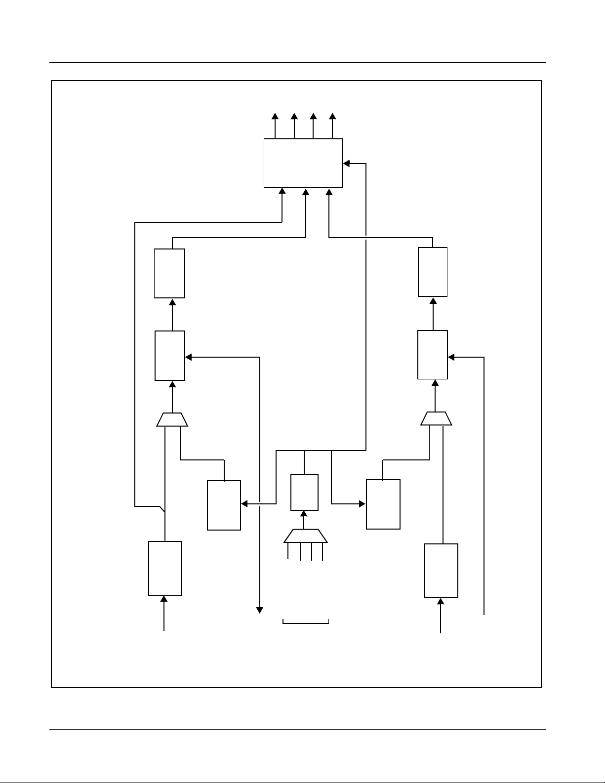
9392 Functional Description
(See Figure 1-1.) The 9392 allows LTC timecode (received either as SMPTE
embedded timecode or on an RS-485 LTC input) to be burned onto the active
video area and outputted over output SDI. The card can also burn up to 16
characters of static text onto the program video path.
Note: “Video channel” or “video path” in descriptions in this manual and on card GUI
controls refers to either of the two independent video paths accommodating
the two SDI inputs on the card. Each of these independent video channels
have independent timecode, text, and flat-field controls as described in this
manual. The two video channels are eventually outputted from the card via
the output crosspoint.
Independent, per-channel failover/manual select function provides for a
user-select able flat-f ield to repla ce program video ei ther as a manual se lection
or upon loss of input video. The generated flat field can be timed to input
video, or to a frame reference signal. Timecode burn-in and text can be sized
and positioned anywhere in the active video area using easy-to-use
positioning controls.
The 9392 also includes a 3x4 SDI output crosspoint, with
(channel A),
SDI OUT B (channel B), or recl ocked SDI IN A routable to up to
SDI OUT A
four SDI outputs.
T wo ind ependent RS-485 LTC inputs
(SDI B) are received by the card for each SDI channel. (The LTC inputs
RS-485 LTC IN (SDI A) and RS -485 LTC IN
received by the card must have the customary zero-crossing associated with
RS-485. If the LTC source is offset above or belo w ground (0 V), the sources
must be capacitively coupled or passed through an analog audio DA that can
restore zer o-crossing. )
Reference Function
The 9392 uses a common reference for both SDI video channels, with the
reference being selectable from
obtained from the frame references. This provides for proper rendering and
switchover transit io ns fro m pro gra m vid eo to the flat -f ield generators as well
as stable output video.
Note: Both program video inputs must be of the same refresh rate (e.g., 59.94 or
50, or co-related (29.97 or 25), and co-synchronous using frame sync or similar means. In practical application, both inputs should be frame-synchronized
using a common frame reference, with the same reference also to be used by
this card.
Input Video A, Input Video B, REF 1, or REF 2
9392-TCB-OM (V1.3) 93 92-T CB PRODUC T MAN UAL 1-5
Page 10
1 9392 Functional Description
1
2
3
4
SDI OUT
3G/HD/SD
Output
Crosspoint
SDI Drivers/
RCK A
PROC A
PROC B
9392BDV1.1LB66
Ident Text
Timecode
Burn-In
Burn-In
Burn-In
Ident Text
Burn-In
Timecode
RS-485 LTC I/O
Control
Manual/
Failover
Insertion
Control
Manual/
Failover
Insertion
RS-485 LTC I/O
PLL
Flat-Field
Generator
Select
Timing
Flat-Field
Generator
EQ
EQ/Reclock
Frame Ref 1
Input Video A
IN/OUT
SDI IN A
3G/HD/SD
RS-485 LTC A
Frame Ref 2
Input Video B
Reference
IN/OUT
SDI IN B
3G/HD/SD
RS-485 LTC B
Figure 1-1 9392 Functional Block Diagram
1-6 9392-TCB PRODUCT MANUAL 9392-TCB-OM (V1.3)
Page 11

Introduction 9392 Functional Description
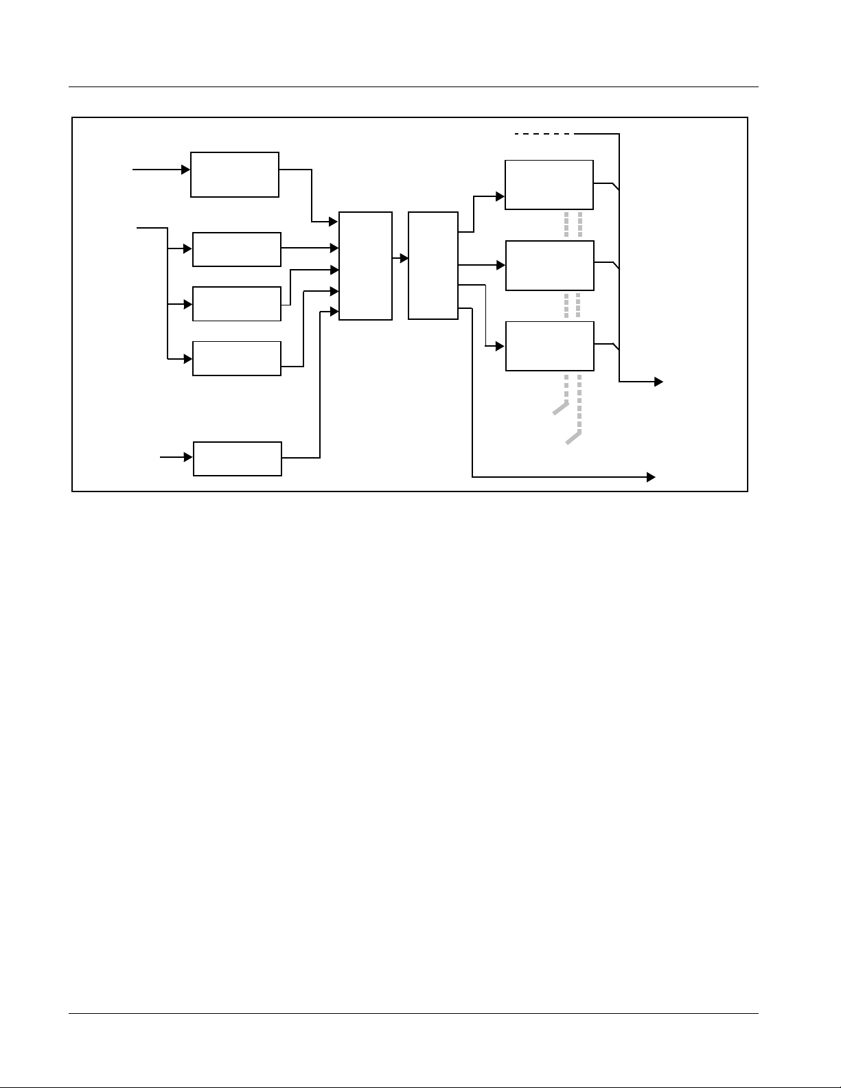
Timecode Burn-In and SDI Output Insertion
(See Figure 1-2.) This fun ct ion provi de s for ext rac ti on of time code data fro m
the input video, and in turn re-insertion of timecode data into the output SDI.
Note: Two independent timecode processors (one for each video path) are provided
as described here.
The function can monitor the SDI video inputs of the card for supported
timecode formats and convert the timecode to either or both ATC_LTC or
ATC_VITC for HD, and ATC_VITC or VITC waveform (with selectable odd/
even field line number control) for SD inputs. VITC waveform received on
the frame reference can be used as a source for all supported video formats.
Priority can be set to choose a particular received timecode format among a ny
received.
The card can also can receive LTC timecode from either of two RS-485 ports
for insertion as SMPTE embedded timecode formats onto the output video as
described above. A free-run generator selection provides a self-generated
timecode that can also be s et a s a cou nt- down t imec ode , wit h selectable wrap
or halt upon reaching zero.
The timecode burn-in function allows input video SMPTE embedded or
RS-485 LTC as burn-in timecode in any of the following formats:
• seconds
• seconds : frame
• seconds : frame : field
Note: In the above selections, hours : minutes are always present.
The vertical/horizontal positioning and size of the timecode burn-in can be
user-configured.
9392-TCB-OM (V1.3) 93 92-T CB PRODUC T MAN UAL 1-7
Page 12
1 9392 Functional Description
HD/SD–SDI
Frame
Reference
SDI
Video
Input
RS-485 LTC IN
Ref VITC
Waveform
Detect/Extract
SDI VITC
Detect/Extract
SDI ATC_VITC
Detect/Extract
SDI ATC_LTC
Detect/Extract
Audio LTC
Select
Priority/
Select
Buffer/
Format
SDI VITC
Timecode
Proc/Embed
ATC_VITC
Timecode
Proc/Embed
ATC_LTC
Timecode
Proc/Embed
Insert
Control
Line
Number
Control
Figure 1-2 Timecode Processor (One of Two Video Paths Shown)
Identification Text Burn-In
HD/SD–SDI
Video Output
RS-485 LTC OUT
Two independent text burn-in functions allow up to 16 ASCII-character text
to be burned onto the output video. Insertion is manually and independently
available for each SDI channel. The text burn function, when enabled, burns
the entered text whether the card channel is passing input video or an
internally generated flat field.
Flat-Field Generators
Independent flat-field generators are provided for each SDI channel. Either
manually selected or via failover on loss of SDI input, the generators are
individually configurable to output a flat field, with nine choices of color
being user selectable.
Video Output Crosspoint
A 3x4 video output crosspoint allows processed SDI Channel A, processed
SDI Channel B, or reclocked input channel SDI A to be outputted to any of
four SDI output BNC connectors.
1-8 9392-TCB PRODUCT MANUAL 9392-TCB-OM (V1.3)
Page 13
Introduction 9392 Functional Description
User Control Interface
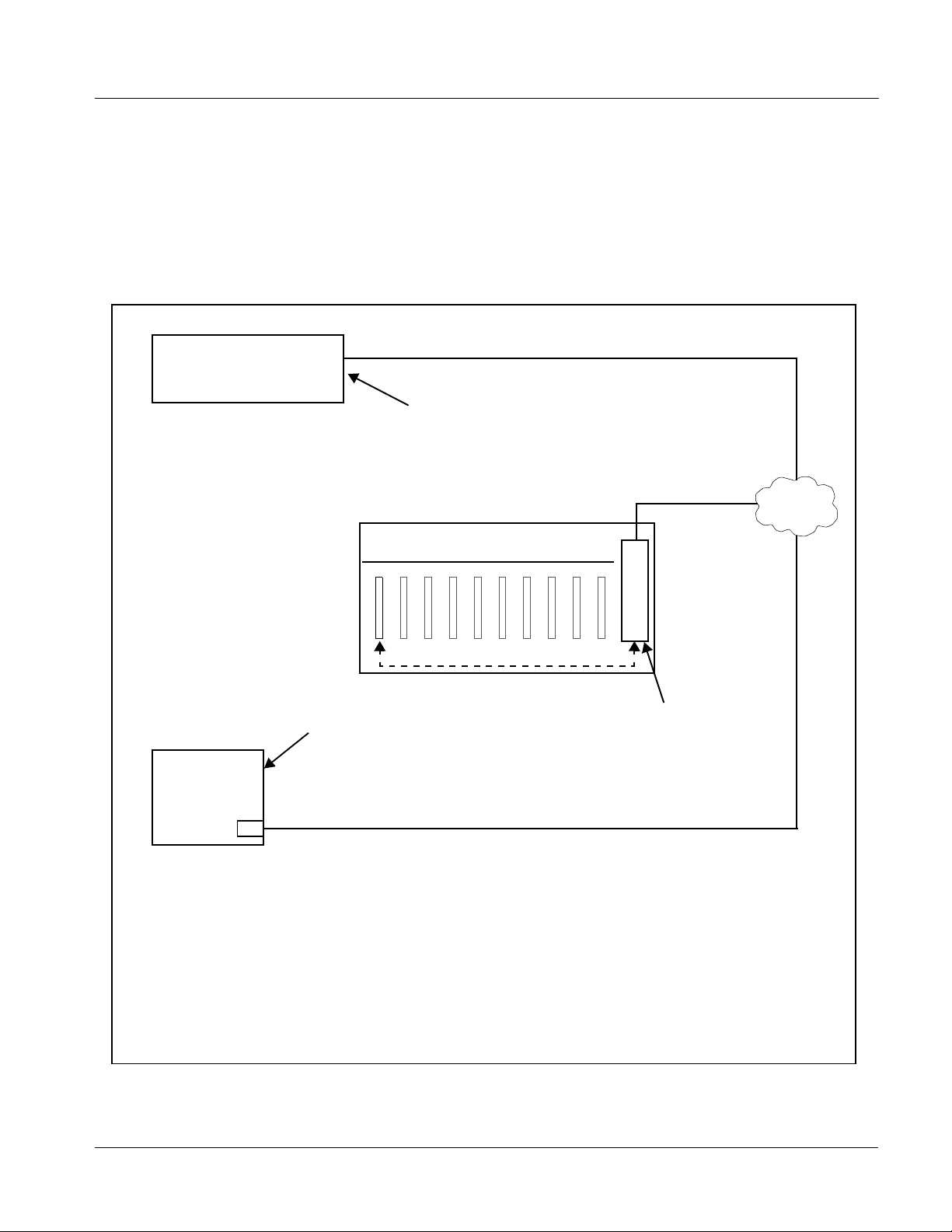
Figure 1-3 shows the user control interface options for the 9392. These
interfaces are individually described below.
Note: All user control interfaces described here are cross-compatible and can oper-
ate together as desired. Where applicable, any control setting change made
using a particular user interface is reflected on any other connected interface.
OGCP-9000 Control Panel
OGCP-9000/CC Control Panel
Computer
with NIC
or
DashBoard™ Remote Control
Using a computer with
DashBoard™ installed, 9392
card can be remotely controlled
over a LAN
Remote Control Panel
Using the Control Panel, 9392
card can be remotely controlled
over a LAN
LAN
20-Slot Frame with Network Controller card
In conjunction with a frame equipped
with a Network Controller card, 9392
card can be remotely controlled over
a LAN
Note: • To communicate with DashBoard™ or a Remote Control Panel, the frame must have a Network
Controller card installed.
• DashBoard™ and the Remote Control Panels provide network control of the 9392 as shown. The
value displayed at any time on the card, or via DashBoard™ or a Control Panel is the actual value
as set on the card, with the current value displayed being the actual value as effected by the card.
Parameter changes made by any of these means are universally accepted by the card (for
example, a change made using DashBoard™ controls will change the setting displayed on both
DashBoard™ and a Control Panel; a change made using a Control Panel will similarly change the
setting displayed on the Control Panel and DashBoard™).
Figure 1-3 9392 User Control Interface
9392-TCB-OM (V1.3) 93 92-T CB PRODUC T MAN UAL 1-9
Page 14

1 9392 Functional Description
• DashBoard™ User Interfa ce – Using DashBoard™, the 9392 and
other cards installed in openGear
1
®
frames such as the Cobalt®
HPF-9000 or 8321 Frame can be controlled from a computer and
monitor.
DashBoard™ allows users to view all frames on a network with
control and monitoring for all populated slots inside a frame. This
simplifies the setup and use of numerous modules in a large
installation and offers the ability to centralize monitoring. Cards
define their controllable parameters to DashBoard™, so the control
interface is always up to date.
The DashBoard™ software can be downloaded from the Cobalt
Digital Inc. website: www.cobaltdigital.com
(enter “DashBoard” in
the search window). The DashBoard™ user interface is described in
Chapter 3,“Operating Instructions”.
Note: If network remote control is to be used for the frame and the frame has not yet
been set up for remote control, Cobalt
User Guide (PN 9000RCS-RM) provides thorough information and
step-by-step instructions for setting up network remote control of COMPASS
and FUSION3G
OGCP-9000/CC Remote Control Panel product manuals have complete
instructions for setting up remote control using a Remote Control Panel.)
Download a copy of this guide by clicking on the Support>Documents>
Reference Guides link at www.cobaltdigital.com and then select DashBoard
Remote Control Setup Guide as a download, or contact Cobalt
Contact Cobalt Digital Inc. (p. 1-14).
®
cards using DashBoard™. (Cobalt® OGCP-9000 and
®
reference guide Remote Control
®
as listed in
®
• Cobalt
®
OGCP-9000, OGCP-9000/CC and WinOGCP Remote
Control Panels – The OGCP-9000, OGCP-9000/CC, and WinOGCP
Remote Control Panels conveniently and intui ti vel y provi de
parameter monitor and c ontrol of the cards within the 20-slot f rame.
The remote control panels allow quick and intuitive access to
hundreds of cards in a fa ci lity, and can monitor a nd al l ow adj ust ment
of multiple p arameters at one time.
The remote control panels are totally compatible with the openGear
®
control software DashBoard™; any changes made with either system
are reflected on the other.
1. openGear® is a registered trademark of Ross Video Limited. DashBoard™ is a trademark of Ross
Video Limited.
1-10 9392-TCB PRODUCT MANUAL 9392-TCB-OM (V1.3)
Page 15

Introduction Technical Specifications
9392 Rear Modules
The 9392 physically inte rfaces to sy stem video and audio con necti ons using a
Rear Module.
All inputs and outputs shown in the bl ock diagr am (Figure 1-1) ente r and exit
the card via the card edge backplane connector. The Rear Module breaks out
the 9392 card edge connections to industry standard connections that
interface with other components and systems in the signal chain.
9392 Rear Modules are shown and described in Chapter 2, “Installation and
Setup”.
Technical Specifications
Table 1-1 lists the technical specifications for the 9392-TCB 3G/HD/SD-SDI
Dual-Channel Timecode Burn-In Inserter card.
Table 1-1 Technical Specifica tions
Item Characteristic
Part number, nomenclature 9392-TCB 3G/HD/SD-SDI Dual-Channel Timecode Burn-In Inserter
Installation/usage environment Intended for installation and usage in frame meeting openGear®
Power consumption < 25 Watts
Environmental:
Operating temperature:
Relative humidity (operating or storage):
Frame communication 10/100 Mbps Ethernet with Auto-MD IX.
Standards supported 3G: SMPTE 425 level A and B
Internally generated flat-field formats
Note:Flat-field format is user-selectable using GUI
controls and independent of received (input video)
format
modular system definiti on.
32° – 104° F (0° – 40° C)
< 95%, non-condensing
1080p60, 1080p59.94, 1080p50
HD: 1080i60, 1080i59.94, 1080i50, 1080p29.97, 1080p25, 1080p24;
1080p23.98
720p60, 720p59.94, 720p50, 720p29.97, 720p25, 720p24,
720p23.98
SD: 486i59094, 576i50
3G: 1080p59.94, 1080p50
HD: 1080i59.94, 1080i50, 1080psf23.98
720p59.94, 720p50
SD: 525i59.94, 625i50
9392-TCB-OM (V1.3) 93 92-T CB PRODUC T MAN UAL 1-11
Page 16

1 Technical Specifications
Table 1-1 Technical Specifications — continued
Item Characteristic
BNC SDI Video Inputs/Out puts Input/O utput Complement:
• SDI inputs: (2) 75Ω BNC
• SDI outputs: (4) 75Ω BNC via 3x4 crosspoint
Data Rates Supported:
SMPTE 425 level A: 3 Gbps
SMPTE 292 HD-SDI: 1.485 Gbps or 1.485/1.001 Gbps
SMPTE 259M-C SD-SDI: 270 Mbps
BNC Connector Input/Output Impedance:
75 Ω terminating
Cable Equalization (3G):
394 ft (120 m) Belden 1694A
Cable Equalization (HD):
591 ft (180 m) Belden 1694A
Cable Equalization (SD):
1050 ft (320 m) Belden 1694A
Return Loss:
> 15 dB up to 1.485 GHz
> 10 dB up to 2.970 GHz
Jitter; Alignment (3G / HD / SD):
< 0.3 UI / 0.2 UI / 0.2 UI
Jitter; Timing (3G / HD / SD):
< 2.0 UI / 1.0 UI / 0.2 UI
Processing delay Less than 25 samples
Frame reference inputs Standards Supported:
SMPTE 170M/318M (“black burst”)
SMPTE 274M/296M (“tri-color”)
Return Loss:
> 35 dB up to 5.75 MHz
RS-485 Ports Two ports, each 3-wire RS-485 using Phoenix connectors with
removable screw terminal blocks (Phoenix PN 1803581; Cobalt PN
5000-0013-000R)
1-12 9392-TCB PRODUCT MANUAL 9392-TCB-OM (V1.3)
Page 17

Introduction Warranty and Service Information
Warranty and Service Information
Cobalt Digital Inc. Limited Warranty
This product is warranted to be free from defects in material and workmanship for a period of five (5)
years from the date of shipment to the original purchaser, except that 4000, 5000, 6000, 8000 series
power supplies, and Dolby
material and workmanship for a period of one (1) year.
Cobalt Digital Inc.'s (“Cobalt”) sole obligation under this warranty sh all be limited to, at its option, (i)
the repair or (ii) replacement of the produc t, and the det ermination of whether a defect is covered under
this limited warranty shall be made at the sole discretion of Cobalt.
This limited warrant y appl ies on ly t o the origi nal end-pu rchaser of the produ ct, and i s not assign able o r
transferrable therefrom. This warr ant y i s li mited to defects in material and workmanship, and shall not
apply to acts of God, accidents, or negligence on behalf of the purchaser, and shall be voided upon the
misuse, abuse, alteration, or modification of the product. Only Cobalt authorized factory
representatives are authorized to make repairs to the product, and any unauthorized attempt to repair
this product shall immediately void the warranty. Please contact Cobalt Technical Support for more
information.
®
modules (where applicable) are warranted to be free from defects in
To facilitate the resolut ion of warranty related issues, Cobalt recommends registering the product by
completing and returning a product registration form. In the event of a warrantable defect, the
purchaser shall notify Cobalt with a descripti on of the problem, and Cobalt shall provide the purchaser
with a Re turn Mate rial Auth oriz ation (“RMA”). For retu rn, defective product s should be double boxed,
and sufficiently protecte d, in the original packa ging, or equivalent, a nd shipped to the Coba lt Factory
Service Center, postage prepaid and insured for the purchase price. The purchaser should include the
RMA number, description of the problem encountered, date purchased, name of dealer purchased
from, and serial number with the shipment.
Cobalt Digital Inc. Factory Service Center
2406 E. University Avenue Office: (217) 344-1243
Urbana, IL 61802 USA Fax: (217) 344-1245
www.cobaltdigital.com Email: info@cobaltdigital.com
THIS LIMITED WARRANTY IS EXPRESSLY IN LIEU OF ALL OTHER WARRANTIES
EXPRESSED OR IMPLIED, INCLUDING THE WARRANTIES OF MERCHANTABIL ITY AND
FITNESS FOR A PARTICULAR PURPOSE AND OF ALL OTHER OBLIGATIONS OR
LIABILITIES ON COBALT'S PART. ANY SOFTWARE PROVIDED WITH, OR FOR USE WITH,
THE PRODUCT IS PROVIDED “AS IS.” THE BUYER OF THE PRODUCT ACKNOWLEDGES
THAT NO OTHER REPRESENTATIONS WERE MADE OR RELIED UPON WITH RESPECT TO
THE QUALITY AND FUNCTION OF THE GOODS HEREIN SOLD. COBALT PRODUCTS ARE
NOT AUTHORIZED FOR USE IN LIFE SUPPORT APPLICATIONS.
COBALT'S LIABILITY, WHETHER IN CONTRACT, TORT, WARRANTY, OR OTHERWISE, IS
LIMITED TO THE REPAIR OR REPLACEMENT, AT ITS OPTION, OF ANY DEFECTIVE
PRODUCT, AND SHALL IN NO EVENT INCLUDE SPECIAL, INDIRECT, INCIDENTAL, OR
CONSEQUENTIAL DAMAGES (INCLUDING LOST PROFITS), EVEN IF IT HAS BEEN
ADVISED OF THE POSSIBILITY OF SUCH DAMAGES.
9392-TCB-OM (V1.3) 93 92-T CB PRODUC T MAN UAL 1-13
Page 18

1 Contact Cobalt Digital Inc.
Contact Cobalt Digital Inc.
Feel free to contact our thorough and professional support representative s for
any of the following:
• Name and address of your local dealer
• Product information and pricing
• Technical support
• Upcoming trade show in formation
Phone: (217) 344-1243
Fax: (217) 344-1245
Web: www.cobaltdigital.com
General Information: info@cobaltdigital.com
Technical Support: support@cobaltdigital.com
1-14 9392-TCB PRODUCT MANUAL 9392-TCB-OM (V1.3)
Page 19

Overview
Chapter 2
Chapter 2 Installation and Setup
This chapter contains the following information:
• Installing the 9392 Into a Frame Slot (p. 2-1)
• Installing a Rear Module (p. 2-3)
• Connecting To 3-Wire Phoenix Terminal Connectors (p. 2-5)
• Setting Up 9392 Network Remote Control (p. 2-6)
Note: The 9392 is suitable for installation only in a 20-slot frame (Cobalt® PN
HPF-9000, OG3-FR, or 8321).
Installing the 9392 Into a Frame Slot
CAUTION
Heat and power distribution requirements within a frame may dictate specific
slot placement of cards. Cards with many heat-producing compon ents should
be arranged to avoid areas of excess heat build-up, particularly in frames
using only convection cooling. The 9392 has a high power dissipation (<25 W
max.). As such, avoiding placing the card adjacent to other cards with similar
dissipation values if possible.
CAUTION
This device contains semiconductor devices which are
susceptible to serious damage from Electrostatic
Discharge (ESD). ESD damage may not be immediately
apparent and can affect the long-term reliability of the
device.
Avoid handling circuit boards in high static environments
such as carpeted areas, and when wearing synthetic fiber
clothing. Always use proper ESD handling precautions
and equipment when working on circuit boards and
related equipment.
9392-TCB-OM (V1.2) 9392-TCB PRODUCT MANUAL 2-1
Page 20

2 Installing the 9392 Into a Frame Slot
CAUTION
If required, make certain Rear Module(s) is installed before installing the 9392
into the frame slot. Damage to card and/or Rear Module can occur if module
installation is attempted with card already installed in slot.
Note: Check the packaging in which the 9392 was shipped for any extra items such
as a Rear Module connection label. In some cases, this label is shipped with
the card and to be installed on the Rear I/O connector bank corresponding to
the slot location of the card.
Install the 9392 into a frame slot as follows:
1. Determine the slot in which the 9392 is to be installed.
2. Open the frame front access panel.
3. While holding the card by the card edges, align the card such that the
plastic ejector tab is on the bottom.
4. Align the card with the top and bottom guides of the slot in which the
card is being installed. Gradually slide the card into the slot. When
resistance is noticed, gently continue pushing the card until its rear
printed circuit edge terminals engage fully into the Rear Module mating
connector.
CAUTION
If card resists fully engaging in Rear Module mating connector, check for
alignment and proper insertion in slot tracks. Damage to card and/or Rear
Module may occur if improper card insertion is attempted.
Verify that the card is fully engaged in Rear Module mating connector.
5.
6. Close the frame front access panel.
7. Connect cabling in accordance with the appropriate diagram shown in
Table 2-1, “9392 Rear Modules” (p. 2-4).
8. Repeat steps 1 through 7 for other 9392 cards.
Notes: • The 9392 BNC inputs are internally 75-ohm terminated. It is not necessary
to terminate unused BNC inputs or outputs.
• External frame sync reference signals are received by the card over a
reference buses on the card frame, and not on any card rear I/O module
connectors. The frame has a BNC connectors labeled REF 1 and REF 2
which receive reference signals from an external source such as a house
distribution.
9. If network remote control is to be used for the frame and the f rame has
not yet been set up for remote control, perform setup in accordance with
Setting Up 9392 Network Remote Control (p. 2-6).
2-2 9392-TCB PRODUCT MANUAL 9392-TCB-OM (V1.2)
Page 21

Installation and Setup Installing a Rear Module
Note: If installing a card in a frame already equipped for, and connected to
DashBoard™, no network setup is required for the card. The card will be discovered by DashBoard™ and be ready for use.
Installing a Rear Module
Notes: • This procedure is applicable only if a Rear Module is not currently
installed in the slot where the 9392 is to be installed.
• Note that some Rear Modules and labels have several ventilation holes. To
allow maximum ventilation, it is recommended to place the label fully over
connectors such that label is flush with rear module and holes are not
obscured. Also, when a card is not installed in a slot, it is recommended that
the supplied blank cover be used to preserve proper forced ventilation
flow-through.
9392 Rear Modules are shown and described in 9392 Rear Modules (p. 2-4).
Install a Rear Module as follows:
1. On the frame, determine the slot in which the 9392 is to be installed.
2. In the mounting area corresponding to the slot location, install
Rear Module as shown in Figure 2-1.
DSCN3483A.JPG
DSCN3487A.JPG
Align and engage mounting tab on Rear
I/O Module with the module seating slot
1
on rear of frame chassis.
Hold top of Rear Module flush against
frame chassis and start the captive screw.
2
Lightly tighten captive screw.
Figure 2-1 Rear Module Installation
9392-TCB-OM (V1.2) 93 92-T CB PRODUC T MAN UAL 2-3
Page 22

2 Installing a Rear Module
9392 Rear Modules
Table 2-1 shows and describes the full assortment of Rear Modules
specifically for use with the 9392.
Notes: • Rear Modules equipped with 3-wire Phoenix connectors are supplied with
removable screw terminal block adapters. For clarity, the adapters are omitted in the drawings below. Refer to Connecting To 3-Wire Phoenix Terminal
Connectors (p. 2-5) for connector polarity orientation details.
• The Rear Modules shown here are standard production items. Other signal
combinations may be available as custom items. Consult Product Support
with requests. Also, please check our web site pages for this product; new
Rear Modules may be available that are not listed here.
Table 2-1 9392 Rear Modules
9392 Rear Module Description
RM20-9392-D Rear Module Provid es the fol lowin g conne cti on s:
• Two 3G/HD/SD-SDI video input BNCs
(
SDI IN A and SDI IN B)
• Two RS-485 LTC input/outputs
L TC I/O B. LTS ports can be correlated to either SDI
video path.
• Four 3G/HD/SD-SDI video output BNCs
(
SDI OUT 1 thru SDI OUT 4). Output routing
assignments per card SDI Output Map GUI routing.
Note: Some rear module labels may label
SDI OUT 1 thru SDI OUT 4 as SDI OUT A
thru SDI OUT D, respectively.
LT C I/O A and
RM20-9392-E Rear Module
2-4 9392-TCB PRODUCT MANUAL 9392-TCB-OM (V1.2)
Page 23

Installation and Setup Connecting To 3-Wire Phoenix Terminal Connectors
Connecting To 3-Wire Phoenix Terminal Connectors
Figure 2-2 shows connections to the card 3-wire Phoenix™ terminal block
connectors. These connectors are used for card RS-485 LTC input/output
connections. These terminal blocks use a removable screw terminal binding
post block which allows easier access to the screw terminals.
Note: It is preferable to wire connections to Phoenix plugs oriented as shown in
Figure 2-2
that the orientation of rear module connectors is not necessarily consistent
within a rear module, or between different rear modules. If wiring is first connected to Phoenix plug oriented as shown here, the electrical orientation will
be correct regardless of rear module connector orientation.
Note: An RS-485 input received by the card must have the customary zero-crossing
associated with RS-485. If the LTC source is offset above or below ground
(0 V), the sources must be capacitively coupled or passed through an analog
audio DA that can restore zero-crossing.
rather than assessing polarity on rear module connectors. Note
Rear module
PCB connector
RS-485
RS-485 LTC Port Connections
Removable Phoenix plug view oriented
with top (screw terminal s ) up
Note: RS-485 communication will not work if
any of the connections are reversed from
that shown here.
A (-) B (+) G
Figure 2-2 3-Wire Phoenix Terminal Connections
9392-TCB-OM (V1.2) 93 92-T CB PRODUC T MAN UAL 2-5
Page 24

2 Setting Up 9392 Network Remote Control
Setting Up 9392 Network Remote Control
Perform remote control setup in accordance with Cobalt® reference guide
“Remote Control User Guide” (PN 9000RCS-RM).
Note: • If network remote control is to be used for the frame and the frame has not
yet been set up for remote control, Cobalt
Control User Guide (PN 9000RCS-RM) provides thorough information and
step-by-step instructions for setting up network remote control of
COMPASS™ cards using DashBoard™. (Cobalt
OGCP-9000/CC Remote Control Panel product manuals have complete
instructions for setting up remote control using a Remote Control Panel.)
Download a copy of this guide by clicking on the
Support>Documents>Reference Guides link at www.cobaltdigital.com
and then select DashBoard Remote Control Setup Guide as a download, or
contact Cobalt
• If installing a card in a frame already equipped for, and connected to
DashBoard™, no network setup is required for the card. The card will be discovered by DashBoard™ and be ready for use.
®
as listed in Contact Cobalt Digital Inc. (p. 1-14).
®
reference guide Remote
®
OGCP-9000 and
2-6 9392-TCB PRODUCT MANUAL 9392-TCB-OM (V1.2)
Page 25

Overview
Chapter 3
Chapter 3 Operating Instructions
This chapter contains the following information:
If you are already familiar with
using DashBoard to control
Cobalt cards, please skip to
9392 Function Submenu List
and Descriptions (p. 3-8).
• Control and Display Descriptions (p. 3-1)
• Accessing the 9392 Card via Remote Control (p. 3-5)
• Checking Card Information (p. 3-7)
• 9392 Function Submenu List and Descriptions (p. 3-8)
• Troubleshooting (p. 3-18)
Control and Display Descriptions
This secti on describes the user interface controls, indicators, and displays for
using the 9392 card. The 9392 function s can be acces sed and contr olle d using
any of the user interfaces described here.
The format in which the 9392 functional controls, indicators, and displays
appear and are used varies depending on the user interface being used.
Regardless of the user interface being used, access to the 9392 functions (and
the controls, ind icato rs, an d disp lays r elat ed to a particul ar f uncti on) fo llows a
general arrangement of Function Submenus under which related controls can
be accessed (as described in Function Submenu/Parameter Submenu
Overview below).
After familiarizing yourself with the arrangement described in Function
Submenu/Parameter Submenu Overview, proceed to DashBoard™ User
Interface (p. 3-4).
Note: When a setting is changed, settings displayed on DashBoard™ are the
settings as effected by the 9392 card itself and reported back to the remote
control; the value displayed at any time is the actual value as set on the card.
9392-TCB-OM (V1.3) 9392-TCB PRODUCT MANUAL 3-1
Page 26

3 Control and Display Descriptions
Function Submenu/Parameter Submenu Overview
The functions and related pa rameters avai lable on the 9392 car d are organ ized
into function submenus, which consist of parameter groups as shown below.
Figure 3-1 shows how the 9392 card an d its submenus ar e orga nized, and also
provides an overview of how navig ation is performed be tween cards, func tion
submenus, and parameters.
If using DashBoard™, the desired 9392 card is first selected.
9392
Submenu a Submenu b
Individual Parameters
Each submenu consists of groups of parameters
related to the function submenu. Using the “Video
Path A” function submenu example, the individual
parameters for this function consist of variou s items
and parameters such as Timecode Burn enable, and
so on.
Figure 3-1 Function Submenu/Parameter Submenu Overvie w
• • •
The desired function submenu is next
selected.
Function Submenus consist of parameter
groups related to a particular 9392 card
function (for example, “Video Path A”).
Submenu z
3-2 9392-TCB PRODUCT MANUAL 9392-TCB-OM (V1.3)
Page 27

Operating Instructions Control and Display Descriptions
9392 Card Edge Controls, Indicators, and Display
Figure 3-2 shows and describes the 9392 card edge controls, indicators, and
display.
4-Character Alphanumeric Display
SD
HD
Input Format
MENU DEPTH
Indicators
Menu Depth
Indicators
3G
REF
ERR
RMT
Card Edge Manual Controls
9392
LOCK
Status
Indicators
Item Function
Display Displays 4-digit abbreviated code showing menu and submenu selections. When in a menu displaying a
Card Edge
Manual
Controls
Input Format
Indicators
Menu Depth
Indicators
RMT LED Blue LED flashes when 9392 is receiving control message from remote network control
parameter setting, the display shows parametric scalar value (and +/- sign where applicable).
This function is currently reserved.
Three blue LEDs indicate the input signal format being received and locked onto by the 9392:
• 3G
• HD
• SD
Continuous cycling of the LEDs indicates the 9392 has not locked onto a particular format (as in the case of no
signal input).
This function is currently reserved.
REF LED Blue LED illuminates when 9392 is receiving valid framesync when set up for framesync reference.
LOCK LED Blue LED illuminates when 9392 unable to lock to framesync, or unable to lock to input standard.
ERR LED This function is currently reserved.
Figure 3-2 9392 Card Edge Controls, Indicators, and Display
9392-TCB-OM (V1.3) 93 92-T CB PRODUC T MAN UAL 3-3
Page 28

3 Control and Display Descriptions
DashBoard™ User Interface
(See Figure 3-3.) The 9392 functi on submenus are or ganiz ed in DashBoard ™
using tabs (for example, “Video Path A” in Figure 3-3). When a tab is
selected, each parametric control or selection list item ass ociated with the
function is displayed. Scalar (numeric) parametric values can then be adjusted
as desired using the GUI slider controls. Items in a list can then be selected
using GUI drop-down lists.
Select top-level menu item
Video Path A
Set FLAT
FIELD Enable
to Disabled
Set TIME CODE BURN
to burn timecode in
sec:frames:field
In this example, the
Video P a th A tab is selected to disable flat-field
insertion, and enable timecode burn of hr:min:sec:frame:field for the video
path A SDI input.
Figure 3-3 DashBoard™ Setup of Example Video Path A Setup
3-4 9392-TCB PRODUCT MANUAL 9392-TCB-OM (V1.3)
Page 29

Operating Instructions Accessing the 9392 Card via Remote Control
Accessing the 9392 Card via Remote Control
Access the 9392 card using DashBoard™ as described below.
Accessing the 9392 Card Using DashBoard™
1. On the computer connected to the frame LAN, open DashBoard™.
2. As shown be low (in the left side Basic View Tree) locate the Network
Controller Card asso ci ated wi th th e fra me co ntain ing th e 9392 c ard t o be
accessed (in this example, “MFC-8320-N SN: 00108053”).
DB_ACCESS1.PNG
3. As shown below, expand the tree to access the cards within the frame.
Click on the card to be accessed (in this example, “Slot 6: 9392”).
.
DB_ACCESS2A.PNG
As shown on the next page, when the card is accessed in DashBoard™
its function submenu scree n showing ta bs for eac h functi on is disp layed.
(The particular submenu screen displayed is the previously displayed
screen from the last time the card was accessed by DashBoard™).
9392-TCB-OM (V1.3) 93 92-T CB PRODUC T MAN UAL 3-5
Page 30

3 Accessing the 9392 Card via Remote Control
Card Access/Navigation
Tree Pane
Card Info
Pane
Card Function Submenu
and Controls Pane
3-6 9392-TCB PRODUCT MANUAL 9392-TCB-OM (V1.3)
Page 31

Operating Instructions Checking Card Information
Checking Card Information
The operating st atus and s oftwar e ver sion the 9 392 car d can be chec ked us ing
DashBoard™. Figure 3-4 shows and describes the 9392 card information
screen using DashBoard™.
Note: Proper operating status in DashBoard™ is denoted by green icons for the
status indicators shown in Figure 3-4. Yellow or red icons respectively
indicate an alert or failure condition. Refer to Troubleshooting (p. 3-18) for
corrective action.
The Tree View shows the cards seen by DashBoard™.
In this example, Network Controller Card MFC-8320-N
(serial number ...8053) is hosting a 9392 card in slot 18.
Status Displays
Clicking the Status sub-tab shows the status the signal being
received by the 9392, and other card conditions. Green
Settings icon shows that any changes made on DashBoard™
are sucessfully saved on the card’s memory.
Clicking the Product sub-tab shows product information such
as card model, options installed, and firmware versions. Use
this information when communicating to Cobalt
card.
®
regarding the
9392_CARD_INFO.PNG
Figure 3-4 9392 Card Info Utility
9392-TCB-OM (V1.3) 93 92-T CB PRODUC T MAN UAL 3-7
Page 32

3 9392 Function Submenu List and Descriptions
9392 Function Submenu List and Descriptions
T able 3- 1 indivi dually l ists an d descri bes each 9 392 funct ion subme nu (“tab”)
and its rela ted list selections, controls, and parameters. Where helpful,
examples showing usage of a function are also provided. Table 3-1 is
primarily based upon using DashBoard™ to access each function and its
corresponding submenus and parameters.
Note: All numeric (scalar) parameters displayed on DashBoard™ can be changed
using the slider controls, arrows, or by numeric keypad entry in the
corresponding numeric field. (When using numeric keypad entry , add a return
after the entry to commit the entry.)
On DashBoard™ itself and in Table 3-1, the function submenu items are
organized using ta bs as shown below.
Some functions use sub-tabs to help maintain clarity and organization. In these
instances, Table 3-1 shows the ordinate tab along with its sub-tabs. Highlighted
sub-tabs indicate that controls described are found by selecting this sub-tab (in
this example, the Master Controls sub-tab on the Video Path A page).
The table below provides a quick-reference to the page numbers where each
function submenu item can be found.
Function Submenu Item Page
Video Path Controls
Reference Select Control
LTC Port Configuration Controls
Video Output Crosspoint Control
3-9
3-16
3-17
3-17
3-8 9392-TCB PRODUCT MANUAL 9392-TCB-OM (V1.3)
Page 33

Operating Instructions 9392 Function Submenu List and Descriptions
Table 3-1 9392 Function Submenu List
Accesses the flat field generator, timecode burn-in, text
burn-in, and timecode generator (self-generate) controls
for Video Path A card input.
Video Path Controls
Note: Video Path B has controls identical to the controls described here for Video Path A. Therefore, only the Video Path A
controls are shown here.
• Flat Field Insertion Cont r ols
• Timecode Master Controls Provides controls for using either video or other external timecode source, or
Controls flat field insertion, failover insertion, and format as follows:
• Enable:
• Disable never replaces input video with flat field.
• Enable manually replaces input video with flat field (regardless or not if
input video is present).
• Enable on Loss of Video allows valid input video to pass, but fails over
to flat field upon loss of input video.
Note: Failover occurs when receiver module does not detect stable lock
for known formats supported by the card.
• Format selects the flat-field format when flat field is inserted onto video.
Choices are typical TV and film SD, HD, and 3G formats (refer to
Specifications in Chapter 1. Introduction for more information).
Note: When flat field is inserted (either manually or by failover), format
of flat field is always as set per this drop-down, and does not
automatically track with input video.
• Color allows flat field color selection of nine common colors.
• Status shows flat field insertion status, as well as status of input SDI on the
video path.
using the card TC Generator self-generated timecode.
• Free Run Timecode Controls Allows an initial (starting) count to be applied to output video timecode when
9392-TCB-OM (V1.3) 93 92-T CB PRODUC T MAN UAL 3-9
Free Run (TC Gen) insertion is enabled.
Note: • Initialization can only be applied when card is outputting Free Run
timecode (as shown by Output Status displaying “Free Run”).
• If failover to Free Run occurs due to loss of external timecode(s), the
Free Run count assumes its initial count from the last valid externally
supplied count.
Page 34

3 9392 Function Submenu List and Descriptions
Table 3-1 9392 Function Submenu List — continued
Provides controls to enable/disable timecode and text
burn-in, and also size and position the burn-ins.
• Timecode Burn-In Enable/Format Select Display control selects from the following modes:
• Disabled never inserts timecode burn-in on video.
• Seconds inserts burn-in timecode in hr:min:sec format.
• Seconds+Frame inserts burn-in timecode in hr:min:sec:frame format.
• Seconds+Frame+Field inserts burn-in timecode in
hr:min:sec:frame:field format.
Note: • Timecode insertion control burns-in timecode as set here on
received SDI video or manual/failover flat field.
• On progressive video where frame count exceeding 30 fps, the field
counter is utilized to show extended frame count as follows:
0.0 Frame 0
0.1 Frame 1
1.0 Frame 2
1.1 Frame 3
...
29.1 Frame 59
• Timecode Size/Position Controls Allows timecode burn-in size/position attributes control as follows:
• Horizontal Size sets horizontal size (in units of 11 lines x control setting;
e.g., control set for “4” results in horizontal size of 4 x 11 = 44).
(Range is 0 thru 15)
• Vertical Size sets vertical size (in units of 11 lines x control setting; e.g.,
control set for “4” results in horizontal size of 4 x 11 = 44).
(Range is 0 thru 15)
• Horizontal Position sets horizontal position (in percentage of offset from
left of image area, left justified).
(Range is 0 thru 100)
• Vertical Position sets vertical position (in percentage of offset from top of
image area, top justified).
(Range is 0 thru 100)
• Identification Text Burn-In Insertion Controls identification text insertion as follows:
• Display enables or disables text burn-in insertion.
• Burn Text dialog ent ry allows up to 16 ASCII characters to be entered as a
burn-in text string. Upper and lower case characters, as well as numeric
characters, can be entered.
Note: Ident Burn insertion control burns-in text as set here on received SDI
video or manual/failover flat field.
• Identification Text Size/Position Controls Allows text burn-in size/position attributes control as follows:
• Horizontal Size sets horizontal size (in units of 11 lines x control setting;
e.g., control set for “4” results in horizontal size of 4 x 11 = 44).
(Range is 0 thru 15)
• Vertical Size sets vertical size (in units of 11 lines x control setting; e.g.,
control set for “4” results in horizontal size of 4 x 11 = 44).
(Range is 0 thru 15)
• Horizontal Position sets horizontal position (in percentage of offset from
left of image area, left justified).
(Range is 0 thru 100)
• Vertical Position sets vertical position (in percentage of offset from top of
image area, top justified).
(Range is 0 thru 100)
3-10 9392-TCB PRODUCT MANUAL 9392-TCB-OM (V1.3)
Page 35

Operating Instructions 9392 Function Submenu List and Descriptions
Table 3-1 9392 Function Submenu List — continued
Provides timecode data extract ion from va rious sourc es ,
and provides formatting and re-insertion controls for
inserting the timecode into the output video and burn-in.
Shown below is an example in which received SDI video with SDI VITC waveform timecode is to be converted to SDI
ATC_VITC timecode data. Each Timecode control is fully described on the pages that follow. Timecode settings performed
here output selected timecode on output video and timecode burn-in. Video Path A and B have identical independent
controls.
525i 5994
w/ VITC
9392
Waveform
A
Noting that the incoming video contains VITC
525i 5994
w/ ATC_VITC
waveform timecode data (as shown in the status
display), set the Source Priority drop-down lists to
include VITC Waveform timecode data (SDI VITC) as
a choice. This extracts VITC Waveform timecode
data from the incoming video.
In this example, it is desired to provide SD ATC_VITC
B
timecode data in the output video. As such, set
SD ATC VITC Insertion to Enabled.
In the example here, the line numbers are set to the
default SMPTE 12M-2-2008 recommended value.
Reference VITC
Detect/Extract
525i SDI
w/ VITC
Waveform
SDI VITC
Detect/Extract
A
A
Priority/
Select
Buffer/
Format
RS-485 LTC
SDI VITC
Timecode
Proc/Embed
ATC_VITC
Timecode
Proc/Embed
B
SDI ATC_VITC
Detect/Extract
ATC_LTC
Timecode
Line
Number
Control
Proc/Embed
ATC_VITC Insertion = Enabled
ATC_VITC = Line 13 (default SMPTE 12M-2)
525i SDI
w/ATC_VITC
SDI ATC_LTC
Detect/Extract
Free Run
(Internal Co unt)
RS-485 LTC
Detect/Insert
9392-TCB-OM (V1.3) 93 92-T CB PRODUC T MAN UAL 3-11
Insert
Control
Page 36

3 9392 Function Submenu List and Descriptions
Table 3-1 9392 Function Submenu List — continued
(continued)
• Timecode Source Status Displays Displays the current status and contents of the supported external timecode
• LT C Input Control
• Mute LTC Control Allows RS-485 LTC output to mute upon loss of selected timecode inputs.
formats shown to the left.
• I f a format is receiving timecode data, the current content (timecode
running count and line number) is displayed.
• I f a format is not receiving timecode data, Not Present is displayed.
Selects source (RS-485 port LTC A or LTC B) to be used by card to receive
LTC.
Note: • Input LTC must be appropriately set for card to receive and process
received LTC.
• LTC Port Configuration controls must be set to use port selected
here as an input to receive RS-485 LTC. See LTC Port Configuration
Controls (p. 3-17).
• Card LTC inputs will not center inputs with DC offset. If input has DC
offset, the source may need to be capacitively coupled to remove the
offset.
• W hen set to Enabled and input timecode is lost, RS-485 LTC output goes
to frozen state.
• When set to Disabled and input timecode is lost RS-485 LTC output keeps
counting, with count value being free-run count.
Note: If muting upon loss of a particular input format is desired, set all
Source Priority 1 thru 4 to that particular input format. If this is not
done, the card failover timecode selection may substitute another
format choice for the format not being received.
• Incoming ATC Packet Removal Control Enables or disables removal of existing input video AT C timecode packets
from the output. This allows removal of undesired existing timecodes from
the output, resulting in a “clean slate” where only desired timecodes are then
re-inserted into the output. (For example, if both SDI ATC_VITC and
ATC_LTC are present on the input video, and only AT C_LTC is desired,
using the Removal control will remove both timecodes from the output. The
ATC_LTC timecode by itself can then be re-inserted on the output using the
other controls discussed here.)
3-12 9392-TCB PRODUCT MANUAL 9392-TCB-OM (V1.3)
Page 37

Operating Instructions 9392 Function Submenu List and Descriptions
Table 3-1 9392 Function Submenu List — continued
(continued)
• Source Priority Selects the priority assigned to each supported external formats, and
internal Free Run in the event the preferred source is unavailable.
Source Priority 1 thru Source Priority 4 select the preferred format to be
used in descending order (i.e., Source Priority 2 selects the second-most
preferred format, and so on. See example below.)
HD/SD
525i
Input VITC
(1st priority)
•
•
•
Reference VITC
(2nd priority)
In this example, In pu t VITC 1st priority selection selects SDI VITC (received on
SDI input) over reference VITC (received on frame reference) regardless of video
input material source to be proce ssed by the card.
The selected timecode source is embedded on the SDI video output (in this
example, 720p) using the selected line number. In this example, if the SDI VITC
on the SDI input becomes unavailable, the card then uses the reference VITC
data received on the frame reference.
Note: Reference VITC selection uses reference source as selected on the
Reference tab (see Reference Select Control (p. 3-16)).
SDI IN
TC
FRAME REF
SDI
OUT
525i
(w/ ATC_VITC)
Note:Disable Output setting should be used with care. If Disable Output is selected with alternate intended format(s) set as a lower
priority, the card will indeed disable all timecode output should the ordinate preferred format(s) become unavailable.
Typically, choices other than Disable should be used if a timecode output is always desired, with Disable only being used to
remove all timecode data.
In this example, even though
and ATC_LTC could be
available to substitute for
ATC_VITC not being present,
the card will revert to no
The choices shown here
will allow ATC_LTC to
“out-prioritize” Disable
Output if ATC_VITC is
not available.
timecode output since the
choice of Disable Output
“out-prioritizes” ATC_LTC
with these settings.
• Offset Controls Allows the current timecode count to be advanced or delayed on the output
video.
• Offset Advance or Delay selects offset advance or delay.
• Offset Field delays or advances or delays timecode by one field.
• Offset Frame delays or advances or delays timecode by up to 5
frames.
Note: Default settings are null, with both controls set at zero as shown.
9392-TCB-OM (V1.3) 93 92-T CB PRODUC T MAN UAL 3-13
Page 38

3 9392 Function Submenu List and Descriptions
Table 3-1 9392 Function Submenu List — continued
(continued)
• Output Stat us Dis play Displays the current content and source being used for the timecode data as
• SD VITC Waveform Insertion Controls For SD output, enables or disables SD VITC waveform timecode insertion
follows:
• O utput status OK (in this example, SDI VITC timecode received and
outputted).
• Timecode Insertion button set to Disabled; output insertion disabled.
Note: • If timecode is not available from Source Priority selections
performed, timecode on output reverts to Free Run (internal count)
mode.
• Because the 1’s digit of the display Frames counter goes from 0 to
29, the fractional digit (along with the 1’s digit) indicates frame count
as follows:
0.0 Frame 0
0.1 Frame 1
1.0 Frame 2
1.1 Frame 3
•
•
•
29.1 Frame 59
into the output video, and selects the VITC1 and VITC2 line numbers (6 thru
22) where the VITC waveform is inserted.
Note: • If only one output line is to be used, set both controls for the same
line number.
• SD VITC Waveform Insertion control only affects VITC waveforms
inserted (or copied to a new line number) by this function. An existing
VITC waveform on an unscaled SD SDI stream is not affected by this
control and is passed on an SDI output.
• SD ATC Insertion Control For SD output, enables or disables SD ATC_VITC timecode insertion into
the output video, and selects the line number for ATC_VITC.
3-14 9392-TCB PRODUCT MANUAL 9392-TCB-OM (V1.3)
Page 39

Operating Instructions 9392 Function Submenu List and Descriptions
Table 3-1 9392 Function Submenu List — continued
(continued)
• HD ATC_LTC Insertion Control For HD output, enables or disables ATC_LTC timecode insertion into the
• HD ATC_VITC Insertion Control
• ATC_VITC Legacy Support Control When enabled, accommodates equipment requiring ATC_VITC packet in
output video, and selects the line number for ATC_LTC timecode data.
For HD output, enables or disables ATC_VITC timecode insertion into the
output video, and selects the line number for ATC_VITC1 and ATC_VITC2.
Note: If only one output line is to be used, set both controls for the same line
number.
both fields as a “field 1” packet (non-toggling).
Note: Non-toggling VITC1 and VITC2 packets do not conform to
SMPTE 12M-2-2008 preferences. As such, ATC_VITC Legacy
Support should be enabled only if required by downstream
equipment.
9392-TCB-OM (V1.3) 93 92-T CB PRODUC T MAN UAL 3-15
Page 40

3 9392 Function Submenu List and Descriptions
Table 3-1 9392 Function Submenu List — continued
Provides a master reference selection for both SDI video
channels.
Reference Select Control
• Reference Select Control Selects a master reference source for both video paths as shown.
Note: • Both program video inputs must be of the same refresh rate (e.g.,
59.94 or 50, or co-related (29.97 or 25), and co-synchronous using
frame sync or similar means. In practical application, both inputs
should be frame-synchronized using a common frame reference,
with the same reference also to be used by this card.
• Reference Selection control must be appropriately set to match
upstream video signal timing:
- If input video is not locked to a frame reference, the 9392 should
be set to lock to the respective input choice (SDI A or SDI B).
- If the video input is locked to a frame reference, the 9392 should
be set to same reference.
• Free Run selection should only be used when no SDI inputs are to
be used. This selection is valid only for internally generated flat field
outputs.
• A DashBoard Reference Status indication is provided that alerts to
a missing reference where a reference has been selected. However,
the status indication will not detect improper reference usage
violating the conditions specified above.
Shown below are appropriate selections of this control for various examples.
In this example, because both inputs
are upstream frame synced to frame
Reference 1, 9392 can be set for ref
from either SDI input or Reference 1
(however, in this case safest operation
is to use Reference 1).
Note: 9392 Ref 1 or Ref 2 selection
should only be used when
SDI A
SDI B
Frame Ref 1
525i 5994
720p 5994
Frame
Sync
upstream video is also locked to
the same reference.
In this example, because SDI IN B is not
frame synced to frame Reference 1,
when SDI IN B is used the 9392 should
be set to ref from the SDI IN B input
SDI A
SDI B
525i 5994
720p 5994
video.
Frame Ref 1
In this example, the 9392 is generating
an internal flat field. Since no external
timing need be associated with the flat
field, the Free Run (internal) setting
can be used.
However, if an external frame
reference is available, it is safest to
use the external Ref 1 or Ref 2 setting
as appropriate.
Frame Ref 1
Frame
Sync
Frame
Sync
SDI IN A
9392
SDI IN B
SDI IN A
9392
SDI IN B
SDI IN A
X
SDI IN B
X
9392
3-16 9392-TCB PRODUCT MANUAL 9392-TCB-OM (V1.3)
Page 41

Operating Instructions 9392 Function Submenu List and Descriptions
Table 3-1 9392 Function Submenu List — continued
Provides controls for setting RS-485 ports for LTC in or
LTC Port Configuratio n Contr ols
out functions.
• LTC Port Direction Controls Sets RS-485 LTC port functions to either receive LTC over the port (Input),
or send RS-485 LTC over the port (Out).
Note: LTC A and LTC B (as inputs) are independent of either video path,
with either port being used to receieve RS-485 LTC as desired. As
an output, LTC A Encoder and LTC B Encoder correspond to Video
Path A and Video Path B, respectively.
Provides a 3 x 4 output video crosspoint between the two
video paths (and reclocked SDI In A input) to up to four
Video Output Crosspoint Co ntr ol
• Output Video Crosspoint As shown below, each independent card SDI output SDI 1 Out thru SDI 4
SDI output ports.
Out can receive as sources:
• Processed A (video path A with processing as described in Video Path
Controls (p. 3-9).
• Processed B (video path B with processing as described in Video Path
Controls (p. 3-9).
• Input A Reclock
Note: Crosspoint is fully flexible, with duplicated choices (DA function)
across several outputs from the same or different sources.
In this example:
• Processed A (video path from input SDI In A) is DA’ed to outputs SDI 1 Out and SDI 2 Out.
• Input A Reclock is outputted on SDI 3 Out.
• Processed B (video path from input SDI In B) is outputted to SDI 4 Out.
9392-TCB-OM (V1.3) 93 92-T CB PRODUC T MAN UAL 3-17
Page 42

3 Troubleshooting
Troubleshooting
This section provides general troubleshooting information and specific
symptom/corrective action for the 9392 card and its remote control interface.
The 9392 card requires no periodic maintenance in its normal operation; if
any error indication (as described in this section) occurs, use this section to
correct the condition.
Error and Failure Indicator Overview
The 9392 card itself and its remote control systems all (to varying degrees)
provide error and failure indications. Depending on how the 9392 card is
being used (i.e, standalone or network controlled through DashBoard™,
check all available indications in the event of an error or failure condition.
The various 9392 card and remote control error and failure indicators are
individually described below.
Note: The descriptions below provide general information for the various status and
error indicators. For specific failures, also use the appropriate subsection
listed below.
• Basic Troubleshooting Checks (p. 3-22)
• 9392 Processing Error Troubleshooting (p. 3-22)
• Troubleshooting Network/Remote Control Errors (p. 3-24)
3-18 9392-TCB PRODUCT MANUAL 9392-TCB-OM (V1.3)
Page 43

Operating Instructions Troubleshooting
9392 Card Edge Status/Error Indicators and Display
Figure 3-5 shows and describes the 9392 card edge status indicators and
display. These indicators and the display show status and error conditions
relating to the card itself and remote (network) c ommunications (where
applicable). Because these indicators are part of the card itself and require no
external interface, the indicators are particularly useful in the event of
communications problems with external devices such as network remote
control devices.
4-Character Alphanumeric Display
SD
HD
Input Format
MENU DEPTH
Indicators
Menu Depth
Indicators
3G
REF
ERR
RMT
Card Edge Manual Controls
9392
LOCK
Status
Indicators
Item Function
Display Displays 4-digit abbreviated code showing menu and submenu selections. When in a menu displaying a
Card Edge
Manual
Controls
Input Format
Indicators
Menu Depth
Indicators
RMT LED Blue LED flashes when 9392 is receiving control message from remote network control.
parameter setting, the display shows parametric scalar value (and +/- sign where applicable).
This function is currently reserved.
Three blue LEDs indicate the input signal format being received and locked onto by the 9392:
• 3G
• HD
• SD
Continuous cycling of the LEDs indicates the 9392 has not locked onto a particular format (as in the case of no
signal input).
This function is currently reserved.
REF LED Blue LED illuminates when 9392 is receiving valid framesync when set up for framesync reference.
LOCK LED Blue LED illuminates when 9392 unable to lock to framesync, or unable to lock to input standard.
ERR LED This function is currently reserved.
Figure 3-5 9392 Card Edge Status Indicators and Display
9392-TCB-OM (V1.3) 93 92-T CB PRODUC T MAN UAL 3-19
Page 44

3 Troubleshooting
DashBoard™ Status/Error Indicators and Displays
Figure 3-6 shows and describes the DashBoard™ status i ndicators and
displays. These indicator icons and displays show status and error conditions
relating to the 9392 card itself and remote (network) communications.
Indicator Icon or Display Error Description
Red indicator icon in Card Access/Navigation Tree pane shows card with Error
condition (in this example, the Card Access/Navigation Tree pane shows a general
error issued by the 9392 card in slot 6).
Specific errors are displayed in the Card Info pane (in this example “No connection
to device” indicating 9392 card is not connecting to frame/LAN).
If the 9392 card is not connecting to the frame or LAN, all controls are grayed-out.
Gray indicator icon in Card Access/Navigation Tree pane shows card(s) are not
being seen by DashBoard™ due to lack of connection to frame LAN (in this
example, both a 9392 card in slot 6 and the MFC-8320-N Network Controller Card
for its frame in slot 0 are not being seen).
Yellow indicator icon in Card Access /Navigation Tree pane shows card with Alert
condition (in this example, the Card Access/Navigation Tree pane shows a general
alert issued by the MFC-8320-N Network Controller Card).
Clicking the card slot position in the Card Access/Navigation Tree (in this example
Network Controller Card “Slot 0: MFC-8320-N”) opens the Card Info pane for the
selected card. In this example, a “Fan Door Open” specific error is displayed.
Yellow indicator icon in 9392 Card Info pane shows error alert, along with cause for
alert (in this example, the 9392 is not receiving external LTC for the respective video
channel, and has reverted to free-run timecode burn-in.
Figure 3-6 DashBoard™ Status Indicator Icons and Displays
3-20 9392-TCB PRODUCT MANUAL 9392-TCB-OM (V1.3)
Page 45

Operating Instructions Troubleshooting
Access the Card Inf o pane fo r a speci fic car d by clic king the c ard slot positio n
in the Card Access/Navigation Tree pane (as shown in the example in Figure
3-7).
By clicking on “Slot 0: MFC-8320-N”
in this example, Card Info is
displayed for frame Network
Controller Card
By clicking on “Slot 18: 9392”
in this example, Card Info is
shown for 9392 card in slot 18
Status for selected card is
shown here (in this
example, connection OK
and “Fan Door Open”
alert)
Card general information
is displayed in lower
portion of Card Info pane
Status for selected
card is shown here
Where applicable,
additional status is
displayed (as shown in
this example)
Figure 3-7 Selecting Specific Cards for Card Info Status Display
9392-TCB-OM (V1.3) 93 92-T CB PRODUC T MAN UAL 3-21
Page 46

3 Troubleshooting
Basic Troubleshooting Checks
Failures of a general nature (affecting many cards and/or functions
simultaneously), or gross inoperability errors are best addressed first by
performing basic checks before proceeding further. Table 3-2 provides basic
system checks that typically locate the source of most general problems. If
required and applicable, perform further troubleshooting in accordance with
the other troubleshooting tables in this section.
Table 3-2 Basic Troubleshooting Checks
Item Checks
Verify for power presence On both the frame Network Controller Card and the 9392, in all cases when power is
being properly supplied there is always at least one indicator illuminated. Any card
showing no illuminated indicators should be cause for concern.
Check Cabl e connection
secureness and connecting
points
Card seating within slots Make certain all cards are properly seated within its frame slot. (It is best to assure
Check status indicators and
displays
Troubles hoot by substitution All cards within the frame can be hot-swapped, replacing a suspect card or module
Make certain all ca ble connec tions are ful ly secure (inc luding coa xial cable att ach ment
to cable ferrules on BNC connectors). Also, make certain all connecting points are as
intended. Make certain the selected connecting points correlate to the intended card
inputs and/or outputs. Cabling mistakes are especially easy to make when working
with large I/O modules.
proper seating by ejecting the card and reseating it again.)
On both DashBoard™ and the 9392 card edge indicators, red indications signify an
error condition. If a st atus indic ator sig nifies an error, proceed to the following tables in
this section for further action.
with a known-good item.
9392 Processing Error Troubleshooting
Table 3-3 provides 9392 processing troubleshooting information. If the 9392
card exhibits any of the symptoms listed in Table 3-3, follow the
troubleshooting instructions provided.
In the majority of cases, most errors are caused by simple errors where the
9392 is not appropriately set for the type of signal being received by the card.
Note: The error indications shown below are typical for the corresponding error
conditions listed. Other error indications not specified here may also be
displayed on DashBoard™ and/or the 9392 card edge status indicators.
Note: Where errors are displayed on both the 9392 card and network remote
controls, the respective indicators and displays are individually described in
this section.
3-22 9392-TCB PRODUCT MANUAL 9392-TCB-OM (V1.3)
Page 47

Operating Instructions Troubleshooting
Table 3-3 Troubleshooting Processing Errors by Symptom
Symptom Error/Condition Corrective Action
• DashBoard™ shows Video
yellow icon and Input Invalid
message in 9392 Card Info
pane.
• Card edg e Input Format LEDs
show continuous cycling.
• DashBoard™ shows invalid
in Ref St atus m essa ge in 9392
Card Info pane.
Transient video or audio errors
(CRC, etc.) noted in viewing or
on logging waveform monitor.
No video input present Make certain intended video source is
connected to appropriate 9392 card video
input. Make certain BNC cable connections
between frame Rear I/O Module for the card
and signal source are OK.
Reference not properly
selected or not being received
(card has reverted to free-run
failover)
Card reference cannot sync
with received video input.
If external reference is n ot intended to be u sed,
make certain the Reference selection list is set
to appropriate alternate selection as desired.
Reference Selection control must be
appropriately set to match upstream video
signal timing:
• If input video is not locked to a frame
reference, the 9392 should be set to lock to
the respective input choice (SDI A or SDI B).
• If the video input is locked to a frame
reference, the 9392 should be set to lock to
the same reference (Reference 1 or
Reference 2).
Note: Both program video inputs m ust be of the
same refresh rate (e.g., 59.94 or 50, or
co-related (29.97 or 25), and
co-synchronous using frame sync or
similar means. In practical application,
both inputs should be
frame-synchronized us ing a common
frame reference, with the same
reference also to be used by this card.
RS-485 LTC not being locked on
to by card (yellow status
indicator)
ERROR displayed on Timecode
Output Status.
9392-TCB-OM (V1.3) 93 92-T CB PRODUC T MAN UAL 3-23
• LTC RS-485 polarity
incorrect
• LTC RS-485 does not have
zero-crossing per RS-485
convention.
Free-run selected as prioritized
manual selection, but timecode
generator is set to bypass
• Make certain RS-485 LTC connections are
as described in Connecting To 3-Wire
Phoenix Terminal Connectors (p. 2-5) in
Chapter 2, Installation and Setup.
• The RS-485 input s received by the ca rd must
have the customary zer o-crossing ass ociated
with RS-485. If the LTC source is offset
above or below ground (0 V), the sources
must be capacitively coupled or passed
through an analog audio DA that can restore
zero-crossing.
If free-run timecode is set as first prioritized
selection (i.e., free-run over any other choice),
Timecode Passthrough on Video Path >
Master Controls must be set to TC Gen On.
Page 48

3 Troubleshooting
Troubleshooting Network/Remote Control Errors
Refer to Cobalt® reference guide “COMPASS™ Remote Control User
Guide” (PN 9000RCS-RM) for network/remote control troubleshooting
information.
In Case of Problems
Should any problem arise with this product that was not solved by the
information in this section, please contact the Cobalt Digital Inc. Technical
Support Department.
If required, a Return Material Authorization number (RMA) will be issued to
you, as well as specific shipping instructions. If required, a temporary
replacement item will be made available at a nominal charge. Any shipping
costs incurred are the customer’s responsibility. All products shipped to you
from Cobalt Digital Inc. will be shipped collect.
The Cobalt Digital Inc. Technical Support Department will continue to
provide advice on any product manufactured by Cobalt Digital Inc., beyond
the warranty period without charge, for the life of the product.
See Contact Cobalt Digital Inc. (p. 1-14) in Chapter 1, “Introduction“ for
contact in formation.
3-24 9392-TCB PRODUCT MANUAL 9392-TCB-OM (V1.3)
Page 49

Page 50

Cobalt Digital Inc.
2406 E. University Ave.
Urbana, IL 61802
Voice 217.344.1243 • Fax 217.344.1245
www.cobaltdigital.com
9392-TCB-OM (V1.3) Printed in USA
 Loading...