

Page 1
9374-EMDE
Quad SDI Stream
9372-EMDE
9371-EMDE
Dual SDI Stream
Single SDI Stream
SDI – AES – MADI
Embedder / De-embedder
Product Manual
Cobalt Digital Inc.
2406 E. University Ave.
Urbana, IL 61802
Voice 217.344.1243 • Fax 217.344.1245
www.cobaltdigital.com
937X-OM (V1.3)
Page 2

Copyright
©Copyright 2013, Cobalt Digital Inc. All Rights Reserved.
Duplication or distribution of this manual and any information contained within is strictly prohibited without the express written
permission of Coba lt Digital Inc. This manual and a ny information contained within, may not be re produced, distribute d, or
transmitted in any form, or by any means, for any purpose, without the express written permission of Cobalt Digital Inc.
Reproduction or reverse engineering of software used in this device is prohibited.
Disclaimer
The information in this document has been carefully examined and is believed to be entirely reliable. However, no responsibility
is assumed for inaccuracies. Furthermore, C obalt Digit al Inc. res erves the right to ma ke changes to any pro ducts herein to improve
readability, function, or design. Cobalt Digital Inc. does not assume any liability arising out of the application or use of any
product or circuit described herein.
Trademark Information
Cobalt® is a registered trademark of Cobalt Digital Inc.
COMPASS
openGear
Dolby
property of their respective owners.
®
and FUSION3G® are registered trademarks of Cobalt Digital Inc.
®
is a registered trademark of Ross Video Limited. DashBoard™ is a trademark of Ross Video Limited. Dolby®
®
is a registered trademark of Dolby Laboratories, Inc. Other product names or trademarks appearing in this manual are the
®
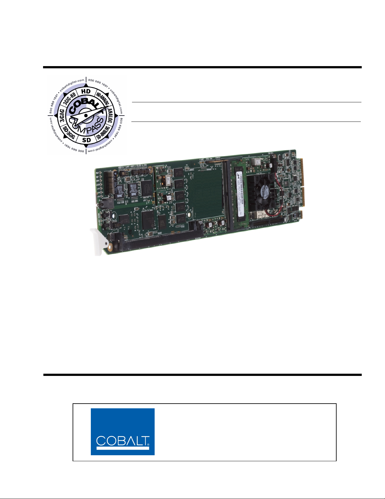
Congratulations on choosing the Cobalt
full line of modular processing and conversion gear for broadcast TV environments. The Cobalt Digital Inc. line
includes video decoders and encoders, audio embedders and de-embedders, distribution amplifiers, format converters,
remote control syst ems and mu ch more. S hould you have qu estions pe rtaining to the inst allation o r operatio n of you r
card, please contact us at the contact information on the front cover.
9374 series of MADI Embedders/De-embedders . The 9374-series is part of a
Manual No.: 937X-OM
Document Version: V1.3
Release Date: August 7, 2013
Description of
product/manual
changes:
- Update manual to reflect latest functionality
additions including timecode functions and option
+LTC (audio/RS-485 LTC I/O).
937X-OM (V1 .3)
Page 3

Table of Contents
Chapter 1 Introduction . . . . . . . . . . . . . . . . . . . . . . . . . . . . . . . . . . . . . . . . . . . 1-1
Overview ................................................................................................................ 1-1
9374-Series Card Software Versions and this Manual........................................... 1-2
Cobalt Reference Guides........................................................................................ 1-2
Manual Conventions............................................................................................... 1-3
Warnings, Cautions, and Notes .................................................................. 1-3
Labeling Symbol Definitions...................................................................... 1-4
Safety Summary ..................................................................................................... 1-4
Warnings..................................................................................................... 1-4
Cautions...................................................................................................... 1-4
9374-Series Cards Functional Description............................................................. 1-5
9374-Series Input/Output Formats ............................................................. 1-5
Audio Crosspoint/Processing Description.................................................. 1-6
User Control Interface .............................................................................. 1-11
9374-Series Card Rear Modules............................................................... 1-12
Audio and Video Formats Supported by the 9374-Series Cards.............. 1-13
Technical Specifications....................................................................................... 1-14
Warranty and Service Information ....................................................................... 1-17
Cobalt Digital Inc. Limited Warranty....................................................... 1-17
Contact Cobalt Digital Inc.................................................................................... 1-18
Chapter 2 Installation and Setup . . . . . . . . . . . . . . . . . . . . . . . . . . . . . . . . . . . 2-1
Overview ................................................................................................................ 2-1
Installing the 9374-Series Card Into a Frame Slot ................................................. 2-1
Installing a Rear Module ........................................................................................ 2-3
9374-Series Card Rear Modules................................................................. 2-4
9374-Series Analog Audio Output....................................................................... 2-10
Setting Up 9374-Series Card Network Remote Control ...................................... 2-10
937X-OM (V1.3) 9374-SERIES PRODUCT MANUAL i
Page 4

Chapter 3 Operating Instructions . . . . . . . . . . . . . . . . . . . . . . . . . . . . . . . . . . . 3-1
Overview................................................................................................................. 3-1
Control and Display Descriptions........................................................................... 3-1
Function Submenu/Parameter Submenu Overview .................................... 3-2
9374-Series Card Edge Controls, Indicators, and Display.......................... 3-3
DashBoard™ User Interface ....................................................................... 3-4
Accessing the 9374-Series Card via Remote Control............................................. 3-5
Accessing the 9374-Series Card Using DashBoard™................................ 3-5
Checking Card Information..................................................................................... 3-7
Considerations Regarding Multiple-Channel SDI.................................................. 3-8
9374-Series Function Submenu List and Descriptions........................................... 3-9
Input Meters ............................................................................................. 3-10
Output Meters ........................................................................................... 3-11
SDI Audio Crosspoint .............................................................................. 3-12
MADI Crosspoint ..................................................................................... 3-13
AES/Analog Audio Crosspoint ................................................................ 3-14
Crosspoint QuickRoute ............................................................................ 3-15
Tone Generators ....................................................................................... 3-16
Flat Field Generators ................................................................................ 3-16
Reference Select ....................................................................................... 3-17
Gain Controls ........................................................................................... 3-18
Timecode .................................................................................................. 3-19
Presets ...................................................................................................... 3-29
Troubleshooting .................................................................................................... 3-30
Error and Failure Indicator Overview....................................................... 3-30
Basic Troubleshooting Checks.................................................................. 3-34
9374-Series Processing Error Troubleshooting......................................... 3-34
Troubleshooting Network/Remote Control Errors.................................... 3-36
In Case of Problems .................................................................................. 3-36
ii 9374-SERIES PRODUCT MANUAL 937X-OM (V1.3)
Page 5

Overview
Chapter 1
Chapter 1 Introduction
Note: This manual covers the 9374-Series, which consists of the 9374, 9372, and
9371 cards. These cards vary only in the number of SDI channels supported;
the differences are described where applicable.
This manual provides installati on and o per at ing instr uct ions for the
9374-Series of SDI-AES-MADI Embedder/De-embedders (also referred to
herein as the 9374-Series card).
This manual consists of the following chapters:
• Chapter 1, “Introduction” – Provid es informati on about this manual
and what is covered. Als o pr ovi des general information re gar di ng the
9374-Series cards.
• Chapter 2, “Installation and Setup” – Provides instructions for
installing the 9374-Series card in a frame, and optionally installing
Rear Modules for the card.
• Chapter 3, “Operating Instructions” – Provides overviews of
operating controls and instructions for using the 9374-Series cards.
This chapter contains the following information:
• 9374-Series Card Software Versions and this Manual (p. 1-2)
• Cobalt Reference Guides (p. 1-2)
• Manual Conventions (p. 1-3)
• Safety Summary (p. 1-4)
• 9374-Series Cards Functional Description (p. 1-5)
• Technical Specifications (p. 1- 14)
• Warranty and Service Information (p. 1-17)
• Contact Cobalt Digital Inc. (p. 1-18)
937X- OM (V1.3) 9374-SERIES PRODUCT MANUAL 1-1
Page 6

1 9374-Series Card Software Versions and this Manual
9374-Series Card Software Versions and this Manual
When applicable, Cobalt Digital Inc. provides for continual product
enhancements through software updates. As such, functions described in this
manual may pertain specifically to cards loaded with a particular software
build.
The Software Version of your card can be checked by viewing the Ca r d I n fo
menu in DashBoard™. See Checking Car d I nfo rmat ion (p. 3-7) in Chapter 3,
“Operating Instructi ons” for mor e information. You can then ch eck our
website for the latest software version currently released for the card as
described below.
Check our website and proceed as follows if your card’s software does not
match the latest versi on:
Card Software earlier than
latest version
Card Software newer than
version in manual
Card is not loaded with the latest software. Not all
functions and/or specified performance described in
this manual may be available.
You can update your card with the new Update
software by going to the Support>Firmware link at
www.cobaltdigital.com. Download “Firmware
Update Guide”, which provides simple instructions
for downloading the latest firmware for your card
onto your computer, and then uploading it to your
card through DashBoard™.
Software updates are field-installed without any
need to remove the card from its frame.
A new manual is expediently released whenever a
card’s software is updated and specifications
and/or functionality have changed as compared
to an earlier version (a new manual is not
necessarily released if specifications and/or
functionality have not changed). A manual earlier
than a card’s software version may not completely
or accurately describe all functions available for
your card.
If your card shows features not described in this
manual, you can check for the latest manual (if
applicable) and download it by going to the
Support>Documents>Product Information and
Manuals link at www.cobaltdigital.com.
Cobalt Reference Guides
From the Cobalt® web home page, go to Support>Documents>Reference
Guides
updates, and other topics.
1-2 9374-SERIES PRODUCT MANUAL 937X-OM (V1.3)
for easy to use guide s covering network remot e control , card fir mware
Page 7
Introduction Manual Conventions
Manual Conventions
In this manual, display messages and connectors are shown using the exact
name shown on the card itself. Examples are provided below.
• Card-edge display messages are shown like this:
Ch01
• Connector names are shown like this: AES 8
In this manual, the terms below are applicable as follows:
• 937X or 9374-Series refers to the 9374-Series of SDI-AES-MADI
Embedder/De-embedders.
Warnings, Cautions, and Notes
Certain items in this manual are highlighted by special messages. The
definitions are provided bel ow.
Warnings
• Frame refers to the 8321 (or similar) 20-slot frame that houses the
• Device and/or Card refers to a COMPASS
Cobalt
®
COMPASS® and/or FUSION3G® cards.
®
and/or FUSION3G®
card.
• System and/or Video System refers to the mix of interconnected
production and terminal equipment in which the 9374-Series cards
and other COMPASS
• Functions and/or features that are available only as an option are
®
and/or FUSION3G® cards operate.
denoted in th is manual like this:
Not all options are covered in this manual. In these cases, Manual
Supplement(s) for the option(s) ordered have been included in the
binder containing this manual.
Warning messages indicate a possible hazard which, if not avoided, could
result in pe rsonal injury or death.
Cautions
Caution messages indicate a problem or incorrect practice which, if not
avoided, could result in improper operation or damage to the product.
Notes
Notes provide supplemental information to the accompanying text. Notes
typically precede the text to which they apply.
937X- OM (V1.3) 9374-SERIES PRODUCT MANUAL 1-3
Page 8
1 Safety Summary
Labeling Symbol Definitions
Attention, consult accompanying documents.
Electronic device or as sembly is susceptible to damage from an ESD event.
Handle only using appropriate ESD prevention practices.
If ESD wrist strap is not available, handle card only by edges and avoid contact
with any connectors or components.
Symbol (WEEE 2002/96/EC)
For product disposal, ensure the following:
• Do not dispose of this product as unsorted municipal waste.
• Collect this product separately.
• Use collection and return systems available to you.
Safety Summary
Warnings
! WARNING !
Cautions
CAUTION
CAUTION
CAUTION
CAUTION
CAUTION
T o redu ce risk of electr ic shock do not remove line voltage service barrier cover on frame
equipment containing an AC power supply. NO USER SERVICEABLE PARTS INSIDE.
REFER SERVICING TO QUALIFIED SERVICE PERSONNEL.
This device is intended for environmentally controlled use only in appropriate video
terminal equipment operating environments.
This product is intended to be a component product of an openGear® frame. Refer to the
frame Owner's Manual for important safety instr uctions regarding the proper installation
and safe operation of the frame as well as its component products.
Heat and power distribution requirements within a frame may dictate specific slot
placement of cards. Cards with many heat-producing components should be arranged to
avoid areas of excess heat build-up, particularly in frames using only convection cooling.
The 9374-Series cards have a moderate power dissipation (20 W max.). As such, avoiding
placing the card adjacent to other cards with similar dissipation values if possible.
If required, make certain Rear Module(s) is installed before installing the card into the
frame slot. Damage to card and/or Rear Module can occur if module installation is
attempted with card already installed in slot.
If card resists fully engaging in Rear Module mating connector, check for alignment and
proper insertion in slot tracks. Damage to card and/or Rear Module may occur if improper
card insertion is attempted.
1-4 9374-SERIES PRODUCT MANUAL 937X-OM (V1.3)
Page 9

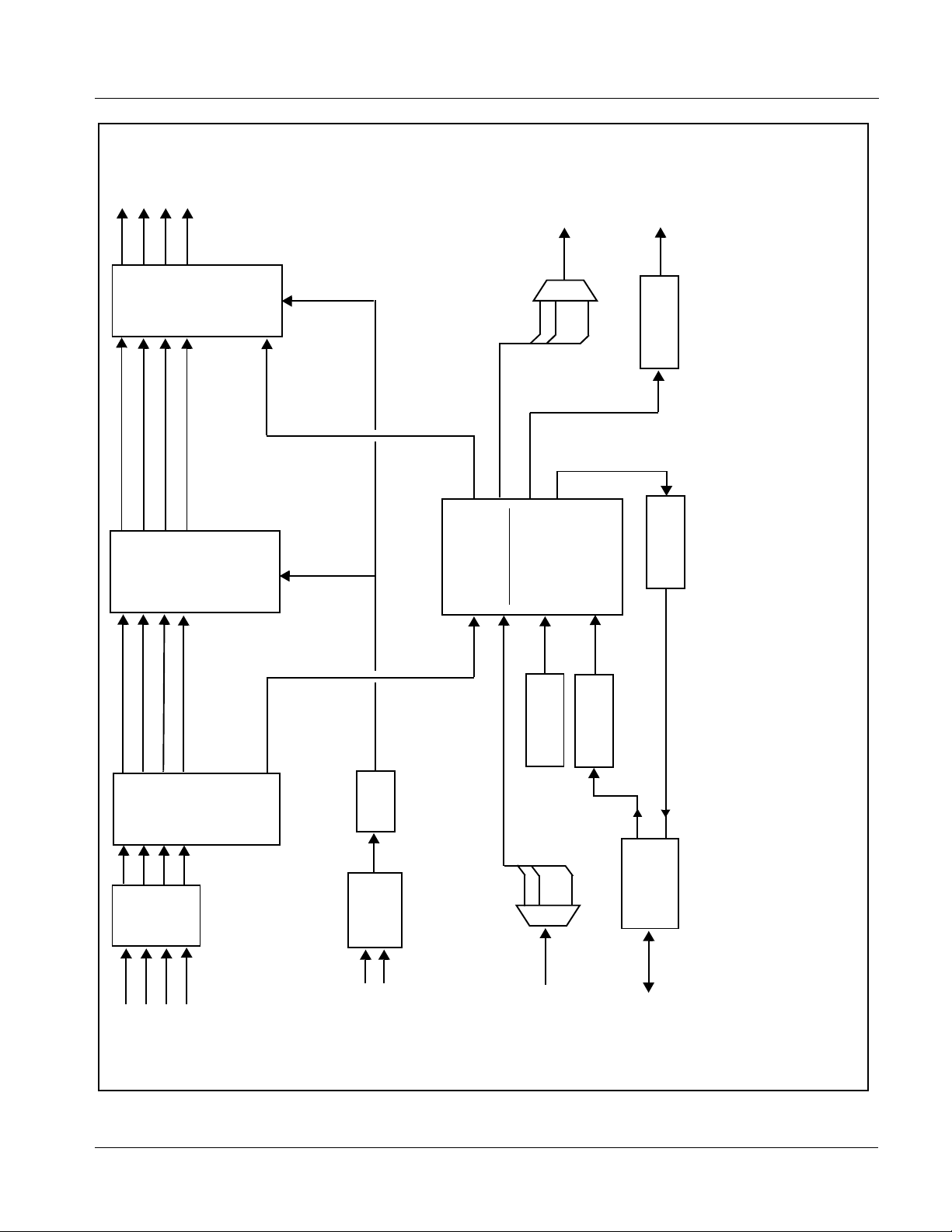
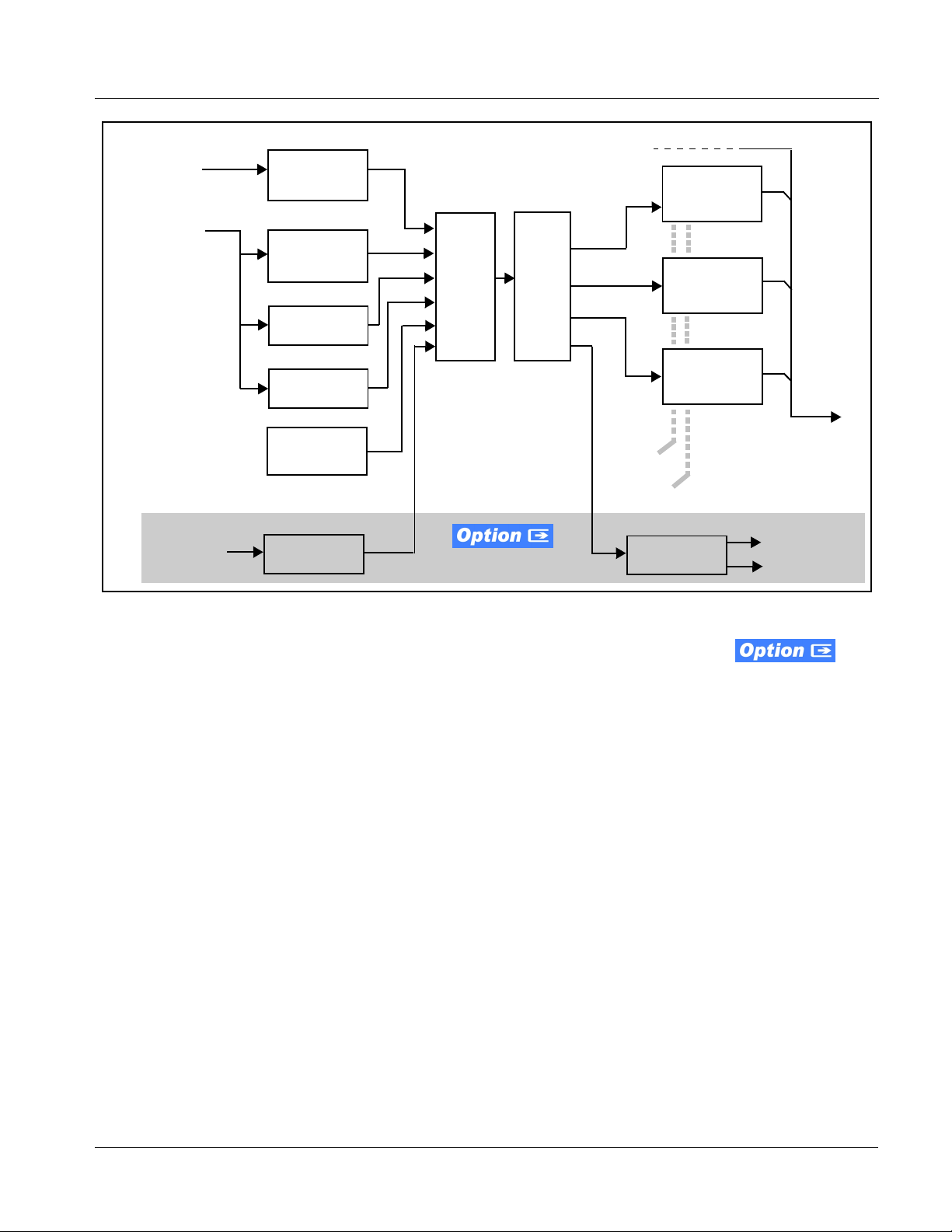
Introduction 9374-Series Cards Functional Description
9374-Series Cards Functional Description
Figure 1-1 shows a functional block diagrams of the 9374-Series card.
9374-Series Input/Output Formats
The 9374, 9372, and 9371 cards whi ch compri se the 937 4-S eries vary onl y in
the number of discrete SDI streams (channels) handled by the card. Each
embedded channel within an SDI stream can be swapped between SDI
streams or between the card’s AES and MADI interfaces as shown for each
card in Table 1-1. Furthermore each of these three cards is available as
embedder-only (- EM) or de-embedd er- only (-DE) ver sions. Where f unctional
or operating descriptions apply only to specific cards, these differences are
noted.
Table 1-1 9374-Series Input/Output Overview
Analog Audio
Out (2-Ch
Card Model SDI Streams AES In AES Out MADI In MADI Out
Monitor)
1
1
1
8 pair max
8 pair max
8 pair max
9374-EMDE (4) 3G/HD/SD 8 pair max
9374-EM (4) 3G/HD/SD 8 pair IN 1 BNC
9374-DE (4) 3G /HD /SD 8 pair OUT 1 BNC
9372-EMDE (2) 3G/HD/SD 8 pair max
9372-EM (2) 3G/HD/SD 8 pair IN 1 BNC
9372-DE (2) 3G /HD /SD 8 pair OUT 1 BNC
9371-EMDE (1) 3G/HD/SD 8 pair max
9371-EM (1) 3G/HD/SD 8 pair IN 1 BNC
9371-DE (1) 3G /HD /SD 8 pair OUT 1 BNC
(1) On -EMDE, 8 AES pairs (BNCs) total are available, which can be selected as either inputs or outputs
(2) Input/output complements listed require appropriate rear I/O module. See 9374-Series Card Rear Modules (p. 2-4) in Chapter 2,
“Installation and Setup” for more information.
1
1 BNC 1 BNC
1
1 BNC 1 BNC
1
1 BNC 1 BNC
2-Ch
2-Ch
2-Ch
2-Ch
2-Ch
2-Ch
2-Ch
2-Ch
2-Ch
Note: V ideo formats on SDI IN A / SDI IN B must be same format. First received input
sets priority. If next received input is not of this format, its output is replaced
with a flat-field of the priority format and an alarm is set. SDI input pairs on
IN C
/ SDI IN D have similar constraints. Note however that common formats
are not required between input pair
SDI IN A / SDI IN B and SDI IN C / SDI IN D.
SDI
937X- OM (V1.3) 9374-SERIES PRODUCT MANUAL 1-5
Page 10

1 9374-Series Cards Functional Description
Audio Crosspoint/Processing Description
Note: Descriptions below are specific to the 9374-EMDE quad stream model. Other
models function identically but have less channel capacity and/or
embed/de-embed as described in Table 1-1.
(See Figure 1-1.) The 9374-Series provides a full unrestricted audio
crosspoint that allows channel routing between any channels on up to four
SDI streams, discrete AES-3id, and AES-10 MADI interfaces. The MADI
interface on the 9374-Series cards support a 64-channel payload at the
industry standard 48 kHz sampling rate, and can reliably recei ve from 1694A
cable runs up to 250m. All SDI embedding and SDI ou tput timing is timed in
common to a selected timing source. Discrete AES-3id inputs which are
asynchronous with input video are accommodated using per-channel Sample
Rate Converters (SRCs).
The 9374-Series audio crosspoint is built around a card internal bus that can
receive from the following inputs:
• 16 channels of de-embedded audio from each SDI program video
stream
• Up to 16 channels (8 pairs) of discrete AES input
• Up to 64 channels of MADI input audio on the MADI input BNC
• Digital silence (mute) setting
• 16 built-in independent tone generators
• (option +LTC only) LTC encoder LTCA thru LTCD
Any of the inputs de scrib ed above can be cross -rout ed to a ny of t he fol lowing
output destinations:
• 16 channels of embedded audio onto any of the card SDI output
streams
• Up to 16 channels (8 pairs) of discrete AES output
• Up to 64 channels of MADI output audio on the MADI output BNC
Note: Maximum AES-3id capacity is 8 pairs, of which each pair can be user
GUI-selectable as an input or output.
For each of the inputs and outputs described above, a PPM VU meter
representation on the GUI is provided. For each input channel pair is a
selectable instant routing that places the channel pair on the card’s analog
output pair, thereby conveniently providing a confidence monitor for each
channel pair. This stereo analog pai r can in tu rn be ro uted t o an e xtern al audio
monitor or powered monitors (the analog output pair is a consumer-level
unbalanced stereo pair.)
Output audio rates are always 48 kHz using timing alignment as selected by
user controls to frame
REF 1 or a selected SDI input stream.
1-6 9374-SERIES PRODUCT MANUAL 937X-OM (V1.3)
Page 11
Introduction 9374-Series Cards Functional Description
SDI OUT A
SDI OUT B
SDI OUT C
SDI OUT D
(NOTE 5)
MADI AUDIO
OUT (BNC)
Audio
Embed
1-16 Embed A
1-16 Embed B
1-16 Embed C
1-16 Embed D
•••
MADI Mux
(1-64)
DAC
24-Bit
Flat-Field
Audio
EQ/
/Insertion
Generators
De-Embed
Reclock
AES
Controls
Control
Audio Crosspoint
with Level/Monitor
1-16 De-embed A
1-16 De-embed B
1-16 De-embed C
1-16 De-embed D
Input/Output
PPM GUI Meters
Tone
AES
Generators
Receiver/SRC
Transmitter
Notes: 1. Signal connections shown depicts full input/output capability. Practical input/output signal availability is determined by Rear
I/O Module used. Refer to 9374-Series Card Rear Modules (p. 2-4) for more information.
9374: Four SDI channels (A thru D)
9372: Two SDI channels (A and B)
9371: One SDI channel (A)
Direction Control block and have either eight AES BNC inputs or outputs, and one MADI input or output, as applicable.
2. SDI channels accommodated depends on model:
3. -EM and -DE models are AES/MADI embedding and de-embedding only, respectively. T hese models do not use AES Port
outputs which are outputted via a 1x4 DA linked to the single processed card channel.
4. REF 1 is reference signal distributed on frame.
5. 9372 has four SDI ou tput s w hic h ar e o utp utte d vi a a 2x4 DA li nked to th e two pr oce ssed ca rd c ha nnel s. 937 1 ha s fo ur S DI
PLL
•••
(1-64)
Select
Timing
Reference
Control
AES Port
Direction
MADI De-mux
REF 1
SDI IN D
INPUT VIDEO
(from any SDI
input A thru D)
MADI AUDIO
SDI IN A
IN (BNC)
SDI IN B
SDI IN C
(8 BNC)
AES IN/OUT
937X BDV1.0 LB63
Figure 1-1 9374-Series Functional Block Diagram
937X- OM (V1.3) 9374-SERIES PRODUCT MANUAL 1-7
Page 12

1 9374-Series Cards Functional Description
Reference Function
The 9374-series cards use a common reference for all SDI video channels,
with the reference being selectable from
obtained from the frame references. This provides for proper audio
embedding, and rendering and switchover transiti ons from program video to
the flat-field generators as well as stable ou tput video .
Note: Where multiple SDI streams are to accommodated by the card, certain con-
siderations exist regarding video formats handled simultaneously. See Considerations Regarding Multiple-Channel SDI (p. 3-8) in Chapter 3, Operating
Instructions for more information. Unless all SDI inputs received by the card
are synchronous, all SDI inputs should be frame-synchronized using a common frame reference, with the same reference also to be used by this card.
MADI sources should also be frame-referenced to either the video being used
or a reference. Asynchronous AES audio is sample-rate converted to accommodate minor timing variances. Received SMPTE 337 (Dolby
AES input is automatically bypassed from the sample rate converters; this
data must be synchronous to video.
Flat-Field Generators
SDI A IN thru SDI D IN, or REF 1
®
data) over an
Independent flat-field generators are provided for each SDI channel. Either
manually selected or via failover on loss of SDI input, the generators are
individually configurable to output a flat field, with nine choices of color
being user selectable.
Tone Generators
The 9374-Series contains 16 built-in tone generators of frequencies from
20 Hz to 20 kHz (default level is -20 dBFS). (Where card is licensed for
+LTC,
only 12 tone generators are present.)
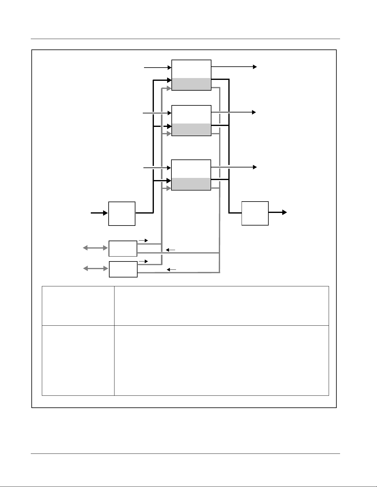
Timecode Processor
(See Figure 1-2.) This function uses extracted ti mecode data from the input
video (waveform or ATC), reference VITC waveform, or internal (free run)
and in turn re-inserts selected timecode data into the program video signal.
Each channel supported by the card has its own independent processor. The
function can monitor video input and reference input for supported timecode
formats, and then select and prioritize among SDI VITC waveform, SDI
ATC_VITC, and SDI ATC_LTC timecode sourc es. If the preferred format is
detected, the preferr ed format is used by the c ard; if the pr eferred for mat is
not detected, the card uses other formats (where available) as desired.
The function also provi des conv ersio n bet ween var ious t imecode format s and
provides independent insertion and line number controls for each SDI
timecode output format.
1-8 9374-SERIES PRODUCT MANUAL 937X-OM (V1.3)
Page 13
Introduction 9374-Series Cards Functional Description
Frame
Reference
Program
Video
Input
Audio/
RS-485 LTC
Ref VITC
Waveform
Detect/Extract
SDI VITC
Waveform
Detect/Extract
SDI ATC_VITC
Detect/Extract
SDI ATC_LTC
Detect/Extract
Free Run
(Internal Count)
Audio LTC
Select/Extract
Priority/
Select
Buffer/
Format
Output Video
Insert
Control
Line
Number
Control
Audio/RS-485
LTC Generate
SDI VITC
Timecode
Proc/Embed
ATC_VITC
Timecode
Proc/Embed
ATC_LTC
Timecode
Proc/Embed
Audio LTC Out
RS-485 LTC Out
Figure 1-2 Timecode Processor (One Channel Shown)
Audio/RS-485 LTC Function (Option +LTC)
Note: +LTC function is an optional licensable feature. This function and its controls
appear only when a license key is entered and activated. (This option (identified in Cobalt
field-activated using a key string which is sent to you when this option is purchased.)
(See Figure 1-3.) Option +LTC allows bidirectional transfer and conversion
between SMPTE 12M VANC formats over SDI and audio LTC, as well as
RS-485 LTC. Audio LTC can be received or sent over digital audio using
selected embedded or AES channel, as well as via two RS-485 ports on the
card.
RS-485/Audio LTC can be derived from each card SDI channel VANC
timecode.
®
price lists as +LTC) can be purchased upon initial order, or
937X- OM (V1.3) 9374-SERIES PRODUCT MANUAL 1-9
Page 14
1 9374-Series Cards Functional Description
Audio LTC FROM
AES or MADI
SDI IN A
SDI IN B
SDI IN D
AES/MADI
LTC IN
Channel
Select
SDI VANC
Timecode
Select/Extract
Audio LTC
Insert/Extract
SDI VANC
Timecode
Select/Extract
Audio LTC
Insert/Extract
•
•
•
SDI VANC
Timecode
Select/Extract
Audio LTC
Insert/Extract
SDI OUT A
SDI OUT B
SDI OUT D
AES/MADI
LTC OUT
Channel
Select
Audio LTC TO
AES or MADI
COM 1 RS-485
LTC I/0
COM 2 RS-485
LTC I/0
I/O Control
I/O Control
LTC Input (Rx) Sources Each SDI channel can select sources for its respective LTCA thru LTCD encoders from the
following:
- Audio LTC from Chan A thru D Emb 1-16 input, AES 1-16, MADI 1-64.
- RS-485 LTC from COM1 or COM2.
- Timecode source priority selection from reference VITC, VITC waveform, ATC_VITC,
ATC_LTC, or free-run timecode as source.
LTC Output (Tx)
Destinations
Each respective LTCA thru LTCD encoder is independently related to each SDI input channel,
and can output LTCA thru LTCD independently (as source choices LTCA thru LTCD) to the
following destinations:
- SDI Chan A thru D VANC (as VITC waveform, ATC_VITC, or ATC_LTC as applicable for
video format).
- Output audio LTC over SDI Chan A thru D Emb 1-16 output.
- Audio LTC to AES 1-16, MADI 1-64
- RS-485 COM1 or COM2.
LTCA thru LTCD can be used as sources for any audio channel or SDI output channel.
(9372 card has only LTCA and LTCB encoders; 9371 card has only LTCA encoder.)
Figure 1-3 Timecode Interfaces Using Option +LTC
1-10 9374-SERIES PRODUCT MANUAL 937X-OM (V1.3)
Page 15
Introduction 9374-Series Cards Functional Description
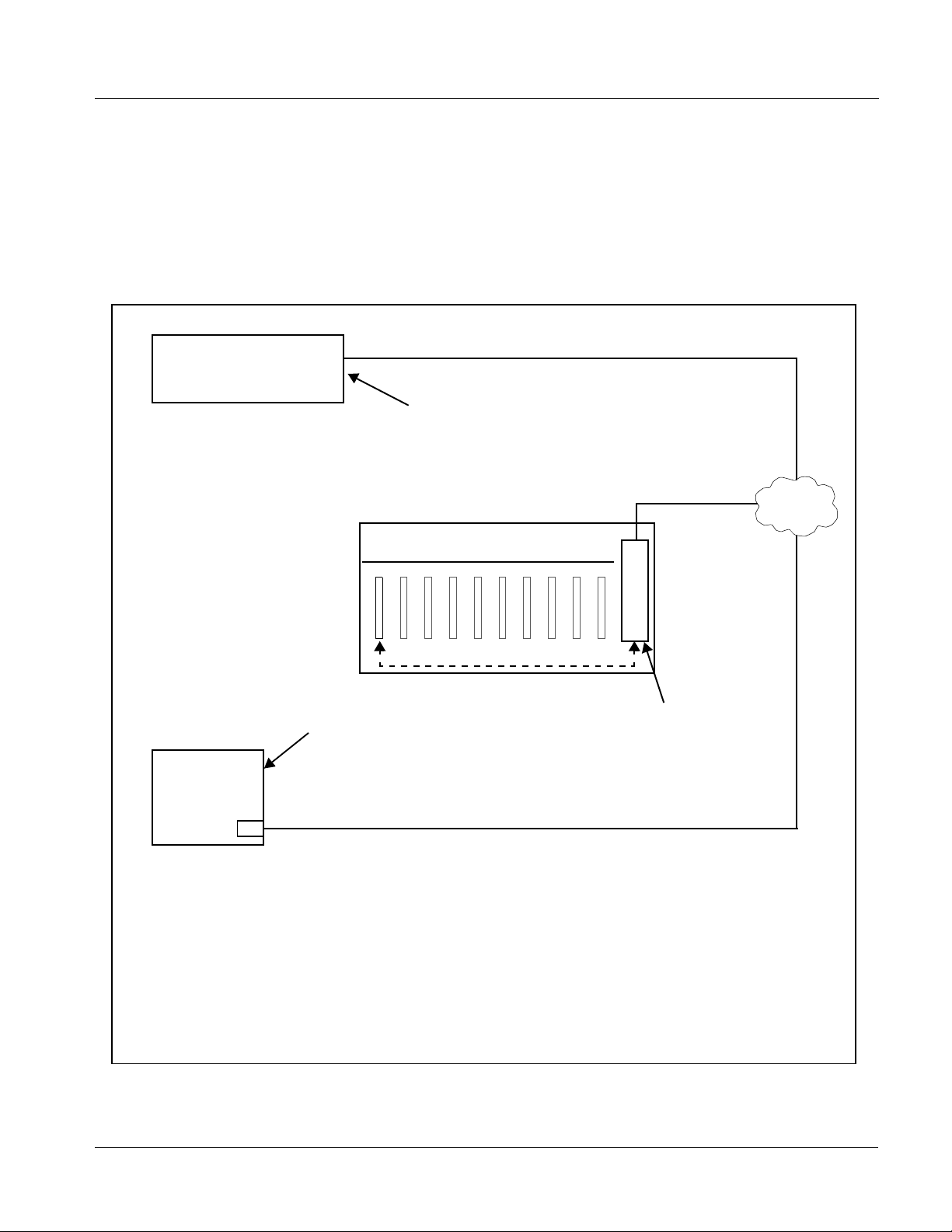
User Control Interface
Figure 1-4 shows the user cont rol inte rface op tions for the 9374-Serie s. These
interfaces are individually described below.
Note: All user control interfaces described here are cross-compatible and can oper-
ate together as desired. Where applicable, any control setting change made
using a particular user interface is reflected on any other connected interface.
OGCP-9000 Control Panel
OGCP-9000/CC Control Panel
Computer
with NIC
or
DashBoard™ Remote Control
Using a computer with
DashBoard™ installed,
9374-Series card can be
remotely controlled over a LAN
Remote Control Panel
Using the Control Panel,
9374-Series card can be
remotely controlled over a LAN
LAN
20-Slot Frame with MFC-8320-N network
controller card
In conjunction with a frame equipped
with an MFC-8320-N network
controller card, 9374-Series card can
be remotely controlled over a LAN
Note: • To communicate with DashBoard™ or a Remote Control Panel, the frame must have the optional
MFC-8320-N network controller card installed.
• DashBoard™ and the Remote Control Panels provide network control of the 9374-Series as
shown. The value displayed at any time on the card, or via DashBoard™ or a Control Panel is the
actual value as set on the card, with the current value displayed being the actual value as effected
by the card. Parameter changes made by any of these means are universally accepted by the
card (for example, a change made using DashBoard™ controls will change the setting displayed
on both DashBoard™ and a Control Panel; a change made using a Control Panel will similarly
change the setting displayed on the Control Panel and DashBoard™).
Figure 1-4 9374-Series User Control Interface
937X- OM (V1.3) 9374-SERIES PRODUCT MANUAL 1-11
Page 16

1 9374-Series Cards Functional Description
• DashBoard™ User Interface – Using DashBoard
and other cards installed in openGear
®
frames such as the Cobalt®
1
, the 9374-Series
HPF-9000 or 8321 Frame can be controlled from a computer and
monitor. DashBoard™ allows users to view all frames on a network
with control and monitori ng for all populated slots inside a frame.
This simplifies the setup and use of numerous modules in a large
installation and offers the ability to centralize monitoring. Cards
define their controllable parameters to DashBoard™, so the control
interface is always up to date. The DashBoard™ software can be
downloaded from the Cobalt Digital Inc. website:
www.cobaltdigital.com
(enter “DashBoard” in the search window).
The DashBoard™ user inter face is describe d in Chapter 3,“Operating
Instructions”.
Note: If network remote control is to be used for the frame and the frame has not yet
been set up for remote control, Cobalt
User Guide (PN 9000RCS-RM) provides thorough information and
step-by-step instructions for setting up network remote control of COMPASS
and FUSION3G
OGCP-9000/CC Remote Control Panel product manuals have complete
instructions for setting up remote control using a Remote Control Panel.)
Download a copy of this guide by clicking on the Support>Documents>
Reference Guides link at www.cobaltdigital.com and then select DashBoard
Remote Control Setup Guide as a download, or contact Cobalt
Contact Cobalt Digital Inc. (p. 1-18).
®
cards using DashBoard™. (Cobalt® OGCP-9000 and
®
reference guide Remote Control
®
as listed in
®
Note: Some GUI features such as VU meters are not available when using the
Remote Control Panel user interface.
9374-Series Card Rear Modules
The 9374-Series cards physically interface to system video and audio
connections using a Rear Module.
All inputs and o utp uts shown in the block diagram (Figure 1-1) enter and exit
the card via the card edge backplane connector. The Rear Module breaks out
the 9374-Series card edge connections to industry standard connections that
interface with other components and systems in the signal chain.
• Cobalt
®
OGCP-9000, OGCP-9000/CC and WinOGCP Remote
Control Panels – The OGCP-9000, OGCP-9000/CC, and WinOGCP
Remote Control Panels conveniently and intui ti vel y provi de
parameter monitor and c ontrol of the cards within the 20-slot f rame.
The Control Panels allow quick and intuitive access to hundreds of
cards in a facility, and can monitor and allow adjustment of multiple
parameters at one time. The Remote Control P anels are to tally
compatible with the op enGear
®
control software DashBoard™; any
changes made with either system are reflected on the other.
1. openGear® is a registered trademark of Ross Video Limited. DashBoard™ is a trademark of Ross
Video Limited.
1-12 9374-SERIES PRODUCT MANUAL 937X-OM (V1.3)
Page 17

Introduction 9374-Series Cards Functional Description
In this manner, the particular inputs and outputs required for a particular
application can be accommodated using a Rear Module that best suits the
requirements. The required input and outputs are broken out to the industry
standard connectors on the Rear Module; the unused inputs and outputs
remain unterminated and not available for use.
The full assortment of 9374-Series Rear Modules is shown and described in
9374-Series Card Rear Modules (p. 2-4) in Chapter 2, “Installation and
Setup”.
Audio and Video Formats Supported by the 9374-Series Cards
Table 1-2 lists and provides details regarding the audio and video formats
supported by the 9374-Series cards.
Table 1-2 Supported Audio and Video Formats
Item Description/Specification
Input / Output Video Raster Structure: Frame Rate:
1080p 23.98; 24 29.97; 25; 30
(1)
(2)
50, 59.94, 60
25; 29.97; 30
1080p 3G
1080i
720p 23.98; 24; 25; 29.97; 30; 50;
59.94; 60
(1)
486i
575i
(1)
29.97
25
Embedded Audio The 9374-Series cards support all four groups (16 channels) of
embedded audio at full 24-bit resolution in both SD (with extended data
packets) and HD for each of the card’s SDI streams.
Discrete AES Audio (AES-3id) The 9374-Series cards can accept 16 channels (8 pairs) of discrete
AES audio on 75Ω BNC connections (maximum total of inputs and
outputs). Sample rate conversion is employed to accommodate sample
rate differences in the AES stream and the input video stream.
AES-3id outputs can be sourced from any SDI embedded channel,
MADI input, or other AES-3id inputs received by the card.
MADI Audio (AES-10) The 9374-Series cards have a 75Ω BNC input and output connection
that supports the MADI standard of up to 64 channels input and output.
MADI outputs can be sourced from any SDI embedded channel,
AES-3id inputs, or other MADI channels received by the card.
(1) All rates displayed as frame rates; interlaced (“i”) field rates are two times the rate value shown.
(2) All inputs must be synchronous (e.g., all frame synced to same reference) to assure clean audio cross-routing between SDI
streams. Multiple simultaneous formats are supported on a limited basis (e.g., HD on SDI Inputs A/B and SD on SDI Inputs C/D).
AES-3id and MADI should also be synchronous with selected SDI stream(s) to ensure clean audio cross-routing.
937X- OM (V1.3) 9374-SERIES PRODUCT MANUAL 1-13
Page 18

1 Technical Specifications
Technical Specifications
Table 1-3 lists the technical specifications for the 9374-Series of
SDI-AES-MADI Embedder/De-embedders.
Note: Input/output types and number of input/outputs in some cases are a function
of rear module installed. Refer to Table 1-1, “9374-Series Input/Output Overview” for detailed information on available input/output complements.
Table 1-3 Technical Specifications
Item Characteristic
Part number, nomenclature 9374-EMDE Quad-Stream SDI-AES-MADI Embedder/De-embedder
9374-EM Quad-Stream SDI-AES-MADI Embedder
9374-DE Quad-Stream SDI-AES-MADI De-embedder
9372-EMDE Dual-Stream SDI-AES-MADI Embedder/De-embedder
9372-EM Dual-Stream SDI-AES-MADI Embedder
9372-DE Dual-Stream SDI-AES-MADI De-embedder
9371-EMDE SDI-AES-MADI Embedder/De-embedder
9371-EM SDI-AES-MADI Embedder
9371-DE SDI-AES-MADI De-embedder
Note: See Table 1-1 on pag e 1-5 for input/output capabilities for
specific models.
Installation/usage environment Intended for installation and usage in frame meeting openGear
Power consumption < 20 Watts maximum (all options installed)
Environmental:
Operating temperature:
Relative humidity (operating or storage):
Frame communication 10/100 Mbps Ethernet with Auto-MDIX.
Internal Tone Generators 16 built-in tone generators, each configurable for frequencies ranging
Standards Supported 3G: SMPTE 425 level A and B
Internally generated flat -fie ld form at s
Note: Flat-field format is user-selectable using GUI
controls and independent of received (input video)
format.
modular system definition.
32° – 104° F (0° – 40° C)
< 95%, non-condensing
from 20 Hz to 20 kHz (default level = -20 dBFS).
(Where card is licensed for +LTC, only 12 tone generators are
present.)
1080p60, 1080p59.94, 1080p50
HD: 1080i60, 1080i59.94, 1080i50, 1080p29.97, 1080p25, 1080p24;
1080p23.98
720p60, 720p59.94, 720p50, 720p29.97, 720p25, 720p24,
720p23.98
SD: 486i59094, 576i50
3G: 1080p59.94, 1080p50
HD: 1080i59.94, 1080i50, 1080psf23.98
720p59.94, 720p50
SD: 525i59.94, 625i50
®
1-14 9374-SERIES PRODUCT MANUAL 937X-OM (V1.3)
Page 19

Introduction Technical Specifications
Table 1-3 Technical Specifications — continued
Item Characteristic
BNC SDI Video Inputs/Outputs Data Rates Supported:
SMPTE 425 level A and B: 3 Gbps
SMPTE 292 HD-SDI: 1.485 Gbps or 1.485/1.001 Gbps
SMPTE 259M-C SD-SDI: 270 Mbps
BNC Connector Input/Output Impedance:
75 Ω terminating
Cable Equal ization (3G) :
394 ft (120 m) Belden 1694A
Cable Equalization (HD):
591 ft (180 m) Belden 1694A
Cable Equalization (SD):
1050 ft (320 m) Belden 1694A
Return Loss:
> 15 dB up to 1.485 GHz
> 10 dB up to 2.970 GHz
Jitter; Alignment (3G / HD / SD):
< 0.3 UI / 0.2 UI / 0.2 UI
Jitter; Timing (3G / HD / SD):
< 2.0 UI / 1.0 UI / 0.2 UI
AES (AES-3id) Audio Inputs/Outputs Standard:
SMPTE 276M
Number of inputs/ou t puts (maximum total between inputs and outp ut s ) :
8 pairs (16-channel) on BNC connectors per AES-3id; 75 Ω
impedance
Input Level:
0.2 to 2.0 Vp-p
Output Level:
1.0 Vp-p
Return Loss:
> 15 dB @ up to 6.144 MHz
Input SRC Range:
32 kHz to 96 kHz
Input SRC Performance:
>130 dB THD+N
MADI (AES-10) Inputs/Outputs Number of Inputs/Outputs:
1 BNC Input, 1 BNC Output
Supported Sample Rate:
48 kHz only
Input/Output Impedance:
75 Ω
Input Data Rates:
125 Mbps
Input Level:
0.15 - 0.6 Vp-p
Output Level:
0.3 - 0.6 Vp-p
Output Jitter:
0.1 UI
937X- OM (V1.3) 9374-SERIES PRODUCT MANUAL 1-15
Page 20

1 Technical Specifications
Table 1-3 Technical Specifications — continued
Item Characteristic
Analog Audio Outputs Two unbalanced “RCA”; consumer-level confidence monitor (2 V r ms
Audio/Video Delay Less than 30 audio samples (embed or de-embed)
Frame Reference Input Number of Inputs:
(+6 dBV) for 0 dBFS PCM signal)
One non-terminating (looping) Frame Reference input (REF 1)
Standards Supported:
SMPTE 170M/318M (“black burst”)
SMPTE 274M/296M (“tri-color”)
Return Loss:
> 35 dB up to 5.75 MHz
1-16 9374-SERIES PRODUCT MANUAL 937X-OM (V1.3)
Page 21

Introduction Warranty and Service Information
Warranty and Service Information
Cobalt Digital Inc. Limited Warranty
This product is warranted to be free from defects in material and workmanship for a period of five (5)
years from the date of shipment to the original purchaser, except that 4000, 5000, 6000, 8000 series
power supplies, and Dolby
material and workmanship for a period of one (1) year.
Cobalt Digital Inc.'s (“Cobalt”) sole obligation under this warranty sh all be limited to, at its option, (i)
the repair or (ii) replacement of the produc t, and the det ermination of whether a defect is covered under
this limited warranty shall be made at the sole discretion of Cobalt.
This limited warrant y appl ies on ly t o the origi nal end-pu rchaser of the produ ct, and i s not assign able o r
transferrable therefrom. This warr ant y i s li mited to defects in material and workmanship, and shall not
apply to acts of God, accidents, or negligence on behalf of the purchaser, and shall be voided upon the
misuse, abuse, alteration, or modification of the product. Only Cobalt authorized factory
representatives are authorized to make repairs to the product, and any unauthorized attempt to repair
this product shall immediately void the warranty. Please contact Cobalt Technical Support for more
information.
®
modules (where applicable) are warranted to be free from defects in
To facilitate the resolut ion of warranty related issues, Cobalt recommends registering the product by
completing and returning a product registration form. In the event of a warrantable defect, the
purchaser shall notify Cobalt with a descripti on of the problem, and Cobalt shall provide the purchaser
with a Re turn Mate rial Auth oriz ation (“RMA”). For retu rn, defective product s should be double boxed,
and sufficiently protecte d, in the original packa ging, or equivalent, a nd shipped to the Coba lt Factory
Service Center, postage prepaid and insured for the purchase price. The purchaser should include the
RMA number, description of the problem encountered, date purchased, name of dealer purchased
from, and serial number with the shipment.
Cobalt Digital Inc. Factory Service Center
2406 E. University Avenue Office: (217) 344-1243
Urbana, IL 61802 USA Fax: (217) 344-1245
www.cobaltdigital.com Email: info@cobaltdigital.com
THIS LIMITED WARRANTY IS EXPRESSLY IN LIEU OF ALL OTHER WARRANTIES
EXPRESSED OR IMPLIED, INCLUDING THE WARRANTIES OF MERCHANTABIL ITY AND
FITNESS FOR A PARTICULAR PURPOSE AND OF ALL OTHER OBLIGATIONS OR
LIABILITIES ON COBALT'S PART. ANY SOFTWARE PROVIDED WITH, OR FOR USE WITH,
THE PRODUCT IS PROVIDED “AS IS.” THE BUYER OF THE PRODUCT ACKNOWLEDGES
THAT NO OTHER REPRESENTATIONS WERE MADE OR RELIED UPON WITH RESPECT TO
THE QUALITY AND FUNCTION OF THE GOODS HEREIN SOLD. COBALT PRODUCTS ARE
NOT AUTHORIZED FOR USE IN LIFE SUPPORT APPLICATIONS.
COBALT'S LIABILITY, WHETHER IN CONTRACT, TORT, WARRANTY, OR OTHERWISE, IS
LIMITED TO THE REPAIR OR REPLACEMENT, AT ITS OPTION, OF ANY DEFECTIVE
PRODUCT, AND SHALL IN NO EVENT INCLUDE SPECIAL, INDIRECT, INCIDENTAL, OR
CONSEQUENTIAL DAMAGES (INCLUDING LOST PROFITS), EVEN IF IT HAS BEEN
ADVISED OF THE POSSIBILITY OF SUCH DAMAGES.
937X- OM (V1.3) 9374-SERIES PRODUCT MANUAL 1-17
Page 22

1 Contact Cobalt Digital Inc.
Contact Cobalt Digital Inc.
Feel free to contact our thorough and professional support representative s for
any of the following:
• Name and address of your local dealer
• Product information and pricing
• Technical support
• Upcoming trade show information
Phone: (217) 344-1243
Fax: (217) 344-1245
Web: www.cobaltdigital.com
General Information: info@cobaltdigital.com
Technical Support: support@cobaltdigital.com
1-18 9374-SERIES PRODUCT MANUAL 937X-OM (V1.3)
Page 23
Overview
Chapter 2
Chapter 2 Installation and Setup
This chapter contains the following information:
• Installing the 9374-Series Card Into a Frame Slot (p. 2-1)
• Installing a Rear Module (p. 2-3)
• 9374-Series Analog Audio Output (p. 2-10)
• Setting Up 9374-Series Card Network Remote Control (p. 2-10)
Note: The 9374-Series cards are suitable for installation only in a 20-slot frame
(Cobalt
®
PN HPF-9000 or 8321-CN or equivalent).
Installing the 9374-Series Card Into a Frame Slot
CAUTION
Heat and power distribution requirements within a frame may dictate specific
slot placement of cards. Cards with many heat-producing compon ents should
be arranged to avoid areas of excess heat build-up, particularly in frames
using only convection cooling. The 9374-Series cards have a moderate power
dissipation (20 W max.). As such, avoiding placing the card adjacent to other
cards with similar dissipation values if possible.
CAUTION
This device contains semiconductor devices which are
susceptible to serious damage from Electrostatic
Discharge (ESD). ESD damage may not be immediately
apparent and can affect the long-term reliability of the
device.
Avoid handling circuit boards in high static environments
such as carpeted areas, and when wearing synthetic fiber
clothing. Always use proper ESD handling precautions
and equipment when working on circuit boards and
related equipment.
937X- OM (V1.3) 9374-SERIES PRODUCT MANUAL 2-1
Page 24

2 Installing the 9374-Series Card Into a Frame Slot
CAUTION
If required, make certain Rear Module(s) is installed before installing the card
into the frame slot. Damage to card and/or Rear Module can occur if module
installation is attempted with card already installed in slot.
Note: Check the packaging in which the 9374-Series Card was shipped for any
extra items such as a Rear Module connection label. In some cases, this label
is shipped with the card and to be installed on the Rear I/O connector bank
corresponding to the slot location of the card.
Install the 9374-Seri es Card into a frame slot as follows:
1. Determine the slot in which the 9374-Series Card is to be installed.
2. Open the frame front access panel.
3. While holding the card by the card edges, align the card such that the
plastic ejector tab is on the bottom.
4. Align the card with the top and bottom guides of the slot in which the
card is being installed.
5. Gradually slide the card into the slot. When resistance is noticed, g ently
continue pushing the card until its rear printed circuit edge terminals
engage fully into the Rear Module mating connector.
CAUTION
If card resists fully engaging in Rear Module mating connector, check for
alignment and proper insertion in slot tracks. Damage to card and/or Rear
Module may occur if improper card insertion is attempted.
Verify that the card is fully engaged in Rear Module mating connector.
6.
7. Close the frame front access panel.
8. Connect cabling in accordance with the appropriate diagram shown in
Table 2-1, “9374-Series Card Rear Modules” (p. 2-5).
9. Repeat steps 1 through 8 for other 9374-Series Cards.
Notes: • The 9374-Series Card BNC inputs are internally 75-ohm terminated. It is not
necessary to terminate unused BNC inputs or outputs.
• External frame sync reference signals are received by the card over a
reference bus on the card frame, and not on any card rear I/O module
connectors. The frame has a BNC connector labeled REF 1 which receives
the reference signal from an external source such as a house distribution.
• T o rem ove a ca rd, pres s do wn on the ej ec tor tab to u nseat the card from the
Rear Module mating connector. Evenly draw the card from its slot.
10. If network remote cont rol is to be used for the frame and the frame has
not yet been set up for remote control, perform setup in accordance with
Setting Up 9374-Series Card Network Remote Control (p. 2-10).
2-2 9374-SERIES PRODUCT MANUAL 937X-OM (V1.3)
Page 25

Installation and Setup Installing a Rear Module
Note: If installing a card in a frame already equipped for, and connected to
DashBoard™, no network setup is required for the card. The card will be discovered by DashBoard™ and be ready for use.
Installing a Rear Module
Notes: • This procedure is applicable only if a Rear Module is not currently
installed in the slot where the 9374-Series Card is to be installed.
• Note that some Rear Modules and labels have several ventilation holes. To
allow maximum ventilation, it is recommended to place the label fully over
connectors such that label is flush with rear module and holes are not
obscured. Also, when a card is not installed in a slot, it is recommended that
the supplied blank cover be used to preserve proper forced ventilation
flow-through.
The full assortment of 9374-Series Card Rear Modules is shown and
described in 9374-Series Card Rear Modules (p. 2-4). Install a Rear Module
as follows:
1. On the frame, determine the slot in which the 9374-Series Card is to be
installed.
2. In the mounting area corresponding to the slot location, install
Rear Module as shown in Figure 2-1.
937X- OM (V1.3) 9374-SERIES PRODUCT MANUAL 2-3
Page 26
2 Installing a Rear Module
Align and engage mounting tab on Rear
I/O Module with the module seating slot
1
on rear of frame chassis.
DSCN3483A.JPG
Hold top of Rear Module flush against
frame chassis and start the captive screw.
2
Lightly tighten captive screw.
DSCN3487A.JPG
9374-Series Card Rear Modules
Table 2-1 shows and describes the full assortment of Rear Modules
specifically for use with the 9374-Series cards.
Note: The Rear Modules shown here are standard production items. Other signal
combinations may be available as custom items. Consult Product Support
with requests. Also, please check our web site pages for this product; new
Rear Modules may be available that are not listed here.
Figure 2-1 Rear Module Installation
2-4 9374-SERIES PRODUCT MANUAL 937X-OM (V1.3)
Page 27

Installation and Setup Installing a Rear Module
Table 2-1 9374-Series Card Rear Modules
9374 Card Rear Module Description
RM20-9374-B Rear Module Provides the following connections:
• Four 3G/HD/SD-SDI video input BNCs
(
SDI IN A thru SDI IN D)
MADI IN and MADI OUT MADI AES-10 BNC input
•
and output connectors
• Four 3G/HD/SD-SDI video output BNCs
SDI OUT A thru SDI OUT D)
(
RM20-9374-E Rear Module Provides the following connections:
• Four 3G/HD/SD-SDI video input BNCs (
thru SDI IN D
)
• Ei ght AE S I/O BNC (A ES -3i d ) input/outputs
AES 1 thru AES 8; I/O choice for each connection is
(
software-configurable; 8 ports total)
•
MADI IN and MADI OUT MADI AES-10 BNC input
and output connectors
• Two analog unbalanced (“RCA”) audio monitor
outputs (
AN-AUD OUT L and AN-AUD OUT R)
• Four 3G/HD/SD-SDI video output BNCs
(SDI OUT A thru SDI OUT D
)
SDI IN A
937X- OM (V1.3) 9374-SERIES PRODUCT MANUAL 2-5
Page 28

2 Installing a Rear Module
Table 2-1 9374-Series Card Rear Modules — continued
9374 Card Rear Module Description
RM20-9374-F Rear Module Provides the following conne cti on s:
• Four 3G/HD/SD-SDI video input BNCs (
thru SDI IN D
)
• Eight AES I/O BNC (AES-3id) input/outputs
(
AES 1 thru AES 8; I/O choice for each connec tion is
software-configurable; 8 ports total)
MADI IN and MADI OUT MADI AES-10 BNC input
•
and output connectors
• Two analog unbalanced (“RCA”) audio monitor
outputs (
• Two RS-485 ports (
AN-AUD OUT L and AN-AUD OUT R)
COM 1 and COM 2); each
assignable as Input or Output-LTC Encoder A
thru Output-LTC Encoder D outputs
• Four 3G/HD/SD-SDI video output BNCs
(SDI OUT A thru SDI OUT D
)
Note: • COM ports functional only on card equipped
with option +LTC.
• Rear module available equipped with
High-Density BNC (HDBNC) or DIN1.0/2.3
connectors as:
RM20-9374-F-HDBNC or
RM20-9374-F-DIN, respectively.
SDI IN A
RM20-9372-B Rear Module Provides the following connections:
• Two 3G/HD/SD-SDI video input BNCs
(
SDI IN A and SDI IN B)
•
MADI IN and MADI OUT MADI AES-10 BNC input
and output connectors
• Four 3G/HD/SD-SDI video output BNCs
(2x
SDI OUT A and 2x SDI OUT B)
2-6 9374-SERIES PRODUCT MANUAL 937X-OM (V1.3)
Page 29
Installation and Setup Installing a Rear Module
Table 2-1 9374-Series Card Rear Modules — continued
9374 Card Rear Module Description
RM20-9372-E Rear Module Provides the following connections:
• Two 3G/HD/SD-SDI video input BNCs (
and SDI IN B
)
• Ei ght AE S I/O BNC (A ES -3i d ) input/outputs
(
AES 1 thru AES 8; I/O choice for each connection is
software-configurable; 8 ports total)
MADI IN and MADI OUT MADI AES-10 BNC input
•
and output connectors
• Two analog unbalanced (“RCA”) audio monitor
outputs (
AN-AUD OUT L and AN-AUD OUT R)
• Four 3G/HD/SD-SDI video output BNCs
SDI OUT A and 2x SDI OUT B)
(2x
SDI IN A
RM20-9372-F Rear Module Provides the following connections:
• Two 3G/HD/SD-SDI video input BNCs (
and SDI IN B
)
• Ei ght AE S I/O BNC (A ES -3i d ) input/outputs
AES 1 thru AES 8; I/O choice for each connection is
(
software-configurable; 8 ports total)
•
MADI IN and MADI OUT MADI AES-10 BNC input
and output connectors
• Two analog unbalanced (“RCA”) audio monitor
outputs (
AN-AUD OUT L and AN-AUD OUT R)
• Two RS-485 ports (COM 1 and COM 2); each
assignable as Input or Output-LTC Encoder A
thru Output-LTC Encoder D outputs
• Four 3G/HD/SD-SDI video output BNCs
(2x
SDI OUT A and 2x SDI OUT B)
Note: • COM ports functional only on card equipped
with option +LTC.
• Rear module available equipped with
High-Density BNC (HDBNC) or DIN1.0/2.3
connectors as:
RM20-9372-F-HDBNC or
RM20-9372-F-DIN, respectively.
SDI IN A
937X- OM (V1.3) 9374-SERIES PRODUCT MANUAL 2-7
Page 30
2 Installing a Rear Module
Table 2-1 9374-Series Card Rear Modules — continued
9374 Card Rear Module Description
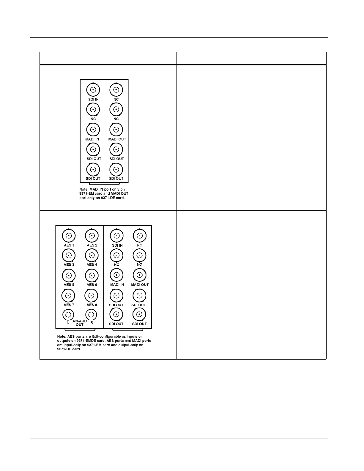
RM20-9371-B Rear Module Provides the following connections:
• 3G/HD/SD-SDI video input BNC (
•
MADI IN and MADI OUT MADI AES-10 BNC input
and output connectors
• Four 3G/HD/SD-SDI video output BNCs
(4x
SDI OUT A)
SDI IN)
RM20-9371-E Rear Module Provides the following conne cti on s:
• 3G/HD/SD-SDI video input BNC (
• Eight AES I/O BNC (AES-3id) input/outputs
(
AES 1 thru AES 8; I/O choice for each connec tion is
software-configurable; 8 ports total)
•
MADI IN and MADI OUT MADI AES-10 BNC input
and output connectors
• Two analog unbalanced (“RCA”) audio monitor
outputs (
AN-AUD OUT L and AN-AUD OUT R)
• Four 3G/HD/SD-SDI video output BNCs
(4x
SDI OUT A)
SDI IN)
2-8 9374-SERIES PRODUCT MANUAL 937X-OM (V1.3)
Page 31
Installation and Setup Installing a Rear Module
Table 2-1 9374-Series Card Rear Modules — continued
9374 Card Rear Module Description
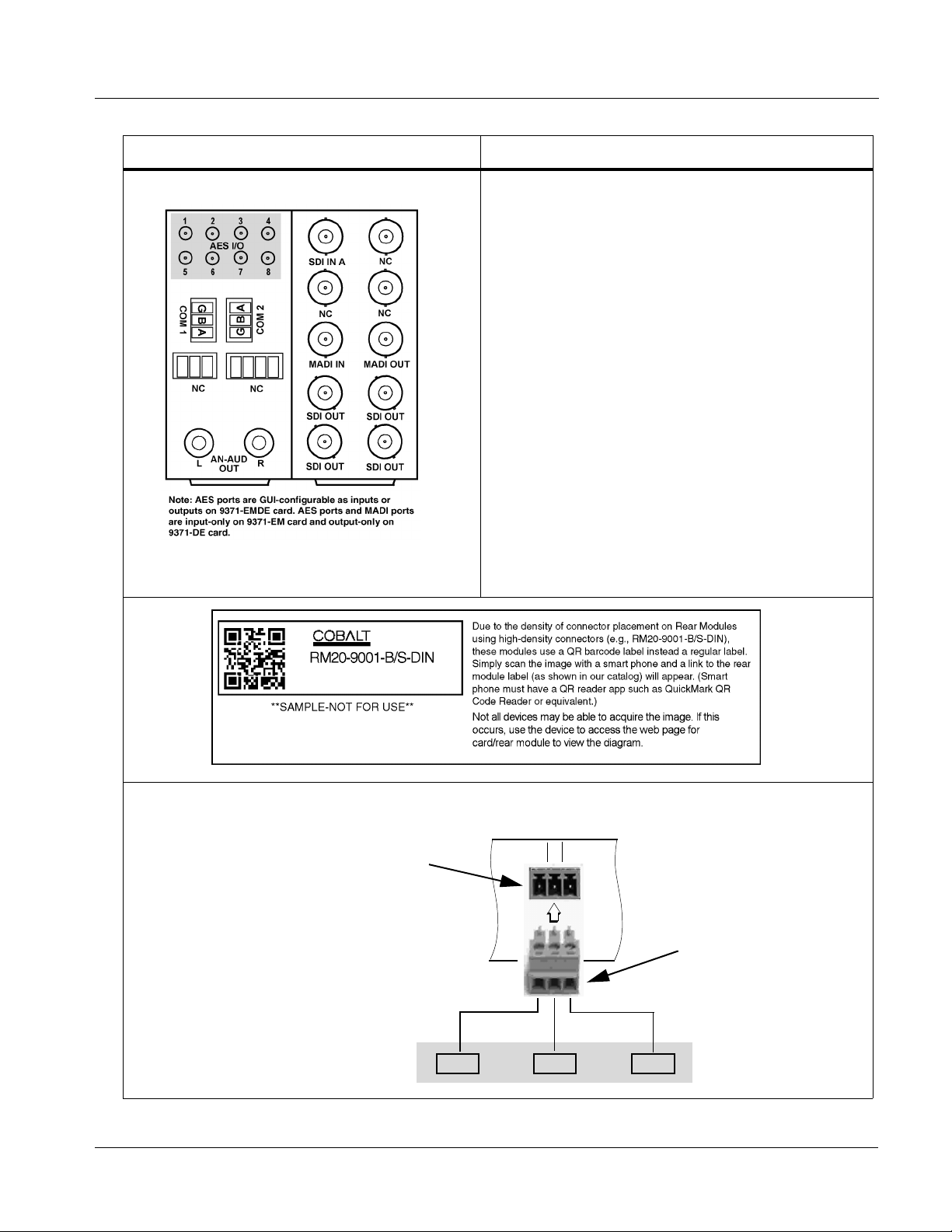
RM20-9371-F Rear Module Provides the following connections:
• 3G/HD/SD-SDI video input BNCs (
• Ei ght AE S I/O BNC (A ES -3i d ) input/outputs
(
AES 1 thru AES 8; I/O choice for each connection is
software-configurable; 8 ports total)
•
MADI IN and MADI OUT MADI AES-10 BNC input
and output connectors
• Two analog unbalanced (“RCA”) audio monitor
outputs (
• Two RS-485 ports (
AN-AUD OUT L and AN-AUD OUT R)
COM 1 and COM 2); each
assignable as Input or Output-LTC Encoder A
thru Output-LTC Encoder D outputs
• Four 3G/HD/SD-SDI video output BNCs
(4x
SDI OUT A)
Note: • COM ports functional only on card equipped
with option +LTC.
• Rear module available equipped with
High-Density BNC (HDBNC) or DIN1.0/2.3
connectors as:
RM20-9371-F-HDBNC or
RM20-9371-F-DIN, respectively.
SDI IN A)
RS-485 Connections to Removable Phoenix Connector
Rear module
PCB connector
A (-) B (+) G
937X- OM (V1.3) 9374-SERIES PRODUCT MANUAL 2-9
21C
Removable Phoenix plug
view oriented with top
(screw terminals) up
Page 32

2 9374-Series Analog Audio Output
9374-Series Analog Audio Output
The unbalanced “RCA” audio outputs on this card correspond to 2.2Vrms
output when sourced from a unity-gain 0dBFS digital sine-wave source.
Consumer audio is specified in dBV with a nominal (or recording) level of
-10dBV. The 2vrms maximum output level corresponds to +6dBV. The
unbalanced analog outp uts on this card a llow for 16dB of headroom abo ve the
nominal -10dBV consumer level (“headroom” is the range between the
maximum and nominal audio levels).
Professional balanced analog audio levels in the US typically use a +4dBu
nominal level with 20dB of headroom (-20dBFS). The maximum level for
balanced analog interf aces is +24dBu.
The headroom difference between consumer and professional audio will
result in a lower RCA consumer level when converting from professional
balanced analog a udi o. Fo r example, if pro level analog audio i s r ec eived and
transmitted via AES or embedded SDI to a receiver converting to RCA
analog audio, the output will be 4dB lower, with a nominal level of -14dBV.
The analog audio outputs on this card are designed as a monitor convenience
output, and are suitable for direct application with rack-mounted monitors or
powered monitor loudsp eake rs. If connec ted to a pr ofessi onal b alance d in put,
the center RCA conductor should be connected to XLR pin 2 (hot), and the
shield conductor should be connected to XLR pin 1 (GND); pin 3 can be left
open. Alternately, the center and ground RCA output conductors can be
connected to XLR pins 2 and 3, re spe ctive ly wit h the drain (shi eld) cond uctor
connected to the receiving equipment chassis ground, and left open at the
9374-series card.
Setting Up 9374-Series Card Network Remote Control
Perform remote control setup in accordance with Cobalt® reference guide
“Remote Control User Guide” (PN 9000RCS-RM).
Note: • If network remote control is to be used for the frame and the frame has not
yet been set up for remote control, Cobalt
Control User Guide (PN 9000RCS-RM) provides thorough information and
step-by-step instructions for setting up network remote control of
COMPASS™ cards using DashBoard™. (Cobalt
OGCP-9000/CC Remote Control Panel product manuals have complete
instructions for setting up remote control using a Remote Control Panel.)
Download a copy of this guide by clicking on the
Support>Documents>Reference Guides link at www.cobaltdigital.com
and then select DashBoard Remote Control Setup Guide as a download, or
contact Cobalt
• If installing a card in a frame already equipped for, and connected to
DashBoard™, no network setup is required for the card. The card will be discovered by DashBoard™ and be ready for use.
®
as listed in Contact Cobalt Digital Inc. (p. 1-18).
®
reference guide Remote
®
OGCP-9000 and
2-10 9374-SERIES PRODUCT MANUAL 937X-OM (V1.3)
Page 33

Overview
Chapter 3
Chapter 3 Operating Instructions
This chapter contains the following information:
If you are already familiar with
using DashBoard or a Cobalt
Remote Control Panel to cont rol
Cobalt cards, please skip to
9374-Series Function Submenu
List and Descriptions (p. 3-9).
• Control and Display Descriptions (p. 3-1)
• Accessing the 9374-Series Card via Remote Control (p. 3-5)
• Checking Card Information (p. 3-7)
• Considerations Regarding Multiple-Channel SDI (p. 3-8)
• 9374-Series Function Submenu List and Descriptions (p. 3-9)
• Troubleshooting (p. 3-30)
Control and Display Descriptions
This secti on describes the user interface co ntrols, indicators, and displays
(both on-card and remote controls) for using the 9374-Series card. The
9374-Series card functi ons can be accessed and controlled using any of the
user interfaces described here.
The format in which the 9374-Series card functional controls, indicators, and
displays appear and are used varies depending on the user interface being
used. Regardless of the user interface being used, access to the card functions
(and the controls, indicators, and displays related to a particular function)
follows a general arra ngement of Function Submenus under which related
controls can be accessed (as described in Function Submenu/Parameter
Submenu Overview below).
After familiarizing yourself with the arrangement described in Function
Submenu/Parameter Submenu Overview, proceed to 9374-Series Function
Submenu List and Descriptions (p. 3-9) for detailed control descriptions and
usage instructions.
Note: When a setting is changed, settings displayed on DashBoard™ (or a Remote
Control Panel) are the settings as effected by the card itself and reported back
to the remote control; the value displayed at any time is the actual value as set
on the card.
937X- OM (V1.3) 9374-SERIES PRODUCT MANUAL 3-1
Page 34

3 Control and Display Descriptions
Function Submenu/Parameter Submenu Overview
The functions and related parameters available on the 9374-Series card are
organized into function submenus, which consist of parameter groups as
shown below.
Figure 3-1 shows how the card and its submenus are organized, and also
provides an overview of how navig ation is performed be tween cards, func tion
submenus, and parameters.
If using DashBoard™ or a Remote Control Panel, the
desired 9374-Series card is first selected.
9374
Submenu a Submenu b
Individual Parameters
Each submenu consists of groups of parameters
related to the function submenu. Using the “SDI
Crosspoint” function submenu example, the individual
routing choice parameters for this function are availed.
Figure 3-1 Function Submenu/Parameter Submenu Overvie w
• • •
The desired function submenu is next
selected.
Function Submenus consist of parameter
groups related to a particular 9374-Series
card function (for example, “SDI Crosspoint”).
Submenu z
3-2 9374-SERIES PRODUCT MANUAL 937X-OM (V1.3)
Page 35

Operating Instructions Control and Display Descriptions
9374-Series Card Edge Controls, Indicators, and Display
Figure 3-2 shows and describes the 9374-Series card edge controls,
indicators, and display.
4-Character Alphanumeric Display
3G
HD
REF
ERR
RMT
Card Edge Manual Controls
9374
LOCK
Status
Indicators
MENU DEPTH
SD
Input Format
Indicators
Menu Depth
Indicators
Item Function
Display Displays 4-digit abbreviated code showing menu and submenu selections. When in a menu displaying a
Card Edge
Manual
Controls
Input Format
Indicators
Menu Depth
Indicators
RMT LED Blue LED flashes when 9374-Series card is receiving control message from remote network control (e.g.,
parameter setting, the display shows parametric scalar value (and +/- sign where applicable).
This function is currently reserved.
Three blue LEDs indicate the input signal format being received and locked onto by the 9374-Series card:
• 3G
• HD
• SD
Continuous cycling of the LEDs indicates the 9374-Series card has not locked onto a particular format (as in the
case of no signal input).
This function is currently reserved.
DashBoard™ or Cobalt
®
Remote Control Panel)
REF LED Blue LED illuminates when the card is receiving valid framesync when set up for framesync reference.
LOCK LED Blue LED illuminates when the card unable to lock to framesync, or unable to lock to input standard.
ERR LED This function is currently reserved.
Figure 3-2 9374-Series Card Edge Controls, Indicators, and Display
937X- OM (V1.3) 9374-SERIES PRODUCT MANUAL 3-3
Page 36
3 Control and Display Descriptions
DashBoard™ User Interface
(See Figure 3-3.) The 9374-Series card function submenus are organized in
DashBoard™ using tabs (for example, “Quick Routes” in Figure 3-3). When
a tab is selected, each paramet ric con trol or select ion lis t item ass ociat ed with
the function is displayed. Scalar (numeric) parametric values can then be
adjusted as desired using the GUI slider controls. Items in a list can then be
selected using GUI drop-down lists.
Select top-level menu item
Quick Routes
Select routing using buttons on this tab
Main Tab
Some 9374-Series card tabs have sub-tabs
at the bottom of the pane which allow
access to additional functions without the
clutter of all controls appearing in a single
pane.
In this example, Gain Control has separate
sub-tabs for SDI, MADI, and AES outputs as
Sub Tabs
Figure 3- 3 DashBoard™ Setup of Example Video Proc Function
shown.
3-4 9374-SERIES PRODUCT MANUAL 937X-OM (V1.3)
Page 37

Operating Instructions Accessing the 9374-Series Card via Remote Control
Accessing the 9374-Series Card via Remote Control
Access the 9374-Series card using DashBoard™ or Cobalt® Remote Control
Panel as described below.
Accessing the 9374-Series Card Using DashBoard™
1. On the computer connected to the frame LAN, open DashBoard™.
2. As shown below (in the l eft side Basic View Tree) locate the Network
Controller Card associ ated with the frame containing the 9374-Series
card to be accessed (in this example, “MFC-8320-N SN: 00108053”).
3. As shown below, expand the tree to access the cards within the frame.
Click on the card to be accessed (in this example, “Slot 6:
9374-EMDE”).
.
As shown on the next page, when the card is accessed in DashBoard™
its function submenu scree n showing ta bs for eac h functi on is disp layed.
(The particular submenu screen displayed is the previously displayed
screen from the last time the card was accessed by DashBoard™).
937X- OM (V1.3) 9374-SERIES PRODUCT MANUAL 3-5
Page 38

3 Accessing the 9374-Series Card via Remote Control
Card Access/Navigation
Tree Pane
Card Info
Pane
Card Function Submenu
and Controls Pane
3-6 9374-SERIES PRODUCT MANUAL 937X-OM (V1.3)
Page 39

Operating Instructions Checking Card Information
Checking Card Information
The operating status and software version the 9374-Series card can be
checked using DashBoard™. Figure 3-4 shows and describes the card
information screen using DashBoard™.
Note: Proper operating status in DashBoard™ is denoted by green icons for the sta-
tus indicators shown in Figure 3-4. Yellow or red icons respectively indicate
an alert or failure condition. Refer to Troubleshooting (p. 3-30) for corrective
action.
The Tree View shows the cards seen by DashBoard™.
In this example, Network Controller Card MFC-8320-N
(serial number ...8053) is hosting a 9374 card in slot 6.
Status Displays
Clicking the Status sub-tab shows the status the signal being
received by the 9374, and other card conditions.
Clicking the Product sub-tab shows product information such
as card model, options installed, and firmware versions. Use
this information when communicating to Cobalt
card.
Figure 3-4 9374-Series Card Info Utility
®
regarding the
937X- OM (V1.3) 9374-SERIES PRODUCT MANUAL 3-7
Page 40

3 Considerations Regarding Multiple-Channel SDI
Considerations Regarding Multiple-Channel SDI
The 9372 and 9374 cards accommodate multi- channel SDI inp uts. While each
SDI input supports the full range of formats (with four-group audio) as
specified in Technical Specifications (p. 1-14), note the considerations and
limitations described below.
In the event that a non-allowed combination is received by the card, the
offending chann el outputs a va lid flat field, with i ndication o f the error shown
on the card
Status tab.
Allowable Format Combinations
A: HD
B: HD
C: SD
D: SD
In the above, “SD” is interchangeable with 1080p60.
A: SD
B: SD
C: HD
D: HD
A: HD
B: HD
C: HD
D: HD
A: SD
B: SD
C: SD
D: SD
Note: Unless all SDI inputs received by the card are synchronous, all SDI inputs
should be frame-synchronized using a common frame reference, with the
same reference also to be used by this card. MADI sources should also be
frame-referenced to either the video being used or a reference. AES audio is
sample-rate converted to accommodate minor timing variances. Received
SMPTE 337 (Dolby
the sample rate converters; this data must be synchronous to video.
If a non-allowed combination on the SDI inputs is
received, the card displays the following in the
Video Path Status display:
®
data) over an AES input is automatically bypassed from
3-8 9374-SERIES PRODUCT MANUAL 937X-OM (V1.3)
Page 41

Operating Instructions 9374-Series Function Submenu List and Descriptions
9374-Series Function Submenu List and Descriptions
Table 3-1 individually lists and describes each 9374-Series card function
submenu (“tab”) and its related list selection s, controls, and parame ters.
Where helpful, examples showing usage of a function are also provided.
T abl e 3-1 is pr imaril y base d up on usi ng DashBoa rd™ to ac ces s each fu nctio n
and its corresponding submenus and parameters.
Note: • All numeric (scalar) parameters displayed on DashBoard™ can be changed
using the slider controls, arrows, or by numeric keypad entry in the corresponding numeric field. (When using numeric keypad entry, add a return
after the entry to commit the entry.)
• The GUI on the 9374-series cards require DashBoard™ version 4.1 or
higher. This version can be obtained by going to www.cobaltdigital.com, and
then entering “dashboard” in the search window.
• The GUI controls described here are basic routing controls if using an
OGCP-9000 or WinOGCP remote control panels. VU meter displays are
available only using DashBoar d™ remote control.
• GUI controls shown here are for the 9374 card. Unless noted otherwise,
identical controls appear on the 9372 and 9371 cards.
- 9372 has only SDI A and SDI B source and destination embedded
audio paths.
- 9371 has only SDI A source and destination embedded audio path.
On DashBoard™ itself and in Table 3-1, the function submenu items are
organized using tabs as shown below.
Some functions use sub-tabs to help maintain clarity and organization. In these instances,
Table 3-1 shows the ordinate tab along with its sub-tabs. Highlighted sub-tabs indicate that
controls described are found by selecting this sub-tab (in this example, the Encoder Input
sub-tab).
Functions and/or features that are available only as an option are denoted in this section using this icon. When
an option is not installed, tabs and controls for the function do not appear in the card DashBoard GUI.
The table below provides a quick-reference to the page numbers where each
function submenu item can be found.
Function Submenu Item Page Function Submenu Item Page
Input Meters
Output Meters
SDI Audio Crosspoint
MADI Crosspoint
AES/Analog Audio Crosspoint
3-10
3-11
3-12
3-13
3-14
Tone Generators
Flat Field Generators
Reference Select
Gain Controls
Timecode
3-16
3-16
3-17
3-18
3-19
Crosspoint QuickRoute
937X- OM (V1.3) 9374-SERIES PRODUCT MANUAL 3-9
3-15
Presets
3-29
Page 42
3 9374-Series Function Submenu List and Descriptions
Table 3-1 9374-Series Function Submenu List
Provides PPM meters in 16-channel groups for card SDI
inputs, MADI inputs and AES inputs. Also provides Direct
Input Meters
Note: 9372 and 9371 cards do not have SDI C and SDI D meter rows. 9372 has SDI A and SDI B met er rows; 9371 has SD I A
meter row.
Enable Display and Timeout controls allow meter display to be turned on only
when needed. (Card display/refresh speed in DashBoard™ is enhanced when
dynamic displays are disabled when not needed.)
Monitor routing that allows any channel to be directly
copied to the card stereo analog audio monitor outputs.
•••
Analog L Ch and Analog R Ch radio buttons provide direct routing of selected channels to the card stereo analog audio
monitor outputs. Selecting another monitor input clears any prior selection. (Selections made here are reflected on the AES/
Analog Crosspoint tab, with changes made on that tab correspondingly also reflected here.)
SDI A IN 16-channel meter row is shown above. The following 16-channel rows are displayed:
• SDI A IN – SDI A embe dded channels 1 - 16 (short form ID: SA01 - SA16)
• SDI B IN – SDI B embe dded channels 1 - 16 (short form ID: SB01 - SB16)
• SDI C IN – SDI C embedded channels 1 - 16 (short form ID: SC01 - SC16)
• SDI D IN – SDI D embedded channels 1 - 16 (short form ID: SD01 - SD16)
• MADI IN 1-16 – MADI channels 1 - 16 (short form ID: MA01 - MA16)
• MADI IN 17-32 – MADI channels 17 - 32 (short form ID: MB01 - MB16)
• MADI IN 33-48 – MADI channels 33 - 48 (short form ID: MC01 - MC16)
• MADI IN 49-64 – MADI channels 49 - 64 (short form ID: MD01 - MD16)
• AES IN 1-16 – AES-3id channels 1 - 16 (short form ID: A01 - A16)
Note: AES channel controls have a Direction control to set a channel pair as a card input or output.
Pressing either button of a channel pair toggles between Input and Output function. In this example, pair 1 (channels 1/2) are set
as Input (turquoise color) and pair 2 (channels 3/4) are set as Output (blue color). (Similar controls appear on the Output Meters
tab and are ganged with these.)
3-10 9374-SERIES PRODUCT MANUAL 937X-OM (V1.3)
Page 43
Operating Instructions 9374-Series Function Submenu List and Descriptions
Table 3-1 9374-Series Function Subm enu List — continued
Provides PPM meters in 16-channel groups for card SDI
Output Meters
Note: 9372 and 9371 cards do not have SDI C and SDI D meter rows. 9372 has SDI A and SDI B meter rows; 9371 has SDI A
meter row.
Enable Display and Timeout controls allow meter display to be turned on only
when needed. (Card display/refresh speed in DashBoard™ is enhanced when
dynamic displays are disabled when not needed.)
outputs, MADI outputs and AES outputs.
•••
Input Ch displays show the sources currently routed to any particular output channel using a short form abbreviated ID (see
below). In this example for SDI A OUT, SDI A embedded channels 1 and 2 (SA01, SA02) are routed to SDI A OUT
embedded channels 1 and 2. Also, MADI channels 3 and 3 (MA03, MA04) are routed to SDI A OUT embedded channels 3
and 4.
SDI A OUT 16-channel meter row is shown above. The following 16-channel rows are displayed:
• SDI A OUT – SDI A embedded channels 1 - 16 (short form ID: SA01 - SA16)
• SDI B OUT – SDI B embedded channels 1 - 16 (short form ID: SB01 - SB16)
• SDI C OUT – SDI C embedded channels 1 - 16 (short form ID: SC01 - SC16)
• SDI D OUT – SDI D embedded channels 1 - 16 (short form ID: SD01 - SD16)
• MADI OUT 1-16 – MADI channels 1 - 16 (short form ID: MA01 - MA16)
• MADI OUT 17-32 – MADI channels 17 - 32 (short form ID: MB01 - MB16)
• MADI OUT 33-48 – MADI channels 33 - 48 (short form ID: MC01 - MC16)
• MADI OUT 49-64 – MADI channels 49 - 64 (short form ID: MD01 - MD16)
• AES OUT 1-16 – AES-3id channels 1 - 16 (short form ID: A01 - A16)
Note: AES channel controls have a Direction control to set a channel pair as a card input or output.
Pressing either button of a channel pair toggles between Input and Output function. In this example, pair 1 (channels 1/2) are set as
Input (turquoise color) and pair 2 (channels 3/4) are set as Output (blue color). (Similar controls appear on the Input Meters tab and
are ganged with these.)
937X- OM (V1.3) 9374-SERIES PRODUCT MANUAL 3-11
Page 44

3 9374-Series Function Submenu List and Descriptions
Table 3-1 9374-Series Function Submenu List — continued
Provides an audio crosspoint to route any of the card
source audio channels to SDI destination embedded
SDI Audio Crosspoint
Note: 9372 and 9371 cards do not have SDI C and SDI D channel destination rows or source columns. 9372 has SDI A and
SDI B channel destination rows and source columns; 9371 has SDI A channel destination row and or source column.
Radio buttons allow selecting a source channel for each destination SDI output embedded channel. Route a source to an output
channel by pressing the button where the destination row intersects the source column.
INPUT (source) channel columns:
• SDI A IN – SDI A embedded channels 1 - 16 (short form ID: SA01 - SA16)
• SDI B IN – SDI B embedded channels 1 - 16 (short form ID: SB01 - SB16)
• SDI C IN – SDI C embedded channels 1 - 16 (short form ID: SC01 - SC16)
• SDI D IN – SDI D embedded channels 1 - 16 (short form ID: SD01 - SD16)
• MADI IN 1-16 – MADI channels 1 - 16 (short form ID: MA01 - MA16)
• MADI IN 17-32 – MADI channels 17 - 32 (short form ID: MB01 - MB16)
• MADI IN 33-48 – MADI channels 33 - 48 (short form ID: MC01 - MC16)
• MADI IN 49-64 – MADI channels 49 - 64 (short form ID: MD01 - MD16)
• AES IN 1-16 – AES-3id channels 1 - 16 (short form ID: A01 - A16)
• Tone Generators 1-16 – discrete generators 1 - 16 (short form ID: T01 - A16)
• Silence
channels.
OUTPUT
(destination)
channel rows
SDI A OUT
(1-16)
thru
SDI D OUT
(1-16)
•••
In the example above, the following routing is performed:
Source (Input for embedde d c ha nnel out)
SDI A IN Ch 1 (SA01) 1
SDI A IN Ch 2 (SA02) 2
SDI A IN Ch 3 (SA03) 3
SDI A IN Ch 4 (SA04) 4
Tone Generator 12 (T12) 5
Tone Generator 12 (T12) 6
Tone Generator 12 (T12) 7
Tone Generator 12 (T12) 8
SDI A OUT
Destination Channels
3-12 9374-SERIES PRODUCT MANUAL 937X-OM (V1.3)
Page 45

Operating Instructions 9374-Series Function Submenu List and Descriptions
Table 3-1 9374-Series Function Subm enu List — continued
Provides an audio crosspoint to route any of the card
source audio channels to MADI destination output
MADI Crosspoint
Note: 9372 and 9371 cards do not have SDI C and SDI D channel source columns. 9372 has SDI A and
SDI B channel source columns; 9371 has SDI A channel source column.
Radio buttons allow selecting a source channel for each destination MADI output channel. Route a source to an output channel
by pressing the button where the destination row intersects the source column.
INPUT (source) channel columns:
• SDI A IN – SDI A embedded channels 1 - 16 (short form ID: SA01 - SA16)
• SDI B IN – SDI B embedded channels 1 - 16 (short form ID: SB01 - SB16)
• SDI C IN – SDI C embedded channels 1 - 16 (short form ID: SC01 - SC16)
• SDI D IN – SDI D embedded channels 1 - 16 (short form ID: SD01 - SD16)
• MADI IN 1-16 – MADI channels 1 - 16 (short form ID: MA01 - MA16)
• MADI IN 17-32 – MADI channels 17 - 32 (short form ID: MB01 - MB16)
• MADI IN 33-48 – MADI channels 33 - 48 (short form ID: MC01 - MC16)
• MADI IN 49-64 – MADI channels 49 - 64 (short form ID: MD01 - MD16)
• AES IN 1-16 – AES-3id channels 1 - 16 (short form ID: A01 - A16)
• Tone Generators 1-16 – discrete generators 1 - 16 (short form ID: T01 - A16)
• Silence
channels.
OUTPUT
(destination)
channel rows
MADI OUT (1-16)
MADI OUT (17-32)
MADI OUT (33-48)
MADI OUT (49-64)
In the example above, the following routing is performed:
Source (Input for MADI channel out)
SDI A IN Ch 1 (SA01) MADI Ch 1
SDI A IN Ch 2 (SA02) MADI Ch 2
SDI A IN Ch 6 (SA06) MADI Ch 3
SDI A IN Ch 7 (SA07) MADI Ch 4
SDI A IN Ch 8 (SA08) MADI Ch 5
AES IN Ch 1 (A01) MADI Ch 6
AES IN Ch 2 (A02) MADI Ch 7
AES IN Ch 3 (A03) MADI Ch 8
MADI OUT
Destination Channels
•••
937X- OM (V1.3) 9374-SERIES PRODUCT MANUAL 3-13
Page 46
3 9374-Series Function Submenu List and Descriptions
Table 3-1 9374-Series Function Submenu List — continued
Provides an audio crosspoint to route any of the card
source audio channels to AES destination output
AES/Analog Audio Crosspoint
Note: 9372 and 9371 cards do not have SDI C and SDI D channel source columns. 9372 has SDI A and
SDI B channel source columns; 9371 has SDI A channel source column.
Radio buttons allow selecting a source channel for each destination AES output channel and/or the card analog audio monitor
pair. Route a source to an output channel by pressing the button where the destination row intersects the source column.
INPUT (source) channel columns :
• SDI A IN – SDI A embedded channels 1 - 16 (short form ID: SA01 - SA16)
• SDI B IN – SDI B embedded channels 1 - 16 (short form ID: SB01 - SB16)
• SDI C IN – SDI C embedded channels 1 - 16 (short form ID: SC01 - SC16)
• SDI D IN – SDI D embedded channels 1 - 16 (short form ID: SD01 - SD16)
• MADI IN 1-16 – MADI channels 1 - 16 (short form ID: MA01 - MA16)
• MADI IN 17-32 – MADI channels 17 - 32 (short form ID: MB01 - MB16)
• MADI IN 33-48 – MADI channels 33 - 48 (short form ID: MC01 - MC16)
• MADI IN 49-64 – MADI channels 49 - 64 (short form ID: MD01 - MD16)
• AES IN 1-16 – AES-3id channels 1 - 16 (short form ID: A01 - A16)
• Tone Generators 1-1 6 – discrete generators 1 - 16 (short form ID: T01 - A16)
• Silence
channels and the card analog audio output monitor pair.
OUTPUT
(destination)
channel rows)
AES OUT (1-16)
and
Analog 1/2 OUT
Analog 1/2 OUT radio buttons provide direct
routing of selected channels to the card stereo
analog audio monitor outputs. Selecting
another monitor input clears any prior
selection. (Selections made here are reflected
on the Input Met ers tab, with changes made
on either tab correspondingly reflected on the
other.)
In this example, SDI IN C embedded input
channels 1 and 2 (SC01, SC02) are routed to
the card analog monitor outputs.
In the example above, the following routing is performed:
Source (Input for AES channe l out)
SDI C IN Ch 1 (SC01) AES Ch 1
SDI C IN Ch 2 (SC02) AES Ch 2
SDI C IN Ch 3 (SC03) AES Ch 3
SDI C IN Ch 4 (SC04) AES Ch 4
SDI C IN Ch 5 (SC05) AES Ch 5
SDI C IN Ch 6 (SC06) AES Ch 6
SDI C IN Ch 7 (SC07) AES Ch 7
SDI C IN Ch 8 (SC08) AES Ch 8
AES OUT
Destination Channels
Note: Accessed on the Input Mete rs or Out put
Meters tabs are AES pair direction
controls. Make certain pair direction is set
as desired.
3-14 9374-SERIES PRODUCT MANUAL 937X-OM (V1.3)
Page 47

Operating Instructions 9374-Series Function Submenu List and Descriptions
Table 3-1 9374-Series Function Subm enu List — continued
Provides one-button preempt of existing routing to
establish commonly used passthrough or cross routing
Crosspoint QuickRoute
Note: 9372 and 9371 cards do not have SDI C and SDI D channel destination rows or source columns. 9372 has SDI A and
SDI B channel destination rows and source columns; 9371 has SDI A channel destination row and or source column.
QuickRoute is useful for quickly and confidently establishing commonly used routing schemes such as passthrough and cross-route
patterns. The QuickRoute button is also helpful for clearing out any custom settings and re-establishing a known routing baseline.
SDI IN A
SDI IN B
SDI IN C
SDI IN D
Passthrough establishes
channel-for-channel routing
between all SDI embedded
channels and all MADI input
and output channels.
(embed/de-embed) for all SDI and MADI inputs and
outputs.
SDI OUT A
SDI OUT B
SDI OUT C
SDI OUT D
MADI IN 1-16
MADI IN 17-32
MADI IN 33-48
MADI IN 49-64
MADI OUT 1-16
MADI OUT 17-32
MADI OUT 33-48
MADI OUT 49-64
MADI IN 1-16
MADI IN 17-32
MADI IN 33-48
MADI IN 49-64
SDI OUT A
SDI OUT B
SDI OUT C
SDI OUT D
SDI IN A
SDI IN B
SDI IN C
SDI IN D
MADI OUT 1-16
MADI OUT 17-32
MADI OUT 33-48
MADI OUT 49-64
Cross All establishes global
MADI-to-SDI embedding to
SDI output channels, and
establishes global
SDI-to-MADI de-embedding
from SDI input channels to
MADI output channels.
937X- OM (V1.3) 9374-SERIES PRODUCT MANUAL 3-15
Page 48

3 9374-Series Function Submenu List and Descriptions
Table 3-1 9374-Series Function Submenu List — continued
Sets the test tone frequency for each of 16 tone
generators (Tone Generator 1 thru 16).
Tone Generators
• Frequency Selectors Selects the frequency for each of the 16 tone generators (Tone channels
• ••
1-16; T01-T16). Independent frequencies from 20 Hz to 20 kHz (default
frequency is 1.0 kHz). Default level is -20 dBFS.
Provides user-selected manual or failover insertion of flat
fields for card SDI outputs.
Flat Field Generators
Note: • 9372 and 9371 cards do not have SDI C and SDI D flat field controls. 9372 has SDI A and SDI B flat field controls; 9371
has SDI A flat field controls.
• Controls for SDI A OUT thru SDI D OUT flat field generators are identical; only SDI A OUT controls are shown below.
• Flat Field Insertion Controls
Controls flat field insertion, failover insertion, and format as follows:
• Enable:
• Disable never replaces input video with flat field.
• Enable manually replaces input video with flat field (regardless or not if
input video is present).
• Enable on Loss of Vi deo allows valid input video to pass, but fails over
to flat field upon loss of input video.
Note: Failover occurs when receiver module does not detect stable lock
for known formats supported by the card.
• Format selects the flat-field format when flat field is inserted onto video.
Choices are typical TV and film SD, HD, and 3G formats (refer to
Specifications in Chapter 1. Introduction for more information).
Note: When flat field is inserted (either manually or by failover), format
of flat field is always as set per this drop-down, and does not
automatically track with input video.
• Color allows flat field color selection of nine common colors.
• Status shows flat field insertion status, as well as status of input SDI on the
video path.
3-16 9374-SERIES PRODUCT MANUAL 937X-OM (V1.3)
Page 49
Operating Instructions 9374-Series Function Submenu List and Descriptions
Table 3-1 9374-Series Function Subm enu List — continued
Provides a master reference selection for SDI video
channel sync.
Referenc e Select
• Reference Select Control Selects a master reference source for video paths as shown.
Note: • See Considerations Regarding Multiple-Channel SDI (p. 3-8) for
important information regarding operating with multiple video inputs.
• Reference Selection control must be appropriately set to match
upstream video signal timing:
- If input video is not locked to a frame reference, the card should
be set to lock to the respective input choice (SDI A thru SDI D).
- If the video input is locked to a frame reference, the card should
be set to same reference.
• Free Run selection should only be used when no SDI inputs are to
be used. This selection is valid only for internally generated flat
field outputs.
• A DashBoard Reference indication is provided that alerts to a
missing reference where a reference has been selected. However,
the status indication will not detect improper reference usage
violating the conditions specified above.
Shown below are appropriate selections of this control for various examples.
In this example, because all inputs are
upstreamed frame synced to frame
Reference 1, 9374 can be set for ref
from either an SDI input or Reference 1.
Preferred practice is to upstream
lock all SDI and MADI sources to a
reference that is also used by this
card.
Note: 9374 Ref 1 selection should only
be used when upstream video is
also locked to the same
reference.
In this example, the 9374 is receiving only a single SDI stream. In cases
where one or more synchronous SDI streams are received, the card can be
set to reference from an SDI input. However, in addition to requiring all
streams to be synchronous, any received MADI (or AES-3id audio carrying
SMPTE 337 data) must also be synchronous with the video input (AES-3id
carrying PCM can be asynchronous).
Frame Ref 1
720p 5994
720p 5994
1080i 5994
1080i 5994
FS
FS
FS
FS
FS
720p 5994
SDI A IN
SDI B IN
SDI C IN
SDI D IN
MADI IN
SDI A IN
9374
9374
937X- OM (V1.3) 9374-SERIES PRODUCT MANUAL 3-17
Page 50

3 9374-Series Function Submenu List and Descriptions
Table 3-1 9374-Series Function Submenu List — continued
Gain Controls
• Gain Controls
Provides output gain controls for each SDI embedded
output, MADI, and AES-3id channel (Option +GAIN)
Provides relative gain (in dB) control Separate sub-tabs allow access to SDI,
MADI, and AES audio output channels.
(-80 to +20 dB range in 0.1 dB steps; default level = -20 dBFS)
• ••
3-18 9374-SERIES PRODUCT MANUAL 937X-OM (V1.3)
Page 51
Operating Instructions 9374-Series Function Submenu List and Descriptions
Table 3-1 9374-Series Function Subm enu List — continued
Provides timecode data extract ion from va rious sourc es ,
and provides formatting and re-insertion controls for
Timecode
Note: 9374 has identical timecode tabs Timecode A thru Timecode D which provide independent insertions onto the respective
SDI path. (9372 and 9371 have correspondingly fewer tabs).
Shown below is an example in which received SDI video with SDI VITC waveform timecode is to be converted to SDI
ATC_VITC timecode data. Each Timecode control is fully described on the pages that follow.
inserting the timecode into the output video.
525i 5994
w/ VITC
Waveform
A
Noting that the incoming video contains VITC
9374
525i 5994
w/ ATC_VITC
waveform timecode data (as shown in the status
display), set the Source Priority drop-down lists to
include VITC Waveform timecode data (SDI VITC) as
a choice. This extracts VITC Waveform timecode
data from the incoming video.
In this example, it is desired to provide SD ATC_VITC
B
timecode data in the output video. As such, set
SD ATC VITC Insertion to Enabled.
In the example here, the line numbers are set to the
default SMPTE 12M-2-2008 recommended value.
Reference VITC
Detect/Extract
525i SDI
w/ VITC
Waveform
SDI VITC
Detect/Extract
A
A
Priority/
Select
Buffer/
Format
SDI VITC
Timecode
Proc/Embed
ATC_VITC
Timecode
Proc/Embed
B
SDI ATC_VITC
Detect/Extract
ATC_LTC
Timecode
Line
Number
Control
Proc/Embed
ATC_VITC Insertion = Enabled
ATC_VITC = Line 13 (default SMPTE 12M-2)
525i SDI
w/ATC_VITC
SDI ATC_LTC
Detect/Extract
Free Run
(Internal Count)
937X- OM (V1.3) 9374-SERIES PRODUCT MANUAL 3-19
Insert
Control
Page 52

3 9374-Series Function Submenu List and Descriptions
Table 3-1 9374-Series Function Submenu List — continued
(continued)
• Timecode Source Status Displays Displays the current status and contents of the four supported external
timecode formats shown to the left.
• If a format is receiving timecode data, the current content (timecode
running count and line number) is displayed.
• If a format is not receiving timecode data, Not Present is displayed.
• Incoming ATC Packet Removal Control Enables or disables removal of existing input video ATC timecode packets
from the output. This allows removal of undesired existing timecodes from
the output, resulting in a “clean slate” where only desired timecodes are then
re-inserted into the output. (For example, if both SDI ATC_VITC and
ATC_LTC are present on the input video, and only AT C_LTC is desired,
using the Removal control will remove both timecodes from the output. The
ATC_LTC timecode by itself can then be re-inserted on the output using the
other controls discussed here.)
• Source Priority Selects the priority assigned to each of the four supported external formats,
and internal Free Run in the event the preferred source is unavailable.
Source Priority 1 thru Source Priority 4 select the preferred format to be
used in descending order (i.e., Source Priority 2 selects the second-most
preferred format, and so on. See example below.)
HD/SD
525i
Input VITC
(1st priority)
•
•
•
Reference VITC
(2nd priority)
In this example, Inpu t VI TC 1st priority selection selects SDI VITC (received on
SDI input) over reference VITC (received on frame reference) regardless of video
input material source to be proce ssed by the card.
The selected timecode source is embedded on the SDI video output (in this
example, 720p) using the selected line number. In this example, if the SDI VITC
on the SDI input becomes unavailable, the card then uses the reference VITC
data received on the frame reference.
SDI IN
TC
FRAME REF
SDI
OUT
525i
(w/ ATC_VITC)
Note: Disable Output setting should be used with care. If Disable Output is selected with alternate intended format(s) set as a lower
priority, the card will indeed disable all timecode output should the ordinate preferred format(s) become unavailable.
Typically, choices other than Disable should be used if a timecode output is always desired, with Disable only being used to
remove all timecode data.
In this example, even though
and ATC_LTC could be
available to substitute for
ATC_VITC not being present,
the card will revert to no
The choices shown here
will allow ATC_LTC to
“out-prioritize” Disable
Output if ATC_VITC is
not available.
timecode output since the
choice of Disable Output
“out-prioritizes” ATC_LTC
with these settings.
3-20 9374-SERIES PRODUCT MANUAL 937X-OM (V1.3)
Page 53

Operating Instructions 9374-Series Function Submenu List and Descriptions
Table 3-1 9374-Series Function Subm enu List — continued
(continued)
• Reference Source Select For Reference VITC timecode choice used for Source Priority above, selects
• Output Status Display Displays the current content and source being used for the timecode data as
reference VITC source from the choices shown to the left.
follows:
• Output status OK (in this example, SDI VITC timecode received and
outputted).
• Timecode Insertion button set to Disabled; output insertion disabled.
Note: • If timecode is not available from Source Priority selections
performed, timecode on output reverts to Free Run (internal count)
mode.
• Because the 1’s digit of the display Frames counter goes from 0 to
29, the fractional digit (along with the 1’s digit) indicates frame count
as follows:
0.0 Frame 0
0.1 Frame 1
1.0 Frame 2
1.1 Frame 3
•
•
•
29.1 Frame 59
• Offset Controls Allows the current timecode count to be advanced or delayed on the output
video.
• Offset Advance or Delay selects offset advance or delay.
• Offset Field delays or advances or delays timecode by one field.
• Offset Frame delays or advances or delays timecode by up to 5
frames.
Note: Default settings are null, with both controls set at zero as shown.
Note: • Although the output line drop-down on the controls described below will allow a particular range of choices, the actual
range is automatically clamped (limited) to certain ranges to prevent inadvertent conflict with active picture area
depending on video format. See Considerations Regarding Multiple-Channel SDI (p. 3-8) for more information.
• The card does not check for conflicts on a given line number. Make certain the selected line is available and carrying no
other data.
937X- OM (V1.3) 9374-SERIES PRODUCT MANUAL 3-21
Page 54
3 9374-Series Function Submenu List and Descriptions
Table 3-1 9374-Series Function Submenu List — continued
(continued)
• SD VITC Waveform Insertion Controls For SD output, enables or disables SD VITC waveform timecode insertion
• SD ATC Insertion Control For SD output, enables or disables SD ATC_VITC timecode insertion into
• HD ATC_LTC Insertion Control For HD output, enables or disables ATC_LTC timecode insertion into the
• HD AT C_VITC Insertion Control
into the output video, and selects the VITC1 and VITC2 line numbers (6 thru
22) where the VITC waveform is inserted.
Note: • I f only one output line is to be used, set both controls for the same
line number.
• SD VITC Waveform Insertion control only affects VITC waveforms
inserted (or copied to a new line number) by this function. An existing
VITC waveform on an unscaled SD SDI stream is not affected by this
control and is passed on an SDI output.
the output video, and selects the line number for ATC_VITC.
output video, and selects the line number for ATC_LTC timecode data.
For HD output, enables or disables ATC_VI TC timec ode insertion into the
output video, and selects the line number for ATC_VITC1 and ATC_VITC2.
Note: If only one output line is to be used, set both controls for the same line
number.
• ATC _VITC Legacy Support Control When enabled, accommodates equipment requiring ATC_V ITC packet in
• Free Run Timecode Controls Allows an initial (starting) count to be applied to output video timecode when
both fields as a “field 1” packet (non-toggling).
Note: Non-toggling VITC1 and VITC2 packets do not conform to
SMPTE 12M-2-2008 preferences. As such, ATC_VITC Legacy
Support should be enabled only if required by downstream
equipment.
Free Run insertion is enabled.
Note: • Initialization can only be applied when card is outputting Free Run
timecode (as shown by Output Status displaying “Free Run”).
• If failover to Free Run occurs due to loss of external timecode(s), the
Free Run count assumes its initial count from the last valid externally
supplied count.
3-22 9374-SERIES PRODUCT MANUAL 937X-OM (V1.3)
Page 55

Operating Instructions 9374-Series Function Submenu List and Descriptions
Table 3-1 9374-Series Function Subm enu List — continued
(continued)
+LT C
Option +LTC allows bidirectional transfer and conversion between VANC formats over SDI and audio LTC, as well as
RS-485 LTC. Audio LTC can be received or sent over digital audio using selected embedded or AES channel, as well
as via two RS-485 ports on the card.
RS-485/Audio LTC can be derived from each card SDI channel VANC timecode.
Note:The controls shown here are present on each Timecode A thru Timecode D tab and pr ovide independent insertions onto the
respective SDI path. (9372 and 9371 have correspondingly fewer tabs and SDI source selections).
Controls for Receiving LTC (LTC Rx)
The controls described below allow receiving RS-485 or audio LTC. When selected as a source using the Priority controls, the
received LTC can be embedded as SMPTE 12M timecode on the corresponding DCI output stream.
• LTC Input Select Control
•
•
•
• Input LTC Source Status Display
• LTC Selected as Prioritized Choice
Selects source to be used by card SDI channel LTC encoder to receive LTC
as listed below.
• RS-485 over COM1 or COM 2
• Audio LTC over SDI A Emb Ch 1-16
• Audio LTC over SDI B Emb Ch 1-16
• Audio LTC over SDI C Emb Ch 1-16
• Audio LTC over SDI D Emb Ch 1-16
• Audio LTC over MADI Ch 1-64
• Audio LTC over AES Ch 1-16
Note: • Audio L TC Source must be appropriately set for card to receive and
process received LTC.
• Card audio inputs will not center inputs with DC offset. If input has
DC offset, the source may need to be capacitively coupled to remove
the offset.
• If Audio/RS-485 LTC is being received on selected LTC Input source,
the timecode running count is displayed.
The example here shows using the Source Priority controls to select receive
Input (non-SDI VANC) L TC as first priority. In this example, if Input LTC is not
received, the LTC encoder fails over to self-generated Free-Run.
When Input LTC is used by appropriately setting it as a valid priority, it can
be embedded and outputted as SMPTE 12M SDI timecode similar to any
other format as described earlier.
937X- OM (V1.3) 9374-SERIES PRODUCT MANUAL 3-23
Page 56

3 9374-Series Function Submenu List and Descriptions
Table 3-1 9374-Series Function Submenu List — continued
(continued)
+LT C
• RS-485 Port Direction Control If RS-485 is to be used to receive LTC, the port (COM 1 or COM 2) must be
set to Input on the COM Routing tab.
Similarly, if an AES port is to be used for LTC receive, it must be set to Input
(see AES/Analog Audio Crosspoint (p. 3-14) for more information).
Controls for Transmitting LTC (LTC Rx)
The controls described below allow the sending of any timecode format supported as RS-485 or audio LTC.
Note: Timecode tab for the channel where timecode is to be exported as LTC Tx must be set up to receive and prioritize the desired
timecode source to be outputted as LTC. The timecode format and string shown in the Output Status field is the timecode data
that will be outputted via the channel LTCA Encoder (or other B thru D encoder).
• Mute LTC Control Allows LTC audio or RS-485 output to mute upon loss of selected timecode
inputs.
Note: • I f muting upon loss of a particular input format is desired, set all
Source Priority 1 thru 4 to that particular input format. If this is not
done, the card failover timecode selection may substitute another
format choice for the format not being received.
• If Free Run is used as a source for LTC Tx, this control must be set
to Disabled to allow an output. The function of this control only
“looks at” upstream-received timecode strings.
• LTC Tx over RS-485 Allows routing of SDI channel A thru D LTC encoder to a selected RS-485
COM 1 or COM 2 port (example here shows encoder for SDI A channel
LTCA routed to COM 1 as a transmitted output).
Note: Make certain intended COM port is not set as an input on any of the
card LTC Input drop-down selectors.
3-24 9374-SERIES PRODUCT MANUAL 937X-OM (V1.3)
Page 57

Operating Instructions 9374-Series Function Submenu List and Descriptions
Table 3-1 9374-Series Function Subm enu List — continued
(continued)
+LT C
• LTC Tx over Audio Channels E ach audio channel destination supported by the card can use an LTC
In this example, encoder LTCA is selected as an export source via SDI A, Emb Ch 6. Routing LTCA thru LTCD to any
embedded, AES, or MADI destiniation output channel is performed similarly.
LTCA thru LTCD can be routed to any digital audio channel (for example, LTCA could also be routed to SDI C Emb Ch 6).
encoder as its source. These destinations are:
• SDI A thru D Emb Ch 1-16
• MADI Ch 1-64
• AES Ch 1-16
Note: Although LTC can be routed indirectly to an anlog audio output via
a monitored digital audio channel (i.e., setting the Analog Out to
link to a digital channel carrying LTC, this is recommended only as
a basic presence check and cannot be used as an analog audio
LTC output, as the card analog outputs are unbalanced and do not
meet the expected 24 dBu criteria of standard analog audio LTC.
• ••
937X- OM (V1.3) 9374-SERIES PRODUCT MANUAL 3-25
Page 58
3 9374-Series Function Submenu List and Descriptions
Table 3-1 9374-Series Function Submenu List — continued
(continued)
+LT C
Audio LTC Receive to SMPTE 12M VANC Conversion/Insertion Example
Shown below is an example in which 720p 5994 SDI video without SMPTE 12M VANC timecode (on card path SDI A) is to receive
RS-485 LTC. The RS-485 LTC is converted to VBI ATC_VITC timecode and inserted into the SDI video as shown below.
720p 5994 SDI
(w/o program
material
timecode)
RS-485 LTC on
Noting that RS-485 LTC is be be received on COM 1, LTC
Input is set to receive audio LTC via COM 1.
Also, COM 1 is selected to be the source the the LTC input.
Input LTC Sta t us verifies that LTC is being received on
selected routing source.
Source Priority 1 is set to prioritize Input LTC as the preferred
choice. Therefore, when RS-485 LTC is present, it will be
considered as the source that will eventually be outputted on
the video stream.
Output Status shows audio LTC is being used as timecode
source.
COM 1
SDI A
Timecode
Proc
720p 5994
w/ ATC_VITC
Received audio LTC is converted to ATC_VITC and inserted
into the SDI output video as shown here using
HD ATC VITC Insertion set to Enabled (in this example, the
SMPTE recommended line number are used)
3-26 9374-SERIES PRODUCT MANUAL 937X-OM (V1.3)
Page 59
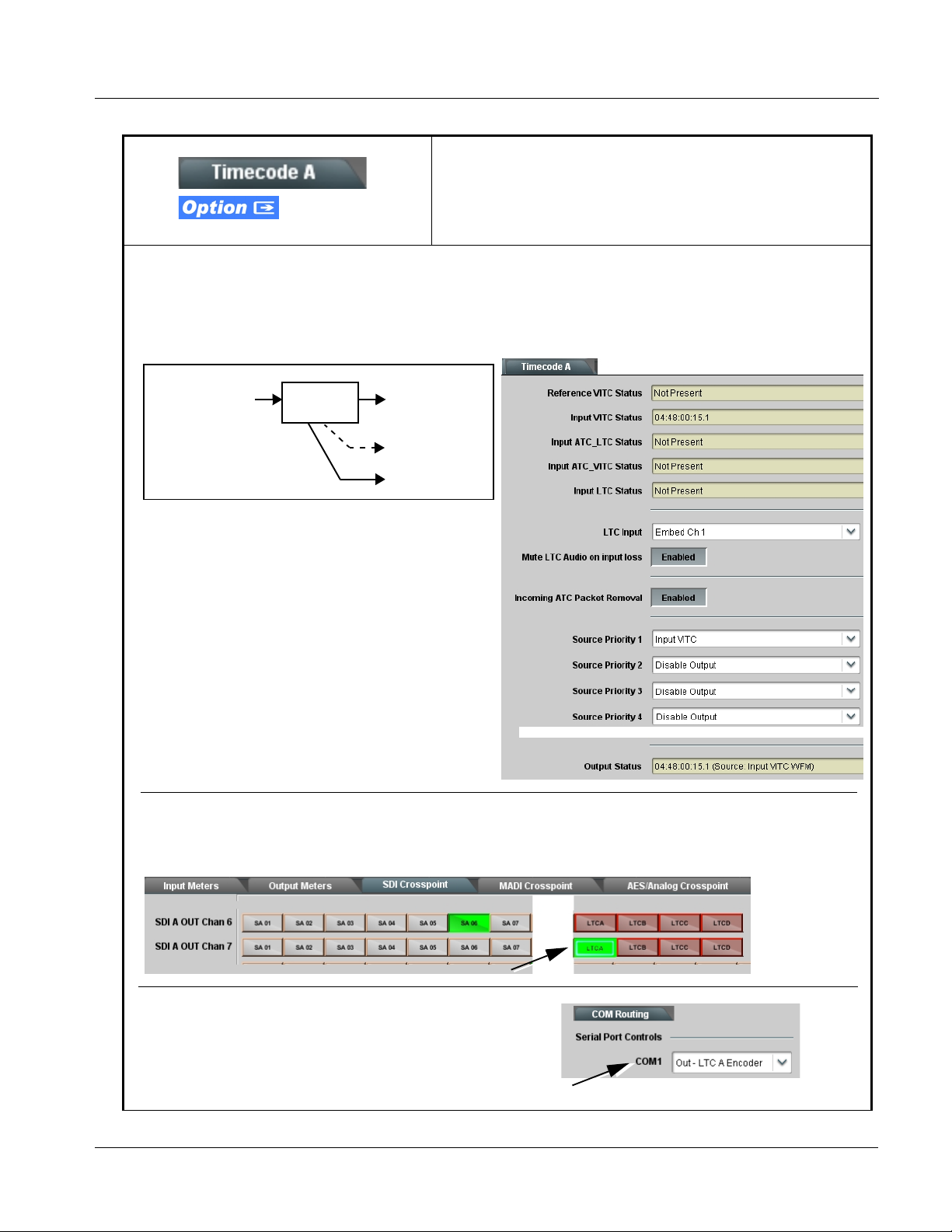
Operating Instructions 9374-Series Function Submenu List and Descriptions
Table 3-1 9374-Series Function Subm enu List — continued
(continued)
+LT C
SMPTE 12M VANC Conversion to Audio/RS-485 Transmit Example
Shown below is an example in which received 525i 5994 SDI video with VBI VITC waveform timecode on SDI A is converted
to Audio/RS-485 LTC and outputted on SDI A Emb Ch 7 and an RS-485 port.
525i 5994 SDI (w/
VITC waveform)
Noting that program material VITC waveform timecode is only
to be used, Source Priority 1 is set to prioritize SDI VITC as
the only choice. Therefore, when VITC waveform is present,
it will be considered as the source that will eventually be
outputted by the card regardless of output format selected.
Output Status shows VITC waveform is being used as
timecode source.
Using the SDI Crosspoint tab controls, SDI A LTC encoder output LTCA is selected as the source for SDI A Emb Ch 7, thereby
outputting LTC on this channel. (If this LTC output is intended for any other audio channel, either AES, MADI, or another video
path embedded channel, it can be applied by selecting LTCA also for other channels as desired.)
Timecode
Proc
SDI 525i 5994
Audio LTC Out
on SDI A
Emb Ch 7
RS-485 LTC
Out on COM 1
• ••
Because COM 1 is to be used for the RS-485 LTC output in this example,
COM 1 is set to Out - LTCA Encoder on the COM Routing tab.
937X- OM (V1.3) 9374-SERIES PRODUCT MANUAL 3-27
Page 60

3 9374-Series Function Submenu List and Descriptions
Table 3-1 9374-Series Function Submenu List — continued
(continued)
+LT C
SMPTE 12M VANC Transfer From SDI-to-SDI Channel Example
Shown below is an example in which received VBI ATC_VITC timecode on SDI A is transferred (copied to) SDI B using the
two RS-485 ports on the card.
SDI A
(w/ATC_VITC
timecode)
(no timecode)
Using the Timecode B tab controls, this channel is set to receive an imported
RS-485 LTC (in this example, jumpered over from LTCA), and prioritize to only
use this timecode.
SDI B
SDI A
Timecode
Proc
SDI A RS-485 LTC Out on COM 1
SDI B RS-485 LTC In on COM 2
SDI B
Timecode
Proc
SDI A Output Video
SDI B Output Video
(w/ copied timecode
import)
The timecode source channel controls (in this example,
Timecode A) are set to receive and insert (output)
ATC_VITC as described earlier in this section.
Using the COM Routing tab, the SDI A LTC encoder
output LTCA is set to output over COM1, while COM2 is
set as an input to receive the LTCA timecode (a jumper
is required between the two ports).
Because no native timecode exists in the SDI B input
stream, and ATC_VITC is desired as an output, the
Timecode B HD ATC_VITC Insertion control is set to
Enabled.
The Output Status display shows that the imported
RS-485 LTC timecode is being used to generate the
timecode output for SDI B.
3-28 9374-SERIES PRODUCT MANUAL 937X-OM (V1.3)
Page 61
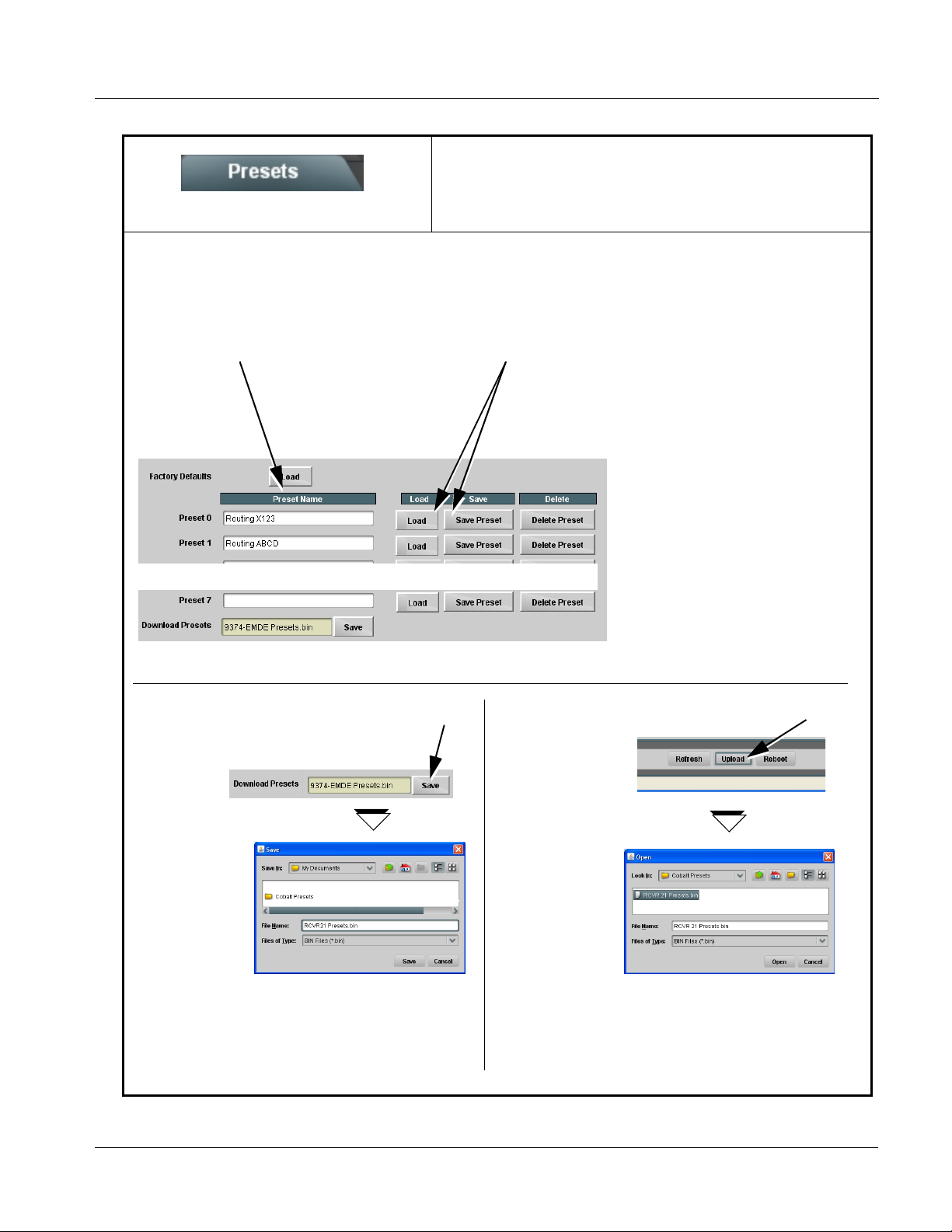
Operating Instructions 9374-Series Function Submenu List and Descriptions
Table 3-1 9374-Series Function Subm enu List — continued
Allows up to seven card user settings configuration
presets to be saved in a Preset and then recalled (loaded)
Presets
Presets allow convenient recall of custom user settings performed on the card. When a preset is invoked, only the setting
changes called by the preset are re-loaded, avoiding unnecessary delay or signal disruption that would otherwise result from a
global control preset change.
The Preset Name field allows entry of names that
are useful in describing the purpose or action of a
particular preset, as shown in the examples here.
(Up to 62 ASCII characters can be entered.)
as desired. All current settings are saved when a Preset
Save is invoked.
• Preset Save stores all current card control settings for the selected
preset (in this example, pressing Save for Preset 0 (“RoutingX123”)
saves all current card control settings to Preset 0.
• Preset Load recalls and applies a saved preset.
Download (save) card presets to a
network computer by clicking
Download Presets – Save at the
bottom of the Presets page.
Browse to a desired
save location (in this
example, My
Documents\Cobalt
Presets).
The file can then be
renamed if desired
(RCVR21 Presets in
this example)
before committing
the save.
Upload (open) card presets from a network
computer by clicking Upload
at the bottom of
DashBoard.
Browse to the location
where the file was saved
on the computer or
drive (in this
example, My
Documents\Cobalt
Presets).
Select the desired
file and click Open
to load the file to the
card.
Note:• Preset transfer between card download and file
upload is on a group basis (i.e., individual presets
cannot be downloaded or uploaded separately).
• After uploading a presets file, engagement of a
desired preset is only assured by pressing the a
Load button for a desired preset.
937X- OM (V1.3) 9374-SERIES PRODUCT MANUAL 3-29
Page 62

3 Troubleshooting
Troubleshooting
This section provides general troubleshooting information and specific
symptom/corrective action for the 9374-Series card and its remote control
interface. The 9374-Series card requires no periodic maintenance in its
normal operation; if any er ror indi ca tion (as described in this section) occurs,
use this section to correct the condition.
Error and Failure Indicator Overview
The 9374-Series card it self and its remote control systems all (to varying
degrees) provide error and failure indications. Depending on how the
9374-Series card is being used (i.e, standalone or network controlled through
DashBoard™, check all available indications in the event of an error or
failure condition. The various 9374-Series card and remote control error and
failure indicators are individually described below.
Note: The descriptions below provide general information for the various status and
error indicators. For specific failures, also use the appropriate subsection
listed below.
• Basic Troubleshooting Checks (p. 3-34)
• 9374-Series Processing Error Troubleshooting (p. 3-34)
• Troubleshooting Network/Remote Control Errors (p. 3-36)
3-30 9374-SERIES PRODUCT MANUAL 937X-OM (V1.3)
Page 63
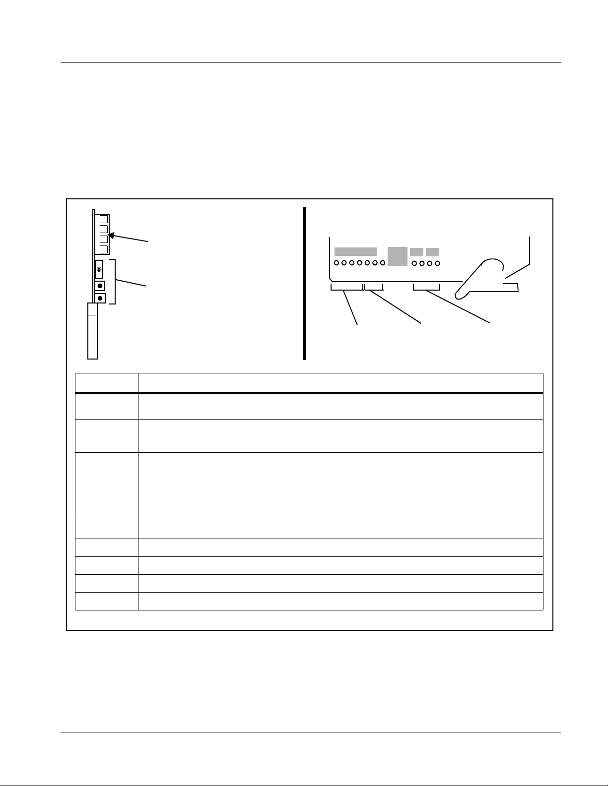
Operating Instructions Troubleshooting
9374-Series Card Edge Status/Error Indicators and Display
Figure 3-5 shows and describes the 9374-Series card edge status indicators
and display. These indicators and t he d ispla y show s tatus and er ro r condi tions
relating to the card itself and remote (network) c ommunications (where
applicable). Because these indicators are part of the card itself and require no
external interface, the indicators are particularly useful in the event of
communications problems with external devices such as network remote
control devices.
4-Character Alphanumeric Display
3G
HD
REF
ERR
RMT
Card Edge Manual Controls
9374
LOCK
Status
Indicators
MENU DEPTH
SD
Input Format
Indicators
Menu Depth
Indicators
Item Function
Display Displays 4-digit abbreviated code showing menu and submenu selections. When in a menu displaying a
Card Edge
Manual
Controls
Input Format
Indicators
Menu Depth
Indicators
RMT LED Blue LED flashes when card is receiving control message from remote network control.
parameter setting, the display shows parametric scalar value (and +/- sign where applicable).
This function is currently reserved.
Three blue LEDs indicate the input signal format being received and locked onto by the card:
• 3G
• HD
• SD
Continuous cycling of the LEDs indicates the card has not locked onto a particular format (as in the case of no
signal input).
This function is currently reserved.
REF LED Blue LED illuminates when card is receiving valid framesync when set up for framesync reference.
LOCK LED B lue LED illuminates when card unable to lock to framesync, or unable to lock to input standard.
ERR LED This function is currently reserved.
Figure 3-5 9374-Series Card Edge Status Indicators and Display
937X- OM (V1.3) 9374-SERIES PRODUCT MANUAL 3-31
Page 64

3 Troubleshooting
DashBoard™ Status/Error Indicators and Displays
Figure 3-6 shows and describes the DashBoard™ status i ndicators and
displays. These indicator icons and displays show status and error conditions
relating to the 9374-Series card itself and remote (network) communications.
Indicator Icon or Display Error Description
Red indicator icon in Card Access/Navigation Tree pane shows card with Error
condition (in this example, the Card Access/Navigation Tree pane shows a general
error issued by the 9374 card in slot 6).
Specific errors are displayed in the Card Info pane (in this example “No connection
to device” indicating 9374 card is not connecting to frame/LAN).
If the card is not connecting to the frame or LAN, all controls are grayed-out.
Gray indicator icon in Card Access/Navigation Tree pane shows card(s) are not
being seen by DashBoard™ due to lack of connection to frame LAN (in this
example, both a 9374 card in slot 6 and the MFC-8320-N Network Controller Card
for its frame in slot 0 are not being seen).
Yellow indicator icon in Card Access /Navigation Tree pane shows card with Alert
condition (in this example, the Card Access/Navigation Tree pane shows a general
alert issued by the MFC-8320-N Network Controller Card).
Clicking the card slot position in the Card Access/Navigation Tree (in this example
Network Controller Card “Slot 0: MFC-8320-N”) opens the Card Info pane for the
selected card. In this example, a “Fan Door Open” specific error is displayed.
Yellow indicator icon in 9374 Video Path Status shows error alert, along with cause
for alert (in this example, the card is receiving SDI streams that are not compatible
with each other as an input pair).
Red indicator icon in 9374 Ref Status shows error alert, along with cause for alarm
(in this example, the selected reference is invalid or missing).
Figure 3-6 DashBoard™ Status Indicator Icons and Displays
3-32 9374-SERIES PRODUCT MANUAL 937X-OM (V1.3)
Page 65
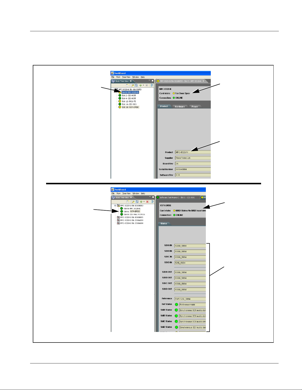
Operating Instructions Troubleshooting
Access the Card Inf o pane fo r a speci fic car d by clic king the c ard slot positio n
in the Card Access/Navigation Tree pane (as shown in the example in Figure
3-7).
By clicking on “Slot 0: MFC-8320-N”
in this example, Card Info is
displayed for frame Network
Controller Card
By clicking on “Slot 6: 9374” in
this example, Card Info is
shown for 9374 card in slot 6
Status for selected card is
shown here (in this
example, connection OK
and “Fan Door Open”
alert)
Card general information
is displayed in lower
portion of Card Info pane
Status for selected
card is shown here
Where applicable,
additional status is
displayed (as shown in
this example)
Figure 3-7 Selecting Specific Cards for Card Info Status Display
937X- OM (V1.3) 9374-SERIES PRODUCT MANUAL 3-33
Page 66

3 Troubleshooting
Basic Troubleshooting Checks
Failures of a general nature (affecting many cards and/or functions
simultaneously), or gross inoperability errors are best addressed first by
performing basic checks before proceeding further. Table 3-2 provides basic
system checks that typically locate the source of most general problems. If
required and applicable, perform further troubleshooting in accordance with
the other troubleshooting tables in this section.
Table 3-2 Basic Troubleshooting Checks
Item Checks
Verify for power presence On both the frame Network Controller Card and the card, in all cases when power is
being properly supplied there is always at least one indicator illuminated. Any card
showing no illuminated indicators should be cause for concern.
Check Cabl e connection
secureness and connecting
points
Card seating within slots Make certain all cards are properly seated within its frame slot. (It is best to assure
Check status indicators and
displays
Troubles hoot by substitution All cards within the frame can be hot-swapped, replacing a suspect card or module
Make certain all ca ble connec tions are ful ly secure (inc luding coa xial cable att ach ment
to cable ferrules on BNC connectors). Also, make certain all connecting points are as
intended. Make certain the selected connecting points correlate to the intended card
inputs and/or outputs. Cabling mistakes are especially easy to make when working
with large I/O modules.
proper seating by ejecting the card and reseating it again.)
On both DashBoard™ and the card edge indicators, red indications signify an error
condition. If a status indicator signifies an error, proceed to the following tables in this
section for further action.
with a known-good item.
9374-Series Processing Error Troubleshooting
T able 3-3 prov ides 9374-Seri es processing troubleshoot ing informati on. If the
card exhibits any of the symptoms listed in Table 3-3, follow the
troubleshooting instructions provided.
In the majority of cases, most errors are caused by simple errors where the
card is not appropriately set for the type of signal being received by the card.
Note: The error indications shown below are typical for the corresponding error
conditions listed. Other error indications not specified here may also be
displayed on DashBoard™ and/or the card edge status indicators.
Note: Where errors are displayed on both the card and network remote controls, the
respective indicators and displays are individually described in this section.
3-34 9374-SERIES PRODUCT MANUAL 937X-OM (V1.3)
Page 67

Operating Instructions Troubleshooting
Table 3-3 Troubleshooting Processing Errors by Symptom
Symptom Error/Condition Corrective Action
• DashBoard™ shows Video
yellow icon and Input Invalid
message in Card Info pane.
• If all inputs missing, card edge
Input Format LEDs show
continuous cycling .
• DashBoard™ shows invalid
in Ref Status message in Card
Info pane.
• DashBoard™ shows Video
Input conflict in Video Path
Status message in Card Info
pane.
Audio embedded from external
MADI or AES sources show
errors or noise/pops.
DashBoard™ response slower
than normal.
Input Meters or Output Meter s do
not display channels as
expected.
®
data outputted on card
Dolby
SDI, AES, or MADI channels not
recognized or decodable as
Dolby.
No video input present Make certain intended video source is
connected to appropriate card video input.
Make certain BNC cable connections between
frame Rear I/O Module for the card and signal
source are OK.
Reference not properly
selected or not being received
(card has reverted to free-run
failover)
Incompatible combinatio n of
SDI formats on SDI inputs A/B
or C/D
MADI audio not synchronous
with video
Too many PPM meters
activated
Input Meters and Output
Meters not enabled or have
timed out
Gain controls set for other than
unity
If external reference is n ot intended to be u sed,
make certain the Reference selection list is set
to appropriate alternate selection as desired.
Refer to Considerations Regarding
Multiple-Channel SDI (p. 3-8). If mu lti ple inpu ts
SDI A/B or SDI C/D are used, inputs must
conform as described.
MADI sources must be fr ame-referenced to
either the video bein g used or a refere nce. AES
audio is sample-rate conver ted to
accommodate minor timing variances.
Received SMPTE 337 (Dolby
AES input is automatically bypassed from the
sample rate converters; this data must be
synchronous to video.
Because the 9374-Series Input Meters and
Output Meters tabs displa y near real-time
dynamic data for many channels, network
traffic can be economized by disabling meters
when not being viewed (the meter transactions
occur whenever a meter tab is enable d,
regardless whether the page is being
displayed).
Use the meter Timeout or Enable/Disable
controls to turn off metering not being used.
Make certain intended Input Meters and/or
Output Meters are enabled, with Display
Status showing “Meters are currently
displaying”.
If channel(s) are carrying Dolby® data, make
certain Gain control s are set at default uni ty
setting. Applying any gain change to a Dolby
stream will corrupt the data.
®
data) over an
937X- OM (V1.3) 9374-SERIES PRODUCT MANUAL 3-35
Page 68

3 Troubleshooting
Troubleshooting Network/Remote Control Errors
Refer to Cobalt® reference guide “COMPASS™ Remote Control User
Guide” (PN 9000RCS-RM) for network/remote control troubleshooting
information.
In Case of Problems
Should any problem arise with this product that was not solved by the
information in this section, please contact the Cobalt Digital Inc. Technical
Support Department.
If required, a Return Material Authorization number (RMA) will be issued to
you, as well as specific shipping instructions. If required, a temporary
replacement item will be made available at a nominal charge. Any shipping
costs incurred are the customer’s responsibility. All products shipped to you
from Cobalt Digital Inc. will be shipped collect.
The Cobalt Digital Inc. Technical Support Department will continue to
provide advice on any product manufactured by Cobalt Digital Inc., beyond
the warranty period without charge, for the life of the product.
See Contact Cobalt Digital Inc. (p. 1-13) in Chapter 1, “Introduction“ for
contact in formation.
3-36 9374-SERIES PRODUCT MANUAL 937X-OM (V1.3)
Page 69

Page 70

Cobalt Digital Inc.
2406 E. University Ave.
Urbana, IL 61802
Voice 217.344.1243 • Fax 217.344.1245
www.cobaltdigital.com
937X-OM (V1.3) Printed in USA
 Loading...