

Page 1

9363
Multi-Format Reference Generator
Product Manual
Cobalt Digital Inc.
2406 E. University Ave.
Urbana, IL 61802
Voice 217.344.1243 • Fax 217.344.1245
www.cobaltdigital.com
9363-OM (V1.2)
Page 2

Copyright
©Copyright 2013, Cobalt Digital Inc. All Rights Reserved.
Duplication or distribution of this manual and any information contained within is strictly prohibited without the express written
permission of Coba lt Digital Inc. This manual and a ny information contained within, may not be re produced, distribute d, or
transmitted in any form, or by any means, for any purpose, without the express written permission of Cobalt Digital Inc.
Reproduction or reverse engineering of software used in this device is prohibited.
Disclaimer
The information in this document has been carefully examined and is believed to be entirely reliable. However, no responsibility
is assumed for inaccuracies. Furthermore, C obalt Digit al Inc. res erves the right to ma ke changes to any pro ducts herein to improve
readability, function, or design. Cobalt Digital Inc. does not assume any liability arising out of the application or use of any
product or circuit described herein.
Trademark Information
Cobalt® is a registered trademark of Cobalt Digital Inc.
COMPASS™ is a trademark of Cobalt Digital Inc.
openGear
®
is a registered trademark of Ross Video Limited. DashBoard™ is a trademark of Ross Video Limited.
Congratulations on choosing the Cobalt
line of modular processing a nd conversion gear for broadcast TV e nvironments. The Cobalt Digital Inc. line
includes video decoders and encoders, audio embedders and de-embedders, distribution amplifiers, format
converters, remote contro l system s and much more. Shou ld you have qu estions pe rtainin g to the instal lation or
operation of your 9363, please contact us at th e contact inform ation on the front cove r.
®
9363 Mutli-Format Reference Generator. The 9363 is part of a full
Manual No.: 9363-OM
Document
Version: 1.2
Release Date: December 30, 2013
9363-OM (V1.2)
Page 3

Table of Contents
Chapter 1 Introduction . . . . . . . . . . . . . . . . . . . . . . . . . . . . . . . . . . . . . . . . . . . 1-1
Overview ................................................................................................................ 1-1
Manual Conventions............................................................................................... 1-2
Warnings, Cautions, and Notes .................................................................. 1-2
Labeling Symbol Definitions...................................................................... 1-3
Safety Summary ..................................................................................................... 1-3
Warnings..................................................................................................... 1-3
Cautions...................................................................................................... 1-3
9363 Functional Description .................................................................................. 1-4
Available Output Formats/Rates ................................................................ 1-4
Notes Regarding Color Framing................................................................. 1-8
AES/Word Clock Output............................................................................ 1-8
User Control Interface ................................................................................ 1-8
AES Audio Output Channel Status Data.................................................... 1-9
9363 Rear I/O Modules .............................................................................. 1-9
Technical Specifications....................................................................................... 1-10
Warranty and Service Information ....................................................................... 1-12
Cobalt Digital Inc. Limited Warranty....................................................... 1-12
Contact Cobalt Digital Inc.................................................................................... 1-13
Chapter 2 Installation and Setup . . . . . . . . . . . . . . . . . . . . . . . . . . . . . . . . . . . 2-1
Overview ................................................................................................................ 2-1
Setting Card Jumpers.............................................................................................. 2-1
Installing a Rear I/O Module.................................................................................. 2-2
9363 Rear I/O Modules .............................................................................. 2-2
Installing a Rear I/O Module...................................................................... 2-3
Installing the 9363 Into a Frame Slot ..................................................................... 2-4
Setting Up 9363 Network Remote Control ............................................................ 2-5
9363-OM (V1.2) 9363 PRODUCT MANUAL i
Page 4

Chapter 3 Operating Instructions. . . . . . . . . . . . . . . . . . . . . . . . . . . . . . . . . . . 3-1
Overview................................................................................................................. 3-1
Accessing the 9363 Card Using DashBoard™ Remote Control ............................ 3-1
9363 Function Submenu List and Descriptions...................................................... 3-2
Setup Controls ............................................................................................ 3-3
Alarm Controls .......................................................................................... 3-6
Wings Insertion Synchronization Example ............................................................ 3-7
Card-Edge Control/Display .................................................................................... 3-8
Troubleshooting...................................................................................................... 3-9
Error and Failure Indicator Overview......................................................... 3-9
Basic Troubleshooting Checks ................................................................... 3-9
Troubleshooting Network/Remote Control Errors ..................................... 3-9
In Case of Problems.................................................................................... 3-9
9363-OM (V1.2) 9363 PRODUCT MANUAL ii
Page 5

Overview
Chapter 1
Chapter 1 Introduction
This manual provides installation and operating instructions for the 9363
Multi-Format Reference Generator card (also referred to herein as the 9363).
This manual consists of the following chapters:
• Chapter 1, “Introduction” – Pro vides informa tion about th is manual
and what is covered. Als o pr ovi des general information re gar di ng the
9363.
• Chapter 2, “Installation and Setup” – Provides instructions for
installing the 9363 in a frame, and optionally installing a 9363 Rear
I/O Module.
• Chapter 3, “Operating Instructions” – Provides overviews of
operating controls and instructions for using the 9363.
This chapter contains the following information:
• Manual Conventions (p. 1-2)
• Safety Summary (p. 1-3)
• 9363 Functional Description (p. 1-4)
• Technical Specifications (p. 1-10)
• Warranty and Service Information (p. 1-12)
• Contact Cobalt Digital Inc. (p. 1-13)
9363-O M (V1.2) 9363 PRODUCT MANUAL 1-1
Page 6

1 Manual Conventions
Manual Conventions
In this manual, display messages and connectors are shown using the exact
name shown on the 9363 itself. Examples are provided below.
• Card-edge display messages are shown like this:
9363
• Connector names are shown like this: OUT 1A
In this manual, the terms below are applicable as follows:
• 9363 refers to the 9363 Multi-Format Reference Generator card.
• Frame refers to the 8321 (or similar) frame that houses the Cobalt
COMPASS™ cards.
• Device and/or Card refers to a COMPASS™ card.
• System and/or Video System refers to the mix of interconnected
production and terminal equipment in which the 9363 and other
COMPASS™ cards operate.
®
Warnings, Cautions, and Notes
Certain items in this manual are highlighted by special messages. The
definitions are provided below.
Warnings
Warning messages indicate a possible hazard which, if not avoided, could
result in personal injury or death.
Cautions
Caution messages indicate a problem or incorrect practice which, if not
avoided, could result in improper operation or damage to the product.
Notes
Notes pro vide suppl emental information to the accompanying text. Notes
typically precede the text to which they apply.
1-2 9363 PRODUCT MANUAL 9363-OM (V1.2)
Page 7
Introduction Safety Summary
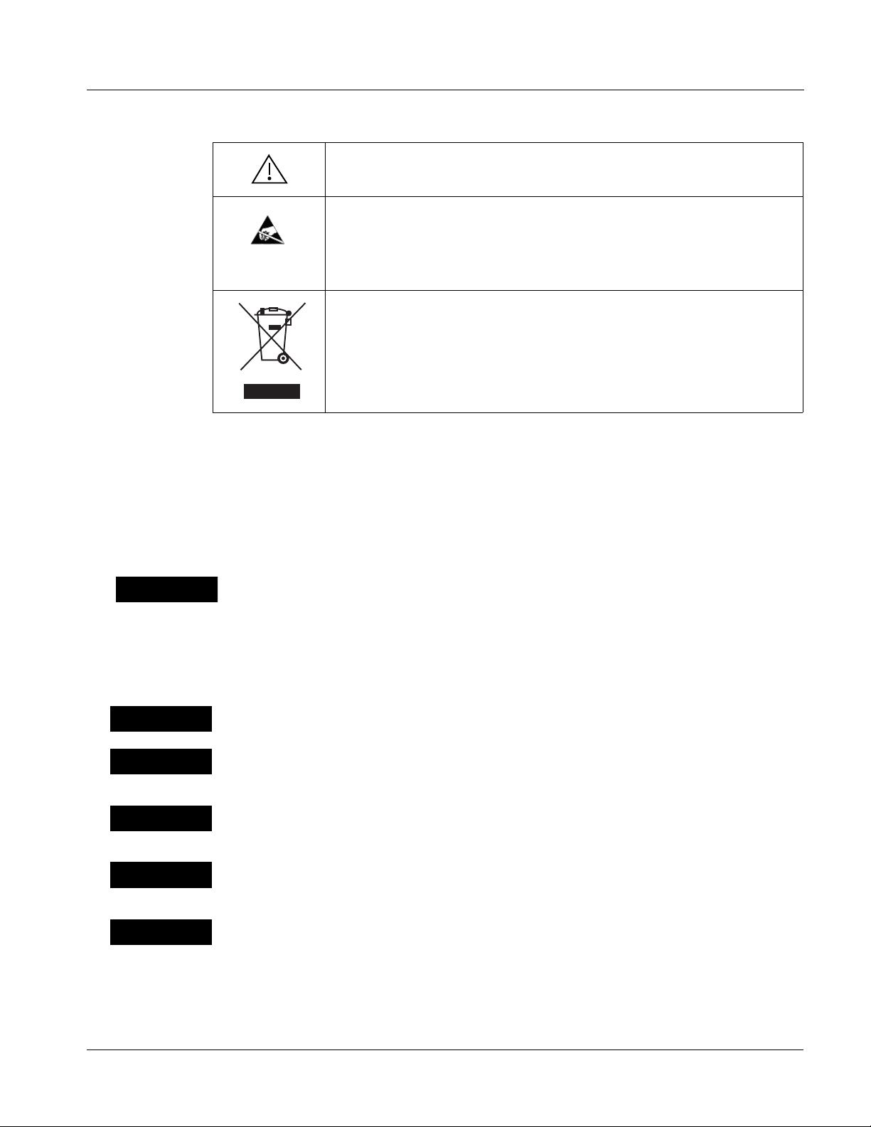
Labeling Symbol Definitions
Attention, consult accompanying documents.
Electronic device or assembly is susceptible to damage from an ESD
event. Handle only using appropriate ESD prevention practices.
If ESD wrist strap is not available, handle card only by edges and avoid
contact with any connectors or components.
Symbol (WEEE 2002/96/EC)
For product disposal, ensure the following:
• Do not dispose of this product as unsorted municipal waste.
• Collect this product separately.
• Use collection and return systems available to you.
Safety Summary
Warnings
! WARNING !
Cautions
CAUTION
CAUTION
CAUTION
CAUTION
T o re duce risk of electr ic shock do not remove line voltage service barrier cover on frame
equipment containing an AC power supply. NO USER SERVICEABLE PARTS INSIDE.
REFER SERVICING TO QUALIFIED SERVICE PERSONNEL.
This device is intended for environmentally controlled use only in appropriate video
terminal equipment operating environments.
This product is intended to be a component product of an openGear™ frame. Refer to the
openGear™ frame Owner's Manual for important safety instructions regarding the proper
installation and safe operation of the frame as well as its component products.
Heat and power distribution requirements within a frame may dictate specific slot
placement of cards. Cards with many heat-producing components should be arranged to
avoid areas of excess heat build-up, particularly in frames using only convection cooling.
If required, make certain Rear I/O Module(s) is installed before installing the 9363 into the
frame slot. Damage to card and/or Rear I/O Module can occur if module installation is
attempted with card already installed in slot.
CAUTION
9363-OM (V1.2) 9363 PRODUCT MANUAL 1-3
If card resists fully engaging in rear I/O mod ule mating connec tor, check for alignment and
proper insertion in slot tracks. Damage to card and/or rear I/O module may occur if
improper card insertion is attempted.
Page 8
1 9363 Functional Description
9363 Functional Description
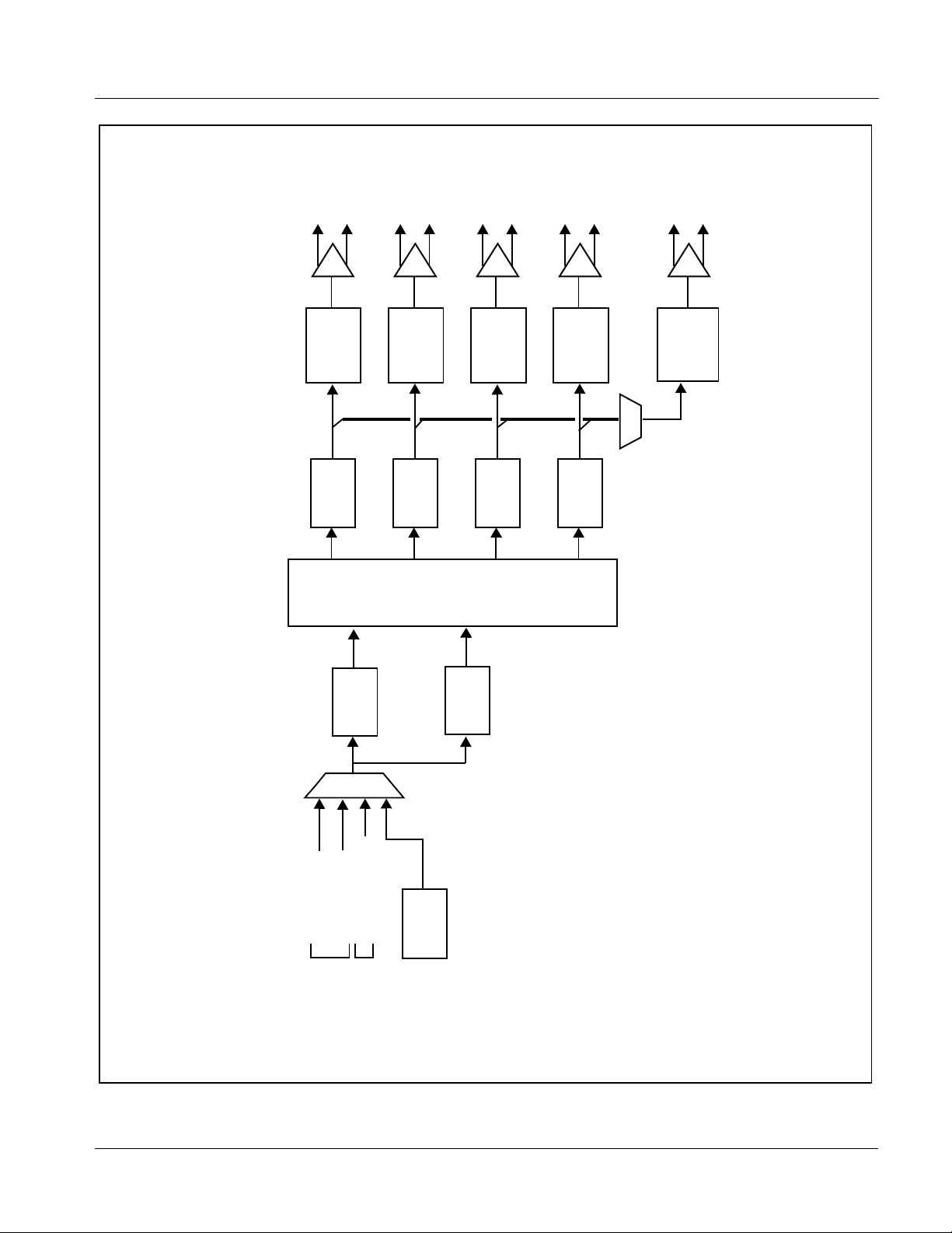
Figure 1-1 shows a functional block diagram of the 9363. In addition to
providing four reference output signal pairs, the 9363 also provides a
synchronized AES/word clock output.
The 9363 can select from external references from openGear™ frame
reference distrib uted signals
received via a rear module BNC connector.
The 9363 is compatible with the input formats and rates (including AES and
basic word clock signals), and provides multiple output formats and rates as
listed in Table 1-1. Using the card’s internal generator source, the 9363 can
also generate reference outputs without using any external reference.
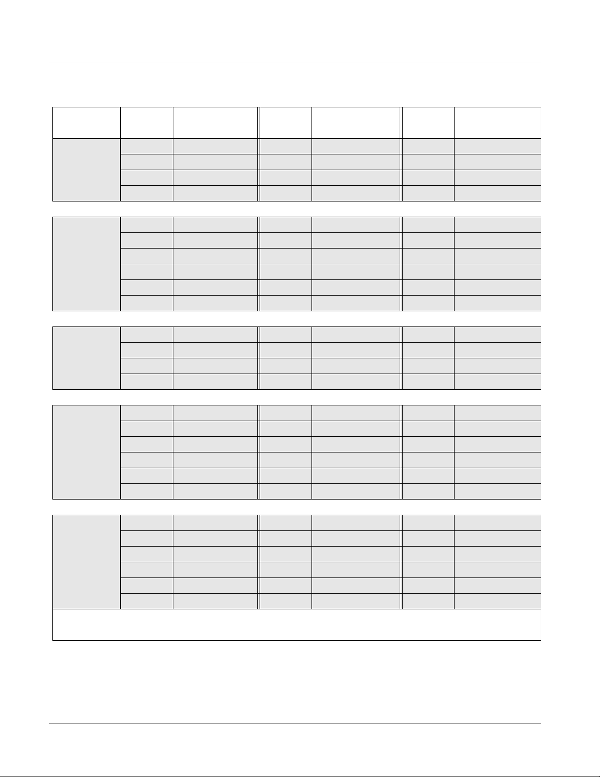
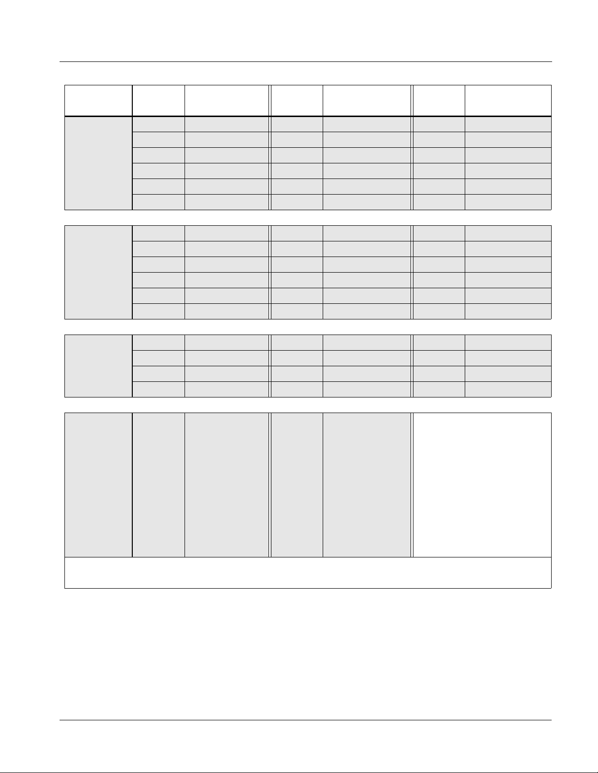
Available Output Formats/Rates
Table 1-1 lists the available output formats/rates for input references
supported by the 9363. Note in Table 1-1 that when converting between
formats and rates, various lock states exist for different conversions (for
example, when going from a progressive-format reference to an interlaced
format output, the card cannot provide an output that is assured always to
indicate an odd or even field). Described below are the three types of lock
states provided for various conversions provided by the card.
Ref 1 or Ref 2, or Ext Ref (Local) which is
Genlock
Source
Output
Output is synchronized with source
reference in bot h fram e and field (where
applicable)
Field Lock
When an interlaced format is deri ved from a
progressive source, field lock is achieved.
However, timing does not reliably mark odd or
even field.
Indicates a fixed relationship between the
source reference and output clock rates only;
but no relation ship betw een sourc e referenc e
and frame timing can be inferred.
Four pairs of outputs are provided, with each pair
OUT 4A / OUT 4B being independently configurable as black burst or tri-level
Clock Lock
OUT 1A / OUT 1B thru
reference outputs. Each of the outputs can be independently configured for
any rate/format related to the source reference format, and can additionally be
independently delayed or advanced (in terms of vertical lines or horizontal
pixels) relative to the source timing. If the card internal reference clock source
is used, the four output pairs operate as described above, with the internal
source instead serving as the timing basis.
1-4 9363 PRODUCT MANUAL 9363-OM (V1.2)
Page 9
Introduction 9363 Functional Description
OUT 1A
OUT 1B
OUT 2A
OUT 2B
OUT 3A
OUT 3B
OUT 4A
OUT 4B
AES/
WC OUT 1
AES/
WC OUT 2
Multi-
Format
Converter
Offset
Timing
Multi-
Format
Converter
Offset
Timing
Sync
Pulse
Multi-
Format
Converter
Offset
Timing
Multi-
Format
Converter
Offset
Timing
AES/Word
Clock
Driver
Generator
Sync
Separator
AES
Receiver
(NOTE 3)
Frame Ref 1 IN
Frame Ref 2 IN
Ext (Local) Ref IN
From Rear
From Frame
Module BNC
Source
Internal
capability. Practical input/output signal availability is
determined by Rear I/O Module used. Refer to “9363
Rear I/O Modules,” 1-9 for more information.
the four generator outputs.
external (Local) ref in. Typically, external (Local) ref
2. AES/Word Clock outputs can be sourced from any of
Notes: 1. Signal connections shown depicts full input/output
in is used for AES clock input source.
3. AES receiver can obtain input from frame ref or
9363V1.1BD
Figure 1-1 9363 Functional Block Diagram
9363-OM (V1.2) 9363 PRODUCT MANUAL 1-5
Page 10
1 9363 Functional Description
Table 1-1 9363 Output Formats
Input
Format
480i 5994,
1080i 5994
576i 50,
1080i 50
720p 5994,
1080p 2997
Output
Format/
Rate
480i 5994 Genlock 1080 i5994 Genlock AES Genlock
720p 5994 Genlock 1080p 2997 Genlock Word Clock Genlock
720p 2997 Genlock 1080p 2398 Clock Lock
720p 2398 Clock Lock 1080pSF 2398 Clock Lock
576i 50 Genlock 1080 i50 Genlock AES Genlock
720p 60 Clock Lock 1080p 30 Clock Lock Word Clock Genlock
720p 50 Genlock 1080p 25 Genlock
720p 30 Clock Lock 1080p 24 Clock Lock
720p 25 Genlock 1080pSF 24 Clock Lock
720p 24 Clock Lock 1080i 60 Clock Lock
480i 5994 Field Lock 1080 i5994 Field Lock AES Genlock
720p 5994 Genlock 1080p 2997 Genlock Word Clock Genlock
720p 2997 Genlock 1080p 2398 Clock Lock
720p 2398 Clock Lock 1080pSF 2398 Clock Lock
Lock State
Output
Format/
Rate
Lock State
Output
Format/
Rate
Lock State
576i 50 Field Lock 1080i 60 Clock Lock AES Genlock
720p 60 Clock Lock 1080 i50 Field Lock Word Clock Genlock
720p 50,
1080p 25
720p 60,
1080p 30
Notes: 1. Format/rates listed in bold indicate format/rates also available using Internal source.
2. “NTSC” and “PAL” in this manual informally refer to 480i 5994 and 575i 50 SD-SDI video formats, respectively.
720p 50 Genlock 1080p 30 Clock Lock
720p 30 Clock Lock 1080p 25 Genlock
720p 25 Genlock 1080p 24 Clock Lock
720p 24 Clock Lock 1080pSF 24 Clock Lock
576i 50 Clock Lock 1080i 60 Field Lock AES Genlock
720p 60 Genlock 1080 i50 Clock Lock Word Clock Genlock
720p 50 Clock Lock 1080p 30 Genlock
720p 30 Genlock 1080p 25 Clock Lock
720p 25 Clock Lock 1080p 24 Clock Lock
720p 24 Clock Lock 1080pSF 24 Clock Lock
1-6 9363 PRODUCT MANUAL 9363-OM (V1.2)
Page 11
Introduction 9363 Functional Description
Table 1-1 9363 Output Formats — continued
Input
Format
1080i 60
1080p 24,
1080pSF 24
1080p 2398,
1080pSF 2398
Output
Format/
Rate
576i 50 Clock Lock 1080i 60 Genlock AES Genlock
720p 60 Genlock 1080 i50 Clock Lock Word Clock Genlock
720p 50 Clock Lock 1080p 30 Genlock
720p 30 Genlock 1080p 25 Clock Lock
720p 25 Clock Lock 1080p 24 Clock Lock
720p 24 Clock Lock 1080pSF 24 Clock Lock
720p 60 Clock Lock 1080i 60 Clock Lock AES Genlock
720p 50 Clock Lock 1080 i50 Clock Lock Word Clock Genlock
720p 30 Clock Lock 1080i 30 Clock Lock
720p 25 Clock Lock 1080p 25 Clock Lock
720p 24 Genlock 1080p 24 Genlock
720p 5994 Clock Lock 1080i 5994 Clock Lock AES Genlock
720p 2997 Clock Lock 1080p 2997 Clock Lock Word Clock Genlock
720p 25 Clock Lock 1080p 2398 Genlock
720p 2398 Genlock 1080pSF 2398 Genlock
Lock State
Output
Format/
Rate
1080pSF 24 Genlock
Lock State
Output
Format/
Rate
Lock State
480i 5994
576i 50
720p 60
720p 5994
720p 50
AES,
Word Clock
Notes: 1. Format/rates listed in bold indicate format/rates also available using Internal source.
2. “NTSC” and “PAL” in this manual informally refer to 480i 5994 and 575i 50 SD-SDI video formats, respectively.
720p 30
720p 2997
720p 25
720p 2398
1080i 60
1080i 5994
1080i 50
Genlock
1080p 60
1080p 5994
1080p 50
1080p 30
1080p 2997
1080p 25
1080p 24
1080pSF 24
1080pSF 2398
AES
Word Clock
Genlock
9363-OM (V1.2) 9363 PRODUCT MANUAL 1-7
Page 12

1 9363 Functional Description
Notes Regarding Color Framing
When an NTSC or PAL SD reference is received by the 9363, and one or
more outputs are set to the same format/rate as the received input, th e color
frame of these outputs match the reference color framing. It should be noted
that this initial relationship will not necessarily follow any changes in the
received reference that are external to this card. However, the 9363
re-establishes color framing re-lock upon:
• Card power-up or reboot
• Change in reference (either by manuall y togg ling r efer ence se lect ion,
or by removing and re-applying the received reference)
• Manually changing/manipulating the output timing offset for an
output channel.
AES/Word Clock Output
The 9363 can provide an AES output signal (suitable as a DARS signal)
which is timing referenced to any of the four card reference outputs. When set
for an AES output, the AES output can be set to various frequencies and
levels.
User Control Interface
The 9363 uses DashBoard™ as the normal graphical user interface for the
card, similar to other Cobalt
®
COMPASS™ cards.
Using DashBoard™, the 9363 an d other c ards insta lled in openGear™ frames
®
such as the Cobalt
8321-C Frame can be controlled from a computer and
monitor. DashBoard™ allows users to view all frames on a network with
control and monitoring for all populated slots inside a frame. This simplifies
the setup and use of numerous modules in a large installation and offers the
ability to centralize monitoring. Cards define their controllable parameters to
DashBoard™, so the control interface is always up to date.
The DashBoard™ software can be downloaded from the Cobalt Digital Inc.
website: www.cobaltdigital.com
(enter “DashBoard” in the search window).
The DashBoard™ user interface is described in Chapter 3,“Operating
Instructions”.
Note: If network remote control is to be used for the frame and the frame has not yet
been set up for remote control, Cobalt
User Guide (PN 9000RCS-RM) provides thorough information and
step-by-step instructions for setting up network remote control of
COMPASS™ cards using DashBoard™. (Cobalt
OGCP-9000/CC Remote Control Panel product manuals have complete
instructions for setting up remote control using a Remote Control Panel.)
Download a copy of this guide by clicking on the Support>Reference Docu-
ments link at www.cobaltdigital.com and then select DashBoard Remote
Control Setup Guide as a download, or contact C obalt
Cobalt Digital Inc. (p. 1-13).
®
reference guide Remote Control
®
OGCP-9000 and
®
as listed in Contact
1-8 9363 PRODUCT MANUAL 9363-OM (V1.2)
Page 13

Introduction 9363 Functional Description
AES Audio Output Channel Status Data
Table 1-2 lists the channel status information that is encoded into the AES
audio data outputted by the 9363.
Note: The AES channel status settings outputted by the card are non-configurable.
Table 1-2 AES Audio Output Channel Status Data
Byte Bit/Function Configured Setting
00 –
10-3 –
20-2 –
30-7 – Multi-channel Modes Undefined (0)
40-1 –
50-7 – Reserved Unused (0)
6-9 ASCII Source ID Unused (0)
10-13 ASCII Destination ID Unused (0)
14-17 Local Sample Address Unused (0)
18-22 Time of Day Unused (0)
22 0-7 – C Data Reliability All status bytes marked as Reliable
Professional or Consumer use of Channel Status Block
1 –
Normal Audio or Non-Normal Audio
2-4 –
Emphasis
Lock Indication
5 –
Sampling Rate
6-7 –
Channel Mode
4-7 –
User Bit Mode
Aux Bit Usage
3-5 –
Sample Word Length
6-7 –
Alignment Level
Digital Audio Reference Signal (DARS)
2 –
Reserved
3-6 –
Sampling Frequency
7 –
Sampling Frequency Scaling Flag
Professional (1)
Normal Audio (0)
No Emphasis (100)
Not Indicated (0)
48 kHZ (01)
2-channel Mode (0001)
192-bit (0001)
24-bit audio sample; aux bit audio (001)
24-bits (101)
Not Indicated (00)
Not a reference (0)
0
Not Indicated (0000)
No Scaling (0)
23 0-7 – CRC Calculated CRC
9363 Rear I/O Modules
The 9363 physically interfaces to system video connections at the rear of its
frame using a Rear I/O Module.
All inputs and out puts (excep t fra me di stri buted refe ren ce si gnals
and
Frame Ref 2) shown in the 9363 Functional Block Diagram (Figure 1-1)
enter and exit the card via the card edge backplane connector. The
Rear I/O Module breaks out the 9363 card edge connections to BNC
connectors that interface with other components and systems in the signal
chain. See “Installation”, Chapter 2 for Rear I/O Module connections.
9363-OM (V1.2) 9363 PRODUCT MANUAL 1-9
Frame Ref 1
Page 14

1 Technical Specifications
Technical Specifications
Table 1-3 lists the technical specifications for the 9363 Multi-Format
Reference Generator card.
Table 1-3 Technical Specifications
Item Characteristic
Part number, nomenclature 9363 Multi-Format Reference Generator
Installation/usage environment Intended for installation and usage in frame meeting openGear™
modular system definition.
Power consumption < 6 Watts maximum
Environmental:
Operating temperature:
Relative humidity (operating or storage):
Frame communication 10/100 Mbps Ethernet with Auto-MDIX.
32° – 104° F (0° – 40° C)
< 95%, non-condensing
Analog Video Output (Reference Output
Channels)
Standards Accommodated:
SMPTE 274M, 296M, and 170M
ITU-R BT.470-6 (PAL-B)
Number of Channels:
4x2 (with RM20-9363-A)
4X1 (with RM20-9363-A/S)
Signal Level:
1 Vp-p
DC Offset:
< 50 mV
Output Impedance:
75 Ω
Return Loss:
> 40 dB to 30 MHz
Signal Level:
1 Vp-p
Internal Reference Frequency Stability:
1ppm initial; 4.6ppm/10 years
Thermal Stability:
± 0.25ppm (0° to 70° C)
1-10 9363 PRODUCT MANUAL 9363-OM (V1.2)
Page 15

Introduction Technical Specifications
Table 1-3 Technical Specifica tions — continued
Item Characteristic
AES/Word Clock Output Number of Channels:
1x2 (with RM20-9363-A)
1 (with RM20-9363-A/S)
Signal Level:
1 Vp-p
DC Offset:
< 50 mV
Output Impedance:
75 Ω
Return Loss:
> 25 dB to 10 MHz
Sample Rate (AES Output):
48 kHz
Local (External) Reference Input Number of Channels:
1
Input Impedance:
75 Ω terminated or hi-z
Return Loss:
> 40 dB to 10 MHz
Minimum Input (AES/Word Clock mode):
100 mVp-p
Maximum Input (AES/Word Clock mode):
4.0 Vp-p
Sample Rate (AES Input):
48 kHz
Standards Accommodated (Ref Input Mode):
SMPTE 274M, 296M, and 170M
ITU-R BT.470-6 (PAL-B)
Signal Level (Ref Input Mode):
1.0 Vp-p
9363-OM (V1.2) 9363 PRODUCT MANUAL 1-11
Page 16

1 Warranty and Service Information
Warranty and Service Information
Cobalt Digital Inc. Limited Warranty
This product is warranted to be free from defects in material and workmanship for a period of five (5)
years from the date of shipment to the original purchaser, except that 4000, 5000, 6000, 8000 series
power supplies, and Dolby
material and workmanship for a period of one (1) year.
Cobalt Digital Inc. 's (“Cobalt”) sole obligation under this warranty shall be limited to, at its option, (i)
the repair or (ii) replacement of the product, and the determinati on of whether a defect is covered under
this limited warranty shall be made at the sole discretion of Cobalt.
This limited warranty applies onl y to the original end-purchaser of the pr oduct, and is not assigna ble or
transferrable therefrom. This warranty is limited to defects i n material a nd workman shi p, and shal l not
apply to acts of God, accidents, or negligence on behalf of the purchaser, and shall be voided upon the
misuse, abuse, alteration, or modification of the product. Only Cobalt authorized factory
representatives are authorized to make repairs to the product, and any unauthorized attempt to repair
this product shall immediately void the warranty. Please contact Cobalt Technical Support for more
information.
®
modules (where applicable) are warranted to be free from defects in
To facilitate the resolution of warranty related issues , Cobalt recommends registering the product by
completing and returning a product registration form. In the event of a warrantable defect, the
purchaser shall notify Cobalt with a description of the problem, and Cobalt shall provide the purchaser
with a Return Material Authorization (“RMA”). For return, defective product s should be double boxed,
and sufficiently protected, in the original packaging, or equivalent, and shipped to the Cobalt Factory
Service Center, postage prepaid and insured for the purchase price. The purchaser should include the
RMA number, description of the problem encountered, date purchased, name of dealer purchased
from, and serial number with the shipment.
Cobalt Digital Inc. Factory Service Center
2406 E. University Avenue Office: (217) 344-1243
Urbana, IL 61802 USA Fax: (217) 344-1245
www.cobaltdigital.com Email: info@cobaltdigital.com
THIS LIMITED WARRANTY IS EXPRESSLY IN LIEU OF ALL OTHER WARRANTIES
EXPRESSED OR IMPLIED, INCLUDING THE WARRANTIES OF MERCHANTABILITY AND
FITNESS FOR A PARTICULAR PURPOSE AND OF ALL OTHER OBLIGATIONS OR
LIABILITIES ON COBALT'S PART. ANY SOFTWARE PROVIDED WITH, OR FOR USE WITH,
THE PRODUCT IS PROVIDED “AS IS.” THE BUYER OF THE PRODUCT ACK NOWLEDGES
THAT NO OTHER RE PRESENTATIONS W ERE MADE OR RELIED UPON WITH RESPECT TO
THE QUALITY AND FUNCTION OF THE GOODS HEREIN SOLD. COBALT PRODUCTS ARE
NOT AUTHORIZED FOR USE IN LIFE SUP PORT APPLICATIONS.
COBALT'S LIABILITY, WHETHER IN CONTRACT, TORT, WARRANTY, OR OTHERWISE, IS
LIMITED TO THE REPAIR OR REPLACEMENT, AT ITS OPTION, OF ANY DEFECTIVE
PRODUCT, AND SHALL IN NO EVENT INCLUDE SPECIAL, INDIRECT, INCIDENTAL, OR
CONSEQUENTIAL DAMAGES (INCL UDING LOST PROFITS), EVEN IF IT HAS BEEN
ADVISED OF THE POSSIBILITY OF SUCH DAMAGES.
1-12 9363 PRODUCT MANUAL 9363-OM (V1.2)
Page 17

Introduction Contact Cobalt Digital Inc.
Contact Cobalt Digital Inc.
Feel free to contact ou r th oro ugh and professional support representatives for
any of the following:
• Name and address of your local dealer
• Product information and pricing
• Technical support
• Upcoming t rade show information
Phone: (217) 344-1243
Fax: (217) 344-1245
Web: www.cobaltdigital.com
General Information: info@cobaltdigital.com
Technical Support: support@cobaltdigital.com
9363-OM (V1.2) 9363 PRODUCT MANUAL 1-13
Page 18

This page intentionally blank
1-14 9363 PRODUCT MANUAL 9363-OM (V1.2)
Page 19

Overview
Setting Card Jumpers
Chapter 2
Chapter 2 Installation and Setup
This chapter contains the following information:
• Setting Card Jumpers (p. 2-1)
• Installing the 9363 Into a Frame Slot (p. 2-4)
• Installing a Rear I/O Module (p. 2-2)
• Setting Up 9363 Network Remote Control (p. 2-5)
The AUX I/O connector on the 936 3 Rear I/ O Module is a mult i-pur pose BNC
port that can be set as either a
or an AES/Word Clock (
positions.
Local (External) BNC reference source input,
AES/WC OUT) output depending on the jumper
(See Figure 2-1.) Jumpers
function as descri bed bel ow. Depending on function desired, set t hese jumpe rs
before installing the card in a frame.
• JP1 (EXT TERM) – Sets card aux BNC connector to use card internal
75-ohm termination. This position is the default position and is recommended unless the connection is to be looped within a 75-ohm externally
terminated chain.
• JP2 (REF IN / AES OUT) – Sets card aux BNC connector to either serve as
an extra (Local/External) reference inpu t (facto ry def ault po sitio n), or se rve
as an AES/word clock output (AES/WC OUT).
Note: Default factory settings shown.
JP1 (Ext Ref)
OFF ON
•••
JP2
REF AES
IN OUT
•••
Figure 2-1 9363 Termination and AUX I/O BNC Jumpers
JP1 and JP2 set the AUX I/O BNC connector
Rear of Card
9363-O M (V1.2) 9363 PRODUCT MANUAL 2-1
Page 20

2 Installing a Rear I/O Module
Installing a Rear I/O Module
9363 Rear I/O Modules
Table 2-1 shows and describes the full assortment of Rear I/O Modules
specifically for use with the 9363.
Table 2-1 9363 Rear I/O Modules
9363 Rear I/O Module Description
RM20-9363-A Provides the following conne cti on s:
• Four pairs of output reference channels
(
OUT 1A / OUT 1B thru OUT 4A / OUT 4B)
• Dedicated AES/word clock output (
• Multi-function port (
AUX I/O). Serves as either extra
reference input or AES/word clock output copy.
Note: Refer to Setting Card Jumpers (p. 2-1) for
setting connector function.
AES/WC OUT)
RM20-9363-A.PNG
RM20-9363-A/S Split Rear Module. Provides each of the following
connections for two 9363 cards:
• Four output reference channels
OUT 1 thru OUT 4)
(
• Multi-function port (
AUX I/O). Serves as either extra
reference input or AES/word clock output.
Note: Refer to Setting Card Jumpers (p. 2-1) for
setting connector function.
RM20-9363-AS.PNG
2-2 9363 PRODUCT MANUAL 9363-OM (V1.2)
Page 21

Installation and Setup Installing a Rear I/O Module
Installing a Rear I/O Module
Install a Rear I/O Module as follows:
1. On the frame, determine the slot in which the 9363 is to be installed.
2. In the mounting area corresponding to the slot location, install
Rear I/O Module as shown in Figure 2-2.
Align and engage mounting tab on Rear
I/O Module with the module seating slot
1
on rear of frame chassis.
DSCN3483A.JPG
Hold top of Rear I/O Module flush against
frame chassis and start the captive screw.
2
Lightly tighten captive screw.
DSCN3487A.JPG
Figure 2-2 Rear I/O Module Installation
9363-OM (V1.2) 9363 PRODUCT MANUAL 2-3
Page 22

2 Installing the 9363 Into a Frame Slot
Installing the 9363 Into a Frame Slot
CAUTION
Heat and power distribution requirements within a frame may dictate specific
slot placement of cards. Cards with many heat-producing components should
be arranged to avoid areas of excess heat build-up, particularly in frames
using only convection cooling.
CAUTION
This device contains semiconductor devices which are
susceptible to serious damage from Electrostatic
Discharge (ESD). ESD damage may not be immediately
apparent and can affect the long-term reliability of the
device.
Avoid handling circuit boards in high static environments
such as carpeted areas, and when wearing synthetic fiber
clothing. Always use proper ESD handling precautions
and equipment when working on circuit boards and
related equipment.
Note: A Rear I/O Module is required before cabling can be connected. Refer to
Installing a Rear I/O Module (p. 2-2) for rear I/O module installation procedure.
CAUTION
If required, make certain Rear I/O Module(s) is installed before installing the
9363 into the frame slot. Damage to card and/or Rear I/O Module can occur if
module installation is attempted with card already installed in slot.
Note: Check the packaging in which the 9363 was shipped for any extra items such
as a Rear I/O Module connection label. In some cases, this label is shipped
with the card and to be installed on the Rear I/O connector bank corresponding to the slot location of the card.
Install the 9363 into a frame slot as follows:
1. Determine the slot in which the 9363 is to be installed.
2. Open the frame front access panel.
3. While holding the card by the card edges, align the card such that the
plastic ejector tab is on the bottom.
4. Align the card with the top and bottom guides of the slot in which the
card is being installed.
5. Gradually slide the card into the slot. When resistance is noticed, g ently
continue pushing the card until its rear printed circuit edge terminals
engage fully into the rear I/O module mating connector.
2-4 9363 PRODUCT MANUAL 9363-OM (V1.2)
Page 23

Installation and Setup Setting Up 9363 Network Remote Control
CAUTION
If card resists fully engaging in rear I/O module mating connector, check for
alignment and proper insertion in slot tracks. Damage to card and/or rear I/O
module may occur if improper card insertion is attempted.
Verify that the card is fully engaged in rear I/O module mating
6.
connector.
7. Close the frame front access panel.
8. Connect the input and output cables as shown in Installing a Rear I/O
Module (p. 2-3).
9. Repeat steps 1 through 8 for other 9363 cards.
Note: Frame 1 and Frame 2 reference signals are received by the card over a refer-
ence bus on the card frame, and not on any card rear I/O module connectors.
The frame has BNC connectors labeled REF 1 and REF 2 which receive the
reference signal from an external source such as a house distribution.
Note: To remove a card, press down on the ejector tab to unseat the card from the
rear I/O module mating connector. Evenly draw the card from its slot.
10. If network remote control is to be used for the frame and the frame has
not yet been set up for remo te co ntr ol , perf or m se tup in acc ordance with
Setting Up 9363 Network Remote Control (p. 2-5).
Note: If installing a card in a frame already equipped for, and connected to
DashBoard™, no network setup is required for the card. The card will be discovered by DashBoard™ and be ready for use.
Setting Up 9363 Network Remote Control
Perform remote control setup in accordance with Cobalt® reference guide
“Remote Control User Guide” (PN 9000RCS-RM).
Note: • If network remote control is to be used for the frame and the frame has not
yet been set up for remote control, Cobalt
Control User Guide (PN 9000RCS-RM) provides thorough information and
step-by-step instructions for setting up network remote control of
COMPASS™ cards using DashB oar d™. (Cobalt
OGCP-9000/CC Remote Control Panel product manuals have complete
instructions for setting up remote control using a Remote Control Panel.)
Download a copy of this guide by clicking on the
Support>Reference Documents link at www.cobaltdigital.com and then
select DashBoard Remote Control Setup Guide as a download, or contact
®
Cobalt
as listed in Contact Cobalt Digital Inc. (p. 1-13).
®
reference guide Remote
®
OGCP-9000 and
• If installing a card in a frame already equipped for, and connected to
DashBoard™, no network setup is required for the card. The card will be discovered by DashBoard™ and be ready for use.
9363-OM (V1.2) 9363 PRODUCT MANUAL 2-5
Page 24

This page intentionally blank
2-6 9363 PRODUCT MANUAL 9363-OM (V1.2)
Page 25

Overview
Chapter 3
Chapter 3 Operating Instructions
This chapter contains the following information:
If you are already familiar
with using DashBoard or a
Cobalt Remote Control
Panel to control Cobalt
cards, please skip to 9363
Function Submenu Li st and
Descriptions (p. 3-2).
• Accessing the 9363 Card Using DashBoard™ Remote
Control (p. 3-1)
• 9363 Function Submenu List and Descriptions (p. 3-2)
• Card-Edge Control/Display (p. 3-8)
• Troubleshooting (p. 3-9)
Accessing the 9363 Card Using Das hBoard™ Remote Control
1. On the computer connected to the frame LAN, open DashBoard™.
2. As shown below, in the left side Basic View Tree locate the Network
Controller Card associated with the frame containing the 9363 card to be
accessed (in this example, “MFC-8320-N SN: 00108053”).
DB_ACCESS1.PNG
9363-O M (V1.2) 9363 PRODUCT MANUAL 3-1
Page 26

3 9363 Function Submenu List and Descriptions
3. As shown below, expand the tree to access the cards within the frame.
Click on the card to be accessed (in this example,
.
“Slot 6: CDI-9363”).
9363_DB_ACCESS2A.PNG
When the ca rd is accessed in DashBoard™ its function submenu screen
showing tabs for each function is displayed.
9363 Function Submenu List and Descriptions
T abl e 3-1 in div idual ly lists and descri bes ea ch 9363 f uncti on submenu a nd its
related list selections, controls, and parameters. Where helpful, examples
showing usage of a function are also provided. Table 3-1 is primarily based
upon using DashBoard™ to access each function and its corresponding
submenus and parameters.
Note: If DashBoard is unavailable, the card edge controls can be used to access all
controls described here. Refer to Card-Edge Control/Display (p. 3-8) for using
card edge controls.
3-2 9363 PRODUCT MANUAL 9363-OM (V1.2)
Page 27

Operating Instructions 9363 Function Submenu List and Descriptions
Table 3-1 9363 Function Submenu List
Provides controls for selecting input reference source
Setup Controls
• Input Reference Source Select Selects source to be used as basic timing reference input as follows:
and configuring the four reference output pairs.
• Frame 1: Selects Frame 1 distributed reference signal as base
source.
• Frame 2: Selects Frame 2 distributed reference signal as base
source.
• Local: Selects Rear I/O Module External input BNC input as base
source.
Note: Card jumper JP2 must be set to REF IN position for this
input to work (this is the default factory position). See Setting
Card Jumpers (p. 2-1) in Chapter 2, “Installation” for more
information.
• Internal: Selects the card internal reference as base source.
• Reference Format Display Display reference format and rate of external (frame or external) reference
Setting Format/Rate Setting Format/Rate
60Hz 1080i 60 29.97Hz 1080p 29.97
59.94Hz 480i 5994 25Hz 1080p 25
50Hz 576i 50 24Hz 1080p 24
30Hz 1080p 30 23.98Hz 1080p 23.98
source. Provides selection of format when Internal source is selected.
• When an external reference source (Frame 1, Frame 2, or
External (Local)) is selected, displays received format and
rate.
• When the Internal reference source is being used (or when an
AES or Word Clock external input is received), Reference
Rate drop-down allows selection of internal base references
from choices listed below.
9363-OM (V1.2) 9363 PRODUCT MANUAL 3-3
Page 28

3 9363 Function Submenu List and Descriptions
Table 3-1 9363 Function Submenu List — continued
(continued)
• Reference Video Output Controls For each of the card’s four reference output pairs, provides independent
• Format Select Provides multiple format and rate choices for respective output channel.
•
•
•
controls for output format/rate, as well as horizontal and vertical delay
controls. Also shows lock status for each channel selection.
Each of the four output channels have identical, independent controls
which are described below.
Note: Refer to Available Output Formats/Rates (p. 1-4) in Chapter 1,
“Introduction” for available formats for each input format supported and
other notes.
• Horizontal/Vertical Offset Controls Provides controls to offset output video sync relative from input or internal
source (Horizontal Delay values in pixels; Vertical Delay values in lines).
• Positive setting delay-offsets output reference by selected value
(e.g., in NTSC Black output mode for Vertical Delay setting of 1,
output sync is delayed 1 line.
• Negative (wrap-around) setting advance-offsets output reference by
selected value (e.g., in NTSC Black output mode for Vertical Delay
setting of 524 (same as “-1”), output sync coincides with 524th line
(525 minus 1 line) of input reference.
Note: All offset control values are relative to the selected input reference
source.
3-4 9363 PRODUCT MANUAL 9363-OM (V1.2)
Page 29

Operating Instructions 9363 Function Submenu List and Descriptions
Table 3-1 9363 Function Submenu List — continued
(continued)
• Compatibility Status Indicator Shows compatibility of output format choice in regards to received input or
selected internal source.
• Genlock: (see below)
• Field Lock: (see below)
• Clock Lock: (see below)
• Incompatible: Indicates an output format selection that is
incompatible in respect to the received or selected internal source
(e.g., a PAL (50 Hz) output selection when using a 59.94 Hz-based
source).
Note: See Available Output Formats/Rates (p. 1-4) in Chapter 1,
“Introduction” for available formats for each input format supported and
other notes.
Genlock
Field Lock
Clock Lock
Source
Output
Output is synchronized with source
reference in both frame and field (where
applicable)
When an interlaced format is derived from a
progressive source, field lock is achieved.
However, timing does not reliably mark odd or
even field.
Indicates a fixed relationship between the
source referen ce and ou tput clock rates only ;
but no relati onship bet ween so urce ref erence
and frame timing can be inferred.
• Audio Output Format Select Selects audio output produced from received or internal base timing
source as follows:
• Off: AES output is muted.
• AES: AES/WC OUT BNC output produces an AES output.
Note: • See Table 1-2, “AES Audio Output Channel Status Data (p.
1-9)” in Chapter 1, “Introduction” for AES data
specifications for this output mode.
• Card jumper JP2 must be set to AES OUT position for this
output to work (this is not the default factory position). See
Setting Card Jumpers (p. 2-1) in Chapter 2, “Installation”
for more information.
• Word Clock: AES/WC OUT BNC output produces basic word clock
output.
9363-OM (V1.2) 9363 PRODUCT MANUAL 3-5
Page 30

3 9363 Function Submenu List and Descriptions
Table 3-1 9363 Function Submenu List — continued
(continued)
• Audio Output Co-Timing Source Select Selects the card output to which the AES or word clock output is
• AES Audio Output Level Controls When AES output is used, provides level, mute, and audio tone frequency
referenced.
Note: Any offset applied to the output using the Horizontal/Vertical
Offset Controls is applied to the AES/word clock output.
controls.
• AES Level sets output level (in dBFS; default is -20 dBFS sine wave).
• AES Tone selects from the frequencies shown, and mute.
Note: Mute setting simply mutes the audio tone on the AES signal.
The output is a valid functional AES signal in all other
aspects.
Provides controls for setting DashBoard card status
alarms indicating proces si ng status condi tio ns .
Alarm Contr ols
• Reference Alarm
With Reference Alarm checked, conditions related to received reference status are propagated to the DashBoard card signal
status display (in this example, no reference signal received on selected input reference).
• Color Burst Presence Alarm
With Color Burst Detection checked, if selected received reference does not contain color burst, this status is propagated to
the DashBoard card signal status display (in this example, a black burst signal is being received on selected input reference).
• Output Incompatibility Alarm
With Video Output Compatibility for output channel checked, if selected output format on corresponding output channel is
incompatible with received (or selected internal) reference, this status is propagated to the DashBoard card signal status
display.
3-6 9363 PRODUCT MANUAL 9363-OM (V1.2)
Page 31

Operating Instructions Wings Insertion Synchronization Example
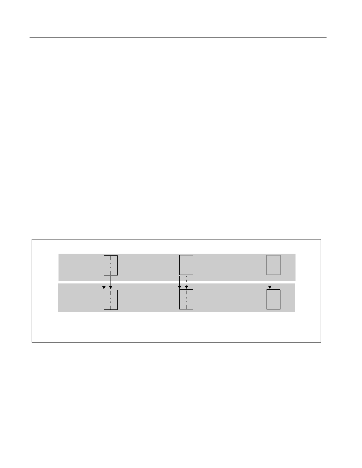
Wings Insertion Synchronization Example
Figure 3-1 shows an example of using the 9363 to receive a house reference
and provide coincident and a locked offset reference such that wings video
insertion can be delayed, allowing the wings video to align with the program
video, considering the inherent delay of the wings inserter.
Program Video
Output 1 (Ref
House Ref
In this example, the wings video input to the Wings Inserter device must be delayed by 152 lines in order to compensate for
program video delay inherent in the inserter. The house reference is provided undelayed to the basic reference inputs of the
program video framesync and wings inserter framesync input.
The wings video path here is equipped with its own framesync, which receives the delay offset reference from the 9363, thereby
maintaining a precise, stable offset regardless of any drift in the house reference.
Shown below are the 9363 DashBoard control settings for this setup.
Frame 1
9363
Wings Video
Output 2 (Ref
Output 3 (Ref
Program Video
Framesync
)
t0
)
t0
+ Inserter Delay)
t0
Wings Video
Framesync
Pgm Vid IN
FS Ref IN
Wings Vid IN
Wings
Inserter
Added required delay (152 lines)
for wings video feed
Figure 3-1 Wings Insertion Synchronization Example
9363-OM (V1.2) 9363 PRODUCT MANUAL 3-7
Page 32

3 Card-Edge Control/Display
Card-Edge Control/Display
Note: If using DashBoard remote control, ignore this section. Use of these controls
is required only if DashBoard is unavailable.
Figure 3-2 shows and describes the 9363 card edge controls, indicators, and
display. Refer to 9363 Function Submenu List and Descriptions (p. 3-2) for
detailed descriptions and selections available for the controls described in
Figure 3-2.
Menu Select Switch
AUDIO
VIDEO 1
VIDEO 2
VIDEO 3
VIDEO 4
Item Select
Alphanumeric Display
Toggle Switch
REFERENCE
9363
Status
Indicators
Item Function
Display Displays 4-digit abbreviated code showing menu and submenu selections. When in a menu displaying a
Menu Select
Switch
Item Select
Switch
REFERENCE
LED
VIDEO 1 thru
VIDEO 4
LEDs
parameter setting, the display shows parametric scalar value (and +/- sign where applicable).
Selects card menu as follows:
0 – Home (card info read-only display)
1 – Input Reference Source Select
2 – Reference Rate Display/Select
3 – Output Channel Select
4 – Output Format Select (for output selected in menu 3)
5 – Output Vert Delay (for output selected in menu 3)
6 – Output Horiz Select (for output selected in menu 3)
7 – Audio Output Format
8 – Audio Output Co-Timing Source Select
9 – Audio Output Tone/Mute Select
A – AES Audio Output Level
When toggled up or down, selects available item choices for menu selected using Menu Select switch. Refer to
Table 3-1, “9363 Function Submenu List (p. 3-3)” for item s.
• Green – indicates card is receiving valid reference using selected external source
• Orange – indicates card is set to use internal source
• Off – no reference is present for selected external source
LED corresponding to output channels 1 thru 4 indicate:
• Green (solid) – Output channel is outputting genlock condition
• Green (blinking) – Output channel is outputting condition other than genlock
AUDIO LED • Green (solid) – AES output is outputting valid AES signal
• Green (blinking) – Output channel is outputting word clock
• Off – AES or word clock is user disabled
Figure 3-2 9363 Card Edge Controls
3-8 9363 PRODUCT MANUAL 9363-OM (V1.2)
Page 33

Operating Instructions Troubleshooting
Troubleshooting
This section provides general troubleshooting information and specific
symptom/c orrective action for the 9363 card and its remote control interface.
The 9363 card requires no periodic maintenance in its normal operation; if
any error indication (as described in this section) occurs, use this section to
correct the condition.
Error and Failure Indicator Overview
The 9363 card itself and its remote control systems all (to varying degrees)
provide error and failure indications. Depending on how the 9363 card is
being used (i.e, standalone or network controlled through DashBoard™),
check all available indications in the event of an error or failure condition.
Red indicators in DashBoard typically signify a condition where the card is
lacking a required input, or controls are improperly set for the mode(s)
selected.
Basic Troubleshooting Checks
Failures of a general nature (affecting many cards and/or functions
simultaneously), or gross inoperability errors are best addressed first by
performing basic checks before proceeding further. Table 3-2 provides basic
system checks that typically locate the source of most general problems.
Troubleshooting Network/Remote Control Errors
Refer to Cobalt® reference guide “Remote Control User Guide” (PN
9000RCS-RM) for network/remote control troubleshooting information.
In Case of Problems
Should any problem arise with this product that was not solved by the
information in this section, please contact the Cobalt Digital Inc. Technical
Support Department.
If required, a Return Material Authorization number (RMA) will be issued to
you, as well as specific shipping instructions. If required, a temporary
replacement item will be made available at a nominal charge. Any shipping
costs incur r ed are the customer’s responsibility. All products shipped to you
from Cobalt Digital Inc. will be shipp ed collect.
The Cobalt Digital Inc. Technical Support Department will continue to
provide advice on any product manufactured by Cobalt Digital Inc., beyond
the warranty period without charge, for the life of the product.
See Contact Cobalt Digi tal Inc. (p. 1-13) in Chapter 1, “Introduction“ for
contact information.
9363-OM (V1.2) 9363 PRODUCT MANUAL 3-9
Page 34

3 Troubleshooting
Table 3-2 Basic Troubleshooting Checks
Item Checks
Verify pow er presence and
characteristics
Check Cable connection
secureness and connecting
points
Card seating within slots Make certain all cards are properly seated within its frame slot. (It is best to
Check status indicators and
displays
Troubleshoot by
substitution
On both the frame Network Controller Card and the 9363, in all cases when
power is being properly supplied there is always at least one indicator
illuminated. Any card showing no illuminated indicators should be cause for
concern.
Make certain all cable connections are fully secure (including coaxial cable
attachment to cable ferrules on BNC connectors). Also, make certain all
connecting points are as intended. Make certain the selected connecting
points correlate to the intended card inputs and/or outputs. Cabling mistakes
are especially easy to make when working with large I/O modules.
assure proper seating by ejecting the card and reseating it again.)
On DashBoard™, red indications typically signify an error condition. If a status
indicator signifies an error, proceed to the following tables in this section for
further action.
All cards within the frame can be hot-swapped, replacing a suspect card or
module with a known-good item.
3-10 9363 PRODUCT MANUAL 9363-OM (V1.2)
Page 35

Page 36

Cobalt Digital Inc.
2406 E. University Ave.
Urbana, IL 61802
Voice 217.344.1243 • Fax 217.344.1245
www.cobaltdigital.com
9363-OM (V1.2) Printed in USA
 Loading...