

Page 1
9362
HD/SD-SDI Test Signal Generator
with Text Overwrite, SDI Input Frame Capture/Store,
AFD/Timecode Support, and Fail-Safe Mode
Product Manual
Cobalt Digital Inc.
2406 E. University Ave.
Urbana, IL 61802
Voice 217.344.1243 • Fax 217.344.1245
www.cobaltdigital.com
9362-OM (V4.1)
Page 2

Copyright
©Copyright 2013, Cobalt Digital Inc. All Rights Reserved.
Duplication or distribution of this manual and any information contained within is strictly prohibited without the express written
permission of Coba lt Digital Inc. This manual and a ny information contained within, may not be re produced, distribute d, or
transmitted in any form, or by any means, for any purpose, without the express written permission of Cobalt Digital Inc.
Reproduction or reverse engineering of software used in this device is prohibited.
Disclaimer
The information in this document has been carefully examined and is believed to be entirely reliable. However, no responsibility
is assumed for inaccuracies. Furthermore, C obalt Digit al Inc. res erves the right to ma ke changes to any pro ducts herein to improve
readability, function, or design. Cobalt Digital Inc. does not assume any liability arising out of the application or use of any
product or circuit described herein.
Trademark Information
Cobalt® is a registered trademark of Cobalt Digital Inc.
COMPASS
openGear
®
and FUSION3G® are registered trademarks of Cobalt Digital Inc.
®
is a registered trademark of Ross Video Limited. DashBoard™ is a trademark of Ross Video Limited.
Congratulations o n choosing the Co balt
Input Frame Capture/Store, A FD/Timecode Support, and Fail-Safe Mode. The 9362 is part of a full line o f
modular processing and conversion gear for broadcast TV environments. The Cobalt Digital Inc. line includes
video decoders and encode rs, audio embedders and de-embedde rs, distribution amplifiers , format converters,
remote control systems and much more. Should you have questions pertaining to the installation or operation of
your 9362, please contact us at the contact information on the front cover.
®
9362 HD/SD-SDI Test Signal Generator with Text Overwrite, SDI
Manual No.: 9362-OM
Document Version: V4.1
Release Date: December 30, 2013
Applicable for
Firmware Version
2773
(or greater):
Description of
- Revise manual for minor edits.
product/manual
changes:
9362-OM (V4.1)
Page 3

Table of Contents
Chapter 1 Introduction . . . . . . . . . . . . . . . . . . . . . . . . . . . . . . . . . . . . . . . . . . . 1-1
Overview ................................................................................................................ 1-1
9362 Card Software Versions and this Manual...................................................... 1-2
Cobalt Reference Guides........................................................................................ 1-2
Manual Conventions............................................................................................... 1-3
Warnings, Cautions, and Notes .................................................................. 1-3
Labeling Symbol Definitions...................................................................... 1-4
Safety Summary ..................................................................................................... 1-4
Warnings..................................................................................................... 1-4
Cautions...................................................................................................... 1-4
9362 Functional Description .................................................................................. 1-5
9362 Input/Output Formats ........................................................................ 1-5
TSG Description......................................................................................... 1-5
Embedded Audio Groups 1–4 Controls...................................................... 1-8
User Control Interface ................................................................................ 1-9
9362 Rear I/O Modules ............................................................................ 1-11
Audio and Video Formats Supported by the 9362................................... 1-11
Technical Specifications....................................................................................... 1-12
Warranty and Service Information ....................................................................... 1-14
Cobalt Digital Inc. Limited Warranty....................................................... 1-14
Contact Cobalt Digital Inc.................................................................................... 1-15
Chapter 2 Installation and Setup . . . . . . . . . . . . . . . . . . . . . . . . . . . . . . . . . . . 2-1
Overview ................................................................................................................ 2-1
Installing the 9362 Into a Frame Slot ..................................................................... 2-1
Installing a Rear I/O Module.................................................................................. 2-3
Setting Up 9362 Network Remote Control ............................................................ 2-5
9362-OM (V4.1) 9362 PRODUCT MANUAL i
Page 4

Chapter 3 Operating Instructions . . . . . . . . . . . . . . . . . . . . . . . . . . . . . . . . . . . 3-1
Overview................................................................................................................. 3-1
Control and Display Descriptions........................................................................... 3-1
Function Submenu/Parameter Submenu Overview .................................... 3-2
DashBoard™ User Interface ....................................................................... 3-3
Accessing the 9362 Card via Remote Control........................................................ 3-3
Accessing the 9362 Card Using DashBoard™ ........................................... 3-3
Checking 9362 Card Information............................................................................ 3-5
Ancillary Data Line Number Locations and Ranges .............................................. 3-7
9362 Function Submenu List and Descriptions...................................................... 3-8
AFD ............................................................................................................ 3-9
Embedded Audio Group 1/2 and 3/4 TSG Audio Controls ..................... 3-10
Test Signal Generator ............................................................................... 3-12
Timecode Generator ................................................................................. 3-14
Tone Generator ......................................................................................... 3-16
Presets ...................................................................................................... 3-16
Troubleshooting .................................................................................................... 3-19
Error and Failure Indicator Overview....................................................... 3-19
Basic Troubleshooting Checks.................................................................. 3-23
9362 Processing Error Troubleshooting.................................................... 3-24
Troubleshooting Network/Remote Control Errors.................................... 3-25
In Case of Problems .................................................................................. 3-25
ii 9362 PRODUCT MANUAL 9362-OM (V4.1 )
Page 5

Overview
Chapter 1
Chapter 1 Introduction
This manual provides installati on and o per at ing instr uct ions for the
9362 HD/SD-SDI Test Signal Generator with Text Overwrite, SDI Input
Frame Capture/Sto re, AFD/Timecode Support , and Fail -Safe Mode card (also
referred to herein as the 9362).
This manual consists of the following chapters:
• Chapter 1, “Introduction” – Pro vides informa tion about th is manual
and what is covered. Als o pr ovi des general information regarding the
9362.
• Chapter 2, “Installation and Setup” – Provides instructions for
installing the 9362 i n a fr ame, and option ally i nsta lling 9362 Rear I/O
Modules.
• Chapter 3, “Operating Instructions” – Provides overviews of
operating controls and instructions for using the 9362.
This chapter contains the following information:
• 9362 Card Software Versions and this Manual (p. 1-2)
• Manual Conventions (p. 1-3)
• Safety Summary (p. 1-4)
• 9362 Functional Description (p. 1-5)
• Technical Specifications (p. 1-12)
• Warranty and Service Information (p. 1-14)
• Contact Cobalt Digital Inc. ( p. 1-15)
9362-OM (V4. 1) 9362 PRODUCT MANUAL 1-1
Page 6

1 9362 Card Software Versions and this Manual
9362 Card Software Versions and this Manual
When applicable, Cobalt Digital Inc. provides for continual product
enhancements through software updates. As such, functions described in this
manual may pertain specifically to cards loaded with a particular software
build.
The Software Version of your card can be ch eck ed by vi ewi ng the Card Info
menu in DashBoard™. See Checking 9362 Card Information (p. 3-5) in
Chapter 3, “Operating Instructio ns” for more infor mation. You can then check
our website for the lates t software version currently released for the card as
described below.
Check our website and proceed as follows if your card’s software does not
match the latest versi on:
Card Software earlier than
latest version
Card Software newer than
version in manual
Card is not loaded with the latest software. Not all
functions and/or specified performance described in
this manual may be available.
You can update your card with new Update software by
going to the Support>Firmware Do wnloads link at
www.cobaltdigital.com. Download “Firmware Update
Guide”, which provides simple instructions for
downloading the latest firmware for your card onto your
computer, and then uploading it to your card through
DashBoard™.
Software updates are field-installed without any
need to remove the card from its frame.
A new manual is expediently released whenever a
card’s software is updated and specifications
and/or functionality have changed as compared to
an earlier version (a new manual is not necessarily
released if specifications and/or functionality have not
changed). A manual earlier than a card’s softw a re
version may not completely or accurately describe all
functions available for your card.
If your card shows features not described in this
manual, you can check for the latest manual (if
applicable) and download it by going to the card’s web
page on www.cobaltdigital.com.
Cobalt Reference Guides
From the Cobalt® web home page, go to Support>Referen ce Docum ents for
easy to use guides covering network remote control, card firmware updates,
example card processing UI setups and other topics.
1-2 9362 PRODUCT MANUAL 9362-OM (V4.1)
Page 7

Introduction Manual Conventions
Manual Conventions
In this manual, display messages and connectors are shown using the exact
name shown on the 9362 itself. Examples are provided below.
• Card-edge display messages are shown like this:
TSG
• Connector names are shown like this: SDI IN
In this manual, the terms below are applicable as follows:
• 9362 refers to the 9362 HD/SD-SDI Test Signal Generator with Text
Overwrite, SDI Input Frame Capture/Store, AFD/Timecode Support,
and Fail-Safe Mode card.
Warnings, Cautions, and Notes
Certain items in this manual are highlighted by special messages. The
definitions are provided bel ow.
Warnings
Warning messages indicate a possible hazard which, if not avoided, could
result in pe rsonal injury or death.
Cautions
Caution messages indicate a problem or incorrect practice which, if not
avoided, could result in improper operation or damage to the product.
• Frame refers to the HPF-9000, OG3-FR, 8321, or similar 20-slot
frame that houses Cobalt
• Device and/or Card refers to a COMPASS
• System and/or Video System refers to the mix of interconnected
®
or other cards.
®
card.
production and terminal equipment in which the 9362 and other
COMPASS
®
cards operate.
Notes
Notes provide supplemental information to the accompanying text. Notes
typically precede the text to which they apply.
9362-OM (V4.1) 9362 PRODUCT MANUAL 1-3
Page 8
1 Safety Summary
Labeling Symbol Definitions
Attention, consult accompanying documents.
Electronic device or assembly is susceptible to damage from an ESD
event. Han dle only using appropriate ESD prevention practices.
If ESD wrist strap is not available, handle card only by edges and avoid
contact with any connectors or components.
Symbol (WEEE 2002/96/EC)
For product disposal, ensure the following:
• Do not dispose of this product as unsorted municipal waste.
• Collect this product separately.
• Use collection and return systems available to you.
Safety Summary
Warnings
! WARNING !
Cautions
CAUTION
CAUTION
CAUTION
CAUTION
T o redu ce risk of electr ic shock do not remove line voltage service barrier cover on frame
equipment containing an AC power supply. NO USER SERVICEABLE PARTS INSIDE.
REFER SERVICING TO QUALIFIED SERVICE PERSONNEL.
This device is intended for environmentally controlled use only in appropriate video
terminal equipment operating environments.
This product is intended to be a component product of an openGear® frame. Refer to the
openGear frame Owner's Manual for important safety instructions regarding the proper
installation and safe operation of the frame as well as its component products.
Heat and power distribution requirements within a frame may dictate specific slot
placement of cards. Cards with many heat-producing components should be arranged to
avoid areas of excess heat build-up, particularly in frames using only convection cooling.
If required, make certain Rear I/O Module(s) is installed before installing the 9362 into the
frame slot. Damage to card and/or Rear I/O Module can occur if module installation is
attempted with card already installed in slot.
CAUTION
1-4 9362 PRODUCT MANUAL 9362-OM (V4.1)
If card resists fully engaging in r ear I/O module mating connector, check for alignment and
proper insertion in slot tracks. Damage to card and/or rear I/O module may occur if
improper card insertion is attempted.
Page 9

Introduction 9362 Functional Description
9362 Functional Description
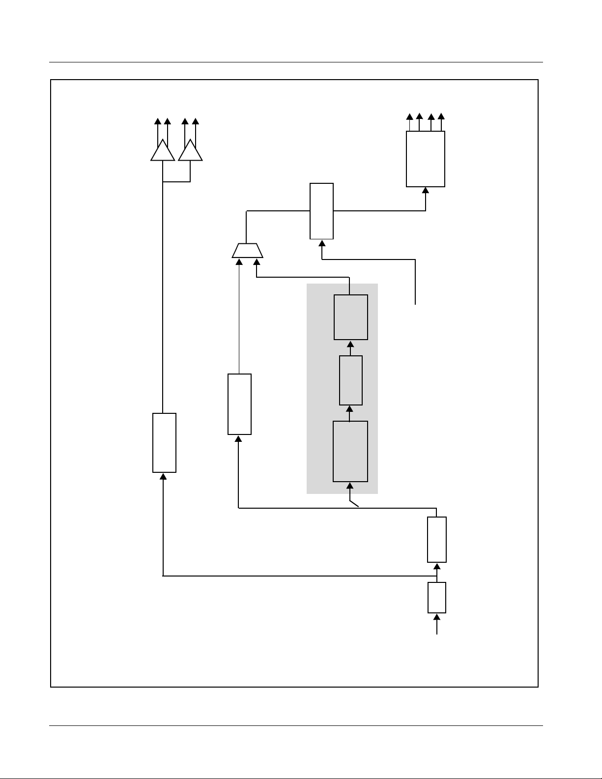
Figure 1-1 shows a functional block diagram of the 9362. With a valid input
present, the card passes input SDI and all ancillary data unaffected. In the
event of loss of input SDI, the card automatically outputs a Te st Signal
Generator (TSG) selected pattern, selectable tones or silence on all four
groups of embedded audio, and can output timecode data generated from the
card. The card also can capture and store a frame received on the program
video input to be used as a pattern. A text overlay can be applied to the TSG
output frame. The te st signa l generat or output can be ma nually in voked at an y
time. The 9362 also handles AFD code detection/ insertion available when
outputting program video.
As such, the 9362 can pr ovi de t es t pattern failover whe n used with a live SDI
stream, while also pr ovidi ng text ID/pa tter n gener ation /timec ode as a dis crete
standalone source.
Note: Some of the functions described below are available only when using the
9362 Input/Output Formats
TSG Description
DashBoard™, or Cobalt
user interfaces. Refer to User Control Interface (p. 1-9) for user interface
descriptions.
®
OGCP-9000 or OGCP-9000/CC Control Panels
The 9362 provides the following inputs and outputs:
• Inputs:
• HD/SD SDI IN – dual-rate HD/SD-SDI input
• Outputs:
• SDI OUT – four SD-SDI buffered video outputs; output selectable
from program video input/TSG failover, or manually set to TSG
output.
• RCK OUT– four SD-SDI reclocked buffered video outputs
The TSG provides automatic failover or manual overwrite of the SDI OUT
signal with any of the following patterns:
• Black Flat Frame
• 75% Color Bars
• Sweep Pattern
• User Captured frame
When the TSG is invoked (either automatically of manually), all four groups
of embedded audio are overwritten with TSG channels (which can be set for
tones or silence as desired for each channel). When a TSG output is invoked,
text can be superimposed over th e pa ttern . TSG output form at can be sele cted
from NTSC and PAL SD formats, and 59.94 and 50 Hz 720p and 1080i HD
formats. User Captured TSG selection allows a full video frame to captured
and stored, available then as one of the pattern choices.
9362-OM (V4.1) 9362 PRODUCT MANUAL 1-5
Page 10
1 9362 Functional Description
SDI
Serializer/
OUT
Cable Drivers
RCK
OUT
Sync
Frame
Output Select
Failover/Manual
Audio
Embed/
Overwrite
Insertion
Timecode
AFD
Code Inserter
Reclock
Generator/
Test Signal
User Capture
IN (1,2)
EXT REF
TSG/User Capture
Deserialize
EQ
SDI IN
HD/SD
9362V3 BD
Figure 1-1 9362 Functional Block Diagram
1-6 9362 PRODUCT MANUAL 9362-OM (V4.1)
Page 11
Introduction 9362 Functional Description
The input video, as well as TSG pattern output , ca n be frame synchronized to
either one of two external
the card frame, or the card can be set to internal self timing for both program
video and TSG patterns.
When program input video is passed, the entire input video SDI contents are
transferred to the outputs unaffected, with all ancillary data as present in the
input video.
TSG Timecode Insertion
(See Figure 1-2.) This function pr ovides for insertion of timecode data into
the output SDI when the TSG is invoked. Starting timecode count can be
entered (in standard HH:MM:SS:FF format) and ap plied, after w hich a
running timecode is present on the SDI output.
Note: Timecode entered with this function is applied to TSG output only; program
material timecode when outputted by the card is not affected by this function
EXT REF IN (1,2) referen ce signals distributed with
VITC Waveform
Insert
SD ATC_VITC
Insert
HD ATC_VITC
Insert
HD ATC_LTC
Insert
Insert
Control
Line
Number
Control
From TSG Output
Figure 1-2 Timecode Insertion
To Output
Failover/
Select Control
9362-OM (V4.1) 9362 PRODUCT MANUAL 1-7
Page 12

1 9362 Functional Description
AFD Inserter
This function provides for assignment and insertion of AFD codes into the
SDI output video when program video is being passed. Using this function,
AFD codes in accordance with the st andard 4-bit AFD code designations can
be applied to the output video.
This function checks for any existing AFD code within the received video
input. If a code is present, the code is displayed. When used in conjunction
with a separate downstream card capable of providing AFD-directed scaling,
the image can in turn be scaled in a ccordance with the AFD codi ng embedde d
by this card.
The function also allows the selection/changing of the AFD code ancillary
data line number for the outputted AFD code.
Embedded Audio Groups 1–4 Controls
When the TSG output is invoked (either automatically or manually), all four
embedded groups are overwritten with TSG audio. As such, each embedded
channel can be set t o one of four internal audio tone gener ators (or to sil enc e) .
Tone Generator Function
The 9362 contains four built-in tone generators (Tone Generator 1 thru Tone
Generator 4). Each of the four tone generators can be set to a different
frequency, and are available as audio sources for the embedd ed audio outp uts.
18 discrete sine wave f requencies ar e available , ranging from 50 Hz to 1 6 kHz
(default frequency is 1.0 kHz, with a unity-gain output level equivalent to
-20 dBu).
1-8 9362 PRODUCT MANUAL 9362-OM (V4.1)
Page 13
Introduction 9362 Functional Description
User Control Interface
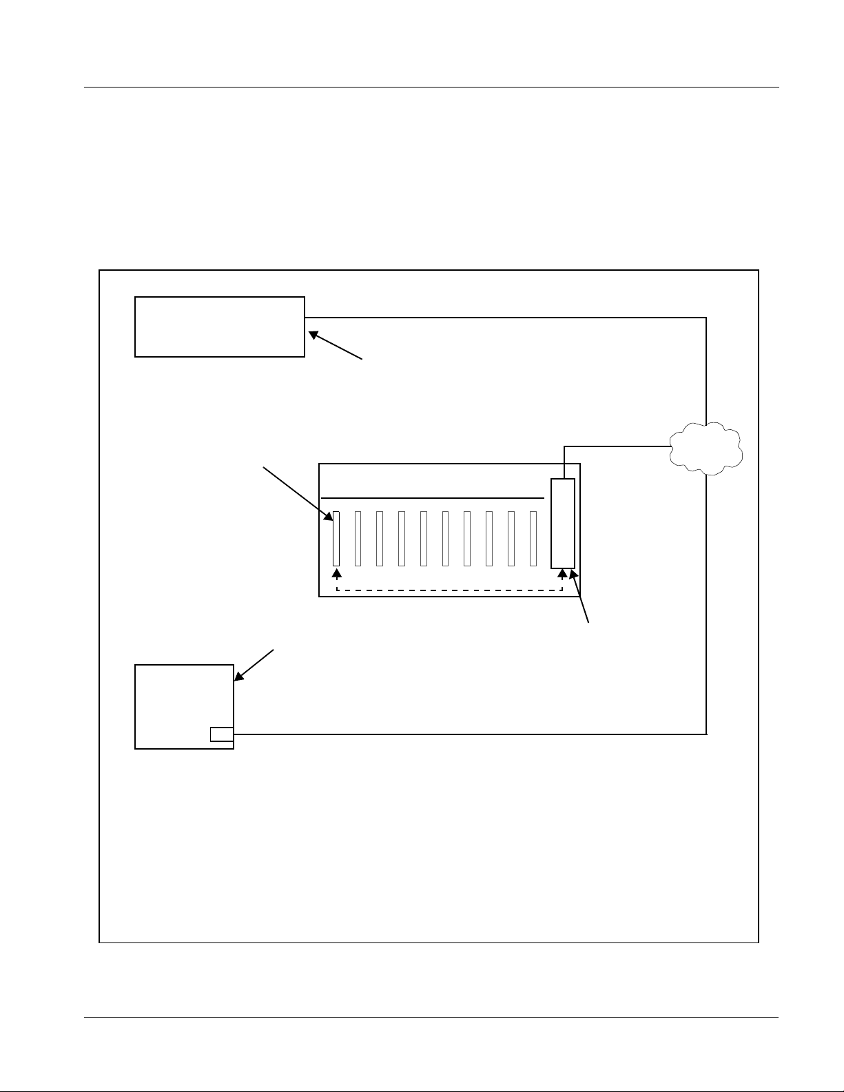
Figure 1-3 shows the user control interface options for the 9362. These
options are individually described below.
Note: All user control interfaces described here are cross-compatible and can oper-
ate together as desired. Where applicable, any control setting change made
using a particular user interface is reflected on any other connected interface.
OGCP-9000 Control Panel
OGCP-9000/CC Control Panel
Card Edge Controls
9362 card can be
controlled using built-in
card edge controls
Computer
with NIC
or
DashBoard™ Remote Control
Using a computer with
DashBoard™ installed, 9362
card can be remotely controlled
over a LAN
Remote Control Panel
Using the Control Panel,
9362 card can be remotely
controlled over a LAN
LAN
20-Slot Frame with Network Controller card
In conjunction with a frame equipped
with a Network Controller card, 9362
card can be remotely controlled over
a LAN
Note: • To communicate with DashBoard™ or a Remote Control Panel, the frame must have a Network
Controller card installed.
• DashBoard™ and the Remote Control Panels provide network control of the 9362 as shown. The
value displayed at any time on the card, or via DashBoard™ or a Control Panel is the actual value
as set on the card, with the current value displayed being the actual value as effected by the card.
Parameter changes made by any of these means are universally accepted by the card (for
example, a change made using the card edge controls will change the setting displayed on
DashBoard™ and a Control Panel; a change made using DashBoard™ will similarly change the
setting displayed on a Control Panel and the card itself).
Figure 1-3 9362 User Control Interface
9362-OM (V4.1) 9362 PRODUCT MANUAL 1-9
Page 14

1 9362 Functional Description
• Built-in Card Edge User Interface – Using the built-in card edge
controls and display, card control settings can be set us ing a front
panel menu which is described in Cha pter 3,“Operati ng Instructi ons”.
Note: Some of the 9362 functions described in this manual are available only when
using the DashBoard™, or Cobalt
Control Panel user interfaces.
• DashBoard™ User Interfa ce – Using DashBoard™, the 9362 and
other cards installed in openGear®
®
OGCP-9000 or OGCP-9000/CC Remote
1
frames such as the Cobalt®
HPF-9000 or 8321 Frame can be controlled from a computer and
monitor.
DashBoard™ allows users to view all frames on a network with
control and monitoring for all populated slots inside a frame. This
simplifies the setup and use of numerous modules in a large
installation and offers the ability to centralize monitoring. Cards
define their controllable parameters to DashBoard™, so the control
interface is always up to date.
The DashBoard™ software can be downloaded from the Cobalt
Digital Inc. website: www.cobaltdigital.com
(enter “DashBoard” in
the search window). The DashBoard™ user interface is described in
Chapter 3,“Operating Instructions”.
Note: If network remote control is to be used for the frame and the frame has not yet
been set up for remote control, Cobalt
User Guide (PN 9000RCS-RM) provides thorough information and
step-by-step instructions for setting up network remote control of COMPASS
cards using DashBoard™. (Cobalt
Remote Control Panel product manuals have complete instructions for setting
up remote control using a Remote Control Panel.)
Download a copy of this guide by clicking on the Support>Reference Docu-
ments link at www.cobaltdigital.com and then select DashBoard Remote
Control Setup Guide as a download, or contact Cobalt
Cobalt Digital Inc. (p. 1-15).
®
reference guide Remote Control
®
OGCP-9000 and OGCP-9000/CC
®
as listed in Contact
®
• Cobalt
®
OGCP-9000, OGCP-9000/CC and WinOGCP Remote
Control Panels – The OGCP-9000, OGCP-9000/CC, and WinOGCP
Remote Control Panels conveniently and intui ti vel y provi de
parameter monitor and c ontrol of the cards within the 20-slot f rame.
The remote control panels allow quick and intuitive access to
hundreds of cards in a fa ci lity, and can monitor a nd al low adjustment
of multiple p arameters at one time.
The remote control panels are totally compatible with the openGear
control software DashBoard™; any changes made with either system
are reflected on the other.
1. openGear® is a registered trademark of Ross Video Limited. DashBoard™ is a trademark of Ross
Video Limited.
1-10 9362 PRODUCT MANUAL 9362-OM (V4.1)
®
Page 15
Introduction 9362 Functional Description
9362 Rear I/O Modules
The 9362 physically interfaces to system video connections at the rear of its
frame using a Rear I/O Module.
All inputs and outputs shown in the 9362 Functional Block Diagram (Figure
1-1) enter and exit the card via the card edge backplane connector. The
Rear I/O Module breaks out the 9362 card edge connections to BNC
connectors that interface with other components and systems in the signal
chain.
These BNC connections are provided by using an optional Rear I/O Module.
The 9362 Rear I/O Modules are shown and described in Chapter 2,
“Installation and Setup”.
Audio and Video Formats Supported by the 9362
The 9362 supports all current SMPTE standard SD and HD video formats.
Table 1-1 lists and provides details regarding the audio and video formats
supported by the 9362.
Table 1-1 Supported Audio and Video Formats
Item Description/Specification
SDI Program Video Input /
Output
1080PsF 23.98; 24
1080p 23.98; 24
1080i
720p 23.98; 24; 25; 29.97; 30; 50; 59.94;
486i
575i
Embedded Audio The 9362 supports all four groups (16 channels) of embedded audio at
full 24-bit resolution in both SD (with extended data packets) and HD.
(1) All rates displayed as frame rates; interlaced (“i”) field rates are two times the rate value shown.
Raster Structure: Frame Rate:
(1)
(1)
(1)
25; 29.97; 30
60
29.97
25
9362-OM (V4.1) 9362 PRODUCT MANUAL 1-11
Page 16

1 Technical Specifications
Technical Specifications
Table 1-2 lists the technical specifications for the 9362 HD/SD-SDI Test
Signal Generator with Text Overwrite, SDI Input Frame Capture/Store, AFD/
Timecode Support, and Fail-Safe Mode card.
Table 1-2 Technical Specifications
Item Characteristic
Part number, nomenclature 9362 HD/SD-SDI Test Signal Generator with Text Overwrite, SDI
Input Frame Capture/Store, AFD/Timecode Support, and Fail-Safe
Mode
Installation/usage environment Intended for installation and usage in frame meeting openGear™
modular system definition.
Power consumption < 8 Watts maximum
Environmental:
Operating temperature:
Relative humidity (operating or storage):
32° – 104° F (0° – 40° C)
< 95%, non-condensing
Frame communication 10/100 Mbps Ethernet with Auto-MDIX.
Indicators Card edge display and indicators as follows:
• 4-character alphanumeric display
• Remote Activity LED indicator
• Input Format LED indicator
Controls Card edge switches as follows:
• Menu Enter pushbutton switch
• Menu Exit pushbutton switch
• Up/down selection toggle switch
Video Test Signal Generator Selectable output patterns:
• Black flat frame
• 75% color bars
• Sweep pattern
• User captured frame
Selectable formats/frame rates:
• 525i5994 / 625i/50
• 720p2997 / 720p25
• 1080 i5 994 / 1080i 50
Internal Tone Generators Four built-in tone generators, each configurable for 18 discrete
sine wave frequencies ranging from 50 Hz to 16 kHz.
Generator source signal level is equivalent to -20 dBu.
Resolution: 10-bit video data path
1-12 9362 PRODUCT MANUAL 9362-OM (V4.1)
Page 17

Introduction Technical Specifications
Table 1-2 Technical Specifica tions — continued
Item Characteristic
Serial Digital Video Input Data Rates Supported:
SMPTE 292 HD-SDI: 1.485 Gbps or 1.485/1.001 Gbps
SMPTE 259M-C SD-SDI: 270 Mbps
Impedance:
75 Ω terminating
Equalization (HD):
328 ft (100 m) Belden 1694A
Equalization (SD):
1000 ft (305 m) Belden 1694A
Return Loss:
> 15 dB at 5 MHz – 1.485 GHz
Post-Processor Serial Digital Video
Outputs
Pre-Processor (Reclocked) Serial Digital
Video Outputs
Number of Outputs:
Two HD/SD-SDI BNC per IEC 60169-8 Amendment 2
Impedance:
75 Ω
Return Loss:
> 15 dB at 5 MHz – 270 MHz
> 12 dB at 270 MHz – 1.485 GHz
Signal Level:
800 mV ± 10%
DC Offset:
0 V ± 50 mV
Jitter (HD ):
< 0.15 UI (all outputs)
Jitter (SD ) :
< 0.10 UI (all outputs)
Overshoot:
< 0.2% of amplitude
Number of Outputs:
Four SD-SDI BNC per IEC 60169-8 Amendment 2
Impedance:
75 Ω
9362-OM (V4.1) 9362 PRODUCT MANUAL 1-13
Page 18

1 Warranty and Service Information
Warranty and Service Information
Cobalt Digital Inc. Limited Warranty
This product is warranted to be free from defects in material and workmanship for a period of five (5)
years from the date of shipment to the original purchaser, except that 4000, 5000, 6000, 8000 series
power supplies, and Dolby
material and workmanship for a period of one (1) year.
Cobalt Digital Inc. 's (“Cobalt”) sole obligation under this warranty shall be limited to, at its option, (i)
the repair or (ii) replacement of the product, and the determinati on of whether a defect is covered under
this limited warranty shall be made at the sole discretion of Cobalt.
This limited warranty applies onl y to the original end-purchaser of the pr oduct, and is not assigna ble or
transferrable therefrom. This warranty is limited to defects i n material a nd workman shi p, and shal l not
apply to acts of God, accidents, or negligence on behalf of the purchaser, and shall be voided upon the
misuse, abuse, alteration, or modification of the product. Only Cobalt authorized factory
representatives are authorized to make repairs to the product, and any unauthorized attempt to repair
this product shall immediately void the warranty. Please contact Cobalt Technical Support for more
information.
®
modules (where applicable) are warranted to be free from defects in
To facilitate the resolutio n of warranty related issues, Co balt recommends registeri ng the product by
completing and returning a product registration form. In the event of a warrantable defect, the
purchaser shall notify Cobalt with a description of the problem, and Cobalt shall provide the purchaser
with a Return Material Authorization (“RMA”). For return, defective product s should be double boxed,
and sufficiently protected, in the original packaging, or equivalent, and shipped to the Cobalt Factory
Service Center, postage prepaid and insured for the purchase price. The purchaser should include the
RMA number, description of the problem encountered, date purchased, name of dealer purchased
from, and serial number with the shipment.
Cobalt Digital Inc. Factory Service Center
2406 E. University Avenue Office: (217) 344-1243
Urbana, IL 61802 USA Fax: (217) 344-1245
www.cobaltdigital.com Email: info@cobaltdigital.com
THIS LIMITED WARRANTY IS EXPRESSLY IN LIEU OF ALL OTHER WARRANTIES
EXPRESSED OR IMPLIED, INCLUDING THE WARRANTIES OF MERCHANTABILITY AND
FITNESS FOR A PARTICULAR PURPOSE AND OF ALL OTHER OBLIGATIONS OR
LIABILITIES ON COBALT'S PART. ANY SOFTWARE PROVIDED WITH, OR FOR USE WITH,
THE PRODUCT IS PROVIDED “AS IS.” THE BUYER OF THE PRODUCT ACK NOWLEDGES
THAT N O OTHER REPRESENTATIONS WERE MADE OR RELIED UPON WITH RESPECT TO
THE QUALITY AND FUNCTION OF THE GOODS HEREIN SOLD. COBALT PRODUCTS ARE
NOT AUTHORIZED FOR USE IN LIFE SUP PORT APPLICATIONS.
COBALT'S LIABILITY, WHETHER IN CONT RACT, TORT, WARRANTY, OR OTHERWISE, IS
LIMITED TO THE REPAIR OR REPLACEMENT, AT ITS OPTION, OF ANY DEFECTIVE
PRODUCT, AND SHALL IN NO EVENT INCLUDE SPECIAL, INDIRECT, INCIDENTAL, OR
CONSEQUENTIAL DAMAGES (INCL UDING LOST PROFITS), EVEN IF IT HAS BEEN
ADVISED OF THE POSSIBILITY OF SUCH DAMAGES.
1-14 9362 PRODUCT MANUAL 9362-OM (V4.1)
Page 19
Introduction Contact Cobalt Digital Inc.
Contact Cobalt Digital Inc.
Feel free to contact ou r th oro ugh and professional supp ort rep re sentatives for
any of the following:
• Name and address of your local dealer
• Product information and pricing
• Technical support
• Upcoming trade show i nformation
Phone: (217) 344-1243
Fax: (217) 344-1245
Web: www.cobaltdigital.com
General Information: info@cobaltdigital.com
Technical Support: support@cobaltdigital.com
9362-OM (V4.1) 9362 PRODUCT MANUAL 1-15
Page 20

This page intentionally blank
1-16 9362 PRODUCT MANUAL 9362-OM (V4.1)
Page 21

Chapter 2 Installation and Setup
Overview
This chapter contains the following information:
• Installing the 9362 Into a Frame Slot (p. 2-1)
• Installing a Rear I/O Module (p. 2-3)
• Setting Up 9362 Network Remote Control (p. 2-5)
Installing the 9362 Into a Frame Slot
Chapter 2
CAUTION
CAUTION
Heat and power distribution requirements within a frame may dictate specific
slot placement of cards. Cards with many heat-producing compon ents should
be arranged to avoid areas of excess heat build-up, particularly in frames
using only convection cooling.
CAUTION
This device contains semiconductor devices which are
susceptible to serious damage from Electrostatic
Discharge (ESD). ESD damage may not be immediately
apparent and can affect the long-term reliability of the
device.
Avoid handling circuit boards in high static environments
such as carpeted areas, and when wearing synthetic fiber
clothing. Always use proper ESD handling precautions
and equipment when working on circuit boards and
related equipment.
9362-OM (V4. 1) 9362 PRODUCT MANUAL 2-1
Page 22

2 Installing the 9362 Into a Frame Slot
Note: If installing the 9362 in a slot with no rear I/O module, a Rear I/O Module
is required before cabling can be connected. Refer to Installing a Rear I/O
Module (p. 2-3) for rear I/O module installation procedure.
CAUTION
If required, make certain Rear I/O Module(s) is installed before installing the
9362 into the frame slot. Damage to card and/or Rear I/O Module can occur if
module installation is attempted with card already installed in slot.
Note: Check the packaging in which the 9362 was shipped for any extra items such
as a Rear I/O Module connection label. In some cases, this label is shipped
with the card and to be installed on the Rear I/O connector bank corresponding to the slot location of the card.
Install the 9362 into a frame slot as follows:
1. Determine the slot in which the 9362 is to be installed.
2. Open the frame front access panel.
3. While holding the card by the card edges, align the card such that the
plastic ejector tab is on the bottom.
4. Align the card with the top and bottom guides of the slot in which the
card is being installed.
5. Gradually slide the card into the slot. When re sistance is noticed, gently
continue pushing the card until its rear printed circuit edge terminals
engage fully into the rear I/O module mating connector.
CAUTION
If card resists fully engaging in rear I/O module mating connector, check for
alignment and proper insertion in slot tracks. Damage to card and/or rear I/O
module may occur if improper card insertion is attempted.
Verify that the card is fully engaged in rear I/O module mating connector.
6.
7. Close the frame front access panel.
8. Connect the input and output cables as shown in Figure 2-1.
9. Repeat steps 1 through 8 for other 9362 cards.
Note: The 9362 BNC inputs are internally 75-ohm terminated. It is not necessary to
terminate unused BNC inputs or outputs.
Note: To remove a card, press down on the ejector tab to unseat the card from the
rear I/O module mating connector. Evenly draw the card from its slot.
10. If network rem ote control is to be used for the fram e and the frame has
not yet been set up for remote control, perform setup in accordance with
Setting Up 9362 Network Remote Control (p. 2-5).
2-2 9362 PRODUCT MANUAL 9362-OM (V4.1)
Page 23

Installation and Setup Installing a Rear I/O Module
Note: If installing a card in a frame already equipped for, and connected to
DashBoard™, no network setup is required for the card. The card will be discovered by DashBoard™ and be ready for use.
Rear module RM20-9362-A Rear I/O Module use the
connector arrangements shown to the left and described
below.
• HD/SD-SDI coaxial input (SDI IN)
• Four HD/SD-SDI reclocked input copies (RCK OUT 1 thru
RCK OUT 4)
• Four buffered SDI coaxial outputs (SDI OUT 1 thru
SDI OUT 4)
Connect cabling as shown. Unused connectors do not
require external termination.
RM-9362-A.PNG
Viewed from the rear, the right
column of BNC connectors
accommodates the right-most card,
with the left column accommodating
the adjacent card to the left.
In this example with two 9362 cards in
slots 1 and 2, the right column serves
9362, slot 1 and the left column
serves 9362, slot 2.
Figure 2-1 9362 Rear I/O Module Connections
Installing a Rear I/O Module
Where a maximum of five BNC connections can suit
particular I/O requirements, a “split” Rear I/O Module offers
maximum card density within the frame by accommodating
two cards using a module occupying no more area than a
standard module. The RM20-9362-A/S shown here provides
each of the following connections for two 9263 cards as
described below.
• HD/SD-SDI coaxial input (SD I IN )
• Two HD/SD-SDI reclocked input copy (RCK OUT 1) and
RCK OUT 2)
• Two buffered SDI coaxial outputs (SDI OUT 1 and
SDI OUT 2)
RM-9362-AS.PNG
Note: This procedure is applicable only if a Rear I/O Module is not currently
installed in the slot where the 9362 is to be installed.
If installing the 9362 in a slot already equipped with a suitable I/O module,
omit this procedure.
9362-OM (V4.1) 9362 PRODUCT MANUAL 2-3
Page 24

2 Installing a Rear I/O Module
Install a Rear I/O Module as follows:
1. On the frame, determine the slot in which the 9362 is to be installed.
2. In the mounting area corresponding to the slot location, install
Rear I/O Module as shown in Figure 2-2.
Align and engage mounting tab on Rear
I/O Module with the module seating slot
1
on rear of frame chassis.
DSCN3483A.JPG
Hold top of Rear I/O Module flush against
frame chassis and start the captive screw.
2
Lightly tighten captive screw.
DSCN3487A.JPG
Figure 2-2 Rear I/O Module Installation
2-4 9362 PRODUCT MANUAL 9362-OM (V4.1)
Page 25

Installation and Setup Setting Up 9362 Network Remote Control
Setting Up 9362 Network Remote Control
Perform remote control setup in accordance with Cobalt® reference guide
“Remote Control User Guide” (PN 9000RCS-RM).
Note: • If network rem ote control is to be used for the frame and the frame has not
yet been set up for remote control, Cobalt
Control User Guide (PN 9000RCS-RM) provides thorough information and
step-by-step instructions for setting up network remote control of
COMPASS™ cards u sing Das hB oard ™. (Cobalt
OGCP-9000/CC Remote Control Panel product manuals have complete
instructions for setting up remote control using a Remote Control Panel.)
Download a copy of this guide by clicking on the
Support>Reference Documents link at www.cobaltdigital.com and then
select DashBoard Remote Control Setup Guide as a download, or contact
®
Cobalt
• If installing a card in a frame already equipped for, and connected to
DashBoard™, no network setup is required for the card. The card will be discovered by DashBoard™ and be ready for use.
as listed in Contact Cobalt Digital Inc. (p. 1-15).
®
reference guide Remote
®
OGCP-9000 and
9362-OM (V4.1) 9362 PRODUCT MANUAL 2-5
Page 26

This page intentionally blank
2-6 9362 PRODUCT MANUAL 9362-OM (V4.1)
Page 27

Overview
Chapter 3
Chapter 3 Operating Instructions
This chapter contains the following information:
If you are already familiar
with using DashBoard or a
Cobalt Remote Control
Panel to control Cobalt
cards, please skip to 9362
Function Submenu Li st and
Descriptions (p. 3-8).
• Control and Display Descriptions (p. 3-1)
• Accessing the 9362 Card via Remote Control (p. 3-3)
• Checking 9362 Card Information (p. 3-5)
• Ancillary Data Line Number Locations and Ranges (p. 3-7)
• 9362 Function Submenu List and Descriptions (p. 3-8)
• Troubleshooting (p. 3-19)
Control and Display Descriptions
This secti on describes the user interface controls, indicators, and displays for
using the 9362 card. The 9362 function s can be acces sed and contr olle d using
any of the user interfaces described here.
The format in which the 9362 functional controls, indicators, and displays
appear and are used varies depending on the user interface being used.
Regardless of the user interface being used, access to the 9362 functions (and
the controls, ind icato rs, an d disp lays r elat ed to a particul ar f uncti on) fo llows a
general arrangement of Function Submenus under which related controls can
be accessed (as described in Function Submenu/Parameter Submenu
Overview below).
Note: DashBoard™ and the Remote Control Panel provide greatly simplified user
interfaces as compared to using the card edge controls. For this reason, it is
strongly recommended that DashBoard™ or a Remote Control Panel be
used for all card applications other than the most basic cases. Card edge
control codes are not included in this manual. If card-edge control is to be
used, obtain a copy of “Manual Supplement – Card-Edge Control Reference
Master List and Instructions for Using Compass
Codes” (989CEC-MS.pdf) at www.cobaltdigital.com>Support>>Reference
Documents.
9362-OM (V4. 1) 9362 PRODUCT MANUAL 3-1
®
Card-edge (Local) Control
Page 28

3 Control and Display Descriptions
Note: When a setting is changed, settings displayed on DashBoard™ (or a Remote
Control Panel) are the settings as effected by the 9362 card itself and
reported back to the remote control; the value displayed at any time is the
actual value as set on the card.
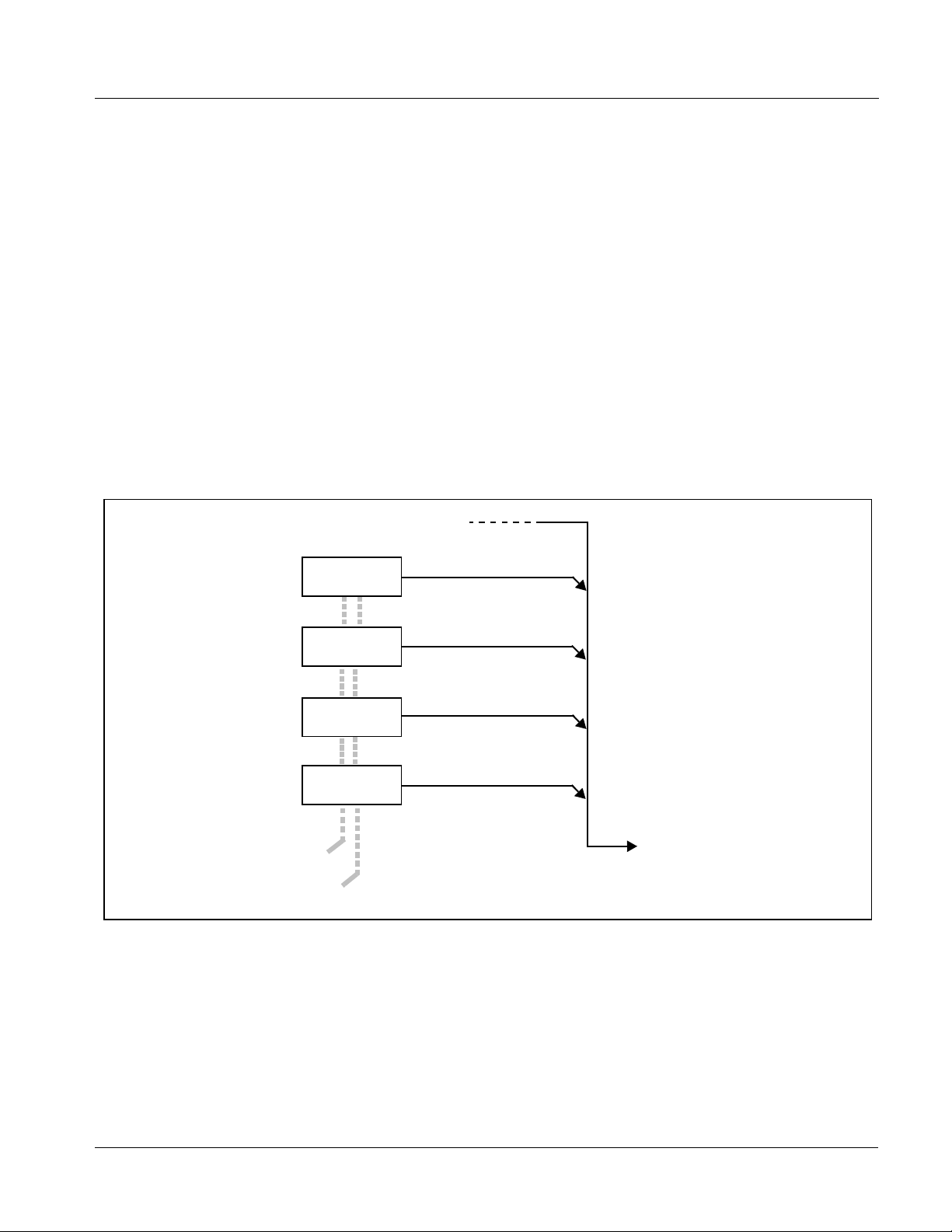
Function Submenu/Parameter Submenu Overview
The functions and related pa rameters avai lable on the 9362 car d are organ ized
into function submenus, which consist of parameter groups as shown below.
Figure 3-1 shows how the 9362 card an d its submenus ar e orga nized, and also
provides an overview of how navig ation is performed be tween cards, func tion
submenus, and parameters.
If using DashBoard™ or a Remote Control Panel, the
desired 9362 card is first selected.
9362
Submenu a Submenu b
Individual Parameters
Each submenu consists of groups of parameters
related to the function submenu. Using the “Test
Signal Generator” function submenu example, the
individual parameters for this function consist of
various TSG selections such as output formats,
patterns, and so on.
Figure 3-1 Function Submenu/Parameter Submenu Overvie w
• • •
The desired function submenu is next
selected.
Function Submenus consist of parameter
groups related to a particular 9362 card
function (for example, “Test Signal
Generator”).
Submenu z
3-2 9362 PRODUCT MANUAL 9362-OM (V4.1)
Page 29

Operating Instructions Accessing the 9362 Card via Remote Control
DashBoard™ User Interface
(See Figure 3-2.) Th e 9362 fu nction submenus are or gani zed i n DashBoa rd™
using tabs. When a tab is selected, each parametric control or selection list
item associated with the function is displayed. Scalar (numeric) parametric
values can then be adjusted as desired using the GUI slider controls. Items in
a list can then be selected using GUI drop-down lists.
DashBoard Tabs
Figure 3-2 Typical DashBoard Tabs and Controls
Typical Selection
List
Accessing the 9362 Card via Remote Control
Access the 9362 card using DashBoard™ or Cobalt® Remote Control Panel
as described below.
Accessing the 9362 Card Using DashBoard™
1. On the computer connected to the frame LAN, open DashBoard™.
2. As shown be low, in the left side Basic View Tree locate the Network
Controller Card associated with the frame containing the 9362 card to be
accessed (in this example, “MFC-8320-N SN: 00108053”).
9362-OM (V4.1) 9362 PRODUCT MANUAL 3-3
Page 30

3 Accessing the 9362 Card via Remote Control
DB_ACCESS1.PNG
3. As shown below, expand the tree to access the cards within the frame.
Click on the card to be accessed (in this example,
.
“Slot 6: TSG-9362”).
9362_DB_ACCESS2A.PNG
As shown on the next page, when the card is a ccess ed a Das hBoard ™ its
function submenu screen showing tabs for each function is displayed.
(The particular submenu screen displayed is the previously displayed
screen from the last time the card was accessed by DashBoard™).
3-4 9362 PRODUCT MANUAL 9362-OM (V4.1)
Page 31

Operating Instructions Checking 9362 Card Information
Card Access/Navigation
Tree Pane
Card Info
Pane
Card Function Submenu
and Controls Pane
Checking 9362 Card Information
The operating st atus and s oftwar e ver sion the 9 362 car d can be chec ked us ing
DashBoard™ or the card edge control user interface. Figure 3-3 shows and
describes the 9362 card i nformati on screen usi ng DashBoard™ a nd acces sing
card information using the card edg e control user interfac e.
Note: Proper operating status in DashBoard™ is denoted by green icons for the sta-
tus indicators shown in Figure 3-3. Yellow or red icons respectively indicate
an alert or failure condition. Refer to Troubleshooting (p. 3-19) for corrective
action.
9362_DB_ACCESS3A3.PNG
9362-OM (V4.1) 9362 PRODUCT MANUAL 3-5
Page 32

3 Checking 9362 Card Information
The Tree View shows the cards seen by DashBoard™.
In this example, Frame A is hosting a 9362 card in slot 6.
Software Version and
Software Build Number
Refer to these numbers to check that documentation (such as this
manual) matches the card’s Software Release Number and
Software Build Number. Use these numbers also when
communicating to Cobalt
Power Consumption and Temperature Displays
This display shows the power consumed by the 9362
for both the +12V and -7.5V rails, as well as key device
temperatures.
Status Displays
These displays show the status the signal being received by
the 9362. Green Settings icon shows that any changes made
on DashBoard™ are sucessfully saved on the card’s memory.
®
regarding this card.
9362_CARD_INFO2.PNG
Figure 3-3 9362 Card Info Utility
3-6 9362 PRODUCT MANUAL 9362-OM (V4.1)
Page 33

Operating Instructions Ancillary Data Line Number Locations and Ranges
Ancillary Data Line Number Locations and Ranges
Table 3-1 lists typical default output video VANC line number locations for
various ancillary data items that may be passed or handled by the card.
Table 3-1 Typical Ancillary Data Line Number Locations/Ranges
Default Line No. / Range
Item
SD HD
AFD 12 (Note 2) 9 (Note 2)
ATC _ VITC 13 (Note 2) 9/8 (Note 2)
ATC_LTC — 10 (Note 2)
®
Dolby
Metadata 13 (Note 2) 13 (Note 2)
SDI VITC Waveform 14/16 (Note 2) —
Closed Captioning 21 (locked) 10 (Note 2)
Notes:
1. The card does not check for conflicts on a given line number. Make certain the selected line is available
and carrying no other data.
2. While range indicated by drop-down list on GUI may allow a particular range of choices, the ac tual ran ge
is automatically c lampe d (limi ted) to cer tain ranges to pre vent in adver tent confli ct with activ e pict ure a rea
depending on video format. Limiting ranges for various output formats are as follows:
Format Line No. Limiting Format Line No. Limiting Format Line No. Limiting
525i 12-19 720p 9-25 1080p 9-41
625i 9-22 1080i 9-20
Because line number allocation is not standardized for all ancillary items,
consideration should be given to all items when performing set-ups. Figure
3-4 shows an example of improper and corrected VANC allocation within an
HD-SDI stream.
ATC_VITC = 9/8
CC = 10
Dolby Meta data = 13
Card 1
ATC_VITC = 9/ 8
CC = 10
Dolby Metadata = 13
Card 1
AFD Insertion
attempted usin g
VANC line 9
(default)
AFD Insertion
corrected to us e
VANC line 18
ATC_VITC = 9/8
AFD = 9
CC = 10
Dolby Meta data = 13
Card n
ATC_VITC = 9/8
CC = 10
Dolby Metadata = 13
AFD = 18
Card n
Conflict between
ATC_VITC and AFD both
on VANC line 9
Conflict between
ATC_VITC on line 9/8 and
AFD (now on line 18)
resolved
Figure 3-4 Example VANC Line Number Allocation Conflict and Resolution
9362-OM (V4.1) 9362 PRODUCT MANUAL 3-7
Page 34

3 9362 Function Submenu List and Descriptions
9362 Function Submenu List and Descriptions
Table 3-2 individually lists and describes each 9362 function submenu “tab”
and its rela ted list selections, controls, and parameters. Where helpful,
examples showing usage of a function are also provided. Table 3-2 is
primarily based upon using DashBoard™ to access each function and its
corresponding submenus and parameters.
Note: All numeric (scalar) parameters displayed on DashBoard™ can be changed
using the slider controls, arrows, or by numeric keypad entry in the corresponding numeric field. (When using numeric keypad entry, add a return after
the entry to commit the entry.)
On DashBoard™ itself and in Table 3-2, the function submenu items are
organized using tabs as shown below.
The table below provides a quick-reference to the page numbers where each
function submenu item can be found.
Function Submenu Item Page Function Submenu Item Page
AFD
Embedded Audio Group 1/2 and
3/4 TSG Audio Controls
Test Signal Generator
3-9
3-10
3-12
Timecode Generator
Tone Generator
Presets
3-14
3-16
3-16
3-8 9362 PRODUCT MANUAL 9362-OM (V4.1)
Page 35

Operating Instructions 9362 Function Submenu List and Descriptions
Table 3-2 9362 Function Submenu List
Allows assignment of AFD (Active Format Description)
codes to the SDI output video.
Note: This function only marks the SDI output with an AFD code. Actual AFD processing must be performed by a downstream
card or system that recognizes an AFD code assigned here.
• Incoming AFD Displays incoming AFD setting as follows:
• If AFD code is present, one of the 1 1, four-bit AFD codes is displayed (as
shown in the example to the left). Also displayed is the VANC line
number of the incoming AFD code.
• If no AFD setting is present in the video signal, No AFD Present is
displayed.
AFD
• Output Mode Drop-down selection determines action to take in presence or absence of
existing AFD code on input video.
Note: Outputted AFD generated by card is present for both input video
and TSG output streams.
AFD
• Output Code Drop-down list assigns desired AFD to output SDI.
4:3 Coded Frame
AFD Code
•
•
•
16:9 Coded Frame
AFD Code
1: AFD codes numbering and definitions conform to SMPTE 2016-1-2007.
2: Image Prot ecte d impl ies pictu re cont ent that must not be cropped by
(1)
Description AFD Code
– No code present 1001 Full frame
0000 Undefined 1010 16:9 (center)
0010 Box 16:9 (top) 1011 14:9 (center)
0011 Box 14:9 (top) 1101 4:3 (with alternate
0100 Box > 16:9 (center) 1110 16:9 (with alternate
1000 Full frame 1111 16:9 (with alternate
(1)
Description AFD Code
– No code present 1001 4:3 (center)
0000 Undefined 1010 16:9 (image
0010 Full frame 1011 14:9 (center)
0011 4:3 (center) 1101 4:3 (with alternate
0100 Box > 16:9 (center) 1110 16:9 (with alternate
1000 Full frame 1111 16:9 (with alternate
conversion processes or display devices. Alternate center formats may
have protected center areas, with areas outside of the protected area not
containing mandatory content.
(1)
(1)
Description
14:9 center)
14:9 center)
4:3 center)
Description
protected)
14:9 center)
14:9 center)
4:3 center)
(2)
(2)
(2)
(2)
(2)
• Output Line Allows selecting the line location of the AFD data within the video signal
Ancillary Data space. (Range is 9 thru 41; default is line #12.)
Note: • Although the output line drop-down will allow any choice within the
9 thru 41 range, the actual range is automatically clamped (limited)
to certain ranges to prevent inadvertent conflict with active picture
area depending on video format. See Ancillary Data Line Number
Locations and Ranges (p. 3-7) for more information.
• The card does not check for conflicts on a given line number.
Make certain the selected line is available and carrying no other
data.
9362-OM (V4.1) 9362 PRODUCT MANUAL 3-9
Page 36
3 9362 Function Submenu List and Descriptions
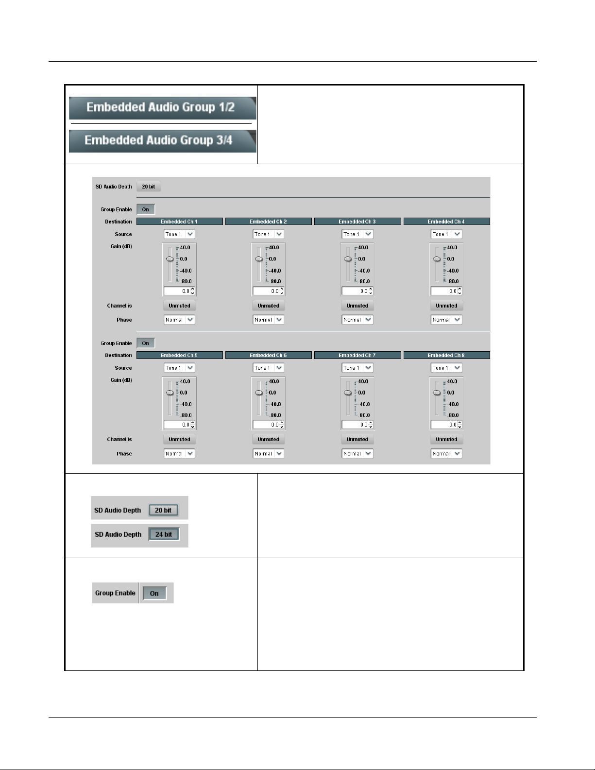
Table 3-2 9362 Function Submenu List — continued
Selects the TSG audio source for each embedded
audio channel 1 thru 16 (Embedded Audio Groups 1/2
and 3/4) to be used when TSG is active.
Embedded Audio Group 1/2 and 3/4 TSG Aud io Controls
• SD Audio Depth Allows option of using 24-bit audio data structure per SMPTE 272M,
• Group Enable When enabled (On), enables the embedding of the corresponding
§3.10.
Note: • If 24-bit depth is desired, make certain downstream equipment is
compatible with 24-bit SD audio data.
• Depth control setting applied here affects both Embedded Audio
Group 1/2 and 3/4.
embedded audio group (Embedded Audio Group 1 thru 4).
Group Enable buttons correspondingly enable or disable Embedded
Audio Group 1 thru Embedded Audio Group 4.
Disabling a group removes the entire group of embedded audio channels
while preserving the settings of the channels belonging to the group.
Note: These controls are only to be used with TSG audio, and only while
TSG is invoked. Manipulating these controls while the card is
passing input video will result in severe embedded audio
corruption.
3-10 9362 PRODUCT MANUAL 9362-OM (V4.1)
Page 37

Operating Instructions 9362 Function Submenu List and Descriptions
Table 3-2 9362 Function Submenu List — continued
(continued)
Note: • When input video is active on output, embedded channel routing is per assignment in program SDI video. Source,
destination, and other controls here only control TSG audio (overwrite using card tone generators or silence).
• Embedded Ch 2 thru Embedded Ch 8, and Embedded Ch 9 thru Embedded Ch 16 have controls identical to the
Source, Gain, Mute, and Phase controls described here for Embedded Ch 1. Therefore, only the Embedded Ch 1
controls are shown here.
• For each channel, its source and destination should be considered and appropriately set. Unused destination channels
should be set to the Silence selection.
• Tone Generator 1 thru 4 as Source Tone Ge ne r a tor 1 thru Tone Generator 4 range in Source drop-down list
• Silence (Mute) as Source Silence selection in Source drop-down list mutes the selected destination
enables one of four tone generators (Tone 1 thru Tone 4) to be the source
for the selected destination Embedded Audio Group channel.
(In this example, Tone 1 (tone generator 1) is the source for destination
Embedded Ch 1)
Note: Tone generator frequencies can be independently set for the four
tone generator sources.
Refer to Tone Ge ne r a tor function description on page 3-16 for
more information.
Embedded Audio Group channel. Use this setting for unused
destination channels.
(In this example, silence (muting) is applied to Embedded Ch 1)
• Gain (dB) Control Adjusts relative gain (in dB) applied to the corresponding destination
• Mute Control Allows pushbutton On/Off channel muting while saving all other settings.
• Phase Control Selects between Normal and Invert phase (relative to source original
9362-OM (V4.1) 9362 PRODUCT MANUAL 3-11
Embedded Audio Group channel.
(-80 to +40 dB range in 0.1 dB steps; unity = 0.0 dB)
phase) for the destination Embedded Audio Group channel.
Page 38

3 9362 Function Submenu List and Descriptions
Table 3-2 9362 Function Submenu List — continued
Provides video Test Signal Generator pattern, output,
failover, and frame sync controls.
• Video Output Mode Video Output Mode selects between automatic failover or manually
invoked TSG output.
• W hen set to Always Test Signal, card outputs selected TSG output
regardless of presence of valid SDI input.
• W hen set to Input Video If Present Otherwise Test Signal, card is set
for automatic failover. Valid SDI passes unaffected, with output switching
to selected TSG output only in the event of input SDI loss of signal.
Test Signal Generator
• Generator Output Format Sets TSG output format (as shown from choices to the left) when TSG is
invoked either automatically of manually.
Note: Selection only applies to TSG SDI output and has no relationship
with input video format. It is recommended in normal operation that
this control be set to match that of the normal program video format
being handled by the card.
SD: Convert To
• Superimposed Text Text entry box for entering text (using keyboard) that is superimposed
• Timing Reference Sets output timing to use internal clock timing source, or either of two
over center of TSG image. Press keyboard Enter key to commit text entry.
Note: Maximum character entry is 20 characters.
frame-supplied framesync sources.
• Internal setting uses card internal (self) clocking. The Internal
setting allows the card to output TSG patterns without any external
signal feeds to the card.
• T he Reference 1 and Reference 2 settings allows the card output
to frame sync with an external reference.
Note: Reference 1 and/or Reference 2 settings apply frame sync to
either input video or TSG output.
Note: • Reference 1 a nd/or Reference 2 settings apply frame sync to
either input video or TSG output.
• This card is not specified for use of 720p tri-level frame sync with
525i5994 program video input. Do not use 720p reference with
525i5994 program video input.
3-12 9362 PRODUCT MANUAL 9362-OM (V4.1)
Page 39

Operating Instructions 9362 Function Submenu List and Descriptions
Table 3-2 9362 Function Submenu List — continued
(continued)
• Pattern
• Capture Controls
• Vertical Delay Control When Reference 1 or Reference 2 framesync is enabled, sets vertical
Sets TSG output pattern (as shown from choices to the left) when TSG is
invoked either automatically of manually.
For User Captured selection, first capture an input video frame as
follows:
Note: • Output video freeze and momentary interruption occurs when
an image is captured. Do not perform this step using live OTA
video.
• HD captures take longer than SD captures to fully acquire
frame.
1. Set Video Output Mode to Input Video.
2. Roll video containing image to be captured.
3. When segment containing desired image appears, set Freeze to
Capture to On.
4. Click/confirm Capture User Pattern: Confirm. Wait until the Progress
bar indicates 100%. Image is now captured.
5. When capture is 100%, set Freeze for Capture to Off; the live input
video resu mes.
Note: User captured frame displays properly only when Generator
Output Format setting matches format of captured frame; the
capture function does not cross-convert formats.
delay (in number of lines of output video/format) between the output
video and the frame sync reference.
(Range is -1124 thru 1124 lines.)
Note: Lines refer to lines in the output video format, and not to the
reference format.
• Horizontal Delay Control When Reference 1 or Reference 2 framesync is enabled, sets (in µsec of
output video timing) horizontal delay between the output video and the
frame sync reference. (Range is -64.000 thru 64.000 µsec)
Note: When an external framesync reference is used, the card will not
produce a framesync reset until the variance between framesync
reference and output video exceeds ± 2 clock periods. Therefore, a
framesync reset will not result if offsets within this window are
applied. To apply an offset/framesync reset within this window, first
apply a relatively large offset, then apply the target smaller offset.
Example: T o apply a 1-period offset, first apply a 10-period positive
offset and then apply a 9-period negative offset. This results in the
target 1-period offset being applied to the output video.
9362-OM (V4.1) 9362 PRODUCT MANUAL 3-13
Page 40

3 9362 Function Submenu List and Descriptions
Table 3-2 9362 Function Submenu List — continued
Provides configurable timecode data for TSG output in
various formats supporting all available TSG output SDI
Timecode Generator
formats.
• VITC Waveform Output Line When an SD TSG output is selected, selects the VITC1 and VITC2 line
• SD VITC Waveform Insertion Control Enables or disables VITC waveform timecode insertion into the SD-SDI
• SD ATC Insertion Control For SD TSG output, enables or disables SD ATC_VITC timecode
• HD ATC_VITC Insertion Control For HD TSG output, enables or disables ATC_VITC timecode insertion
numbers (6 thru 22) where the VITC data is inserted.
Note: • Although the output line drop-down will allow any choice within the
6 thru 22 range, the actual range is automatically clamped
(limited) to certain ranges to prevent inadvertent conflict with
active picture area depending on video format. See Ancillary Data
Line Number Locations and Ranges (p. 3-7) for more information.
• T he card does not check for conflicts on a given line number.
Make certain the selected line is available and carrying no other
data.
• If only one output line is to be used, set both controls for the same
line number.
output stream.
insertion into the video stream.
Note: SD ATC_VITC is locked to line 12. The card does not check for
conflicts on a given line number. Make certain this line i s available if
SD ATC_VITC is to be used. See Ancillary Data Line Number
Locations and Ranges (p. 3-7) for more information.
into the video stream.
• HD ATC_ VITC Line Insertion Controls For HD ATC_VITC TSG timecode output, selects the line number for
• HD ATC_LTC Insertion Control For HD TSG output, enables or disables AT C_L TC timecode insertion into
ATC_VITC1 and ATC_VITC2.
Note: • Although the output line drop-down will allow any choice within the
8 thru 20 range, the actual range is automatically clamped
(limited) to certain ranges to prevent inadvertent conflict with
active picture area depending on video format. See Ancillary Data
Line Number Locations and Ranges (p. 3-7) for more information.
• The card does not check for conflicts on a given line number.
Make certain the selected line is available and carrying no other
data.
• If only one output line is to be used, set both controls for the same
line number.
the video stream.
3-14 9362 PRODUCT MANUAL 9362-OM (V4.1)
Page 41

Operating Instructions 9362 Function Submenu List and Descriptions
Table 3-2 9362 Function Submenu List — continued
(continued)
• HD ATC_LTC Line Insertion Control For HD TSG timecode output, selects the line number for ATC_LTC
• ATC_VITC Legacy Support Control When enabled, accommodates equipment requiring ATC_VITC packet in
• Timecode Start Selection Selection lists for entering initial (starting) timecode in:
timecode data.
Note: • Although the output line drop-down will allow any choice within the
both fields as a “field 1” packet (non-toggling).
Note: Non-toggling VITC1 and VITC2 packets do not conform to
Note: Although frame range drop-down shows full control range, frame
9 thru 20 range, the actual range is automatically clamped
(limited) to certain ranges to prevent inadvertent conflict with
active picture area depending on video format. See Ancillary
Data Line Number Locations and Ranges (p. 3-7) for more
information.
• The card does not check for conflicts on a given line number.
Make certain the selected line is available and carrying no other
data.
SMPTE 12M-2-2008 preferences. As such, ATC_VITC Legacy
Support should be enabled only if required by downstream
equipment.
• Hours: 0 to 24 hours
• Minutes: 0 to 59 minutes
• Seconds: 0 to 59 seconds
• Frames: 0 to 59 frames
range is clamped as appropriate for TSG output format selected
using Test Signal Generator tab.
Reset and start a count as follows:
1. Enable desired timecode format as described on previous pages.
2. Enter desired start count using drop-down lists shown to the left.
3. Click Apply Values: Confirm. The pop-up shown below appears
showing the count is ready to be initialized to the entered values.
4. T o reset and start the count at entered value, click Yes. At this instance,
entered count commences and increments accordingly.
Note: • Timecode entered with this function is applied to TSG output
only; program material timecode when outputted by the card is
not affected by this function.
• When count is initiated, count remains in effect regardless of
whether TSG output is invoked. If TSG output is invoked at a
later time, the count reflects the running count, as initiated per
the preceding Confirm action described above.
9362-OM (V4.1) 9362 PRODUCT MANUAL 3-15
Page 42

3 9362 Function Submenu List and Descriptions
Table 3-2 9362 Function Submenu List — continued
(continued)
• Output Stat us Dis play Displays the current timecode being generated as follows:
• Output status OK and enabled for output using an insertion control
(described below).
• Timecode disabled by no insertion selected on an insertion control
(described below).
Note: • Least significant 0 or 1 digit marks odd or even field for
interlaced-format outputs. For progressive formats, digit toggles to
mark each frame (i.e., frames 0 thru 59 are marked as 0.0 thru
29.1).
• Status display may not indicate running real time updating due to
network delays on DashBoard communications.
Sets the test tone frequency for each of four tone
Tone Generator
generators (Tone Generator 1 thru 4).
• Frequency Selection Lists Selects the frequency for each of the four tone generators. 18 discrete
•
•
•
sine wave frequencies are available, ranging from 50 Hz to 16 kHz
(default frequency is 1.0 kHz).
Note: Unity-gain signal level is equivalent to -20 dBu.
Allows up to 16 card user set tin gs co nfi gur at ion pres et s
to be saved in a Preset and then recalled (loaded) as
Presets
desired. All current settings (including list selections
and scalar (numeric) control settings are saved when a
Preset Save is invoked.
The Preset Name field and Preset Save button
allow custom user setting configurations to be
labeled and saved to a Preset for future use.
The Preset Load button and the Selected Preset
drop-down list allow saved presets to be selected
and loaded as desired. When a preset is loaded, it
immediately becomes active with all user settings
now automatically set as directed by the preset.
Saved presets can be uploaded to a computer for
use with other same-model COMPASS™ cards.
Each of the items to the left are described in detail on
the following pages.
3-16 9362 PRODUCT MANUAL 9362-OM (V4.1)
Page 43

Operating Instructions 9362 Function Submenu List and Descriptions
Table 3-2 9362 Function Submenu List — continued
(continued)
• Preset Save and Load • Preset Save stores all current card control settings to the currently
• Selected Preset Selected Preset 1 thru Selected Preset 16 range in drop-down list
•
•
•
• Preset Name With one of 16 presets selected, provides for entry of custom name for the
selected preset.
(For example, if Preset 1 is selected in the Selected Preset drop-down
list, clicking and confirming Preset Save will then save all current card
control settings to Preset 1)
• Preset Load loads (applies) all card control settings defined by
whatever preset (Preset 1 thru Preset 16) is currently selected in the
Selected Preset drop-down list.
(For example, if Preset 3 is selected in the Selected Preset drop-down
list, clicking and confirming Preset Load will then apply all card control
settings defined in Preset 3)
The above buttons have a Confirm? pop-up that appears, requesting
confirmation.
Note: Applying a change to a preset using the buttons described above
rewrites the previous preset contents with the invoked contents.
Make certain change is desired before confirming preset change.
selects one of 16 stored presets as ready for Save (being written to) or for
Load (being applied to the card).
Note: The preset names shown to the left are the default (unnamed)
preset names. All 16 presets in this case are loaded identically with
the factory default settings.
preset (as shown in example below).
Entering text in Preset
Name field (in this
example, “RCVR21”)
applies custom name to
selected Preset (in this
example, Preset 2)
Note: • Preset name can be seven ASCII characters maximum.
• The Preset ID number does not need to be entered; it is
added automatically.
• Card Name Text entry field provides for optional entry of card name, function, etc. (as
• Reset Current Preset • Reset Current Preset resets all parameters (including preset custom
shown in this example).
Note: Card name can be 31 ASCII characters maximum.
name entered) of the currently selected Preset (as displayed in the
Selected Preset field) to factory default settings.
The above button has a Confirm? pop-up that appears, requesting
confirmation.
9362-OM (V4.1) 9362 PRODUCT MANUAL 3-17
Page 44

3 9362 Function Submenu List and Descriptions
Table 3-2 9362 Function Submenu List — continued
(continued)
• Download Presets Download Presets allows all 16 presets to be stored to a specified location
Download a presets file to a computer on the card’s DashBoard network to save presets. Preset files stored on a computer can
then be uploaded back to the card.
Note also that a presets file can also be uploaded to other same-model COMPASS
using a single card can be easily applied to other same-model cards without repeating the setup work on the other cards.
Download (save) card presets to a
network computer by clicking
Download
Presets – Save
at the bottom of
the Presets
page.
Browse to a desired
save location (in
this example, My
Documents\Cobalt
Presets).
The file can then be
renamed if desired
(RCVR21 Presets
in this example)
before saving.
on a network computer for use with other same-model COMPASS™
cards.
®
Refer to Cobalt
9000RCS-RM) for instructions on using the Download Presets function.
reference guide “Remote Control User Guide” (PN
®
cards. In this manner, presets built up
Upload (open) card presets from a network
computer by clicking Upload
at the bottom of
DashBoard.
Browse to the location
where the file was saved
on the computer or
drive (in this example,
My Documents\Cobalt
Presets).
Select the desired file
and click Open to load
the file to the card.
To upload presets
saved from one card
to another same-model card, simply click Upload on the
other same-model card’s DashBoard page and repeat the
same steps here.
Note: • Preset transfer between card download and file
upload is on a group basis (i.e., individual presets
cannot be downloaded or uploaded separately).
• After uploading a presets file, engagement of a
desired preset is only assured by pressing the Preset
Load button for a desired preset.
3-18 9362 PRODUCT MANUAL 9362-OM (V4.1)
Page 45

Operating Instructions Troubleshooting
Troubleshooting
This section provides general troubleshooting information and specific
symptom/c orrective action for the 9362 card and its remote control interface.
The 9362 card requires no periodic maintenance in its normal operation; if
any error indication (as described in this section) occurs, use this section to
correct the condition.
Error and Failure Indicator Overview
The 9362 card itself and its remote control systems all (to varying degrees)
provide error and failure indications. Depending on how the 9362 card is
being used (i.e, standalone or network controlled through DashBoard™ or a
Remote Control Panel), check all available indications in the event of an error
or failure condition.
The various 9362 card and remote control error and failure indicators are
individually described below.
Note: The descriptions below provide general information for the various status and
error indicators. For specific failures, also use the appropriate subsection
listed below.
• Basic Troubleshooting Checks (p. 3-23)
• 9362 Processing Error Troubleshooting (p. 3-24)
• Troubleshooting Network/Remote Control Errors (p. 3-25)
9362-OM (V4.1) 9362 PRODUCT MANUAL 3-19
Page 46

3 Troubleshooting
9362 Card Edge Status/Error Indicators and Display
Figure 3-5 shows and describes the 9362 card edge status indicators and
display. These indicators and the display show status and error conditions
relating to the card itself and remote (network) communications (where
applicable). Because these indicators are part of the card itself and require no
external interface, the indicators are particularly useful in the event of
communications problems with external devices such as network remote
control de vices.
4-Character Alphanumeric Display
RMT
REF
ERR
1080
720
625
525
9362
Status/Error
Indicators
Output
Format
Indicators
Item Function
Alphanumeric
Display
RMT LED Blue LED flashes when 9362 is receiving control message from remote network control (e.g., DashBoard™
REF LED Blue LED illuminates indicating 9362 is receiving valid reference when set up for framesync operation.
ERR LED Red LED illuminates when 9362 unable to lock to framesync, or unable to lock to input standard.
Output
Format LEDs
Displays 4-digit alphanumeric code indicating status or errors as follows:
• E0XX: Video Errors
or Cobalt
Four blue LEDs indicate the selected signal raster format set for the TSG output (1080, 720, 625, 525).
®
Remote Control Panel)
Figure 3-5 9362 Card Edge Status Indicators and Display
3-20 9362 PRODUCT MANUAL 9362-OM (V4.1)
Page 47

Operating Instructions Troubleshooting
DashBoard™ Status/Error Indicators and Displays
Figure 3-6 shows and describes the DashBoard™ status indicators and
displays. These indicator icons and displays show status and error conditions
relating to the 9362 card itself and remote (network) communications.
Indicator Icon or Display Error Description
Red indicator icon in Card Access/Navigation Tree pane shows card with Error
condition (in this example, the Card Access/Navigation Tree pane shows a general
error issued by the 9362 card in slot 6).
Specific errors are displayed in the Card Info pane (in this example “No connection
to device” indicating 9362 card is not connecting to frame/LAN).
If the 9362 card is not connecting to the frame or LAN, all controls are grayed-out (as
shown in the example here).
Gray indicator icon in Card Access/Navigation Tree pane shows card(s) are not
being seen by DashBoard™ due to lack of connection to frame LAN (in this
example, both a 9362 card in slot 6 and the MFC-8320-N Network Controller Card
for its frame in slot 0 are not being seen).
Yellow indicator icon in Card Access/Navigation Tree pane shows card with Alert
condition (in this example, the Card Access/Navigation Tree pane shows a general
alert issued by the MFC-8320-N Network Controller Card).
Clicking the card slot position in the Card Access/Navigation Tree (in this example
Network Controller Card “Slot 0: MFC-8320-N”) opens the Card Info pane for the
selected card. In this example, a “Fan Door Open” specific error is displayed.
Yellow indicator icon in 9362 Card Info pane shows error alert, along with cause for
alert (in this example, the 9362 is receiving no video input, or a video input that is
invalid for the card and/or its current settings).
Figure 3-6 DashBoard™ Status Indicator Icons and Displays
9362-OM (V4.1) 9362 PRODUCT MANUAL 3-21
Page 48

3 Troubleshooting
Access the Card Inf o pane for a specif ic card by clicki ng the ca rd slot position
in the Card Access/Navigation Tree pane (as shown in the example in Figure
3-7).
By clicking on “Slot 0: MFC-8320-N”
in this example, Card Info is
displayed for frame Network
Controller Card
By clicking on “Slot 6:
TSG-9362” in this example,
Card Info is shown for 9362
card in slot 6
Status for selected card is
shown here (in this
example, connection OK
and “Fan Door Open”
alert)
Card general information
is displayed in lower
portion of Card Info pane
9362_TS_CARD_INFO_ACCESS.PNG
Status for selected
card is shown here
(in this example, all
indications are OK)
Where applicable,
additional status is
displayed (as shown in
this example)
9362_TS_CARD_INFO_ACCESS2.PNG
Figure 3-7 Selecting Specific Cards for Card Info Status Display
3-22 9362 PRODUCT MANUAL 9362-OM (V4.1)
Page 49

Operating Instructions Troubleshooting
Basic Troubleshooting Checks
Failures of a general nature (affecting many cards and/or functions
simultaneously), or gross inoperability errors are best addressed first by
performing basic checks before proceeding further. Table 3-3 provides basic
system checks that typically locate the source of most general problems. If
required and applicable, perform further troubleshooting in accordance with
the other troubleshooting tables in this section.
Table 3-3 Basic Troubleshooting Checks
Item Checks
Verify power presence and
characteristics
Check Cable connection
secureness and connecting
points
Card seating within slots Make certain all cards are properly seated within its frame slot. (It is best to assure
Check status indicators and
displays
Troubleshoot by substitution All cards within the frame can be hot-swapped, replacing a suspect card or module
• On both the frame Network Controll er Card and the 9362, i n all case s when pow er is
being properly supplied there is always at least one indicator illuminated. Any card
showing no illuminated indicators should be cause for concern.
• Check the Power Consumed indications for both the +12 V and -7.5 V supply rails
for the 9362 card. This can be observed using the DashBoard™ Card Info pane, or
using the card edge controls and indicators as shown in Figure 3-3 on page 3-6.
• If either of the rail supplies show no power being consumed, either the frame
power supply, connections, or the 9362 card itself is defective.
• If either of the rail supplies show excessive power being consumed (see
Technical Specifications (p. 1-12) in Chapter 1, “Introduction”), the 9362 card
may be defective.
Make certain all ca ble conne ctions are fu lly secure (includin g coaxial cable att achment
to cable ferrules on BNC connectors). Also, make certain all connecting points are as
intended. Make certain the selected connecting points correlate to the intended card
inputs and/or outputs. Cabling mistakes are especially easy to make when working
with large I/O modules.
proper seating by ejecting the card and reseating it again.)
On both DashBoard™ and the 9362 card edge indicators, red indications signify an
error condition. If a stat us indi cator si gnifie s an error, proceed to the following tables in
this section for further action.
with a known-good item.
9362-OM (V4.1) 9362 PRODUCT MANUAL 3-23
Page 50

3 Troubleshooting
9362 Processing Error Troubleshooting
Table 3-4 provides 9362 processing troubleshooting information. If the 9362
card exhibits any of the symptoms listed in Table 3-4, follow the
troubleshooting instructions provided.
In the majority of cases, most errors are caused by simple errors where the
9362 is not appropriately set for the type of signal being received by the card.
Note: The error indications shown below are typical for the corresponding error con-
ditions listed. Other error indications not specified here may also be displayed
on DashBoard™ and/or the 9362 card edge status indicators.
Note: Where errors are displayed on both the 9362 card and network remote con-
trols, the respective indicators and displays are individually described in this
section.
Table 3-4 Troubleshooting Processing Errors by Symptom
Symptom Error/Condition Corrective Action
DashBoard™ shows Video
yellow icon and Input Invalid
message in 9362 Card Info pane.
User-captured frame not properly
displayed downstream .
DashBoard™ shows Output
Status disabled message in
9362 Timecode function
submenu screen.
Ancillary data (closed cap tioning,
timecode, Dolby
AFD) not transferred through
9362.
®
metadata,
No video input present Make certain intended video source is
connected to appro priate 9362 c ard vide o inpu t.
Make certain BNC cable connections between
frame Rear I/O Module for the card and signal
source are OK.
Captured frame not compatible
with generator output format
setting
Timecod e anci lla ry outp ut lin e
not selected.
• Control(s) not enabled • Make certain respective control is set to On or
• VANC line number conflict
between two or more
ancillary data items
Make certain Generator Output Format setting
matches format of capt ured fram e. If ne cess ary,
re-capture frame.
User captured frame displays properly only
when Generator Output Format settin g matches
format of captured frame; the capture function
does not cross-convert formats.
• Timecode output requires that ancillary data
output line and enable are appropriately
selected.
Refer to Timecode Generator function
submenu tab on page 3-14 for more
information.
Enabled (as appropriate).
• Make certain each ancillary data item to be
passed is assigned a uni que line number (se e
Ancillary Data Line Number Locations and
Ranges on page 3-7).
3-24 9362 PRODUCT MANUAL 9362-OM (V4.1)
Page 51

Operating Instructions Troubleshooting
Troubleshooting Network/Remote Control Errors
Refer to Cobalt® reference guide “Remote Control User Guide” (PN
9000RCS-RM) for network/remote control troubleshooting information.
In Case of Problems
Should any problem arise with this product that was not solved by the
information in this section, please contact the Cobalt Digital Inc. Technical
Support Department.
If required, a Return Material Authorization number (RMA) will be issue d to
you, as well as specific shipping instructions. If required, a temporary
replacement item will be made available at a nominal charge. Any shipping
costs incur r ed are the customer’s responsibility. All products shipped to you
from Cobalt Digital Inc. will be shipp ed collect.
The Cobalt Digital Inc. Technical Support Department will continue to
provide advice on any product manufactured by Cobalt Digital Inc., beyond
the warranty period without charge, for the life of the product.
See Contact Cobalt Digi tal Inc. (p. 1-15) in Chapter 1, “Introduction“ for
contact information.
9362-OM (V4.1) 9362 PRODUCT MANUAL 3-25
Page 52

This page intentionally blank
3-26 9362 PRODUCT MANUAL 9362-OM (V4.1)
Page 53

Page 54

Cobalt Digital Inc.
2406 E. University Ave.
Urbana, IL 61802
Voice 217.344.1243 • Fax 217.344.1245
www.cobaltdigital.com
9362-OM (V4.1) Printed in USA
 Loading...